E-type Yoke For A Selective Cushioning Apparatus
SUNDE; Jonathan ; et al.
U.S. patent application number 16/445364 was filed with the patent office on 2020-12-24 for e-type yoke for a selective cushioning apparatus. This patent application is currently assigned to Strato, Inc.. The applicant listed for this patent is Stratro, Inc.. Invention is credited to Michael Ring, Jonathan SUNDE.
| Application Number | 20200398875 16/445364 |
| Document ID | / |
| Family ID | 1000004173984 |
| Filed Date | 2020-12-24 |


| United States Patent Application | 20200398875 |
| Kind Code | A1 |
| SUNDE; Jonathan ; et al. | December 24, 2020 |
E-TYPE YOKE FOR A SELECTIVE CUSHIONING APPARATUS
Abstract
A selective cushioning apparatus for a railway car comprises an E-Type yoke having a stack of elastomeric units assembled in the interior space in the yoke absorbing draft and buff loads applied to a coupler of a railway car. The yoke is provided with butt support protruding from the top wall of the yoke to prevent the coupler from drooping after prolonged use.
| Inventors: | SUNDE; Jonathan; (Somerset, NJ) ; Ring; Michael; (Lake Village, IN) | ||||||||||
| Applicant: |
|
||||||||||
|---|---|---|---|---|---|---|---|---|---|---|---|
| Assignee: | Strato, Inc. Piscataway NJ |
||||||||||
| Family ID: | 1000004173984 | ||||||||||
| Appl. No.: | 16/445364 | ||||||||||
| Filed: | June 19, 2019 |
| Current U.S. Class: | 1/1 |
| Current CPC Class: | B61G 9/06 20130101; B61G 9/22 20130101; B61G 9/10 20130101 |
| International Class: | B61G 9/06 20060101 B61G009/06; B61G 9/10 20060101 B61G009/10; B61G 9/22 20060101 B61G009/22 |
Claims
1. An end-of-car cushioning apparatus for a railway car, comprising: a yoke adapted to receive a coupler shank, the yoke having a length, a front end, and a rear wall opposite the front end, a top wall and a bottom wall opposite the top wall, a first side wall connecting the top wall and bottom wall, and a second side wall opposite the first side wall, the first and second side walls each having an aligned key slot toward the front end of the yoke adapted to receive a coupler key laterally, the top and bottom wall each having an interior surface facing the coupler shank; a coupler follower adapted to move inside the yoke in response to forces on the coupler; a first stack of elastomeric units positioned between the coupler-receiving member and the vertical wall of the yoke, wherein said first stack of elastomeric units is compressed in response to buff and draft loads on the coupler; a butt support protruding from the interior surface of the top wall and retaining the coupler shank when an end of the coupler extending from the railway car is subjected to a downward force.
2. The end of car cushioning apparatus according to claim 1, comprising holes in the top wall of the yoke receiving fasteners to attach a block to the interior surface of the top wall to form the butt support.
3. The end of car cushioning apparatus according to claim 1, wherein the butt support is integral with the wall of the yoke.
4. The end of car cushioning apparatus according to claim 1, comprising a second stack of elastomeric units positioned behind the rear wall of the yoke, wherein said second stack of elastomeric units is compressed in response to buff loads on the coupler.
5. The end of car cushioning apparatus according to claim 1, wherein: the first stack of elastomeric units comprises a set of similarly shaped and sized rigid metal plates adapted to be aligned in front of the rear wall of the yoke between the top wall and the bottom wall of the yoke, each metal plate having at least one elastomeric pad thereon, adapted so that each metal plate contacts an adjacent metal plate at full compression of the first stack; and wherein full compression of the first stack of elastomeric units, allows travel in a range of about 3 to 3.5 inches.
6. The end of car cushioning apparatus according to claim 4, wherein the second stack of elastomeric units comprises a set of rigid metal plates, each metal plate having at least one elastomeric pad thereon, adapted so that each metal plate of the second stack of elastomeric units contacts an adjacent metal plate at full compression of the second stack; and wherein full compression of the first stack and the second stack permits buff travel in a range of about 6-18 inches.
Description
BACKGROUND OF THE INVENTION
[0001] Railway cars in a train are connected to an adjacent car by a coupler. The coupler is joined to a yoke and the assembly is mounted in a railway car center sill. In "cushioned" railway cars, to prevent damage to the railway cars and the laded goods during operation, and during assembly of the railway car train in the yard, various devices have been installed to absorb loads on the coupler so that impact forces transmitted to the railway car are reduced. Generally, either frictional draft gear or hydraulic units are used for this purpose.
[0002] The inventors herein have proposed selective cushioning apparatuses that may be used instead of, or in addition to, conventional draft gear and hydraulic units. In some of these apparatuses, a stack of elastomeric units may be positioned inside a specially configured yoke, cushioning both buff and draft loads on the coupler. In embodiments these may provide greater cushioning than a conventional draft gear. Alternatively, or in addition, a stack of elastomeric units may be positioned in the sill behind the yoke to cushion buff loads on the coupler. In combination, these systems may yield cushioning performance as good or better than a hydraulic unit, without the drawbacks of a hydraulic cylinder. The inventors have proposed embodiments wherein the selective cushioning apparatus, or some component of it, may be used with a conventional draft gear. In other embodiments, selective cushioning apparatuses have been designed for installation in a railway car sill pocket designed to house a hydraulic unit, or a pocket designed for one or more frictional draft gear units, i.e., as a retrofit.
[0003] Selective cushioning apparatuses are disclosed in co-pending U.S. patent application Ser. No. 15/814,853, filed Nov. 16, 2017 (now U.S. Pat. No. ______), Ser. No. 16/133,085, filed Sep. 17, 2018, Ser. No. 16/206,097, filed Nov. 30, 2018, and Ser. No. 16/250,267, filed Jan. 17, 2019, all of which are by the inventors herein and are incorporated herein by reference in their entirety. A cushioning apparatus according to the invention and component parts thereof may have structures disclosed in these co-pending applications.
SUMMARY OF THE INVENTION
[0004] The invention is directed to a selective cushioning apparatus for a railway car that absorbs draft and buff loads applied to the coupler of the railway car. The apparatus may comprise a first stack of elastomeric units positioned within a yoke, between the coupler follower and the rear wall of the yoke, absorbing draft and buff loads on the coupler. In embodiments, the apparatus comprises an E-Type yoke configured to prevent droop in the coupler extending from the end of an attached railway car. In embodiments, a second stack of elastomeric units may be positioned in the sill behind the yoke, absorbing buff loads on the coupler. In embodiments, the apparatus is configured for installation in an EOC-7 or EOC-8 sill pocket.
[0005] In one aspect, an end-of-car cushioning apparatus for a railway car according to the invention comprises: a yoke adapted to receive a coupler shank, the yoke having a length, a front end, and a rear wall opposite the front end, a top wall and a bottom wall opposite the top wall; a first side wall connecting the top wall and bottom wall, and a second side wall opposite the first side wall, the first and second side walls each having an aligned key slot toward the front end of the yoke adapted to receive a coupler key laterally; the top and bottom wall each having an interior surface facing the coupler shank; a coupler follower adapted to move inside the yoke in response to forces on the coupler; a first stack of elastomeric units positioned between the coupler follower and the vertical wall of the yoke, wherein said first stack of elastomeric units is compressed in response to buff and draft loads on the coupler. The yoke is provided with a butt support protruding from the interior surface of the top wall and retaining the coupler shank when an end of the coupler extending from the railway car is subjected to a downward force.
BRIEF DESCRIPTION OF THE FIGURES
[0006] The subject matter regarded as the invention is particularly pointed out and distinctly claimed in the concluding portion of the specification. The invention, however, both as to organization and method of operation, together with objects, features, and advantages thereof, may best be understood by reference to the following detailed description when read with the accompanying drawings in which:
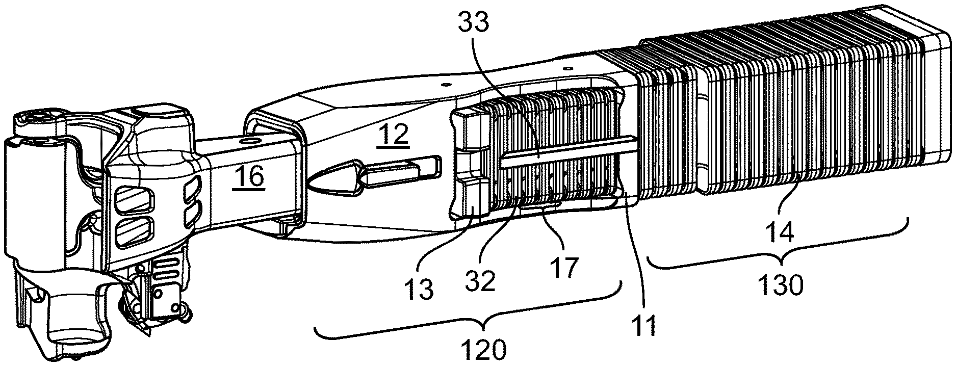
[0007] FIG. 1 depicts an apparatus according to the invention, including a first stack of elastomeric units in the yoke and a second stack of elastomeric units behind the yoke
[0008] FIG. 2 is a cutaway view of an apparatus according to one embodiment of the invention showing the engagement of the yoke with a coupler; and
[0009] FIG. 3 is cutaway view according to another embodiment of the invention.
[0010] The drawings may not be to scale and features not necessary for an understanding of the invention are not shown.
DETAILED DESCRIPTION OF THE INVENTION
[0011] Directions and orientations herein refer to the normal orientation of a railway car in use. Thus, unless the context clearly requires otherwise, the "front" of a coupler is in a direction away from the body of the car and "rear" is in a direction from the front end of the coupler toward the car body. Likewise, the "longitudinal" axis or direction is parallel to the rails and in the direction of movement of the railway car on the track in either direction. The "transverse" or "lateral" axis or direction is in a horizontal plane perpendicular to the longitudinal axis and the rail. The term "inboard" means toward the center of the car, and may mean inboard in a longitudinal direction, a lateral direction, or both. Similarly, "outboard" means away from the center of the car. "Vertical" is the up-and-down direction, "horizontal" is a plane parallel to the surface the train travels on, and "downward" means toward surface the train travels on.
[0012] As used herein, the term "about" associated with a numerical value is understood to indicate a margin of +/-20% of the value. In embodiments, "about" indicates a range of +/-10% of the stated numerical value. In still other embodiments, "about" indicates a range of +/-5% around the stated numerical value. When used to modify a range of values, "about" indicates +/-20%, +/-10% or +/-5% of the range.
[0013] "Droop" is defined as a bending in a downward direction by the coupler shank extending from a railway car. The problem of droop is especially severe in connection with a "floating yoke", where it has been observed that the center of gravity of the yoke is outboard of the end of the railway car.
[0014] "Elastomer" and "elastomeric" refer to polymeric materials having elastic properties so that they exert a restoring force when compressed. Examples of such materials include, without limitation, thermoplastic elastomer (TPE), natural and synthetic rubbers such as: neoprene, isoprene, butadiene, styrene-butadiene rubber (SBR), polyurethanes, and derivatives. Thermoplastic copolyesters used in some conventional draft gear may be used in the stacks of elastomeric units according to the invention.
[0015] "Travel" refers to a distance traveled by the coupler when the cushioning elements are fully compressed. "Travel" generally refers to the full possible extent of such movement, i.e., when the elastomeric pads in a stack of elastomeric units are compressed and the metal plates of adjacent elastomeric units contact one another. Travel may be draft travel, permitted by compression of the first stack of elastomeric units, in the yoke, or may be buff travel, permitted by full compression of the first stack and the second stack of elastomeric units, inside the yoke and behind the yoke. In some cases, clear from the context, in the case of a specific impact event, "travel" may refer to an actual amount of displacement measured.
[0016] A person having ordinary skill in the art has a general knowledge of standards and procedures established by the Association of American Railroads ("AAR") and the published AAR standards cited herein are incorporated by reference as background. Reference herein to AAR standards refers to standards in effect on the filing date of this application. In non-limiting embodiments, the selective cushioning apparatus fits between front and rear stops of an "EOC-7" pocket of about 383/4 inches described in AAR standard S-181. In other embodiments, the cushioning unit fits between front and rear stops of an "EOC-8" pocket, having a pocket length of about 483/4 inches described in AAR standard S-181. In other embodiments, the cushioning device may be adapted to fit other AAR standard or non-standard pocket dimensions depending on the application.
[0017] As used herein the term "E-Type" refers to a yoke connected to a coupler by a coupler key inserted laterally and does not necessarily refer to a standard-dimension yoke. A yoke utilized with a selective cushioning unit according to the invention will typically be shorter than a standard E-Type yoke, to accommodate a stack of elastomeric units behind the yoke, but the configuration would be recognizable as "E-Type" to a person having ordinary skill in the art (from the coupler key) and would be interoperable with railway car components configured for use with a conventional E-Type yoke.
[0018] A cushioning unit according to one embodiment of the invention is depicted in the perspective view of FIG. 1, including a first stack 17 of elastomeric units positioned in front portion 120 forward of vertical wall 11 (not shown in FIG. 1) of the yoke 12, behind the coupler follower 13. In the embodiment shown, a second stack 14 of elastomeric units is positioned in rear portion 130 behind the first stack 17. In this arrangement, first stack 17 absorbs buff and draft loads on coupler 14, whereas second stack 14 absorbs buff loads only. The configuration and operation of these components is substantially the same as described in the aforesaid co-pending applications, incorporated by reference.
[0019] In the cutaway detail view of FIG. 2, The E-Type yoke 12 is adapted to receive a coupler shank 16, the yoke 12 has a front end 18 opposite rear wall 11, a top wall 15 and a bottom wall 19 opposite top wall 15, a first side wall 21 connecting top wall 15 and bottom wall 19, and a second side wall (not shown in the cutaway view) opposite first side wall 21, the first and second side walls each have an aligned key slot toward the front end of the yoke adapted to receive the laterally inserted coupler key 30. The top wall 15 and bottom wall 19 each have an interior surface facing coupler shank 16.
[0020] In the embodiment shown in FIG. 2 a butt support 23 protruding from the interior surface of top wall 15 retains coupler shank 16 when an end of the coupler extending from the railway car is subject to droop. In FIG. 1, the butt support 23 is formed integrally with the wall of the yoke (i.e., as one piece, for example, formed from an indentation in top wall 15). In another embodiment depicted in FIG. 3, holes are provided in top wall 15 to receive fasteners 31, so that butt support 231 can be fastened to interior surface of top wall 15. In this way, butt support 231 may be made removable and adjustable.
[0021] The tail of the yoke, including rear wall 11 is lengthened as compared to a conventional floating yoke in an amount sufficient to place the center of gravity of the yoke inboard of the end of the car to prevent the yoke from drooping as well.
[0022] In embodiments, a first stack of elastomeric units 31 positioned in yoke 12 comprises a set of similarly shaped and sized rigid metal plates 32 configured to be aligned in front of the rear wall of the yoke between the top wall 15 and the bottom wall 19 of the yoke. Each metal plate has at least one elastomeric pad thereon, adapted so that each metal plate contacts an adjacent metal plate at full compression of the first stack. Metal-to-metal contact of the plates after a predetermined amount of compression may serve to prevent over-compression and permanent deformation of the elastomeric pads. In embodiments, the plates may be provided with cooperating features that facilitate alignment of the plates when the stack is fully compressed. Lateral guides 33 may be welded into the sill to assist in alignment of the elastomeric units in the yoke. In embodiments, at full compression, the first stack of elastomeric units allows travel in a range of about 3 to about 3.5 inches, although specific embodiments are not to be deemed as limiting the invention.
[0023] In embodiments, one or more stacks of elastomeric units may be provided behind the yoke to absorb buff loads on the coupler. As in the aforesaid co-pending applications the second ("buff") stack of elastomeric units may comprise a set of rigid metal plates, each metal plate having at least one elastomeric pad thereon, adapted so that each metal plate of the elastomeric units contacts an adjacent metal plate at full compression of the stack. Preferably, full compression of the first stack and the second stack permits buff travel in a range of about 6-18 inches. In embodiments, where the apparatus is adapted to be retrofit into an EOC-7 pocket, at full compression of the first stack and the second stack, the apparatus permits buff travel in a range of about 7 to about 8 inches. In another embodiment, where the apparatus is adapted to be retrofit into an EOC-8 pocket, a longer second stack is provided, which provides buff travel in a range of about 9 to about 10 inches.
[0024] In embodiments, the selective cushioning apparatus is retrofit for a pocket designed for an EOC-7 or EOC-8 end of car arrangement.
[0025] As an additional feature to prevent or eliminate "droop", coupler follower 13 may be provided with a recess to receive coupler 16. In the embodiment shown, coupler follower 13 is provided with a notch to avoid the lateral guide 33.
[0026] The description of the foregoing preferred embodiments is not to be considered as limiting the invention, which is defined according to the appended claims. The person of ordinary skill in the art, relying on the foregoing disclosure, may practice variants of the embodiments described without departing from the scope of the invention claimed. A feature or dependent claim limitation described in connection with one embodiment or independent claim may be adapted for use with another embodiment or independent claim, without departing from the scope of the invention.
* * * * *
D00000
D00001
D00002
D00003
XML
uspto.report is an independent third-party trademark research tool that is not affiliated, endorsed, or sponsored by the United States Patent and Trademark Office (USPTO) or any other governmental organization. The information provided by uspto.report is based on publicly available data at the time of writing and is intended for informational purposes only.
While we strive to provide accurate and up-to-date information, we do not guarantee the accuracy, completeness, reliability, or suitability of the information displayed on this site. The use of this site is at your own risk. Any reliance you place on such information is therefore strictly at your own risk.
All official trademark data, including owner information, should be verified by visiting the official USPTO website at www.uspto.gov. This site is not intended to replace professional legal advice and should not be used as a substitute for consulting with a legal professional who is knowledgeable about trademark law.