Lifting Apparatus
VAN DER VEEN; Adriaan Piet ; et al.
U.S. patent application number 16/959171 was filed with the patent office on 2020-12-24 for lifting apparatus. This patent application is currently assigned to FORTESCUE METALS GROUP LTD. The applicant listed for this patent is FORTESCUE METALS GROUP LTD. Invention is credited to Adriaan Piet VAN DER VEEN, David WALLACE.
| Application Number | 20200398874 16/959171 |
| Document ID | / |
| Family ID | 1000005087708 |
| Filed Date | 2020-12-24 |


| United States Patent Application | 20200398874 |
| Kind Code | A1 |
| VAN DER VEEN; Adriaan Piet ; et al. | December 24, 2020 |
LIFTING APPARATUS
Abstract
An apparatus for attaching a coupler to a railroad car, the apparatus comprising a plurality of actuable coupler locking tabs adapted to engage with a knuckle on said coupler.
| Inventors: | VAN DER VEEN; Adriaan Piet; (East Perth, AU) ; WALLACE; David; (East Perth, AU) | ||||||||||
| Applicant: |
|
||||||||||
|---|---|---|---|---|---|---|---|---|---|---|---|
| Assignee: | FORTESCUE METALS GROUP LTD East Perth, Western Australia AU |
||||||||||
| Family ID: | 1000005087708 | ||||||||||
| Appl. No.: | 16/959171 | ||||||||||
| Filed: | December 21, 2018 | ||||||||||
| PCT Filed: | December 21, 2018 | ||||||||||
| PCT NO: | PCT/AU2018/051390 | ||||||||||
| 371 Date: | June 30, 2020 |
| Current U.S. Class: | 1/1 |
| Current CPC Class: | B61G 3/06 20130101; B61G 9/04 20130101; B61G 1/38 20130101; B61G 7/10 20130101 |
| International Class: | B61G 3/06 20060101 B61G003/06; B61G 7/10 20060101 B61G007/10 |
Foreign Application Data
| Date | Code | Application Number |
|---|---|---|
| Jan 2, 2018 | AU | 2018900006 |
Claims
1. An apparatus for attaching a coupler to a railroad car, the apparatus comprising a plurality of actuable coupler locking tabs adapted to engage with a knuckle on said coupler.
2. The apparatus in accordance with claim 1, wherein the plurality of coupler locking tabs are actuable between engaged and disengaged configurations.
3. The apparatus in accordance with claim 2, wherein the plurality of actuable coupler locking tabs are attached indirectly or directly to a coupler rotator locking shaft, rotatable by a rotary actuator.
4. The apparatus in accordance with claim 1, wherein there are provided at least two coupler locking tabs.
5. The apparatus in accordance with claim 1, wherein there are provided three coupler locking tabs.
6. The apparatus in accordance with claim 1, wherein the or each coupler locking tab comprises an outboard face and an inboard face and the knuckle comprises an outboard face and an inboard face.
7. The apparatus in accordance with claim 6, wherein the inboard face of the or each coupler locking tab is complementary with the inboard face of the coupler.
8. The apparatus in accordance with claim 1, wherein the apparatus comprises a lug, adapted to mate with a corresponding locating recess on the coupler.
9. The apparatus in accordance with claim 1, wherein the apparatus comprises a locating recess, adapted to mate with a corresponding lug on the coupler.
10. The apparatus in accordance with claim 1, wherein the apparatus comprises a lug and a locating recess, adapted to respectively mate with a corresponding locating recess and a corresponding lug on the coupler.
Description
TECHNICAL FIELD
[0001] The present invention relates to an apparatus for lifting and inserting a railroad car coupler.
BACKGROUND ART
[0002] Railroad car couplers are known for joining adjacent railcars including freight cars and passenger cars. Freight car couplers include couplers for articulated connectors and rotary dump style couplers. Couplers generally include a coupler head, a knuckle and a knuckle pivot pin along with an internal mechanism with a lock and a rotary locklift arrangement. The internal mechanism is actuable to move the knuckle between open and closed orientations.
[0003] The equipment that connects the couplings to the rolling stock is known as the draw gear. Draw gear typically comprises a recess into which a shaft of the coupler is inserted and secured.
[0004] Couplers are conventionally inserted into draw gear on railway cars with a drawbar sling. Aligning the coupler shaft with the draw gear recess is difficult as the longitudinal axis of the shaft must be substantially coincident with the recess in the draw gear. To keep the shaft level, it is necessary to locate the centre of gravity of the coupler and attach the sling in the appropriate position.
[0005] In addition, some couplers require rotation of 180.degree. after insertion into the draw gear in order to secure them. Such rotation is not possible with a drawbar song and in any event, requires significant physical effort.
[0006] The preceding discussion of the background to the invention is intended to facilitate an understanding of the present invention. However, it should be appreciated that the discussion is not an acknowledgement or admission that any of the material referred to was part of the common general knowledge in Australia or any other country as at the priority date.
SUMMARY OF INVENTION
[0007] In accordance with the present invention, there is provided an apparatus for attaching a coupler to a railroad car, the apparatus comprising a plurality of actuable coupler locking tabs adapted to engage with a knuckle on said coupler.
[0008] The coupler locking tabs are actuable between engaged and disengaged configurations.
[0009] The apparatus comprises means to actuate the coupler locking tabs between engaged and disengaged configurations. Preferably, the means to actuate the coupler locking tabs between engaged and disengaged configurations is a rotary actuator.
[0010] The plurality of actuable coupler locking tabs are attached indirectly or directly to a coupler rotator locking shaft, rotatable by the rotary actuator.
[0011] Preferably, there are provided at least two coupler locking tabs. In one form of the invention, there are provided three coupler locking tabs. Without being limited by theory, it is believed that where there are three coupler locking tabs, at least two coupler locking tabs will always engage the knuckle when the locking tabs are in the closed configuration.
[0012] In one form of the invention, the or each coupler locking tab comprises an outboard face and an inboard face. In one form of the invention, the knuckle comprises an outboard face and an inboard face.
[0013] Engagement of the inboard face of at least one coupler locking tab with the inboard face of the knuckle on the coupler provides engagement of the lifting apparatus with the coupler. Preferably, the inboard face of the or each coupler locking tab is complementary with the inboard face of the coupler.
[0014] In one form of the invention, the cross-sectional shape of the coupler locking tab is fin shaped.
[0015] Preferably, the rotary actuator is hydraulically operated. The rotary actuator is adapted to lock the coupler locking tabs in the closed configuration.
[0016] In one form of the invention, the apparatus further comprises a lug, adapted to mate with a corresponding locating recess on the coupler.
[0017] In one form of the invention, the apparatus further comprises a locating recess, adapted to mate with a corresponding lug on the coupler.
[0018] In one form of the invention, the apparatus comprises a lug and a locating recess, adapted to respectively mate with a corresponding locating recess and a corresponding lug on the coupler.
[0019] It will be appreciated that the lug may be provided in any shape complimentary to the locating recess on the coupler. It will further be appreciated that the recess on the lifting apparatus may be any shape that is complementary to a lug or protrusion on the coupler.
[0020] Preferably, the apparatus comprises a lifting device releasably engaged with the apparatus.
[0021] The lifting device is preferably engaged with the apparatus with a rotary actuator. The rotary actuator enables the lifting device to not only lift the apparatus, but to rotate the apparatus into the correct location to engage with the coupler. In addition, the lifting apparatus enables the lifting and rotation of the apparatus and the coupler when engaging the coupler with the railroad car. Preferably, the rotary actuator is hydraulically operated.
BRIEF DESCRIPTION OF THE DRAWINGS
[0022] Further features of the present invention are more fully described in the following description of non-limiting embodiments thereof. This description is included solely for the purposes of exemplifying the present invention. It should not be understood as a restriction on the broad summary, disclosure or description of the invention as set out above. The description will be made with reference to the accompanying drawings in which:
[0023] FIG. 1 is a plan view of a coupler and a lifting apparatus in accordance with an embodiment of the invention;
[0024] FIG. 2 is a perspective view of a lifting apparatus in accordance with an embodiment of the invention;
[0025] FIG. 3 is a perspective view of a lifting apparatus in accordance with an embodiment of the invention; and
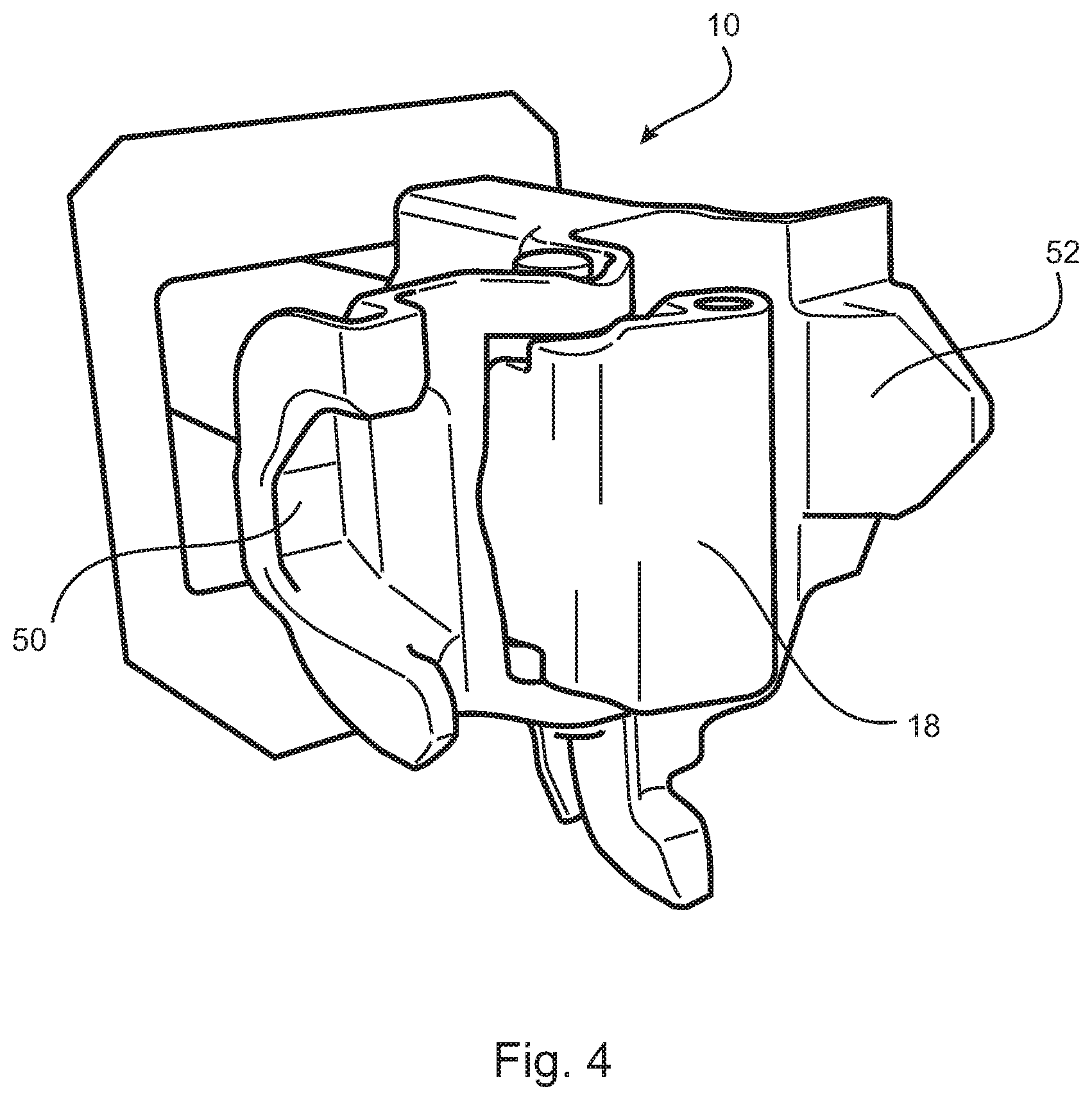
[0026] FIG. 4 is a perspective view of a Type F coupler known in the art.
DESCRIPTION OF EMBODIMENTS
[0027] Throughout this specification, unless the context requires otherwise, the word "comprise" or variations such as "comprises" or "comprising", will be understood to imply the inclusion of a stated integer or group of integers but not the exclusion of any other integer or group of integers.
[0028] Those skilled in the art will appreciate that the invention described herein is amenable to variations and modifications other than those specifically described. It is to be understood that the invention includes all such variations and modifications. The invention also includes all of the steps, features, compositions and compounds referred to or indicated in the specification, individually or collectively and any and all combinations or any two or more steps or features.
[0029] In FIG. 1 there is provided a plan view of a coupler 10 comprising a coupler shaft 12 and a coupler head 14 which may join with a corresponding coupler head of another railcar to couple together two railcars. The coupler shaft 12 extends into rotary yoke (not shown) on the draw gear and through rotary connector (not shown). Coupler shaft 12 is held in place within rotary connector by a connector pin through a cavity 16 in the coupler shaft.
[0030] The coupler head 14 comprises a knuckle 18 pivotally connected to the coupler head by means of a knuckle pivot pin 20. The knuckle pivot pin 20 allows rotational movement of the knuckle 18 for engagement and disengagement of knuckles of connected railroad cars.
[0031] The knuckle 18 has an outboard face 22 and an inboard face 24. In use, two knuckles on opposed couplers engage at their inboard faces.
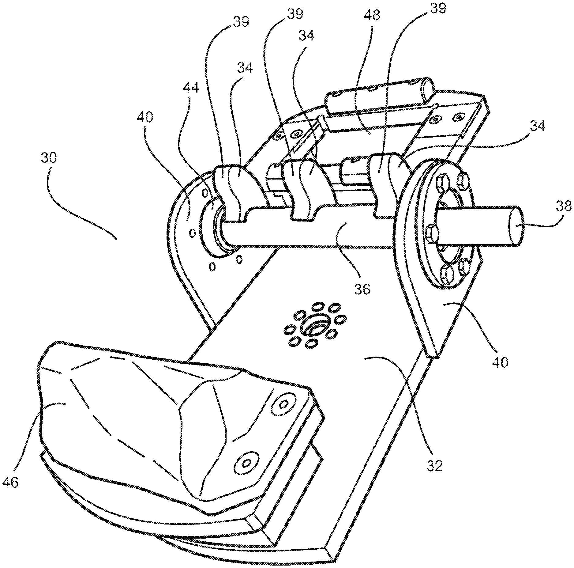
[0032] In FIGS. 2 and 3 there are provided perspective views of a lifting apparatus 30 in accordance with an embodiment of the present invention.
[0033] The lifting apparatus 30 comprises a base 32, three actuable coupler locking tabs 34 attached to a sleeve 36 encasing a coupler rotator locking shaft 38. A rotary actuator (not shown) is adapted to rotate the coupler rotator locking shaft 38 up to 90.degree.. A suitable hydraulic rotary actuator is a helical actuator available from HKS. Rotation of the coupler rotator locking shaft 38 rotates the actuable coupler locking tabs 34 from a disengaged configuration to an engaged configuration. The locking tabs may be locked in the engaged configuration by way of physical/mechanical means that triggers a hydraulic control valve. When in the engaged configuration the locking mechanism cannot be unlocked. A lifting D ring must be in a certain position on the lifting arm to trigger the control valve to enable disengagement.
[0034] The materials used are all 350 grade mild steel plate throughout the apparatus. The locking mechanism rod and bearing housings are 4140 high tensile grade steel, the bearings are aluminum bronze.
[0035] It will be appreciated that the shape of the locking tabs 34 will be influenced at least in part, by the shape of the corresponding knuckle 18 on the coupler 10 and in particular the inboard face 24 thereof. The locking tabs 34 comprise inboard faces 39, adapted to engage the knuckle inboard face 24.
[0036] The coupler rotator locking shaft 38 is mounted between two pillow block mounts 40. There are provided bushes 42, 44 at either end of the coupler rotator locking shaft 38 for engagement with the pillow block mounts 40.
[0037] On the underside of the base 32, there is provided a second rotary actuator (not shown) such as a Helac L20 hydraulic rotary actuator. The rotary actuator is attached to a lifting apparatus (not shown) such as a crane or other mobile device.
[0038] The lifting apparatus 30 further comprises a lug 46 and a locating recess 48. The lug 40 is adapted to engage with a locating recess 50 of a corresponding coupler 10 when in use. The locating recess 42 is adapted to engage with a lug 52 of a corresponding coupler 10 when in use.
[0039] In addition to providing locating assistance, the lug 46 and locating recess 48 facilitate engagement of the lifting apparatus 30 and the coupler 10. It will be appreciated that the shape of the lug 46 and the locating recess 48 will be influenced at least in part, by the features of the coupler to which the lifting apparatus is intended to attach. For example, the lifting apparatus depicted is intended for operation with a Type F rotary coupler known in the art. These further points of engagement are particularly useful when it is necessary to rotate the coupler to secure it to the draw gear.
[0040] In use, the rotary actuator on the underside of the base 32 will attach to a lifting device such as a crane. The lifting device is capable of lifting the apparatus 30 and the rotary actuator serves to retain the apparatus in the correct orientation for attachment to a coupler 10.
[0041] In attaching the lifting apparatus 30 to the coupler 10, the locking tabs 34 must be in the disengaged orientation. It can be inserted into the coupler 10 in the manner shown in FIG. 1. While being held in place, the rotary actuator that operates the locking shaft 38 rotates the locking shaft 38 so that the locking tabs 34 rotate until they engage in the inboard face 24 of the knuckle 18. At the same time, the lug 40 engages with the locating recess 50 of the coupler 10 and the locating recess 42 engages with the lug 52 of the coupler 10.
[0042] The entire coupler 10 may be lifted for insertion into draw gear on a train. The longitudinal axes of the coupler shaft 12 and the corresponding recess in the draw gear may then be accurately aligned. In addition, where the coupler 10 requires 180 rotation after insertion into the draw gear as is the case for Type F rotary couplers, rotation may be performed accurately and controllably. Once engaged, the coupler 10 can be rotated by way of a swash plate manual steering hand pump on the rear base of the apparatus.
[0043] After insertion of the coupler 10 to the draw gear, the rotary actuator that operates the locking shaft 38 rotates the locking shaft 38 so that the locking tabs 34 disengage them from the knuckle 18 and the lifting apparatus 30 may then be removed from the coupler.
[0044] The apparatus of the present invention has been described and depicted with reference to a standard type F coupler. However, it is understood that lifting apparatus having features of the invention may be utilized with other couplers without departing from the scope of the invention.
* * * * *
D00000
D00001
D00002
D00003
D00004
XML
uspto.report is an independent third-party trademark research tool that is not affiliated, endorsed, or sponsored by the United States Patent and Trademark Office (USPTO) or any other governmental organization. The information provided by uspto.report is based on publicly available data at the time of writing and is intended for informational purposes only.
While we strive to provide accurate and up-to-date information, we do not guarantee the accuracy, completeness, reliability, or suitability of the information displayed on this site. The use of this site is at your own risk. Any reliance you place on such information is therefore strictly at your own risk.
All official trademark data, including owner information, should be verified by visiting the official USPTO website at www.uspto.gov. This site is not intended to replace professional legal advice and should not be used as a substitute for consulting with a legal professional who is knowledgeable about trademark law.