Bogie Of A Rail Vehicle
KUETER; CHRISTIAN ; et al.
U.S. patent application number 16/962577 was filed with the patent office on 2020-12-24 for bogie of a rail vehicle. The applicant listed for this patent is SIEMENS MOBILITY AUSTRIA GMBH, SIEMENS MOBILITY GMBH. Invention is credited to CHRISTOPH ADAM, OLAF KOERNER, CHRISTIAN KUETER, ANDREAS SCHAEFER-ENKELER, PETER SEITZ, MARTIN TEICHMANN.
| Application Number | 20200398871 16/962577 |
| Document ID | / |
| Family ID | 1000005075779 |
| Filed Date | 2020-12-24 |

| United States Patent Application | 20200398871 |
| Kind Code | A1 |
| KUETER; CHRISTIAN ; et al. | December 24, 2020 |
BOGIE OF A RAIL VEHICLE
Abstract
A bogie of a rail vehicle has at least one wheelset with two oppositely situated wheels that are rigidly connected to one another, a wheelset bearing arrangement of the wheelset within the two wheels, a traction motor which directly drives the wheelset, and an aerodynamic paneling enclosure of the bogie. The traction motor is a permanently excited synchronous motor with liquid cooling.
| Inventors: | KUETER; CHRISTIAN; (STATTEGG, AT) ; SCHAEFER-ENKELER; ANDREAS; (ROETTENBACH, DE) ; TEICHMANN; MARTIN; (GRAZ, AT) ; ADAM; CHRISTOPH; (NUERNBERG, DE) ; KOERNER; OLAF; (NUERNBERG, DE) ; SEITZ; PETER; (POMMELSBRUNN, DE) | ||||||||||
| Applicant: |
|
||||||||||
|---|---|---|---|---|---|---|---|---|---|---|---|
| Family ID: | 1000005075779 | ||||||||||
| Appl. No.: | 16/962577 | ||||||||||
| Filed: | January 3, 2019 | ||||||||||
| PCT Filed: | January 3, 2019 | ||||||||||
| PCT NO: | PCT/EP2019/050070 | ||||||||||
| 371 Date: | July 16, 2020 |
| Current U.S. Class: | 1/1 |
| Current CPC Class: | B61D 17/02 20130101; B61C 9/50 20130101; H02K 1/32 20130101; B60L 2200/26 20130101; B61F 3/14 20130101 |
| International Class: | B61C 9/50 20060101 B61C009/50; B61F 3/14 20060101 B61F003/14; B61D 17/02 20060101 B61D017/02; H02K 1/32 20060101 H02K001/32 |
Foreign Application Data
| Date | Code | Application Number |
|---|---|---|
| Jan 16, 2018 | EP | 18151837.4 |
Claims
1-6. (canceled)
7. A bogie of a rail vehicle, the bogie comprising: at least one wheelset with two opposing, rigidly interconnected wheels; a wheelset bearing of said at least one wheelset within said two wheels; a traction motor configured to drive said wheelset directly, said traction motor being a permanently excited synchronous motor with liquid cooling; and an aerodynamic enclosure of the bogie.
8. The bogie according to claim 7, wherein said liquid cooling is effected by a liquid cooling jacket.
9. The bogie according to claim 8, wherein said traction motor has a closed internal cooling circuit to be recooled at said liquid cooling jacket and/or at a motor can of a stator of said traction motor.
10. The bogie according to claim 9, wherein said liquid cooling jacket cooling is arranged between a rear side of the stator of said traction motor and the internal cooling circuit.
11. The bogie according to claim 10, wherein said internal cooling circuit includes outer air-guiding ducts.
12. The bogie according to claim 9, further comprising a motor can disposed to separate said stator of said traction motor from a rotor of said traction motor, enabling said stator to be cooled by way of an insulating liquid.
13. A rail vehicle, comprising at least one bogie according to claim 7, and wherein at least one recooling unit of the liquid cooling is arranged in and/or on the rail vehicle.
14. The rail vehicle according to claim 13, configured as a high-speed train.
Description
[0001] The invention relates to a bogie of a rail vehicle with at least one wheelset with two opposing rigidly interconnected wheels, wherein a wheelset bearing of the wheelset is effected within the two wheels and the traction motor is arranged between the wheels of the wheelset.
[0002] Bogies of rail vehicles have traction motors, which are designed as asynchronous machines with self-ventilation or forced ventilation or permanently excited synchronous machines, which drive the wheelsets of the bogie via a transmission. The transmissions are cooled by the head wind which flows through the underfloor region. In the bogie region, self-ventilated traction motors draw in the cooling air and release it back to the surrounding environment. Forced-ventilated traction motors also release their heated cooling air to the surrounding environment in the bogie region. At higher speeds, the head wind then dissipates the heated cooling air of said traction motors in the transmission region.
[0003] In rail vehicles in the higher speed range, however, the aerodynamics, in particular also those of the bogie region, are significant for the energy consumption of the rail vehicles.
[0004] For this reason, as known from WO 2014/206643 A1 and WO 2010/086201 A1, enclosures are provided for the bogie in order to improve the aerodynamics.
[0005] Although this is advantageous for aerodynamic reasons, releasing the heat losses of the traction motors may be difficult or no longer even possible.
[0006] Furthermore, in rail vehicles the wheelset shafts are mounted outside the wheels.
[0007] On this basis, the object underlying the invention is that of providing a bogie with at least one traction motor for rail vehicles, in particular for high-speed trains, which is also able to allow heat dissipation of the at least one traction motor should the bogie have an enclosure.
[0008] The object set is achieved by a bogie of a rail vehicle with: [0009] at least one wheelset with two opposing rigidly interconnected wheels, [0010] a wheelset bearing of the wheelset within the two wheels, [0011] a traction motor, which drives the wheelset directly, wherein the traction motor is a permanently excited synchronous motor with liquid cooling, [0012] an aerodynamic enclosure of the bogie.
[0013] According to the invention, in a bogie with internally mounted wheelset shaft, a full enclosure is now provided which, in particular when viewed from the front, can be designed to be comparatively narrow, as the external bearing of the wheelset has been laid inwardly, i.e. between the wheels of the wheelset, and thus allows more space and parts for an aerodynamic enclosure of the bogie.
[0014] Furthermore, this means that the overall air resistance of the rail vehicle is reduced and contributes towards a significant reduction in the energy consumption of the vehicle. Particularly suitable traction motors are drive motors which operate comparatively efficiently and only require a comparatively low amount of cooling.
[0015] According to the invention, a liquid-cooled permanently excited synchronous motor without transmission in a fully enclosed, internally mounted running gear is therefore suitable for achieving the object set above.
[0016] Permanently excited synchronous machines are comparatively well suited for liquid cooling, as the rotor losses to be dissipated are considerably lower than in asynchronous machines, for example.
[0017] Furthermore, a heat dissipation of the rotor by a liquid cooling inter alia could only be realized in a comparatively technically complex manner due to the rotating seals.
[0018] In order to also exclude the heat source of a transmission, according to the invention a permanently excited synchronous motor is used as a direct drive, so that a cooling of the transmission is dispensed with. Direct drives of this kind may be sensibly realized with permanently excited synchronous motors, but other asynchronous motors are also conceivable.
[0019] In this context, the direct drive is coupled to the wheelset shaft via a coupling. The direct drive is either arranged about the wheelset shaft, in which case the wheelset shaft engages through a hollow shaft of a rotor of the direct drive. Here, the direct drive drives the wheelset by means of a cardan quill shaft coupling.
[0020] Alternatively, the direct drive may also be arranged substantially paraxially next to the wheelset shaft, for example.
[0021] By eliminating the transmission, construction volume within the internally mounted running gear is therefore gained and the additional thermal load due to the transmission is avoided.
[0022] The liquid cooling of the traction motor is arranged in and/or on the stator of said traction motor. In this context, the liquid cooling jacket has cooling coils which run in the circumferential direction or meander paraxially. Furthermore, in addition or as an alternative, cooling tubes may also be arranged in the laminated core of the stator.
[0023] Via a liquid cooling in or on the stator housing, in particular a water-cooling jacket, which is situated on the rear side of the stator and between air-guiding ducts of the internal cooling circuit of the traction motor, it is now possible for the traction motor(s) also to be sufficiently cooled from the running gear region through which ambient air does not flow due to the comparatively thick enclosure of the bogie.
[0024] The quantity of heat absorbed by the water or another cooling liquid from the rotor and/or stator is released to the ambient air via a cooling installation within the rail vehicle and/or via the cooling installation of the current converter.
[0025] A compact and enclosed traction motor is therefore present, wherein in particular a further reduction of the diameter of the stator and axially shorter winding heads are obtained due to the direct drive having a high pole density.
[0026] The invention as well as advantageous embodiments of the invention are explained in greater detail on the basis of schematic representations of exemplary embodiments, in which:
[0027] FIG. 1 shows a schematic traction motor,
[0028] FIG. 2 shows a further traction motor,
[0029] FIG. 3 shows the arrangement of a traction motor on a wheelset shaft,
[0030] FIGS. 4, 5 show schematic representations of enclosures of the bogie and the arrangement of the traction motors.
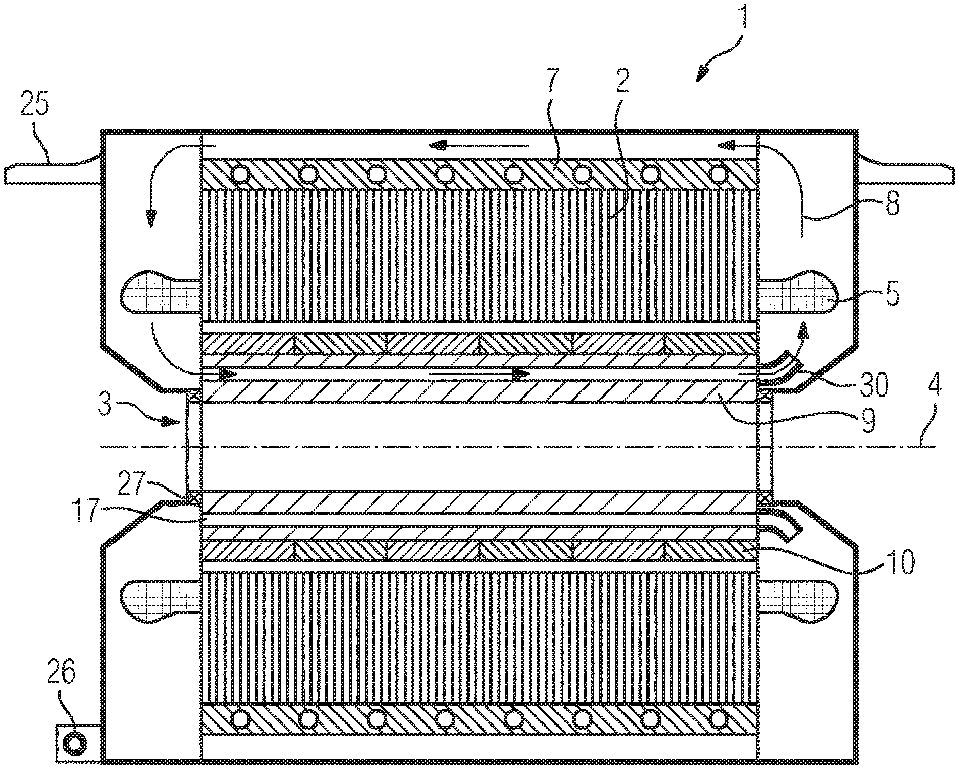
[0031] FIG. 1 shows a schematic representation of a longitudinal section of a permanently excited synchronous motor as traction motor 1 of a rail vehicle (not shown in further detail), in particular high-speed train, with a laminated core layered in the axial direction, which forms the basis of a stator 2. Arranged on the rear side of the stator 2, i.e. the side of the stator 2 facing away from an air gap of the traction motor 1, is a water jacket cooling 7, in order to be able to dissipate the heat loss, which arises during operation of the traction motor 1, from the stator 2. In this case, the cooling tubes of the water jacket cooling 7 substantially run in the circumferential direction.
[0032] Arranged in slots of the stator 2 is a winding system which, by way of electromagnetic interaction with a rotor 3, which is provided with permanent magnets 10, causes a rotation of the rotor 3 about an axis 4. The winding system forms winding heads 5 at the end faces of the stator 2. The permanent magnets 10 of the rotor 3 are arranged as embedded permanent magnets 10 in recesses of the rotor 3 running substantially axially or as surface magnets on the rotor 3, where they are fixed by a bandage for example. The rotor 3 forms a hollow shaft 9, through which the wheelset shaft 16 runs. Furthermore, cooling ducts 17 for an internal cooling circuit 8 are also provided in the rotor 3.
[0033] In this context, the internal cooling circuit 8 is maintained by fans 30, in particular radial fans. The rotor 3 causes comparatively low losses, meaning that a traction motor is also conceivable which has no internal cooling circuit 8, but rather merely dissipates the losses from the traction motor 1 by way of a water jacket cooling 7 at the rear of the stator 2.
[0034] The internal cooling circuit 8, due to the guidance of the air flow, also serves to dissipate heat out from the two end face-side winding heads 5 of the stator 2 and to homogenize the temperature within the traction motor 1.
[0035] The water jacket cooling 7 now causes a cooling of the stator 2, and via the internal cooling circuit 8 a cooling of the rotor 3 and the end face-side winding heads 5. This serves to evenly distribute the temperature within the traction motor 1 and the motor bearings 27.
[0036] The housing of the electric machine 1 is braced against the rotor 3 via motor bearings 27. Furthermore, the housing is positioned via a torque support 26 and a motor brace 25 in the bogie (not shown in further detail).
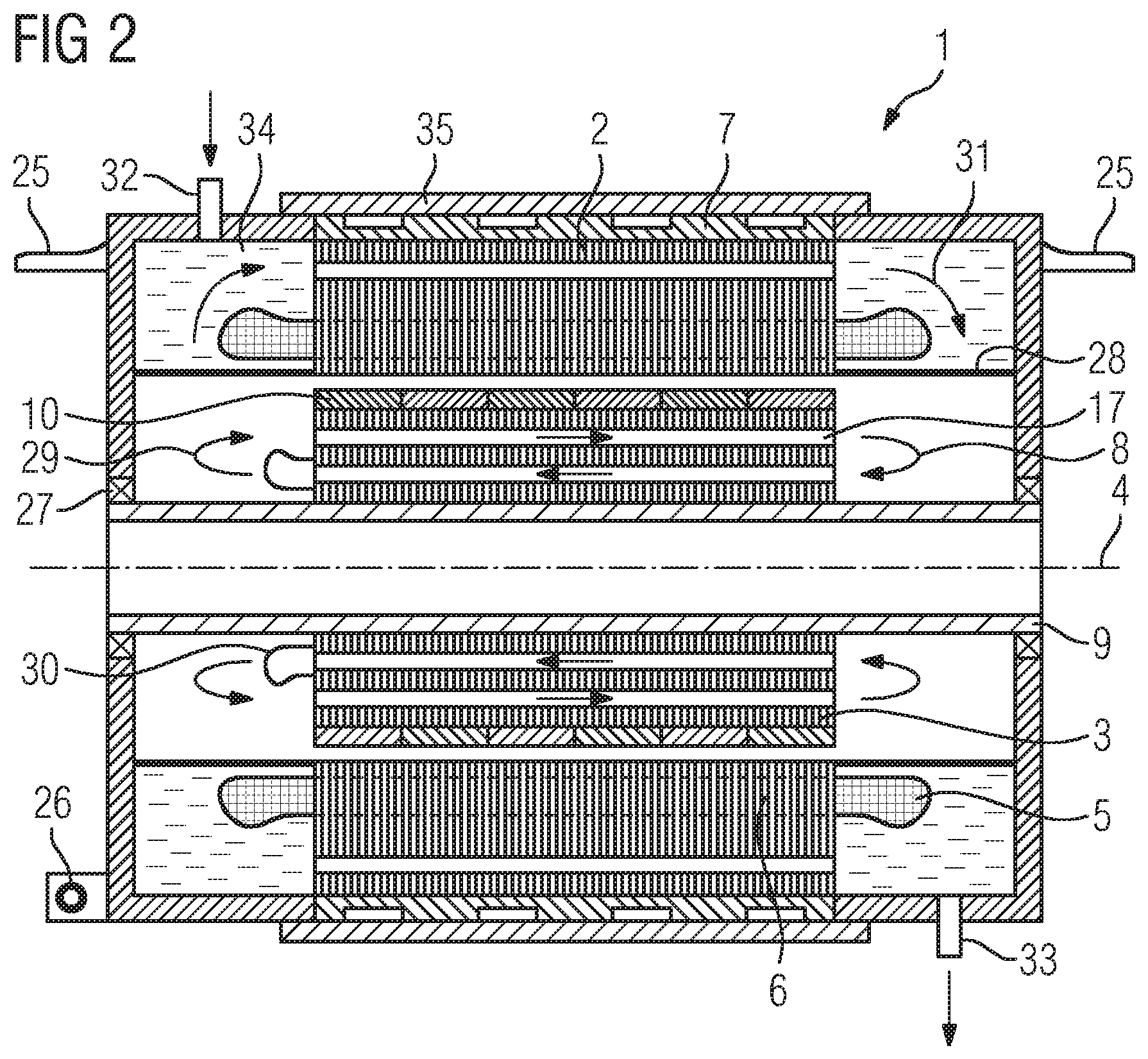
[0037] FIG. 2 shows an alternative embodiment of the electric machine 1, which is likewise designed as a permanently excited synchronous motor, as in FIG. 1. The liquid cooling jacket, which likewise may be designed as a water cooling jacket 7, here is substantially formed from two axially superimposed cylinders, wherein the radially inner cylinder has circumferential recesses which guide the water. The stator 2 is separated from the rotor 3 by a motor can 28, so that the stator 2 can additionally be cooled by an insulating coolant 34, e.g. oil, via an inlet 32 and an outlet 33. In this context, the laminated core of the stator 2 runs through axial cooling ducts.
[0038] An internal cooling circuit 8, the air recirculation of which is maintained by a fan 30, in particular radial fan, is in the rotor 3. A recooling of the internal cooling circuit 8 takes place in contact with the surrounding parts, in particular also on the motor can 28.
[0039] The rotor 3 is designed as a hollow shaft 9 and is connected to a coupling 12 in a rotationally fixed manner, which in turn is connected to the wheelset shaft 3 in a fixed manner, so that the torque of the traction motor 1 can be transferred to the wheelset shaft. A cardan quill shaft coupling is particularly suitable for this purpose.
[0040] In principle, reinforcing elements 14 may be provided within the rotor 3, which intrinsically stabilize the rotor 3. Wheelset bearings 15 within the wheels 11 permit a rotation of the wheelset shaft 16.
[0041] The housing of the electric machine 1 is braced against the rotor 3 via motor bearings 27. Furthermore, the housing is positioned via a torque support 26 and a motor brace 25 in the bogie (not shown in further detail).
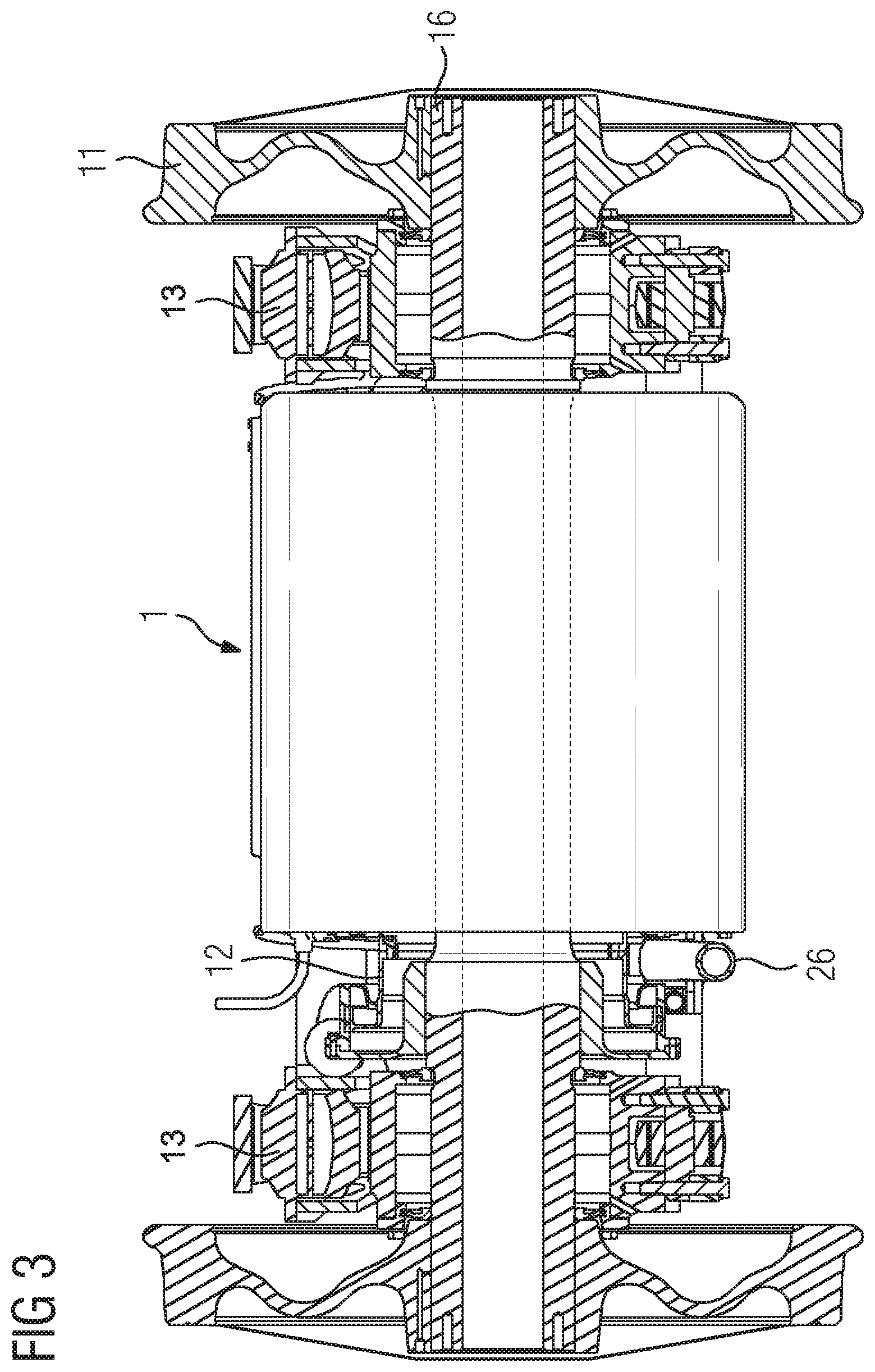
[0042] FIG. 3 shows a wheelset 24 with an electric traction motor 1, which may be designed according to FIG. 1 or FIG. 2. Via a coupling 12, in particular cardan quill shaft coupling, the drive torque of the traction motor 1 is conducted to the wheelset shaft 16. Likewise, the wheelset bearing is arranged between the wheels 11.
[0043] The electric traction motor 1 is therefore fully enclosed and effectively protected from moisture and contamination.
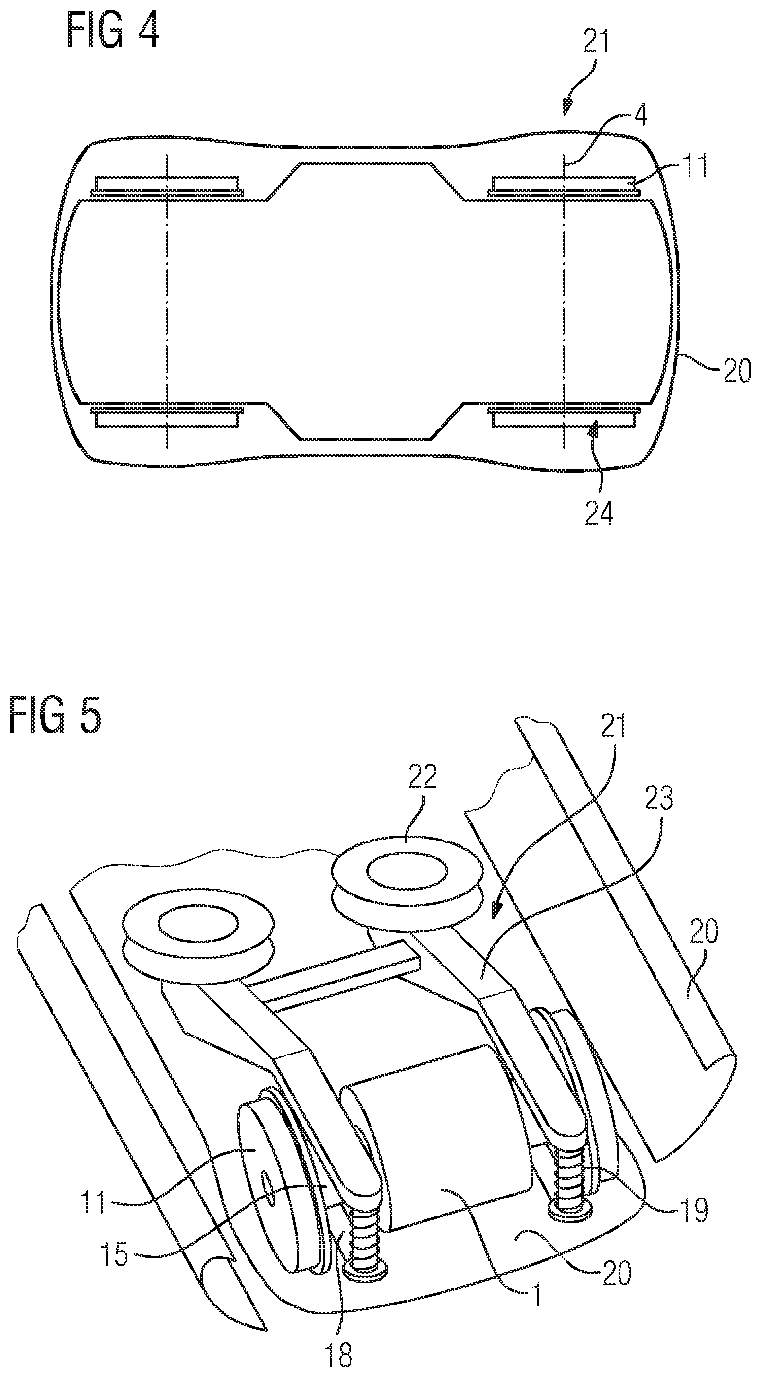
[0044] FIG. 4 shows a schematic representation of a bogie 21, the wheelsets 24 of which with the respective wheels 11, which can be rotated about the axes 4. Furthermore, an enclosure 20 is shown at the underbody, at the side regions and at the front and rear region of the bogie 21. This produces an aerodynamic design of the bogie 21. This may, however, lead to the waste heat problems of a traction motor 1 described above. According to the invention, the cooling system is now configured such that the waste heat, in particular of the traction motor 1, is guided out from the bogie region.
[0045] FIG. 5 shows a schematic perspective representation of a wheelset 24 of a bogie 21, the bogie frame 23 of which is braced via a spring 19 against a support 18, also referred to as wheelset bearing swing arm, and is arranged between the wheels 11 of the traction motor 1. Secondary springs 22 brace the bogie 21 against a vehicle body or rail vehicle body (not shown in further detail).
[0046] Shell-shaped enclosure elements both on the sides and in the direction of travel, as well as on the side of the bogie 21 facing away from the direction of travel, form the enclosure 20. This attempts to keep the gap dimensions between the individual enclosure elements as low as possible, in order to also obtain functional aerodynamics in the turned-out or not turned-out state of the bogie 21. The underside of the bogie 21 is also enclosed, but has recesses (not shown in further detail) for the wheels 11, in order to establish the wheel-rail contact.
[0047] By way of the embodiment of the traction motor 1 according to the invention as a permanently excited synchronous machine with the types of cooling described, in particular water jacket cooling and/or motor can cooling of the stator 2 and/or internal cooling circuit 8, wherein in this context the heat loss is guided outside the region of the bogie 21, a fully functional and aerodynamically designed bogie 21 is now created, which is primarily suitable for high-speed applications.
[0048] The bogie 21 described according to the invention, with one or more permanently excited synchronous motors, which are arranged about the wheelset shaft 15 as a direct drive, have a liquid cooling of the stator 2, have an enclosed internal cooling circuit 8 and have a wheelset bearing axially within the wheels 11, therefore enabling a particularly aerodynamic enclosure of said bogie 21.
[0049] In principle, other motor types may also be used as traction motor 1, for example such as asynchronous motors with squirrel-cage rotors or permanently excited transverse flux machines as direct drives encompassing the wheelset shaft. Likewise, these exemplary motor types may be arranged paraxially and/or connected to the wheelset shaft via a transmission. Likewise, the wheelset shaft 15 may also be arranged axially outside the wheelset shaft 16. The cooling concept accordingly may also have to provide a liquid cooling of the rotor 3. In this case, it is always crucial that the waste heat of the drive is as low as possible and is dissipated out from the fully enclosed bogie region, which is to be designed in an aerodynamic manner.
* * * * *
D00000
D00001
D00002
D00003
D00004
XML
uspto.report is an independent third-party trademark research tool that is not affiliated, endorsed, or sponsored by the United States Patent and Trademark Office (USPTO) or any other governmental organization. The information provided by uspto.report is based on publicly available data at the time of writing and is intended for informational purposes only.
While we strive to provide accurate and up-to-date information, we do not guarantee the accuracy, completeness, reliability, or suitability of the information displayed on this site. The use of this site is at your own risk. Any reliance you place on such information is therefore strictly at your own risk.
All official trademark data, including owner information, should be verified by visiting the official USPTO website at www.uspto.gov. This site is not intended to replace professional legal advice and should not be used as a substitute for consulting with a legal professional who is knowledgeable about trademark law.