Golf Club Head
BAN; Wataru
U.S. patent application number 16/860173 was filed with the patent office on 2020-12-24 for golf club head. This patent application is currently assigned to Bridgestone Sports Co., Ltd.. The applicant listed for this patent is Bridgestone Sports Co., Ltd.. Invention is credited to Wataru BAN.
| Application Number | 20200398121 16/860173 |
| Document ID | / |
| Family ID | 1000004808512 |
| Filed Date | 2020-12-24 |


| United States Patent Application | 20200398121 |
| Kind Code | A1 |
| BAN; Wataru | December 24, 2020 |
GOLF CLUB HEAD
Abstract
An iron type golf club head includes a face member including a face portion and a back surface opposite to the face portion and a main body member which includes a hosel portion and to which the face member is fixed. A plurality of grooves are formed in the back surface. Each of the plurality of grooves includes a first groove portion which is formed on a leading edge side of the face portion in a height direction and extends continuously in a toe-heel direction over an area not less than a half of a width of the back surface in the toe-heel direction.
| Inventors: | BAN; Wataru; (Tokyo, JP) | ||||||||||
| Applicant: |
|
||||||||||
|---|---|---|---|---|---|---|---|---|---|---|---|
| Assignee: | Bridgestone Sports Co.,
Ltd. Tokyo JP |
||||||||||
| Family ID: | 1000004808512 | ||||||||||
| Appl. No.: | 16/860173 | ||||||||||
| Filed: | April 28, 2020 |
| Current U.S. Class: | 1/1 |
| Current CPC Class: | A63B 2053/0479 20130101; A63B 53/047 20130101; A63B 53/0445 20200801; A63B 53/0454 20200801 |
| International Class: | A63B 53/04 20060101 A63B053/04 |
Foreign Application Data
| Date | Code | Application Number |
|---|---|---|
| Jun 24, 2019 | JP | 2019-116605 |
Claims
1. An iron type golf club head that includes a face portion and a hosel portion, comprising: a face member including the face portion and a back surface opposite to the face portion; and a main body member which includes the hosel portion and to which the face member is fixed, wherein a plurality of grooves are formed in the back surface, and each of the plurality of grooves includes a first groove portion which is formed on a leading edge side of the face portion in a height direction and extends continuously in a toe-heel direction over an area not less than a half of a width of the back surface in the toe-heel direction.
2. The golf club head according to claim 1, wherein each of the plurality of grooves includes a second groove portion which extends from a heel-side end portion of the first groove portion to a top line side, and each of the first groove portion and the second groove portion extends along an outline of the face portion.
3. The golf club head according to claim 1, wherein a plurality of ribs are formed in the back surface, and each of the plurality of ribs includes a first rib portion formed on the top line side of the face portion in the height direction.
4. The golf club head according to claim 3, wherein the first rib portion extends continuously in the toe-heel direction over an area not less than the half of the width of the back surface in the toe-heel direction.
5. The golf club head according to claim 4, wherein each of the plurality of ribs includes a second rib portion which extends from a toe-side end portion of the first rib portion to the leading edge side, and each of the first rib portion and the second rib portion extends along the outline of the face portion.
6. The golf club head according to claim 2, wherein the second groove portion extends over an area not less than a half of a heel-side width of the back surface in the height direction.
7. The golf club head according to claim 5, wherein the second rib portion extends over an area not less than a half of a toe-side width of the back surface in the height direction.
8. The golf club head according to claim 3, wherein the plurality of grooves are spaced apart from each other, and the plurality of ribs are spaced apart from each other.
9. The golf club head according to claim 3, wherein the plurality of grooves are two grooves parallel to each other, and the plurality of ribs are two ribs parallel to each other.
10. An iron type golf club head that includes a face portion and a hosel portion, comprising: a face member including the face portion and a back surface opposite to the face portion; and a main body member which includes the hosel portion and to which the face member is fixed, wherein a plurality of ribs are formed in the back surface, and each of the plurality of ribs includes a first rib portion which is formed on a top line side in a height direction of the face portion and extends continuously in a toe-heel direction over an area not less than a half of a width of the back surface in the toe-heel direction.
Description
CROSS-REFERENCE TO RELATED APPLICATION(S)
[0001] This application claims priority to and the benefit of Japanese Patent Application No. 2019-116605 filed on Jun. 24, 2019, the entire disclosure of which is incorporated herein by reference.
BACKGROUND OF THE INVENTION
Field of the Invention
[0002] The present invention relates to an iron type golf club head.
Description of the Related Art
[0003] As a method for improving the performance of the face portion of a golf club head, Japanese Patent Laid-Open No. 2012-071111 discloses a golf club head in which a portion larger in mass than the surroundings is provided at a part that becomes the antinode of the vibration of the face portion. Japanese Patent No. 6095348 discloses a golf club head in which a plurality of grooves are formed in a part of the back surface of the face portion. Japanese Patent Laid-Open No. 10-248970 discloses a golf club head in which the flexural rigidity in the vibration part on the toe side is increased. Japanese Patent No. 5156994 discloses a golf club head in which a reinforcing portion is provided at the position of the node of the vibration at the time of striking a ball. Japanese Patent Laid-Open No. 11-347161 discloses a golf club head whose natural frequency is confined to fall within a specific range.
[0004] In general, an iron type golf club head includes a hosel portion on the heel side and a thick sole portion, so that the toe side of the face portion tends to easily vibrate and the heel side thereof tends to hardly vibrate. Accordingly, the position of the antinode of the natural vibration of the golf club head tends to be located on the top line side and on the toe side with respect to the center of the face portion. If the striking point is in the lower portion of the face portion or in the central portion in the toe-heel direction, the position of the antinode and the striking point are separated, so that a carry of a shot may be decreased.
SUMMARY OF THE INVENTION
[0005] It is an object of the present invention to improve the carry performance upon striking a golf ball at the lower portion of a face portion.
[0006] According to an aspect of the present invention, there is provided an iron type golf club head that includes a face portion and a hosel portion, comprising: a face member including the face portion and a back surface opposite to the face portion; and a main body member which includes the hosel portion and to which the face member is fixed, wherein a plurality of grooves are formed in the back surface, and each of the plurality of grooves includes a first groove portion which is formed on a leading edge side of the face portion in a height direction and extends continuously in a toe-heel direction over an area not less than a half of a width of the back surface in the toe-heel direction.
[0007] Further features of the present invention will become apparent from the following description of exemplary embodiments (with reference to the attached drawings).
BRIEF DESCRIPTION OF THE DRAWINGS
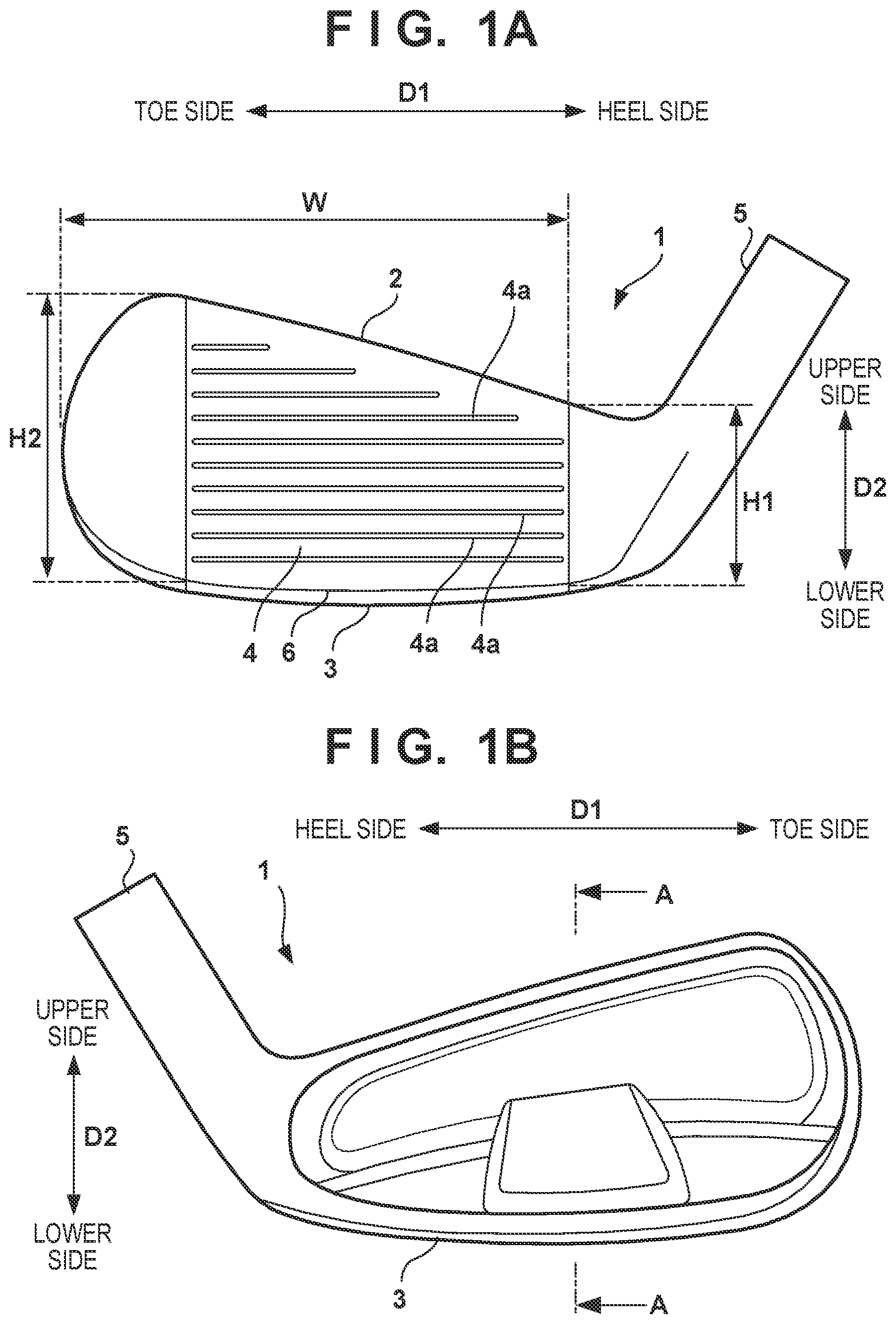
[0008] FIG. 1A is a front view of a golf club head according to an embodiment;
[0009] FIG. 1B is a back view of the golf club head according to the embodiment;
[0010] FIG. 2 is a sectional view taken along a line A-A in FIG. 1B;
[0011] FIG. 3 is a perspective view of a face member on the back surface side;
[0012] FIG. 4 is a view for explaining grooves and ribs;
[0013] FIG. 5 is a view for explaining the position of the antinode of the natural vibration;
[0014] FIG. 6A is a view showing another arrangement example of the grooves;
[0015] FIG. 6B is a view showing still another arrangement example of the ribs; and
[0016] FIG. 6C is a view showing still another arrangement example of the grooves and ribs.
DESCRIPTION OF THE EMBODIMENTS
[0017] Hereinafter, embodiments will be described in detail with reference to the attached drawings. Note that the following embodiments are not intended to limit the scope of the claimed invention, and limitation is not made an invention that requires all combinations of features described in the embodiments. Two or more of the multiple features described in the embodiments may be combined as appropriate. Furthermore, the same reference numerals are given to the same or similar configurations, and redundant description thereof is omitted.
[0018] With reference to FIGS. 1A to 2, a golf club head 1 according to an embodiment of the present invention will be described. FIG. 1A is a front view of the golf club head 1, and FIG. 1B is a back view thereof. FIG. 2 is a sectional view taken along a line A-A in FIG. 1B. In the drawings, an arrow D1 indicates a toe-heel direction, and an arrow D2 indicates a height direction of the face portion. The height direction is a vertical direction parallel to the surface of a face portion 4 in a state in which the golf club head 1 is in contact with the ground in accordance with a predetermined lie angle and a predetermined loft angle.
[0019] The golf club head 1 is an iron type golf club head. The present invention is applicable to any of a long iron, a middle iron, a short iron, and a wedge, but is suitable for a long iron and a middle iron in terms of carry performance.
[0020] The golf club head 1 includes a top line 2 forming the head top portion, a sole portion 3 forming the head bottom portion, the face portion 4, and a hosel portion 5. The hosel portion 5 has a cylindrical shape into which a shaft (not shown) is inserted. The lowermost portion of the face portion 4 forms a leading edge 6.
[0021] The face portion 4 forms a golf ball striking surface. In this embodiment, the face portion 4 forms a flat striking surface, and a plurality of score lines 4a extending in the D1 direction are formed in the D2 direction.
[0022] Referring mainly to FIG. 2, the golf club head 1 is formed by two parts, a face member 10 and a main body member 20. The face member 10 forms a part of the sole portion 3 and the face portion 4, and the main body member 20 forms the remaining part of the golf club head 1 including the hosel portion 5. The periphery portion of the face member 10 is fixed to the main body member 20 by welding or the like. A space 30 is formed between a part of the face member 10 and the main body member 20. The space 30 may be filled with an elastic filler material such as a resin. Note that in this embodiment, the golf club head 1 is formed by two parts, the face member 10 and the main body member 20, but it may be formed by three or more parts.
[0023] With reference to FIGS. 2 to 4, the face member 10 will be further described. The face member 10 of this embodiment includes a wall portion 11 forming the face portion 4 and a wall portion 12 forming the part of the sole portion 3, and is a member having an L-shaped vertical sectional shape as a whole. The wall portion 11 has a plate shape including a front surface 11a and an opposite back surface 11b, and the face portion 4 is formed in the front surface 11a. The back surface 11b has a width Win the D1 direction. As the width (height) in the D2 direction, the back surface 11b has a width H2 on the toe side and a width H1 (H2>H1) on the heel side.
[0024] A plurality of grooves 13 and a plurality of ribs 14 are formed in the back surface 11b. The grooves 13 and the ribs 14 may be formed integrally with the face member 10 by casting, or may be formed by machining such as milling or laser processing. In this embodiments, each of the number of the plurality of grooves 13 and the number of the plurality of ribs 14 is two. However, the number may be three or more, and the numbers of the grooves 13 and the ribs 14 may be different.
[0025] Each groove 13 includes a groove portion 13a and a groove portion 13b, and the grooves 13 are spaced apart from each other and extend in parallel. The grooves 13 may be formed to be non-parallel but not to intersect each other. The groove portion 13a extends continuously along the outline of the face portion 4 in the D1 direction over an area equal to or larger than the half of the width W. The groove portion 13a may extend continuously in the D1 direction over an area of 60% to 90% (both inclusive) of the width W. The groove portion 13b extends along the outline of the face portion 4 in the D2 direction over an area equal to larger than the half of the width H1. The groove portion 13b may extend continuously in the D2 direction over an area of 60% to 90% (both inclusive) of the width H1. In this embodiment, each of the groove portions 13a and 13b is a straight groove, but it may be a curved groove.
[0026] The groove portion 13a is formed on the lower side (leading edge 6 side) with respect to the central portion in the D2 direction. The groove portion 13a may be formed in an area within a range of (1/3).times.the width H2 from the lower side in the direction D2, or may be formed in an area within a range of (1/4).times.H2 or (1/6).times.H2. Assuming that the length of the groove portion 13a in the D1 direction is L11, it is expressed by L11>(1/2).times.W. The length L11 may be expressed by L11.ltoreq.(3/4).times.W or L11.ltoreq.(4/5).times.W. The groove portion 13a may be distributed more on the heel side than on the toe side of the back surface 11b.
[0027] The groove portion 13b is formed on the heel side with respect to the central portion in the D1 direction. The groove portion 13b may be formed in an area within a range of (1/3).times.the width W from the heel side in the D1 direction, or may be formed in an area within a range of (1/4).times.W or (1/6).times.W. Assuming that the length of the groove portion 13b in the D2 direction is L12, it is expressed by L12>(1/2).times.the width H1. The length L12 may be expressed by L12.ltoreq.(3/4).times.H1 or L12.ltoreq.(4/5).times.H1. The groove portion 13b may be distributed more on the lower side than on the upper side of the back surface 11b.
[0028] In this embodiment, the heel-side end portion of the groove portion 13a is connected to the lower end portion of the groove portion 13b, so that the groove 13 has an L-shape as a whole when viewed from the back surface of the wall portion 11. However, the midway portion of the groove portion 13a may be connected to the lower end portion of the groove portion 13b, the heel-side end portion of the groove portion 13a may be connected to the midway portion of the groove portion 13b, or the groove portion 13a may intersect the groove portion 13b. The groove width of the groove 13 falls within, for example, a range of 0.5 mm to 2.0 mm, and the groove depth falls within, for example, a range of 0.1 mm to 1.0 mm. The sectional shape of the groove 13 is rectangular in this embodiment, but may be another shape such as a trapezoid, a semicircle, a semi-ellipse, or a triangle.
[0029] Each rib 14 includes a rib portion 14a and a rib portion 14b, and the ribs 14 are spaced apart from each other and extend in parallel. The ribs 14 may be formed to be non-parallel but not to intersect each other. The rib portion 14a extends continuously along the outline of the face portion 4 in the D1 direction over an area equal to or larger than the half of the width W. The rib portion 14a may extend continuously in the D1 direction over an area of 60% to 90% (both inclusive) of the width W. The rib portion 14b extends along the outline of the face portion 4 in the D2 direction over an area equal to or larger than the half of the width H2. The rib portion 14b may extend continuously in the D2 direction over an area of 60% to 90% (both inclusive) of the width H2. In this embodiment, each of the rib portions 14a and 14b is a straight protrusion, but it may be a curved protrusion.
[0030] The rib portion 14a is formed on the upper side (top line 2 side) with respect to the central portion in the D2 direction. The rib portion 14a may be formed in an area within a range of (1/3).times.the width H2 from the upper side in the direction D2, or may be formed in an area within a range of (1/4).times.H2 or (1/6).times.H2. Assuming that the width of the extending area of the rib portion 14a in the D1 direction is L21, it is expressed by L21>(1/2).times.W. The length L21 may be expressed by L21.ltoreq.(3/4).times.W or L21.ltoreq.(4/5).times.W. The rib portion 14a may be distributed more on the toe side than on the heel side of the back surface 11b.
[0031] The rib portion 14b is formed on the toe side with respect to the central portion in the D1 direction. The rib portion 14b may be formed in an area within a range of (1/3).times.the width W from the toe side in the D1 direction, or may be formed in an area within a range of (1/4).times.W or (1/6).times.W. Assuming that the length of the rib portion 14b in the D2 direction is L22, it is expressed by L22>(1/2).times.the width H2. The length L22 may be expressed by L22.ltoreq.(3/4).times.H2 or L22.ltoreq.(4/5).times.H2. The rib portion 14b may be distributed more on the upper side than on the lower side of the back surface 11b.
[0032] In this embodiment, the toe-side end portion of the rib portion 14a is connected to the upper end portion of the rib portion 14b, so that the rib 14 has a vertically and horizontally inverted L-shape as a whole when viewed from the back surface of the wall portion 11. However, the midway portion of the rib portion 14a may be connected to the upper end portion of the rib portion 14b, the toe-side end portion of the rib portion 14a may be connected to the midway portion of the rib portion 14b, or the rib portion 14a may intersect the rib portion 14b. The rib width of the rib 14 falls within, for example, a range of 0.5 mm to 2.0 mm, and the rib height falls within, for example, a range of 0.1 mm to 1.0 mm. The sectional shape of the rib 14 is rectangular in this embodiment, but may be another shape such as a trapezoid, a semicircle, a semi-ellipse, or a triangle.
[0033] With reference to FIG. 5, the position of the antinode of the natural vibration (primary vibration mode) of the golf club head 1 at the time of striking a ball will be described. In general, an iron type golf club head includes a hosel portion having a rigid structure on the heel side, and the sole width is thicker on the heel side than on the top side. Accordingly, the rigidity is high on the heel side, and low on the toe side and the top line side. Therefore, as shown as a position 15' exemplified in FIG. 5, the position of the antinode of the natural vibration tends to be located at a position on the toe side and the top line 2 side with respect to the central portion of the face portion 4. When a golf ball is struck at the lower portion or the central portion in the D1 direction of the face portion 4, the striking point is deviated from the antinode position 15', so that a carry of a shot may be decreased.
[0034] The iron type golf club head is often used to strike a ball placed on the ground. Accordingly, it has a high frequency of striking a ball at the lower portion of the face portion 4. In this embodiment, since the plurality of grooves 13 and the plurality of ribs 14 are provided, it is possible to make the position of the antinode of the natural vibration closer to the lower portion and central portion of the face portion 4, as shown as a position 15. First, since the groove 13 includes the groove portion 13a, the rigidity of the face member 10 on the sole portion 3 side can be decreased. Accordingly, the antinode position 15' can be moved to the sole portion 3 side. Similarly, since the rib 14 includes the rib portion 14a, the rigidity of the face member 10 on the top line 2 side can be increased. Accordingly, the antinode position 15' can be further moved to the sole portion 3 side. As a result, when a golf ball is struck at the lower portion of the face portion 4, the striking point is closer to the antinode position 15, so that an increase in a carry of a shot can be achieved.
[0035] In addition, since the groove 13 includes the groove portion 13b, the rigidity of the face member 10 on the heel side can be decreased. Accordingly, the antinode position 15' can be moved to the heel side. Similarly, since the rib 14 includes the rib portion 14b, the rigidity of the face member 10 on the toe side can be increased. Accordingly, the antinode position 15' can be further moved to the heel side. As a result, when a golf ball is struck at the central portion of the face portion 4, the striking point is closer to the antinode position 15, so that an increase in a carry of a shot can be achieved.
[0036] In this manner, in this embodiment, the position of the antinode of the natural vibration of the golf club head 1 at the time of striking a ball can be moved closer to the central portion and lower portion of the face portion 4, as shown as the position 15. In this case, when a ball is struck at the lower portion of the face portion 4, which is a frequent striking point, or at the central portion of the face portion 4, which is a striking point upon which a golfer can make a nice shot, the striking point is close to the position 15 of the antinode of the natural vibration, so that a larger carry of a shot can be obtained and the carry performance can be improved.
Other Embodiments
[0037] Both the plurality of grooves 13 and the plurality of ribs 14 are used in the embodiment described above, but it is possible to move the position of the antinode of the natural vibration closer to the central portion of the face portion 4 by using either of the plurality of grooves 13 and the plurality or ribs 14. In addition, the groove 13 may include the groove portion 13a alone, and even in this case, it is possible to move the position of the antinode of the natural vibration closer to the central portion of the face portion 4 in the D2 direction. Similarly, the rib 14 may include the rib portion 14a alone, and even in this case, it is possible to move the position of the antinode of the natural vibration closer to the central portion of the face portion 4 in the D2 direction. FIGS. 6A and 6B show examples of these cases. In the example shown in FIG. 6A, there is no rib 14, and each of the plurality of grooves 13 includes the groove portion 13a alone according to the embodiment described above. In the example shown in FIG. 6B, there is no groove 13, and each of the plurality of ribs 14 includes the rib portion 14a alone according to the embodiment described above.
[0038] In addition, as another example of the plurality of grooves 13, the groove 13 including the groove portion 13b and the groove 13 including no groove portion 13b may be mixed. Similarly, as another example of the plurality of ribs 14, the rib 14 including the rib portion 14b and the rib 14 including no rib portion 14b may be mixed. FIG. 6C shows an example of this case. In the example shown in FIG. 6C, three grooves 13 are formed, and one groove 13 among them includes the groove portions 13a and 13b but each of the remaining two grooves 13 includes the groove portion 13a alone according to the embodiment described above. Further, in the example shown in FIG. 6C, three ribs 14 are formed, and one rib 14 among them includes the rib portions 14a and 14b but each of the remaining two ribs 14 includes the rib portion 14a alone according to the embodiment described above. In the arrangement example shown in FIG. 6C, the position of the antinode of the natural vibration can be moved more in the direction D2 while less in the D1 direction as compared with the example shown in FIG. 4.
[0039] The invention is not limited to the foregoing embodiments, and various variations/changes are possible within the spirit of the invention.
* * * * *
D00000
D00001
D00002
D00003
D00004
D00005
XML
uspto.report is an independent third-party trademark research tool that is not affiliated, endorsed, or sponsored by the United States Patent and Trademark Office (USPTO) or any other governmental organization. The information provided by uspto.report is based on publicly available data at the time of writing and is intended for informational purposes only.
While we strive to provide accurate and up-to-date information, we do not guarantee the accuracy, completeness, reliability, or suitability of the information displayed on this site. The use of this site is at your own risk. Any reliance you place on such information is therefore strictly at your own risk.
All official trademark data, including owner information, should be verified by visiting the official USPTO website at www.uspto.gov. This site is not intended to replace professional legal advice and should not be used as a substitute for consulting with a legal professional who is knowledgeable about trademark law.