Dishwasher
KIM; Ilhwan ; et al.
U.S. patent application number 16/968449 was filed with the patent office on 2020-12-24 for dishwasher. The applicant listed for this patent is LG Electronics Inc.. Invention is credited to Ilhwan KIM, Seunghun KIM, Sangwoo WOO.
| Application Number | 20200397215 16/968449 |
| Document ID | / |
| Family ID | 1000005078626 |
| Filed Date | 2020-12-24 |


| United States Patent Application | 20200397215 |
| Kind Code | A1 |
| KIM; Ilhwan ; et al. | December 24, 2020 |
DISHWASHER
Abstract
A dishwasher is proposed. The dishwasher includes a case accommodating a cleaning target, a sump connected to an interior of the case to collect wash water, a wash pump into which the wash water collected in the sump flows and which generates steam, a steam nozzle spraying the steam, generated in the wash pump, into the case, and a steam valve disposed on a steam path connecting an outlet of the wash pump and the steam nozzle and including an actuator and a valve cap driven by the actuator to open or close the steam path.
| Inventors: | KIM; Ilhwan; (Seoul, KR) ; KIM; Seunghun; (Seoul, KR) ; WOO; Sangwoo; (Seoul, KR) | ||||||||||
| Applicant: |
|
||||||||||
|---|---|---|---|---|---|---|---|---|---|---|---|
| Family ID: | 1000005078626 | ||||||||||
| Appl. No.: | 16/968449 | ||||||||||
| Filed: | February 8, 2019 | ||||||||||
| PCT Filed: | February 8, 2019 | ||||||||||
| PCT NO: | PCT/KR2019/001568 | ||||||||||
| 371 Date: | August 7, 2020 |
| Current U.S. Class: | 1/1 |
| Current CPC Class: | A47L 15/4278 20130101; A47L 15/4234 20130101; A47L 15/4214 20130101 |
| International Class: | A47L 15/42 20060101 A47L015/42 |
Foreign Application Data
| Date | Code | Application Number |
|---|---|---|
| Feb 8, 2018 | KR | 10-2018-0015778 |
Claims
1. A dishwasher, comprising: a case accommodating a cleaning target; a sump connected to an interior of the case to store wash water; a wash pump into which the wash water stored in the sump flows, and generating steam; a steam nozzle spraying the steam, generated in the wash pump, into the case; and a steam valve configured such that a valve cap is driven by an actuator, and opening or closing a steam path which connects the wash pump and the steam nozzle.
2. The dishwasher of claim 1, wherein the valve cap is stretched and shrunk in the steam path by the actuator to open or close the steam path, and seals the actuator.
3. The dishwasher of claim 2, wherein the steam valve comprises a valve chamber, a valve-chamber inlet communicating with the wash pump to introduce steam and a valve-chamber outlet communicating with the steam nozzle to discharge the steam being formed in the valve chamber, and the valve cap is accommodated in the valve chamber to open or close the valve-chamber inlet.
4. The dishwasher of claim 3, wherein the valve cap is disposed to be opposite to the valve-chamber inlet, and is linearly stretched and shrunk by the actuator to open or close the valve-chamber inlet.
5. The dishwasher of claim 4, wherein the valve chamber is opened at a side surface opposite to the valve-chamber inlet, so that the valve cap is inserted into and coupled to the valve chamber, and the valve cap comprises at least one gasket on a coupling part coupled to the valve chamber.
6. The dishwasher of claim 5, wherein the valve cap is made of an elastic material, with at least one gasket being formed on the coupling part coupled to the valve chamber.
7. The dishwasher of claim 4, wherein the valve chamber comprises a protrusion which extends from a surface having the valve-chamber inlet to an inside of the valve chamber by a predetermined length, with the valve-chamber inlet being formed on the protrusion.
8. The dishwasher of claim 2, wherein the steam valve comprises a roof member comprising a coupling part which has a hole at a side thereof to be coupled to a head of the actuator, and a roof which surrounds an upper portion of the actuator, and the valve cap is coupled to the coupling part of the roof member coupled to the head of the actuator.
9. The dishwasher of claim 8, wherein the valve cap is provided to be integrated with the roof member.
10. The dishwasher of claim 1, wherein the steam valve is disposed on a base in the case on which the sump and the wash pump are disposed.
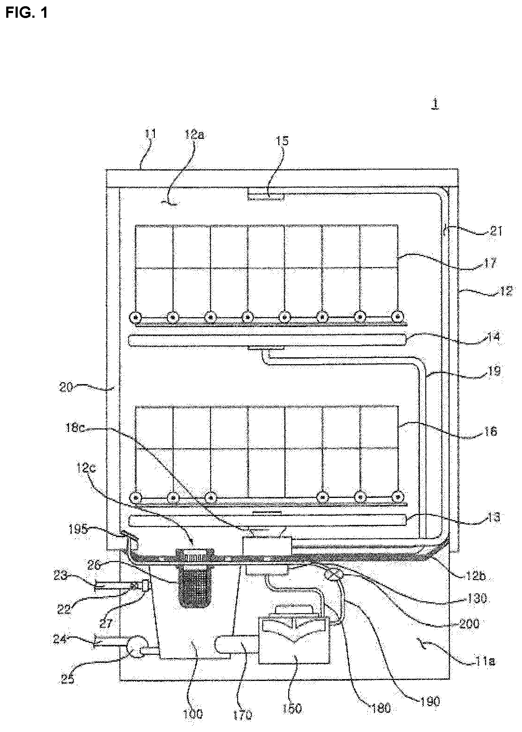
11. The dishwasher of claim 10, wherein the steam valve is disposed on the base such that a path length between the steam valve and the steam nozzle is longer than a path length between the steam valve and the wash pump.
Description
TECHNICAL FIELD
[0001] The present disclosure relates to a dishwasher including a steam valve.
BACKGROUND ART
[0002] A dishwasher is a home appliance that washes dishes or cooking utensils, etc. (hereinafter referred to as a `cleaning target`) to remove waste such as food residues therefrom by high-pressure wash water sprayed from a spray arm.
[0003] The dishwasher washes the cleaning target using heated wash water or performs a washing operation or a sterilizing operation by supplying steam to the cleaning target. A structure where a heater is installed in a wash pump to efficiently generate steam has been proposed. In addition, a structure where a steam nozzle for spraying steam is disposed on a lower end of a door so that steam is efficiently applied to the cleaning target has been proposed.
[0004] Such a dishwasher requires a steam valve which closes a steam path so that wash water does not flow into the steam nozzle when wash water is sprayed through a spray arm, and opens the steam path so that steam flows into the steam nozzle when steam is sprayed through the steam nozzle.
[0005] As the related art, there has been proposed a dishwasher using a valve which is manually closed by pressure of the wash water using a mechanical valve. However, this is problematic in that the valve is not completely opened or closed when the pressure of the wash water is not sufficient, so that some wash water may flow into the steam path, thereby causing a pressure loss of the wash water conveyed by the spray arm.
DISCLOSURE
Technical Problem
[0006] The present disclosure is to control a dishwasher using steam so that wash water does not flow into a steam path when the wash water is sprayed.
[0007] Furthermore, the present disclosure is to protect a steam valve so that the steam valve is not damaged by steam, wash water or other foreign materials in a dishwasher.
[0008] Technical objects to be achieved by the present disclosure are not limited to the aforementioned technical objects, and other technical objects not described above may be evidently understood by a person having ordinary skill in the art to which the present disclosure pertains from the following description.
Technical Solution
[0009] A dishwasher according to an embodiment of the present disclosure may include a case accommodating a cleaning target; a sump connected to an interior of the case to store wash water; a wash pump into which the wash water stored in the sump flows, and which generates steam; a steam nozzle spraying the steam, generated in the wash pump, into the case; and a steam valve configured such that a valve cap is driven by an actuator, and opening or closing a steam path which connects the wash pump and the steam nozzle.
[0010] The valve cap may be stretched and shrunk in the steam path by the actuator to open or close the steam path, and seal the actuator.
[0011] The steam valve may include a valve chamber, a valve-chamber inlet communicating with the wash pump to introduce steam and a valve-chamber outlet communicating with the steam nozzle to discharge the steam being formed in the valve chamber.
[0012] The valve cap may be accommodated in the valve chamber to open or close the valve-chamber inlet.
[0013] The valve cap may be disposed to be opposite to the valve-chamber inlet, and be linearly stretched and shrunk by the actuator to open or close the valve-chamber inlet.
[0014] The valve chamber may be opened at a side surface opposite to the valve-chamber inlet, so that the valve cap may be inserted into and coupled to the valve chamber.
[0015] The valve cap may include at least one gasket on a coupling part coupled to the valve chamber.
[0016] The valve cap may be made of an elastic material, with at least one gasket being formed on the coupling part coupled to the valve chamber.
[0017] The valve chamber may include a protrusion which extends from a surface having the valve-chamber inlet to an inside of the valve chamber by a predetermined length, with the valve-chamber inlet being formed on the protrusion.
[0018] The steam valve may include a roof member including a coupling part which has a hole at a side thereof to be coupled to a head of the actuator, and a roof which surrounds an upper portion of the actuator.
[0019] The valve cap may be coupled to the coupling part of the roof member coupled to the head of the actuator.
[0020] The valve cap may be provided to be integrated with the roof member.
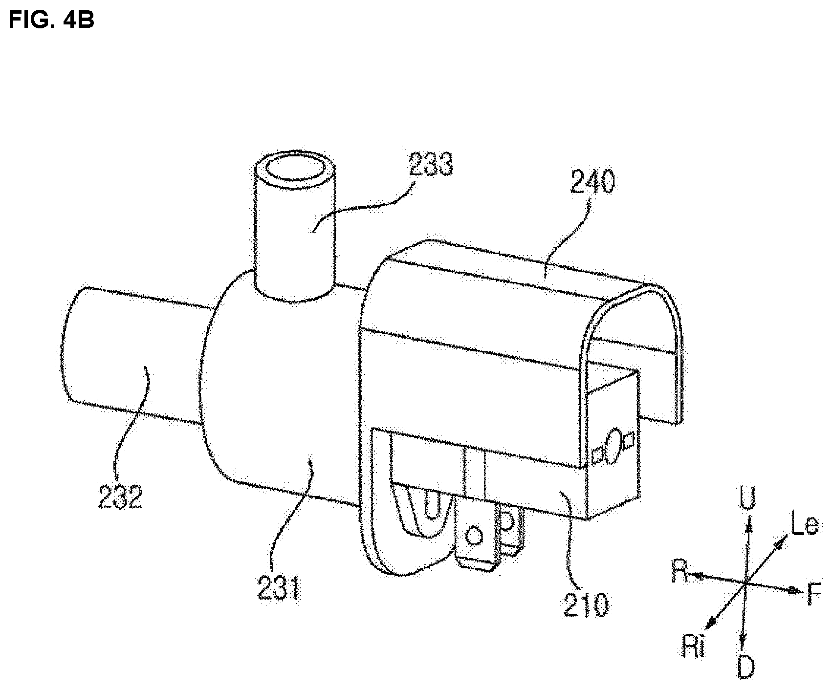
[0021] The steam valve may be disposed on a base in the case on which the sump and the wash pump are disposed.
[0022] The steam valve may be disposed on the base such that a path length between the steam valve and the steam nozzle is longer than a path length between the steam valve and the wash pump.
[0023] Specific details of other embodiments are included in the detailed description and drawings.
Advantageous Effects
[0024] A dishwasher according to the present disclosure has one or more effects as follows.
[0025] First, it is advantageous in that a steam path is electrically opened or closed using a steam valve including an actuator and a valve cap, thus preventing wash water from flowing into a steam path when steam is not sprayed, and thereby reducing a pressure loss when the wash water is sprayed.
[0026] Second, it is advantageous in that a valve cap is moved by an actuator, and a structure for effectively opening or closing a steam inlet is provided, thus effectively closing a steam path.
[0027] Third, it is advantageous in that an actuator that is an electronic device vulnerable to moisture is configured to be protected from steam, wash water, and other foreign materials, thus preventing a steam valve from malfunctioning and being damaged.
[0028] Effects which may be obtained by the present disclosure are not limited to the aforementioned effects, and other technical effects not described above may be evidently understood by a person having ordinary skill in the art to which the present disclosure pertains from the following description.
DESCRIPTION OF DRAWINGS
[0029] FIG. 1 is a diagram illustrating a schematic structure of a dishwasher in accordance with an embodiment of the present disclosure.
[0030] FIG. 2 is a diagram illustrating a configuration of the dishwasher in accordance with the embodiment of the present disclosure.
[0031] FIG. 3 is a diagram illustrating the placement of a steam valve in the dishwasher in accordance with the embodiment of the present disclosure.
[0032] FIG. 4A is a perspective view of the steam valve of the dishwasher in accordance with the embodiment of the present disclosure when seen from one side, and FIG. 4B is a perspective view of the steam valve when seen from the other side.
[0033] FIG. 5 is an exploded perspective view of the steam valve of the dishwasher in accordance with the embodiment of the present disclosure.
[0034] FIGS. 6A and 6B are diagrams illustrating an operation of the steam valve of the dishwasher in accordance with the embodiment of the present disclosure.
[0035] FIG. 7 is a perspective view of a roof member in the dishwasher in accordance with the embodiment of the present disclosure.
[0036] FIG. 8 is a sectional view of the roof member of FIG. 7.
MODE FOR INVENTION
[0037] The above and other objects, features and other advantages of the present disclosure will be more clearly understood from the following detailed description when taken in conjunction with the accompanying drawings. However, it is to be understood that the present disclosure may be embodied in many different forms without being limited to embodiments which will be described later. These embodiments are intended to make the disclosure of the invention complete, and are provided to be fully understood by a person having ordinary skill in the art to which the present disclosure pertains. The present disclosure is merely defined by the scope of claims. The same reference numerals are used throughout the drawings to designate the same components.
[0038] Hereinafter, a dishwasher according to embodiments of the present disclosure will be described with reference to the accompanying drawings.
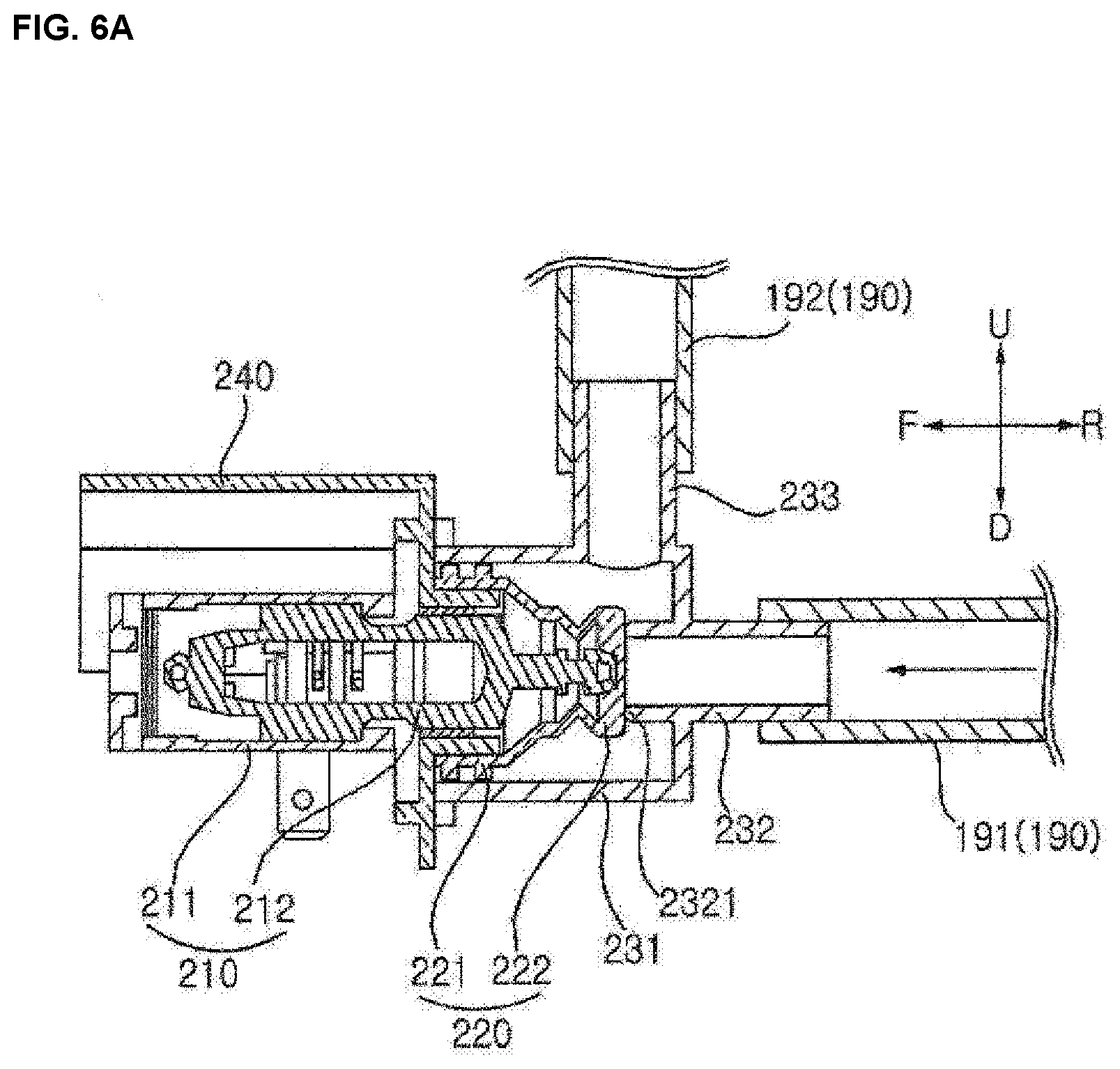
[0039] FIG. 1 is a diagram illustrating a schematic structure of a dishwasher in accordance with an embodiment of the present disclosure.
[0040] FIG. 2 is a diagram illustrating a configuration of the dishwasher in accordance with the embodiment of the present disclosure.
[0041] FIG. 3 is a diagram illustrating the placement of a steam valve in the dishwasher in accordance with the embodiment of the present disclosure.
[0042] The dishwasher 1 in accordance with the embodiment of the present disclosure a case 11 which defines an appearance thereof, a tub 12 which is provided in the case 11 and defines a wash chamber 12a accommodating a cleaning target therein, a door 20 which is provided on a front of the tub 12 to open or close the wash chamber 12a, a sump 100 which is disposed under the tub 12 to store wash water, a plurality of spray arms 13, 14, and 15 which sprays wash water into the tub 12, a wash pump 150 which supplies the wash water stored in the sump 100 to the plurality of spray arms 13, 14, and 15 to generate steam, a steam nozzle 195 which is provided on a door 20 to spray the steam generated in the wash pump 150 to the wash chamber 12a, a steam hose 190 which connects the wash pump 150 and the steam nozzle 195, and a steam valve 200 which is disposed on a base 11 a of the case 11 to open or close a steam path in the steam hose 190.
[0043] The case 11 may be composed of a case upper part and a case lower part, so that the case 11 may be formed by combining the case upper part and the case lower part. The case 11 may include the base 11a that is a lower part of a tub bottom 12b, with the wash pump 150, the sump 100, and the like being disposed in the base. The base 11a may be a space in which various components of the dishwasher 1 are disposed and which is distinguished from a space in which the cleaning target is washed.
[0044] The tub 12 is formed in the shape of a hexahedron which is opened at the front, and defines a wash chamber 12a therein. A communication hole 12c is formed in the bottom 12b of the tub 12 so that wash water flows into the sump 100. The wash chamber 12a is provided with a plurality of racks 16 and 17 to receive the cleaning target. The plurality of racks 16 and 17 includes a lower rack 16 disposed in a lower portion of the wash chamber 12a, and an upper rack 17 disposed in an upper portion of the wash chamber. The lower rack 16 and the upper rack 17 may be vertically disposed to be spaced apart from each other, and may be taken out from the tub 12 by sliding forwards.
[0045] The plurality of spray arms 13, 14, and 15 is vertically disposed. The plurality of spray arms 13, 14, and 15 includes a lower spray arm 13 which is disposed on a lowermost portion to spray wash water towards the lower rack 16 from bottom to top, an upper spray arm 14 which is disposed above the lower spray arm 13 to spray wash water towards the upper rack 17 from bottom to top, and a top spray arm 15 which is disposed on an upper end of the wash chamber 12a that is above the upper spray arm 14 to spray wash water from top to bottom.
[0046] The plurality of spray arms 13, 14, and 15 is supplied with wash water through a plurality of spray-arm connecting paths 18, 19, and 21 from the wash pump 150. The plurality of spray-arm connecting paths 18, 19, and 21 includes a lower spray-arm connecting path 18 connected to the lower spray arm 13, an upper spray-arm connecting path 19 connected to the upper spray arm 14, and a top spray-arm connecting path 21 connected to the top spray arm 15.
[0047] The sump 100 is disposed under the bottom 12b of the tub 12 to collect the wash water. The sump 100 is connected to a water supply path 23 through which the wash water supplied from an external water source flows. A water supply valve 22 is provided on the water supply path 23 to regulate the wash water supplied from the external water source. If the water supply valve 22 is opened, the wash water supplied from the external water source flows through the water supply path 23 into the sump 100. A flowmeter 27 is provided on the water supply path 23 to measure the flow rate of the wash water flowing through the water supply path 23 to the sump 100.
[0048] The sump 100 is connected to a drain path 24 which guides the stored wash water to an outside of the dishwasher 1. A drain pump 25 is provided on the drain path 24 to drain the wash water in the sump 100 through the drain path 24. If the drain pump 25 is driven, the wash water stored in the sump 100 flows through the drain path 24 to the outside of the case 11.
[0049] The sump 100 may be disposed on the base 11a of the case 11.
[0050] A filter 26 is mounted in the communication hole 12c to filter waste from the wash water which flows from the tub 12 to the sump 100.
[0051] The wash pump 150 supplies the wash water stored in the sump 100 to at least one of the plurality of spray arms 13, 14, and 15. The wash pump 150 is connected to the switch valve 130 via a wash-water supply path 180. If the wash pump 150 is driven, the wash water stored in the sump 100 flows through a water collecting path 170 into the wash pump 150, and then is pumped through the wash-water supply path 180 to the switch valve 130. The wash pump 150 may heat the wash water transferred to the wash-water supply path 180.
[0052] The wash pump 150 heats the wash water stored therein to generate steam. The wash pump 150 is connected to the steam hose 190. The steam generated in the wash pump 150 is supplied through the steam hose 190 to the steam nozzle 195.
[0053] Steam hoses 191 and 192 may include a first steam hose 191 which connects the wash pump 150 and the steam valve 200, and a second steam hose 192 which connects the steam valve 200 and the steam nozzle 195.
[0054] The steam valve 200 may be disposed on the steam path connecting an outlet of the wash pump 150 and the steam nozzle 195 to open or close the steam path.
[0055] One end of the steam valve 200 may be connected to the outlet of the wash pump 150, while the other end may be connected to the steam nozzle 195. The outlet of the wash pump 150 may be a path through which the wash water pressurized by the wash pump 150 is discharged.
[0056] The steam valve 200 may include an actuator 210, and a valve cap 220 which is driven by the actuator to open or close the steam path. The steam valve 200 may further include a valve chamber 230 which accommodates the valve cap 220 and through which the steam is introduced and discharged, and a roof member 240 which surrounds the upper portion of the actuator 210.
[0057] The steam valve 200 is configured such that the valve cap 220 is driven by the actuator 210 to open or close the steam path connecting the wash pump 150 and the steam nozzle 195.
[0058] The steam valve 200 may be disposed on the steam hoses 191 and 192 to be closer to the wash pump 150 than the steam nozzle 195, thus blocking wash water introduced through the front ends of the steam hoses 191 and 192.
[0059] Referring to FIG. 1, the steam valve 200 may be disposed on the base 11a that is located under the bottom 12b of the tub 12 in the case 11. Thereby, it is possible to control the flow of the steam or wash water flowing through the steam hoses 191 and 192 without interfering with a space of the wash chamber 12a.
[0060] Meanwhile, the steam valve 200 may be disposed such that a path length between the steam valve 200 and the steam nozzle 195 is longer than a path length between the steam valve 200 and the wash pump 150. As the steam valve 200 becomes closer to the wash pump 150 on the steam path, the inflow of the wash water into the steam path may be blocked. Thereby, when the wash water is sprayed, an amount of the wash water which is discharged from the wash pump 150 and is introduced into the steam path is reduced, so that the pressure loss of the wash water may be reduced. The steam valve 200 will be described below in detail with reference to FIG. 4 and the like.
[0061] The wash pump 150 is installed on a side of the sump 100. The wash pump 150 may be disposed on the base 11a of the case 11.
[0062] The heater 140 is coupled to a lower side of the wash pump 150 to heat the wash water in the wash pump 150. The heater 140 heats the wash water flowing in the wash pump 150 when the wash pump 150 is operated, thus generating hot water. The heater 140 heats the wash water stored in the wash pump 150 when the wash pump 150 is stopped, thus generating steam.
[0063] The hot water generated by the heater 140 is sprayed into the tub 12 through at least one of the plurality of spray arms 13, 14, and 15. The steam generated by the heater 140 flows along the steam hose 190 and then is discharged through the steam nozzle 195 into the tub 12.
[0064] The steam nozzle 195 is provided on the lower end of the door 20 to spray the steam to the wash chamber 12a. The steam sprayed from the steam nozzle 195 acts on the cleaning target received in the lower rack 16 and/or the upper rack 17.
[0065] The switch valve 130 selectively connects the sump 100 to at least one of the plurality of spray arms 13, 14, and 15. The switch valve 130 selectively supplies the wash water pumped by the wash pump 150 to at least one of the lower spray arm 13, the upper spray arm 14, and the top spray arm 15. The switch valve 130 selectively connects the wash-water supply path 180 to at least one of the plurality of spray-arm connecting paths 18, 19, and 21. The switch valve 130 is disposed on the sump 100.
[0066] A check valve 175 is disposed between the sump 100 and the wash pump 150 to be opened in a direction from the sump 100 to the wash pump 150. The check valve 175 is opened so that the wash water flows from the sump 100 to the wash pump 150, and is closed so that the steam does not flow from the wash pump 150 to the sump 100. A lower portion of the check valve 175 rotates about an upper portion, so that the check valve is opened. The check valve 175 is disposed in the water collecting path 170 or connects the water collecting path 170 and the wash pump 150 to open or close the water collecting path 170.
[0067] The check valve 175 is closed when the heater 140 generates the steam. The check valve 175 is opened when the wash pump 150 is operated, so that the wash water flows, and is closed when the wash pump 150 is stopped, so that the wash water does not flow. The check valve 175 is opened by the flow pressure of the wash water of the wash pump 150. According to an embodiment, the check valve 175 may be a solenoid valve that is opened or closed by an electronic signal.
[0068] The check valve 175 is formed so that the wash water flows from the wash pump 150 to the sump 100, even when the check valve is closed during the operation of the drain pump 25.
[0069] FIG. 4A is a perspective view of the steam valve of the dishwasher in accordance with the embodiment of the present disclosure when seen from one side, and FIG. 4B is a perspective view of the steam valve when seen from the other side.
[0070] FIG. 5 is an exploded perspective view of the steam valve of the dishwasher in accordance with the embodiment of the present disclosure.
[0071] FIGS. 6A and 6B are diagrams illustrating an operation of the steam valve of the dishwasher in accordance with the embodiment of the present disclosure.
[0072] Referring to FIGS. 4A and 4B, the steam valve 200 may include an actuator 210 which provides a driving force, a valve cap 220 which is driven by the actuator 210, a valve chamber 230 which accommodates the valve cap 220 and temporarily accommodates steam, and a roof member 240 which protects the actuator 210 from water or external foreign materials.
[0073] Referring to FIGS. 5, 6A, and 6B, the actuator 210 may include an actuator head 212 including a driving end which moves both in one direction and in the other direction, and an actuator body 211 which generates a driving force to move the driving end.
[0074] For example, the actuator 210 may linearly move the driving end forwards and backwards or upwards and downwards or leftwards and rightwards.
[0075] The actuator 210 may be composed of a solenoid valve.
[0076] Alternatively, the actuator 210 may be composed of a thermal actuator. When the actuator is the thermal actuator, it is possible to drive the valve cap 220 at high pressure even with a relatively small volume as compared with the solenoid valve.
[0077] The actuator head 212 may include a cylindrical head part, and a driving end which further protrudes from the head part to an outside of the actuator 210, and is moved in a direction where it is away from a center of the actuator 210 or in a direction where it is closer to the center of the actuator 210.
[0078] The actuator head 212 may be coupled to the valve cap 220 and the roof member 240 which will be described later.
[0079] The valve cap 220 may be coupled to the actuator head 212 to receive the driving force from the actuator 210.
[0080] One end of the valve cap 220 may be coupled to the actuator head 212, and the other end may be stretched and shrunk by the actuator 210 to open or close the steam path. Furthermore, the valve cap 220 may seal the actuator 210 from fluid (steam or water) flowing in the steam hose.
[0081] The valve cap 220 may be stretched and shrunk in the steam path by the actuator 210 to open or close the steam path. Furthermore, the valve cap 220 may seal the actuator 210, thus preventing fluid (steam or water) flowing in the steam hose from flowing into the actuator 210.
[0082] The valve cap 220 may include a coupling part 221 that is coupled to the actuator 210, and a deforming part 222 that is deformed by a driving force transmitted from the actuator 210.
[0083] The valve cap 220 may generally have a cylindrical shape, and be shaped such that the diameter of the cylinder changes. The valve cap 220 may be shaped such that the diameter of the coupling part 221 is larger than the diameter of the deforming part 222.
[0084] The valve cap 220 may be made of an elastic material such as rubber, and then be coupled to the actuator 210 or the roof member 240 by fitting.
[0085] The valve cap 220 may have one or more valve-cap gaskets 2211 on the coupling part 221. Alternatively, the valve cap 220 may have one or more gasket-shaped parts formed on the coupling part 221.
[0086] Referring to FIG. 5, the valve cap 220 may be made of an elastic material, and the coupling part 221 may include a plurality of valve-cap gaskets 2211. The valve-cap gasket 2211 may be formed in a shape of a ring protruding from the coupling part 221 of the valve cap 220 towards the valve chamber 230, thus reinforcing the coupling of the valve cap 220 and the valve chamber 230. Furthermore, a plurality of valve-cap gaskets 2211 may be arranged to increase a sealing force between the valve cap 220 and the valve chamber 230.
[0087] The deforming part 222 of the valve cap 220 may constitute a portion of the valve cap 220, and be connected to the coupling part 221. The deforming part 222 of the valve cap 220 may be coupled to the driving end of the actuator head 212 to be driven by the actuator 210.
[0088] The deforming part 222 of the valve cap 220 may be stretched or shrunk by the actuator 210.
[0089] The deforming part 222 of the valve cap 220 may be linearly moved at an end thereof by the actuator 210, and may open or close a valve-chamber inlet 232 of the valve chamber 230.
[0090] FIG. 6A is a diagram illustrating a state where the valve-chamber inlet 232 is closed by the valve cap 220, and FIG. 6B is a diagram illustrating a state where the valve-chamber inlet 232 is opened.
[0091] Referring to FIGS. 6A and 6B, the deforming part 222 of the valve cap 220 may include a packing that is in contact with the valve-chamber inlet 232 to seal the valve-chamber inlet. The deforming part 222 of the valve cap 220 may include a fold part that is folded or unfolded like an accordion when the packing is moved by the actuator 210, thus changing the length of the deforming part 222.
[0092] The valve cap 220 may be directly coupled to the actuator head 212, or be coupled to the roof member 240 which is coupled to the actuator head 212. The valve chamber 230 has a space in which wash water is accommodated, and may include the valve-chamber inlet 232 into which the wash water is introduced, and a valve-chamber outlet 233 from which the wash water is discharged. The valve chamber 230 may further include a coupling part 234 to couple the valve chamber to the valve cap 220.
[0093] Referring to FIGS. 4A and 4B, the valve chamber 230 may generally have a shape of a hollow cylinder.
[0094] The valve chamber 230 may include the valve-chamber inlet 232 extending rearwards from the valve chamber 230, and the valve-chamber outlet 233 extending upwards from the valve chamber 230.
[0095] The valve chamber 230 may have the valve-chamber inlet 232 which communicates with the wash pump 150 to introduce steam, and the valve-chamber outlet 233 which communicates with the steam nozzle 195 to discharge steam.
[0096] The valve-chamber inlet 232 may be coupled to the first steam hose 191 connecting the valve chamber 230 and the wash pump 150, so that steam generated in the wash pump 150 may flow through the valve-chamber inlet 232 into the valve chamber 230.
[0097] The valve-chamber outlet 233 may be coupled to the second steam hose 192 connecting the valve chamber 230 and the steam nozzle 195, so that steam passing through the valve chamber 230 may be supplied through the valve-chamber outlet 233 to the steam nozzle 195.
[0098] Referring to FIGS. 6A and 6B, the valve-chamber inlet 232 may have a valve-chamber inner protrusion 2321 protruding from a rear wall of the valve chamber 230 to the inside of the valve chamber 230. The valve chamber 230 may have the valve-chamber inner protrusion 2321 extending to the inside of the valve chamber 230 by a predetermined length, and the valve-chamber inlet 232 may be formed in the valve-chamber inner protrusion 2321, so that one end of the valve-chamber inner protrusion 2321 may be effectively sealed by the valve cap 220.
[0099] This is because an end of the valve-chamber inner protrusion 2321 is partially inserted into the packing of the valve cap 220 by the elasticity of the valve cap 220 and the sealing force is increased.
[0100] The valve chamber 230 may accommodate the valve cap 220. The valve cap 220 may be accommodated in the valve chamber 230 to open or close the valve-chamber inlet 232.
[0101] The valve cap 220 may be disposed in the valve chamber 230 to be opposite to the valve-chamber inlet 232. The valve cap 220 may be linearly stretched and shrunk by the actuator 210 to open or close the valve-chamber inlet 232.
[0102] Referring to FIGS. 6A and 6B, the valve-chamber inlet 232 may be formed on the rear surface of the valve chamber 230, and the valve cap 220 may be disposed on the front surface of the valve chamber 230, so that the valve-chamber inlet 232 and the valve cap 220 may be located to face each other.
[0103] The valve chamber 230 may have the valve-chamber outlet 233 which is opened upwards. The valve-chamber outlet 233 may extend in a direction of a normal line to an outer circumference of the valve chamber 230. Alternatively, the valve-chamber outlet 233 may be formed to form a predetermined angle with the normal line to the outer circumference of the valve chamber 230.
[0104] The valve-chamber outlet 233 may be formed to have the same diameter as the valve-chamber inlet 232. The valve-chamber outlet 233 may be formed to be closer to the rear end of the valve chamber 230 on which the valve-chamber inlet 232 is provided, rather than the front end of the valve chamber 230 on which the valve cap 220 is disposed. The flow direction of the steam introduced through the valve-chamber inlet 232 is changed by approximately 90 degrees, and then the steam is discharged through the valve-chamber outlet 233.
[0105] Thereby, the flow path of the steam in the valve chamber 230 may be formed short, so that the steam introduced through the valve-chamber inlet 232 into the valve chamber 230 may be effectively discharged through the valve-chamber outlet 233 to the outside of the valve chamber 230.
[0106] A side surface of the valve chamber 230 which is opposite to the valve-chamber inlet 232 may be open, so that the valve cap 220 may be inserted into and coupled to the valve chamber.
[0107] Referring to FIGS. 5, 6A, and 6B, the front portion of the valve chamber 230 which is opposite to the valve-chamber inlet 232 is completely opened, so that the valve cap 220 may be inserted into and coupled to the front portion of the valve chamber 230.
[0108] The valve chamber 230 may be formed to have a diameter which is larger than a diameter of the valve cap 220 by a predetermined length, so that the valve cap 220 may be fitted into and coupled to the valve chamber 230. The diameter of the valve chamber 230 may be formed to be smaller than the diameter of the valve-cap gasket 2211 of the valve cap 220, so that the valve cap 220 may be fitted into and coupled to the valve chamber 230.
[0109] A volume of the valve chamber 230 configured as such may be minimized.
[0110] Although not shown in the drawings, the front portion of the valve chamber 230 which is opposite to the valve-chamber inlet 232 may be partially opened to form a coupling hole, and the valve cap 220 may be inserted into and coupled to the coupling hole.
[0111] The valve chamber 230 may be opened at a front thereof, so that the valve cap 220 may be inserted into the valve chamber 230 to couple the valve chamber 230 and the valve cap 220. The valve-cap gasket 2211 of the valve cap 220 may be disposed on the coupling part at which the valve chamber 230 and the valve cap 220 are coupled with each other, so that the valve chamber 230 and the valve cap 220 may be firmly coupled to each other.
[0112] The valve chamber 230 may further include the coupling part 234 to couple the valve chamber to the actuator 210 or the roof member 240. The valve chamber 230 may have on the open front end one or more coupling parts 234 protruding outwards from the valve chamber 230.
[0113] The coupling part 234 of the valve chamber 230 may be provided in a shape to allow a fastening member to be coupled thereto.
[0114] FIG. 7 is a perspective view of a roof member in the dishwasher in accordance with the embodiment of the present disclosure.
[0115] FIG. 8 is a sectional view of the roof member of FIG. 7.
[0116] The steam valve 200 may further include the roof member 240 that is coupled to the actuator 210. The roof member 240 may include a coupling part 241 which has a hole at a side thereof to be coupled to the actuator head 212, and a roof 242 which surrounds the upper portion of the actuator 210.
[0117] The roof member 240 may be provided to surround a side and an upper side of the actuator. Referring to FIGS. 4A and 4B, the roof member 240 may be provided in a shape surrounding the rear surface, the upper surface, and a portion of the left and right surfaces of the actuator.
[0118] The roof member 240 may include the coupling part 241 which protrudes to a side to extend a predetermined length, with a coupling hole being formed in a center of the coupling part.
[0119] The coupling part 241 of the roof member 240 may be provided in the shape of a hollow cylinder to protrude in a length corresponding to the length of the coupling part 221 of the valve cap 220. The coupling part 234 of the roof member 240 may have in a center thereof a hole corresponding to the diameter of the actuator head 212 to be coupled to the actuator head 212.
[0120] The valve cap 220 may be coupled to the coupling part 241 of the roof member 240 which is coupled to the actuator head 212.
[0121] The roof 242 of the roof member 240 may cover the upper portion of the actuator 210. The roof 242 of the roof member 240 may be provided to cover the upper surface and a portion of the side surface of the actuator 210.
[0122] The roof 242 of the roof member 240 may include a roof top 2421 which covers the upper surface of the actuator 210, and a roof side 2422 which covers the side surface of the actuator 210.
[0123] The roof 242 of the roof member 240 may be formed such that a length in a front-rear direction thereof is longer than the actuator 210.
[0124] The roof member 240 configured as such may protect the actuator 210 so that steam, water or other foreign materials are not in contact with the actuator 210.
[0125] Meanwhile, although not shown in the drawings, the roof member 240 may be provided in a shape surrounding the entire side surface and the rear surface of the actuator 210. Alternatively, the roof member 240 may be provided as a case which accommodates the actuator 210 therein. In this case, the roof member 240 may more effectively protect the actuator 210 from steam, water or other foreign materials.
[0126] Referring to FIGS. 7 and 8, the roof member 240 may be provided to be integrated with the valve cap 220. The valve cap 220 and the roof member 240 may be formed as different members, but may be integrally provided through injection molding using different materials. Thereby, the coupling part between the valve cap 220 and the roof member 240 may be completely sealed.
[0127] The roof member 240 may have the coupling hole to couple the valve chamber 230 and the actuator 210. Thereby, the actuator 210, the roof member 240, and the valve chamber 230 may be coupled to each other by a fastening member (e.g. bolt) which simultaneously passes through the coupling part of the actuator 210, the coupling hole of the roof member 240, and the coupling part 234 of the valve chamber 230.
[0128] Although the present disclosure was described with reference to specific embodiments, it is apparent to those skilled in the art that the present disclosure may be changed and modified in various ways without departing from the scope of the present disclosure, which is described in the following claims.
DESCRIPTION OF REFERENCE NUMERALS
[0129] 1: dishwasher 11: case [0130] 12: tub 16, 17: rack [0131] 20: door 100: sump [0132] 130: switch valve 23: water supply path [0133] 24: drain path 26: filter [0134] 13, 14, 15: a plurality of spray arms [0135] 18, 19, 21: a plurality of spray-arm connecting paths [0136] 140: heater 150: wash pump [0137] 170: water collecting path 175: check valve [0138] 180: wash-water supply path 190: steam hose [0139] 195: steam nozzle 200: steam valve
* * * * *
D00000
D00001
D00002
D00003
D00004
D00005
D00006
D00007
D00008
D00009
D00010
XML
uspto.report is an independent third-party trademark research tool that is not affiliated, endorsed, or sponsored by the United States Patent and Trademark Office (USPTO) or any other governmental organization. The information provided by uspto.report is based on publicly available data at the time of writing and is intended for informational purposes only.
While we strive to provide accurate and up-to-date information, we do not guarantee the accuracy, completeness, reliability, or suitability of the information displayed on this site. The use of this site is at your own risk. Any reliance you place on such information is therefore strictly at your own risk.
All official trademark data, including owner information, should be verified by visiting the official USPTO website at www.uspto.gov. This site is not intended to replace professional legal advice and should not be used as a substitute for consulting with a legal professional who is knowledgeable about trademark law.