Side Cabinet with a Telescopically Arranged Table
Huang; Kuan-Lun
U.S. patent application number 16/445272 was filed with the patent office on 2020-12-24 for side cabinet with a telescopically arranged table. The applicant listed for this patent is Kuan-Lun Huang. Invention is credited to Kuan-Lun Huang.
| Application Number | 20200397140 16/445272 |
| Document ID | / |
| Family ID | 1000004155968 |
| Filed Date | 2020-12-24 |


View All Diagrams
| United States Patent Application | 20200397140 |
| Kind Code | A1 |
| Huang; Kuan-Lun | December 24, 2020 |
Side Cabinet with a Telescopically Arranged Table
Abstract
A side cabinet includes a cabinet body, a table, an electric cylinder, and an extension device. The extension device includes two slide track units, a holding assembly, a telescopically arranged mechanism, and a linkage. The linkage includes at least one linking lever. The holding assembly includes a spring holder, and a spring mounted in the spring holder. The spring of the holding assembly is used to lock the at least one linking lever of the linkage. Thus, when the electric cylinder is operated, the telescopically arranged mechanism is driven to push the holding assembly, the linkage, and the table outward, and the spring is pulled outward to drive the linkage and the table to move upward, such that the table is moved transversely and lifted to facilitate the user using the table.
| Inventors: | Huang; Kuan-Lun; (Chiayi City, TW) | ||||||||||
| Applicant: |
|
||||||||||
|---|---|---|---|---|---|---|---|---|---|---|---|
| Family ID: | 1000004155968 | ||||||||||
| Appl. No.: | 16/445272 | ||||||||||
| Filed: | June 19, 2019 |
| Current U.S. Class: | 1/1 |
| Current CPC Class: | A47B 13/081 20130101; A47B 83/045 20130101 |
| International Class: | A47B 83/04 20060101 A47B083/04; A47B 13/08 20060101 A47B013/08 |
Claims
1. A side cabinet comprising: a cabinet body, a table, an electric cylinder, and an extension device; wherein: the cabinet body is provided with a support board; the electric cylinder is mounted on the support board of the cabinet body; the extension device includes two slide track units, a holding assembly, a telescopically arranged mechanism, and a linkage; the two slide track units are mounted on two opposite sides of the cabinet body; the telescopically arranged mechanism has a first end connected with the electric cylinder and a second end connected with a front cover board of the cabinet body; the holding assembly is mounted on and located above the telescopically arranged mechanism; the linkage is mounted on the holding assembly; the linkage includes at least one linking lever; the table is mounted on and located above the linkage; the linkage is arranged between the holding assembly and the table; the holding assembly includes a spring holder, and a spring mounted in the spring holder; and the spring of the holding assembly is used to lock the at least one linking lever of the linkage.
2. (canceled)
3. (canceled)
4. The side cabinet of claim 1, further comprising: at least one angle adjusting device mounted on a bottom of the table to adjust the angle of the table.
5. The side cabinet of claim 1, wherein the table is disposed on a top of the cabinet body, and the side cabinet further comprises an upper cover board secured on the top of the cabinet body and juxtaposed to the table.
6. (canceled)
7. (canceled)
8. The side cabinet of claim 1, wherein the holding assembly and the linkage are arranged between the telescopically arranged mechanism and the front cover board.
9. The side cabinet of claim 1, wherein the table is exposed from the cabinet body constantly.
10. The side cabinet of claim 1, wherein the table protrudes outward from the cabinet body constantly.
11. The side cabinet of claim 1, wherein the table is arranged beside the cabinet body constantly.
12. The side cabinet of claim 1, wherein the front cover board of the cabinet body is secured to the second end of the telescopically arranged mechanism.
13. The side cabinet of claim 1, wherein the holding assembly is directly driven and moved by the telescopically arranged mechanism.
14. The side cabinet of claim 1, wherein the linkage and the table are moved in concert with the holding assembly.
15. The side cabinet of claim 1, wherein the linkage is arranged above the holding assembly.
16. The side cabinet of claim 1, wherein the table is higher than the front cover board of the cabinet body constantly.
17. The side cabinet of claim 1, wherein the side cabinet is arranged beside a bed.
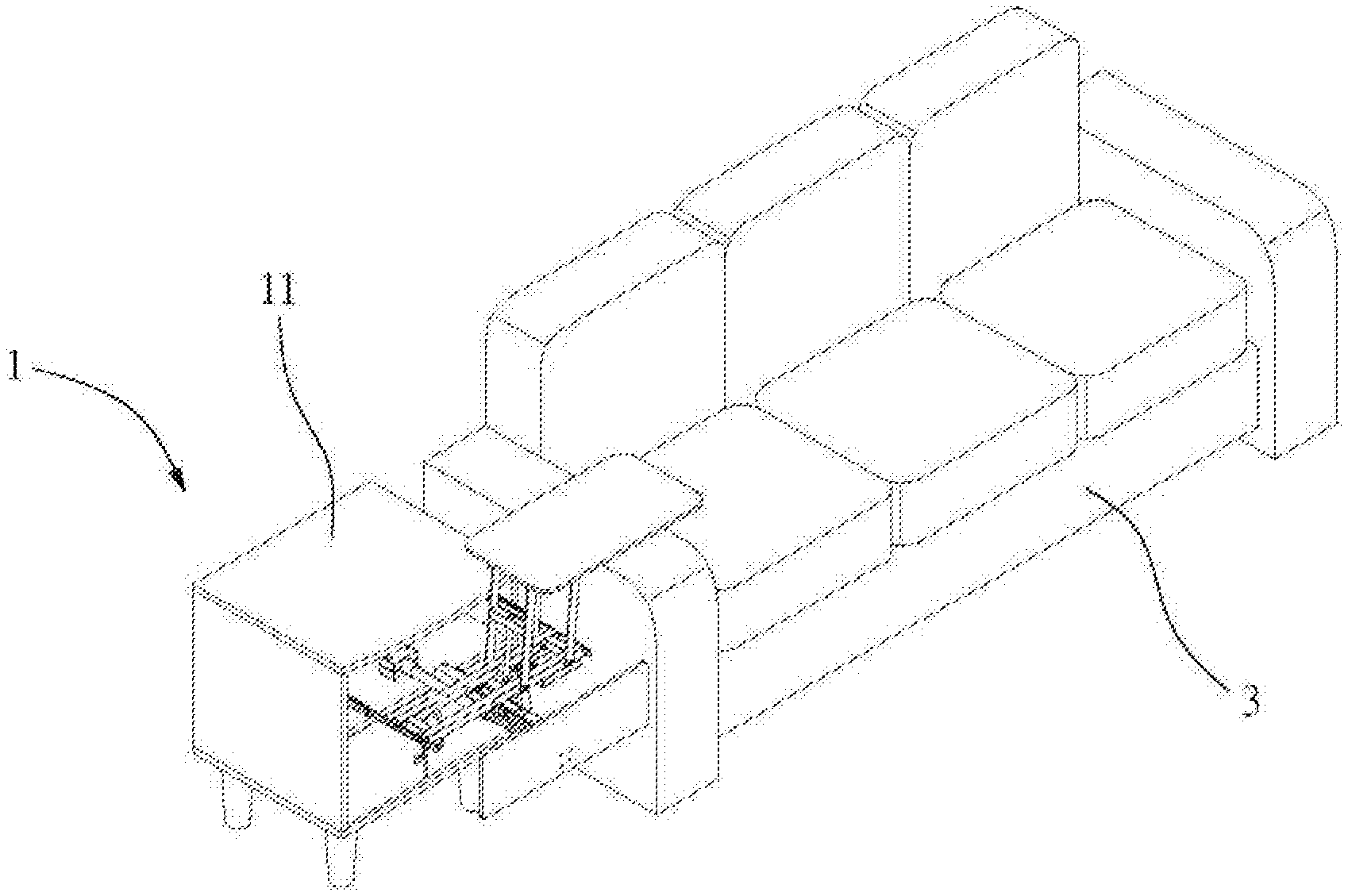
18. The side cabinet of claim 1, wherein the side cabinet is arranged beside a sofa.
Description
BACKGROUND OF THE INVENTION
1. Field of the Invention
[0001] The present invention relates to a house cabinet (or sideboard) and, more particularly, to a side cabinet (or side table assembly) with a telescopically arranged table.
2. Description of the Related Art
[0002] A conventional side cabinet is used for placing multiple items, such as keys, glasses, watches, reading lights or the like, to facilitate the user placing and using the items. The side cabinet has drawers to facilitate the user storing articles. However, the conventional side cabinet only has a single function. A conventional side table is available for a bed, a sofa or the like, to facilitate the user using electronic items, such as a smart phone, notebook computer, tablet or the like. In addition, the side table is arranged beside the bed, to facilitate a patient dining or working on the side table. However, the side table occupies a large space and cannot be folded, thereby causing inconvenience to the user when the side table is not in use. Thus, it is necessary to integrate the side cabinet and the side table.
BRIEF SUMMARY OF THE INVENTION
[0003] The primary objective of the present invention is to provide a side cabinet with a table that is expanded and contracted (or retracted) automatically.
[0004] In accordance with the present invention, there is provided a side cabinet comprising a cabinet body, a table, an electric cylinder, and an extension device. The cabinet body is provided with a support board. The electric cylinder is mounted on the support board of the cabinet body. The extension device includes two slide track units, a holding assembly, a telescopically arranged mechanism, and a linkage. The two slide track units are mounted on two opposite sides of the cabinet body. The telescopically arranged mechanism has a first end connected with the electric cylinder and a second end connected with a front cover board of the cabinet body. The holding assembly is mounted on and located above the telescopically arranged mechanism. The linkage is mounted on the holding assembly. The linkage includes at least one linking lever. The table is mounted on and located above the linkage. The holding assembly includes a spring holder, and a spring mounted in the spring holder. The spring of the holding assembly is used to lock the at least one linking lever of the linkage.
[0005] According to the primary advantage of the present invention, when the electric cylinder is operated, the telescopically arranged mechanism is driven to push the holding assembly, the linkage, and the table outward, and the spring is pulled outward to drive the linkage and the table to move upward, such that the table is moved transversely and lifted automatically.
[0006] According to another advantage of the present invention, the table is extended outward for use of the user, and is retracted into the cabinet body when not in use so as to save the storage space.
[0007] According to a further advantage of the present invention, the table is extended outward and retracted inward automatically, thereby facilitating the operator operating the table.
[0008] According to a further advantage of the present invention, the angle of the table is adjustable.
[0009] Further benefits and advantages of the present invention will become apparent after a careful reading of the detailed description with appropriate reference to the accompanying drawings.
BRIEF DESCRIPTION OF THE SEVERAL VIEWS OF THE DRAWING(S)
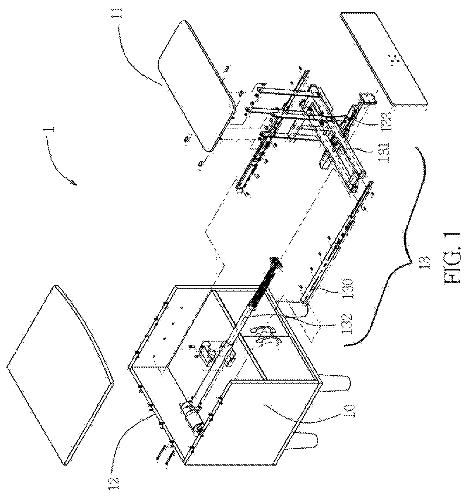
[0010] FIG. 1 is an exploded perspective view of a side cabinet in accordance with the preferred embodiment of the present invention.
[0011] FIG. 2 is a perspective view of the side cabinet in accordance with the preferred embodiment of the present invention.
[0012] FIG. 3 is an exploded perspective view of an extension device of the side cabinet in accordance with the preferred embodiment of the present invention.
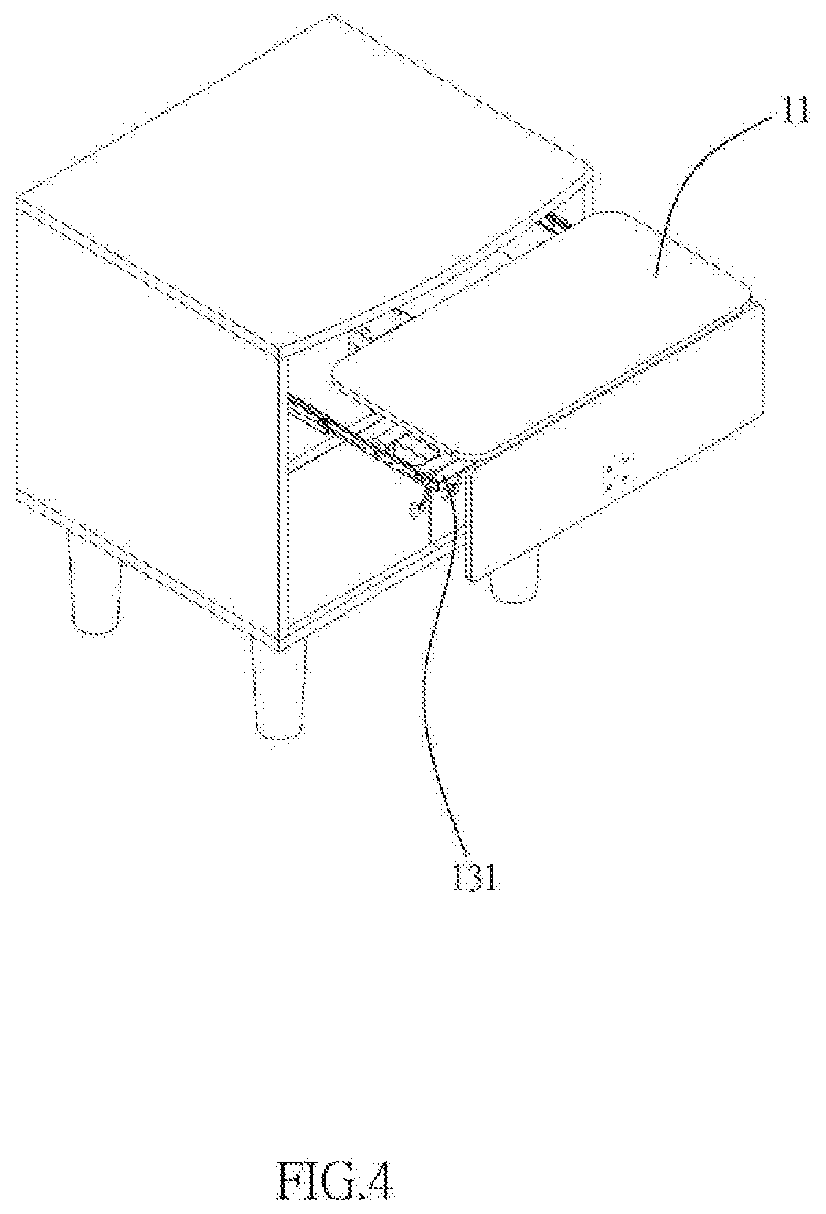
[0013] FIG. 4 is a perspective operational view of the side cabinet in accordance with the preferred embodiment of the present invention.
[0014] FIG. 5 is a schematic operational view of the side cabinet as shown in FIG. 4.
[0015] FIG. 6 is a schematic operational view of the side cabinet as shown in FIG. 5.
[0016] FIG. 7 is a perspective view of the side cabinet for a bed.
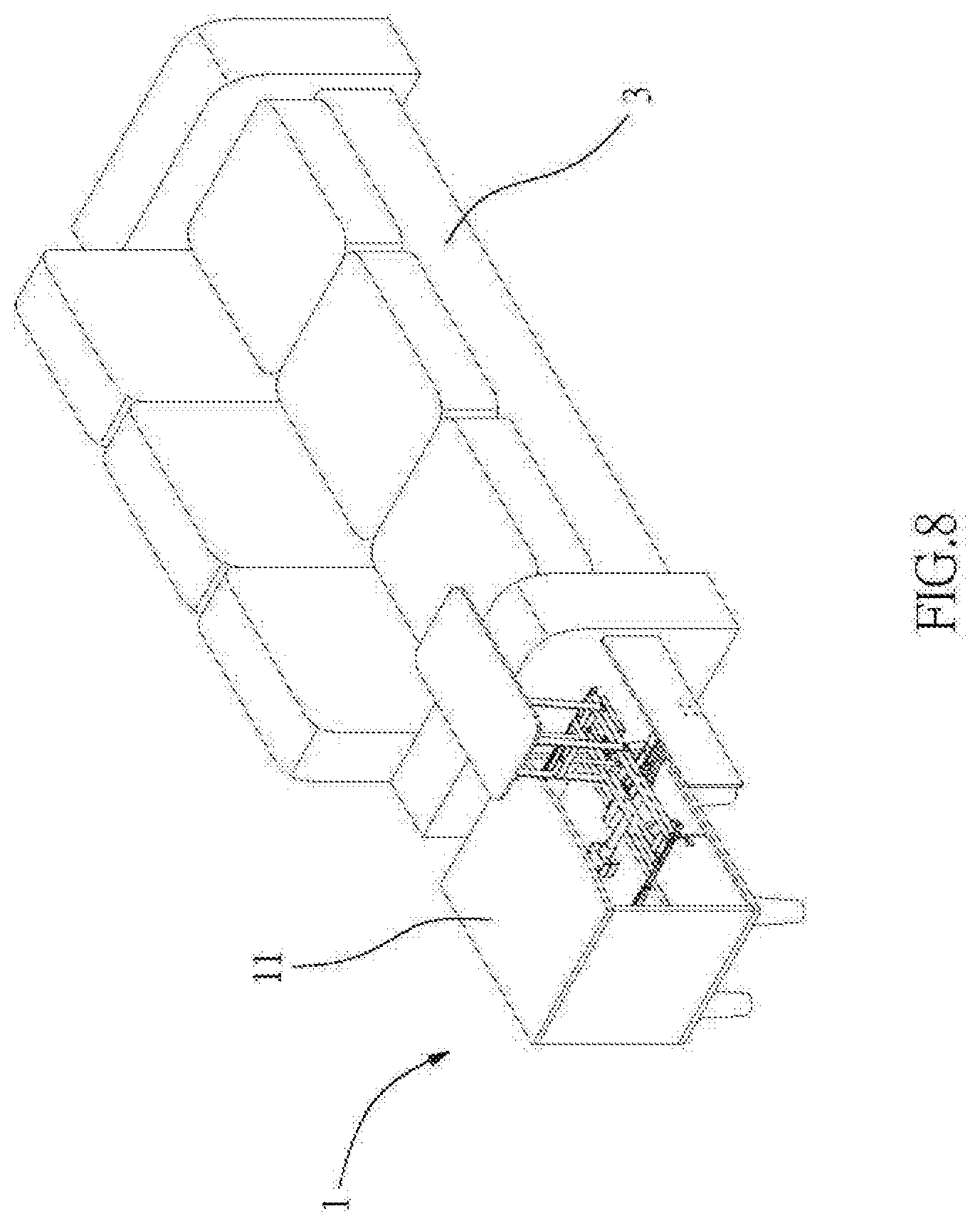
[0017] FIG. 8 is a perspective view of the side cabinet for a sofa.
[0018] FIG. 9 is a perspective view showing two angle adjusting devices of the side cabinet in accordance with another preferred embodiment of the present invention.
[0019] FIG. 10 is a perspective view showing operation of the angle adjusting devices of the side cabinet as shown in FIG. 9.
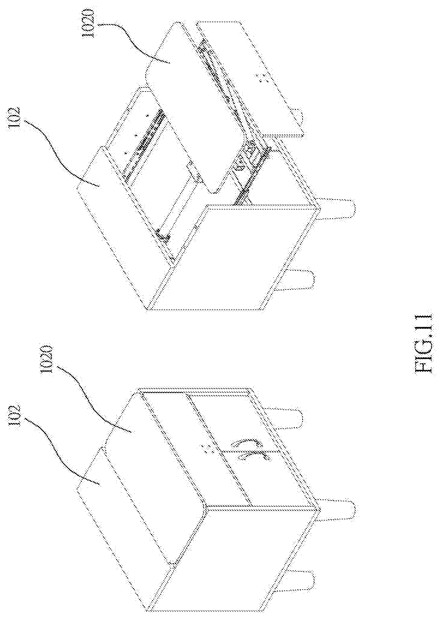
[0020] FIG. 11 is a perspective view of the side cabinet in accordance with a further preferred embodiment of the present invention.
[0021] FIG. 12 is a schematic operational view of the side cabinet as shown in FIG. 11.
DETAILED DESCRIPTION OF THE INVENTION
[0022] Referring to the drawings and initially to FIGS. 1-6, a side cabinet 1 in accordance with the preferred embodiment of the present invention comprises a cabinet body 10, a table 11, an electric cylinder 12, and an extension device 13.
[0023] The cabinet body 10 is provided with a support board (or dividing board or partition) 100. The electric cylinder 12 is mounted on the support board 100 of the cabinet body 10.
[0024] The extension device 13 includes two slide track units 130, a holding (or fixing or securing) assembly 131, a telescopically arranged mechanism 132, and a linkage 133. The two slide track units 130 are mounted (or secured) on two opposite sides of the cabinet body 10. The telescopically arranged mechanism 132 has a first end connected with the electric cylinder 12 and a second end connected with a front cover board 101 of the cabinet body 10. The holding assembly 131 is mounted on and located above the telescopically arranged mechanism 132. The linkage 133 is mounted on the holding assembly 131. The linkage 133 includes at least one linking lever 1330. The table 11 is mounted on and located above the linkage 133. The holding assembly 131 includes a spring holder 1310, and a spring 1311 mounted in the spring holder 1310. The spring 1311 of the holding assembly 131 is used to lock the at least one linking lever 1330 of the linkage 133.
[0025] In practice, when the spring 1311 of the holding assembly 131 is pulled and extended outward, the at least one linking lever 1330 of the linkage 133 is driven to move upward. On the contrary, when the spring 1311 of the holding assembly 131 is released and retracted inward, the at least one linking lever 1330 of the linkage 133 is driven to move downward.
[0026] In operation, referring to FIGS. 4-6 with reference to FIGS. 1-3, after the electric cylinder 12 is started, the telescopically arranged mechanism 132 is driven by the electric cylinder 12 to extend outward and to push the holding assembly 131 outward as shown in FIG. 4, such that the linkage 133 and the table 11 are moved outward. After the telescopically arranged mechanism 132 is extended outward, the spring holder 1310 of the holding assembly 131 is moved, and the spring 1311 is pulled outward, such that the at least one linking lever 1330 of the linkage 133 is driven to move upward as shown in FIG. 5. When the at least one linking lever 1330 of the linkage 133 is pivoted and moved upward successively, the table 11 is moved by the at least one linking lever 1330 of the linkage 133 and is moved transversely and lifted gradually until the table 11 is lifted to an uppermost position as shown in FIG. 6.
[0027] In the preferred embodiment of the present invention, when the table 11 is moved to the outermost position as shown in FIG. 4, the spring 1311 is pulled to reach a loosened state, such that the at least one linking lever 1330 of the linkage 133 is driven to move and pivot upward and outward as shown in FIG. 5, and is moved successively to the position as shown in FIG. 6.
[0028] In conclusion, when the electric cylinder 12 pushes the telescopically arranged mechanism 132, the holding assembly 131, the linkage 133, and the table 11, the spring 1311 is pulled outward, and the at least one linking lever 1330 of the linkage 133 is driven and moved upward, such that the table 11 is moved transversely and lifted. On the contrary, when the electric cylinder 12 pulls the telescopically arranged mechanism 132, the holding assembly 131, the linkage 133, and the table 11, the spring 1311 is contracted inward, and the at least one linking lever 1330 of the linkage 133 is driven and moved downward, such that the table 11 is moved transversely and folded.
[0029] Referring to FIG. 7 with reference to FIGS. 1-6, the side cabinet 1 is arranged beside a bed 2. In operation, after the electric cylinder 12 is started, the table 11 is moved outward and upward by interaction of the telescopically arranged mechanism 132, the holding assembly 131 and the linkage 133 of the extension device 13, until the table 11 is lifted to the uppermost position, such that the table 11 is used by the user. On the contrary, the electric cylinder 12 is operated reversely, so that the table 11 is retracted into the cabinet body 10. Thus, the table 11 is extended outward for use of the user and is retracted into the cabinet body 10 when not in use so as to save the storage space.
[0030] Referring to FIG. 8 with reference to FIGS. 1-6, the side cabinet 1 is arranged beside a sofa 3. In operation, after the electric cylinder 12 is started, the table 11 is moved outward and upward by interaction of the telescopically arranged mechanism 132, the holding assembly 131 and the linkage 133 of the extension device 13, until the table 11 is lifted to the uppermost position, such that the table 11 is used by the user. On the contrary, the electric cylinder 12 is operated reversely, so that the table 11 is retracted into the cabinet body 10. Thus, the table 11 is extended outward for use of the user and is retracted into the cabinet body 10 when not in use so as to save the storage space.
[0031] Referring to FIGS. 9 and 10 with reference to FIGS. 1-6, the side cabinet 1 further comprises at least one angle adjusting device 110 mounted on a bottom of the table 11 to adjust the angle of the table 11.
[0032] Accordingly, when the electric cylinder 12 is operated, the telescopically arranged mechanism 132 is driven to push the holding assembly 131, the linkage 133, and the table 11 outward, and the spring 1311 is pulled outward to drive the linkage 133 and the table 11 to move upward, such that the table 11 is moved transversely and lifted automatically. In addition, the angle of the table 11 is adjustable. Further, the table 11 is extended outward and retracted inward automatically, thereby facilitating the operator operating the table 11.
[0033] Referring to FIGS. 11 and 12 with reference to FIGS. 1-6, the table 1020 is disposed on a top of the cabinet body 10, and the side cabinet 1 further comprises an upper cover board 102 mounted on the top of the cabinet body 10 and juxtaposed to the table 1020. Thus, after the electric cylinder 12 is started, the table 1020 is detached from the upper cover board 102 and is moved outward and upward by interaction of the telescopically arranged mechanism 132, the holding assembly 131 and the linkage 133 of the extension device 13. On the contrary, when the electric cylinder 12 is operated reversely, the table 1020 is moved and returned to the original position, such that the table 1020 is juxtaposed to the upper cover board 102.
[0034] Although the invention has been explained in relation to its preferred embodiment(s) as mentioned above, it is to be understood that many other possible modifications and variations can be made without departing from the scope of the present invention. It is, therefore, contemplated that the appended claim or claims will cover such modifications and variations that fall within the scope of the invention.
* * * * *
D00000
D00001
D00002
D00003
D00004
D00005
D00006
D00007
D00008
D00009
D00010
D00011
D00012

XML
uspto.report is an independent third-party trademark research tool that is not affiliated, endorsed, or sponsored by the United States Patent and Trademark Office (USPTO) or any other governmental organization. The information provided by uspto.report is based on publicly available data at the time of writing and is intended for informational purposes only.
While we strive to provide accurate and up-to-date information, we do not guarantee the accuracy, completeness, reliability, or suitability of the information displayed on this site. The use of this site is at your own risk. Any reliance you place on such information is therefore strictly at your own risk.
All official trademark data, including owner information, should be verified by visiting the official USPTO website at www.uspto.gov. This site is not intended to replace professional legal advice and should not be used as a substitute for consulting with a legal professional who is knowledgeable about trademark law.