Negative Electrode Of Battery
LIN; Kun-Fung ; et al.
U.S. patent application number 17/005300 was filed with the patent office on 2020-12-17 for negative electrode of battery. The applicant listed for this patent is AUO Crystal Corporation. Invention is credited to Chih-Hung CHAN, Rong-Ruey JENG, Han-Tu LIN, Kun-Fung LIN.
| Application Number | 20200395601 17/005300 |
| Document ID | / |
| Family ID | 1000005051902 |
| Filed Date | 2020-12-17 |


View All Diagrams
| United States Patent Application | 20200395601 |
| Kind Code | A1 |
| LIN; Kun-Fung ; et al. | December 17, 2020 |
NEGATIVE ELECTRODE OF BATTERY
Abstract
A method for manufacturing silicon flakes includes steps as follows. A silicon material is contacted with a machining tool which includes at least one abrasive particle fixedly disposed thereon. The silicon material is scraped along a displacement path with respect to the machining tool to generate the silicon flakes having various particle sizes.
| Inventors: | LIN; Kun-Fung; (Taipei City, TW) ; JENG; Rong-Ruey; (Taoyuan City, TW) ; LIN; Han-Tu; (Hsinchu County, TW) ; CHAN; Chih-Hung; (Taoyuan City, TW) | ||||||||||
| Applicant: |
|
||||||||||
|---|---|---|---|---|---|---|---|---|---|---|---|
| Family ID: | 1000005051902 | ||||||||||
| Appl. No.: | 17/005300 | ||||||||||
| Filed: | August 27, 2020 |
Related U.S. Patent Documents
| Application Number | Filing Date | Patent Number | ||
|---|---|---|---|---|
| 15869061 | Jan 12, 2018 | 10797307 | ||
| 17005300 | ||||
| 14303620 | Jun 13, 2014 | 9905845 | ||
| 15869061 | ||||
| Current U.S. Class: | 1/1 |
| Current CPC Class: | H01M 4/1395 20130101; H01M 4/387 20130101; H01M 4/134 20130101; H01M 10/0525 20130101; H01M 4/364 20130101; H01M 4/386 20130101 |
| International Class: | H01M 4/1395 20060101 H01M004/1395; H01M 4/134 20060101 H01M004/134; H01M 4/36 20060101 H01M004/36; H01M 4/38 20060101 H01M004/38 |
Foreign Application Data
| Date | Code | Application Number |
|---|---|---|
| Sep 16, 2013 | TW | 102133528 |
Claims
1. A negative electrode of a battery, comprising: a plurality of silicon scraps with a flake shape; and an active material, wherein the silicon scraps are dispersed among the active material, and the active material comprises silicon carbide.
2. The negative electrode of the battery of claim 1, wherein a thickness of the silicon scrap is between 50 nm to 200 nm.
3. The negative electrode of the battery of claim 1, wherein a particle size of the silicon scrap is in a range of 50 nm to 9 .mu.m.
4. The negative electrode of the battery of claim 3, wherein the particle size of the silicon scrap is in a range of 50 nm to 300 nm.
5. The negative electrode of the battery of claim 1, wherein a thickness of the silicon scrap is between 50 nm to 200 nm, and a particle size of the silicon scrap is in a range of 50 nm to 300 nm.
6. The negative electrode of the battery of claim 1, wherein an amount of the silicon scraps is equal to or greater than 5 parts by weight based on 100 parts by weight of the negative electrode.
7. The negative electrode of the battery of claim 1, wherein the active material comprises a carbon material.
8. The negative electrode of the battery of claim 7, wherein the active material comprises a binder.
9. The negative electrode of the battery of claim 1, wherein the active material comprises a plurality of kinds of carbon materials.
10. The negative electrode of the battery of claim 7, wherein the active material comprises graphite.
11. The negative electrode of the battery of claim 1, wherein the active material comprises metal.
12. The negative electrode of the battery of claim 11, wherein the metal is nickel.
13. The negative electrode of the battery of claim 8, wherein the silicon scrap has a first surface along a long axis direction, and the first surface of the silicon scrap is bonding with the binder.
14. The negative electrode of the battery of claim 13, further comprising a conductive agent mixing with the silicon scraps and the binder.
15. The negative electrode of the battery of claim 1, wherein the active material comprises a binder.
16. The negative electrode of the battery of claim 15, wherein the silicon scrap has a first surface along a long axis direction, and the first surface of the silicon scrap is bonding with the binder.
17. The negative electrode of the battery of claim 16, further comprising a conductive agent mixing with the silicon scraps and the binder.
18. The negative electrode of the battery of claim 15, wherein the active material comprises a plurality of kinds of carbon materials.
19. The negative electrode of the battery of claim 18, wherein the active material comprises graphite.
20. The negative electrode of the battery of claim 18, wherein the active material comprises nickel.
Description
RELATED APPLICATIONS
[0001] The present application is a continuation of the application Ser. No. 15/869,061, filed Jan. 12, 2018, which is a continuation of the application Ser. No. 14/303,620, filed Jun. 13, 2014, U.S. Pat. No. 9,905,845 issued on Feb. 27, 2018, which claims priority to Taiwan Application Serial Number 102133528, filed Sep. 16, 2013, which are herein incorporated by reference.
BACKGROUND
Technical Field
[0002] The present disclosure relates to a battery material and a method for manufacturing the same. More particularly, the present disclosure relates to an electrode material of a lithium ion battery and a method for manufacturing the same.
Description of Related Art
[0003] In recent years, with the development of 3C electronics, lightweight, mobile and high-energy batteries have attracted considerable attention. Among the high-energy batteries, lithium ion batteries have developed most maturely and been widely applied to portable electronics. For example, a smart phone evolves not only toward large size color screen, but also with more and more complicated functionalities of photo shooting and music playing. As a result, a demand for lightweight high-energy batteries is increasing. How to increase a capacity and a cycle life of the lithium ion batteries has become an important subject.
[0004] In the known technical solutions, a commonly used negative electrode material of the lithium ion batteries is a graphite-based material, such as a graphite carbon material. The graphite-based material has an excellent charge and discharge capacity, and no dendritic structure is generated, so that the graphite-based material is safer in performance. However, the structure of the negative electrode made of graphite-based material is spoiled due to the reversibly insertion and detachment of lithium ions after a number of charging and discharging cycles. Accordingly, the cycle life of the lithium ion batteries is influenced. Furthermore, a theoretical charge capacity of graphite is only about 372 mAh/g, and the development of the lithium ion batteries is limited thereby.
[0005] A lot of researches for improving the negative electrode material of the lithium ion batteries have been provided. For example, silicon material is mixed into the negative electrode of the lithium ion batteries. A theoretical capacity of the silicon material is about 4200 mAh/g, which is the highest among the materials applied to the negative electrode of the lithium ion batteries. However, a phase change is caused by the reversibly insertion and detachment of lithium ions, and a volume expansion is generated thereby. The volume expansion is so large that the cycling stability and irreversibility of the silicon-containing negative electrode of the lithium ion batteries are seriously influenced.
[0006] Minimizing the particle sizes of the silicon material is one of the solutions for controlling the volume expansion. For example, the particle sizes of the silicon material are minimized to the range of 10.about.300 nm. Although it is common to control the volume expansion by minimizing the particle sizes of the silicon material to the nanoscale. The silicon material in the form of nanoscale particles is very expensive. Also, a significant irreversible capacity is caused due to a larger surface area of the nanoscale particles. Importantly, the nanoscale particles with similar sizes and shapes tend to aggregate with each other to form larger particles, and the process of uniformly mixing the materials to form the negative electrode becomes more difficult.
[0007] A columnar silicon material for reducing the volume expansion is disclosed. The particle sizes of the columnar silicon material are in a range of 10 .mu.m to 800 .mu.m. The columnar silicon material is formed by a chemical method including an etching step and a nucleating step. However, the formed columnar silicon material has to be removed from a substrate, such that the chemical method has a high cost and low manufacturing rate. Furthermore, the particle sizes of the columnar silicon material are limited by the chemical method, and the consistency of the sizes of the columnar silicon material intensifies the aggregation of the columnar silicon material. Therefore, a subsequent dispersion process is required for the columnar silicon material.
[0008] Given the above, how to obtain an environmental friendly silicon material, which is low cost and the volume expansion thereof can be well controlled, has become the important subject for the relevant industry of the lithium ion batteries.
SUMMARY
[0009] According to one aspect of the present disclosure, a method for manufacturing silicon flakes includes steps as follows. A silicon material is contacted with a machining tool. The machining tool includes at least one abrasive particle fixedly disposed thereon. The silicon material is scraped along a displacement path with respect to the machining tool to generate a plurality of silicon flakes having various particle sizes.
[0010] According to another aspect of the present disclosure, a method for manufacturing a silicon-containing negative electrode of a lithium ion battery includes steps as follows. A silicon material is contacted with a machining tool. The machining tool includes at least one abrasive particle fixedly disposed thereon. The silicon material is scraped along a displacement path with respect to the machining tool to generate a plurality of silicon flakes having various particle sizes. The silicon flakes are consolidated to form the silicon-containing negative electrode of the lithium ion battery.
[0011] According to further another aspect of the present disclosure, a silicon-containing negative electrode of a lithium ion battery is disclosed. The silicon-containing negative electrode of the lithium ion battery is manufactured by the aforementioned method. The silicon-containing negative electrode of the lithium ion battery includes the silicon flakes and an active material. An amount of the silicon flakes is equal to or greater than 5 parts by weight based on 100 parts by weight of the silicon-containing negative electrode. The silicon flakes have various particle sizes in a range of 50 nm to 9 .mu.m. The active material is graphite, a metal element or a metal compound.
[0012] According to yet another aspect of the present disclosure, a silicon-containing negative electrode of a lithium ion battery is disclosed. The silicon-containing negative electrode of the lithium ion battery is manufactured by the aforementioned method. The silicon-containing negative electrode is substantially composed of the silicon flakes. The silicon flakes have various particle sizes in a range of 50 nm to 9 .mu.m.
BRIEF DESCRIPTION OF THE DRAWINGS
[0013] The disclosure can be more fully understood by reading the following detailed description of the embodiment, with reference made to the accompanying drawings as follows:
[0014] FIG. 1 is a flow diagram showing a method for manufacturing a silicon-containing negative electrode of a lithium ion battery according to one embodiment of the present disclosure;
[0015] FIG. 1A is a SEM (scanning electron microscope) photomicrograph of a surface of a silicon material after constantly scraped by a machining tool according to the method in FIG. 1 taken at 20 times magnification;
[0016] FIG. 1B is a SEM photomicrograph of the surface of the silicon material in FIG. 1A taken at 50 times magnification;
[0017] FIG. 1C is a SEM photomicrograph of the surface of the silicon material in FIG. 1A taken at 100 times magnification;
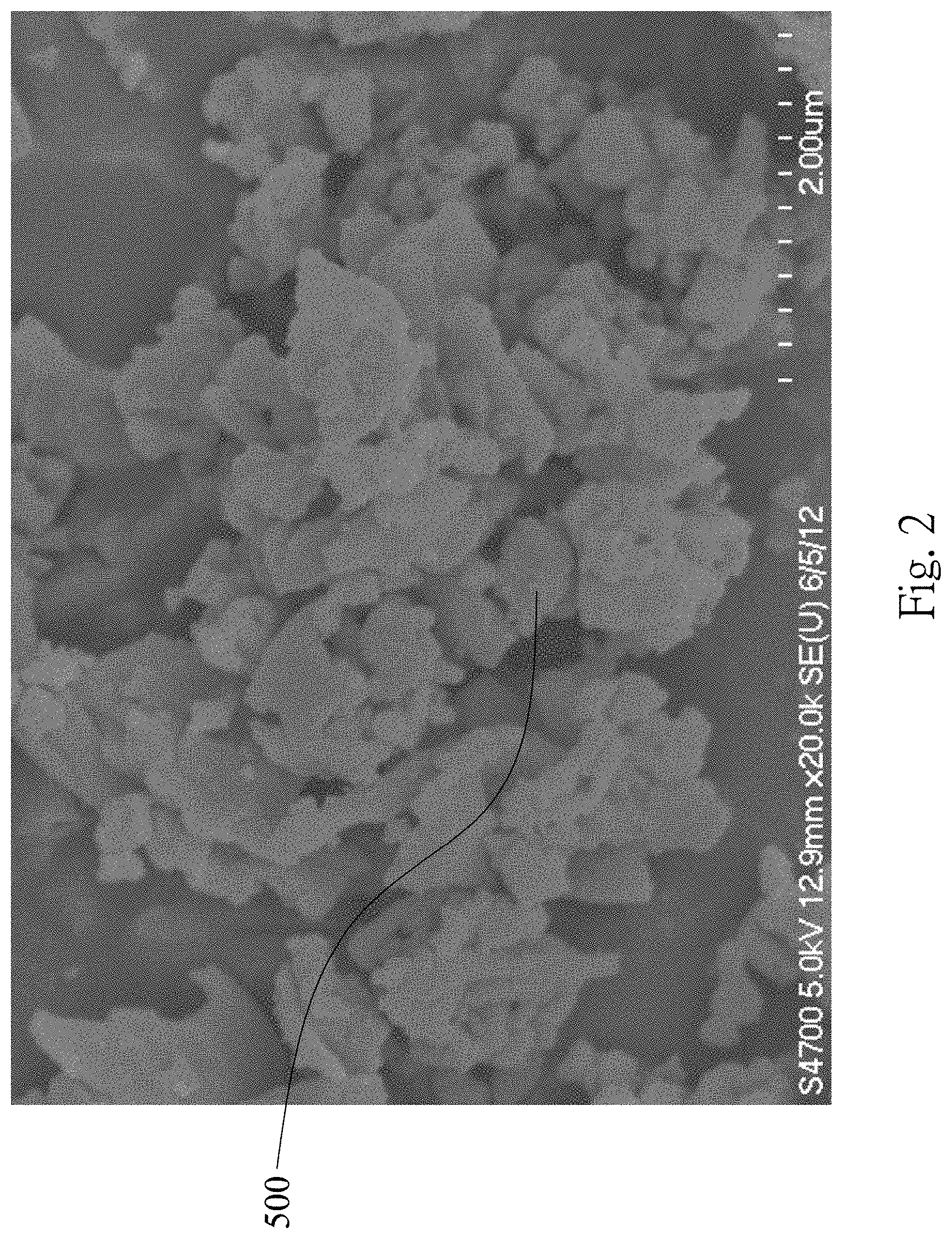
[0018] FIG. 2 is a SEM photomicrograph of a plurality of silicon flakes manufactured by the method in FIG. 1;
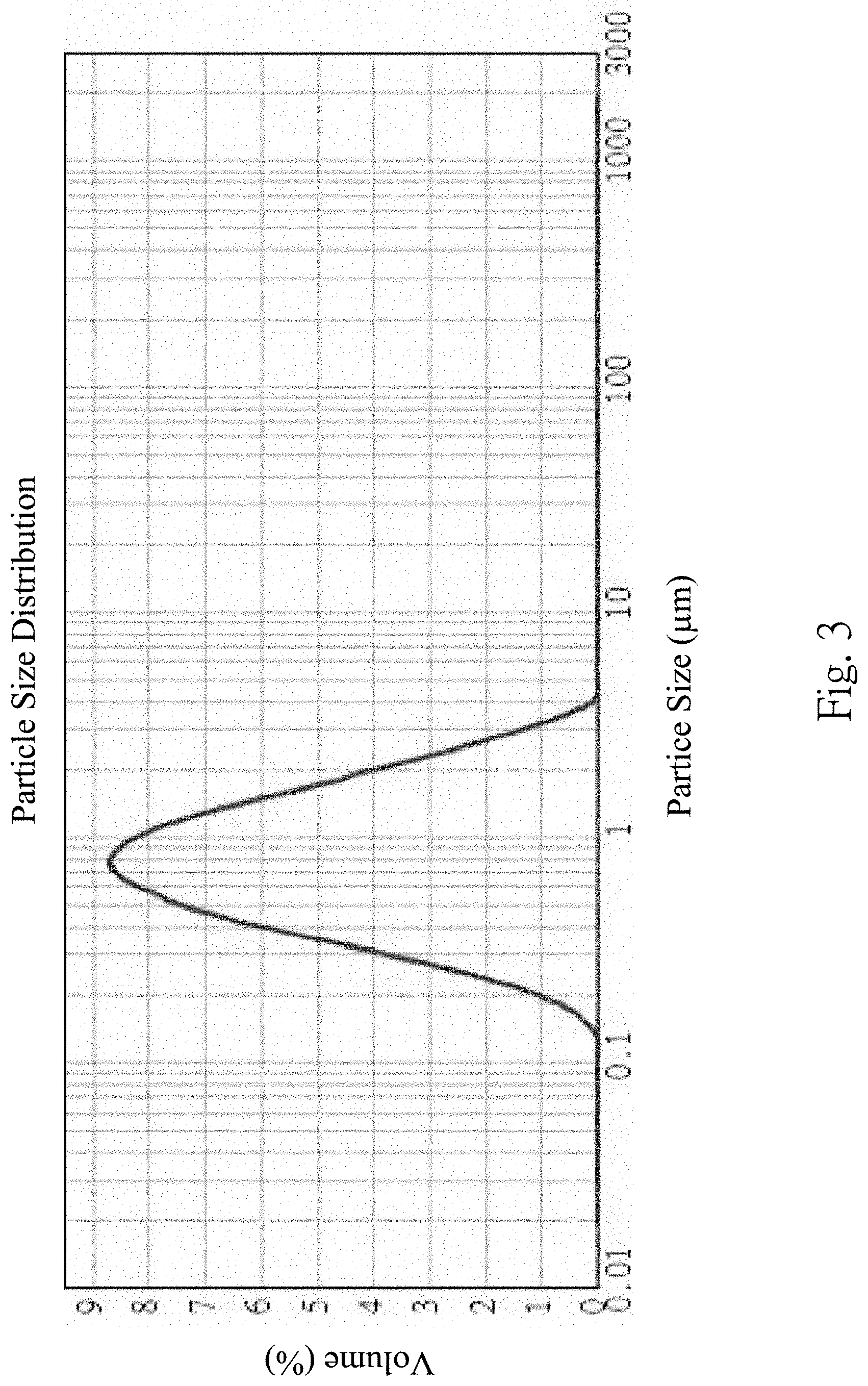
[0019] FIG. 3 shows a particle size distribution of the silicon flakes manufactured by the method in FIG. 1;
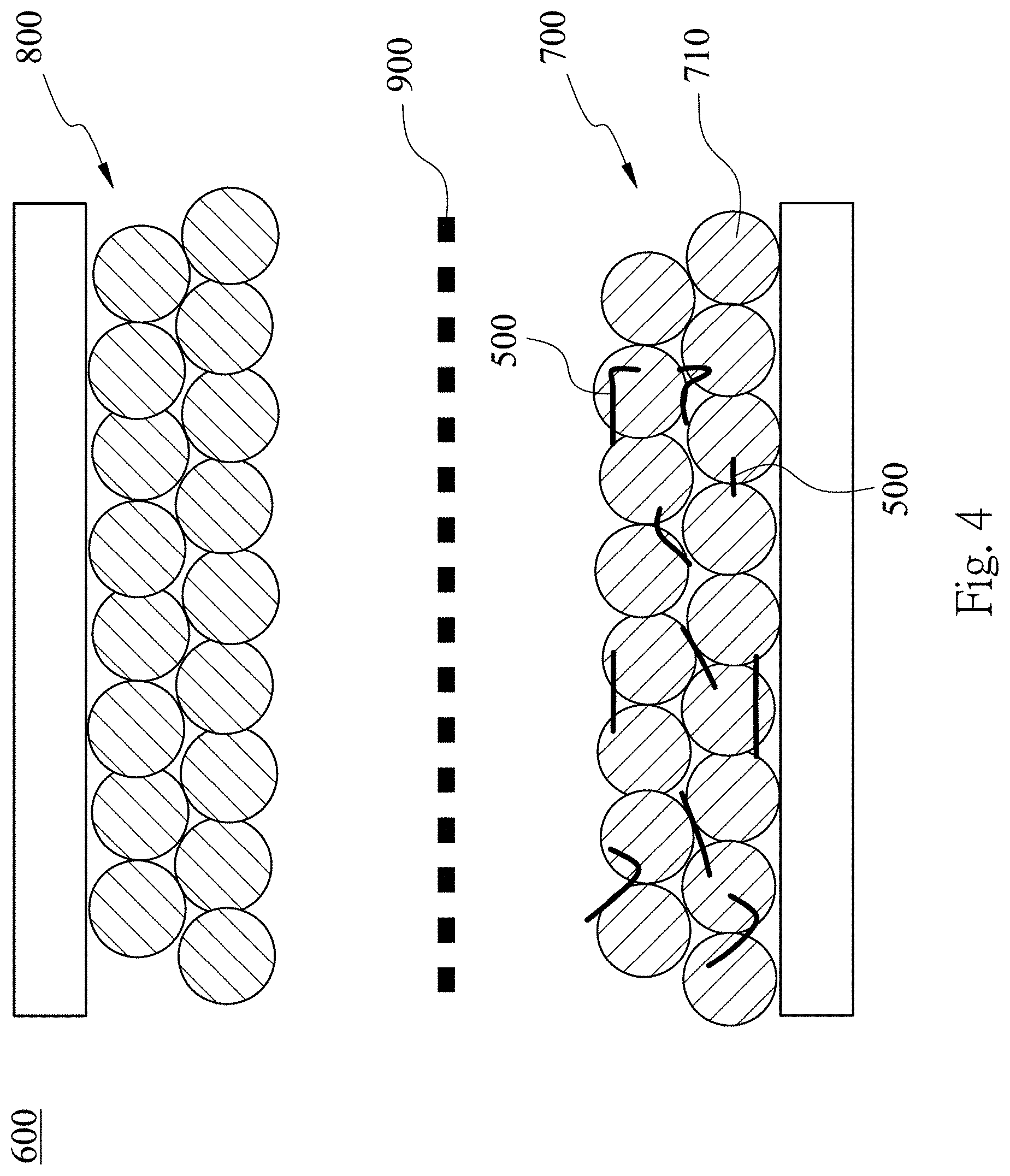
[0020] FIG. 4 is a schematic view of a silicon-containing negative electrode of a lithium ion battery according to one embodiment of the present disclosure;
[0021] FIG. 5 is a partial enlarged schematic view showing a microscopic state of FIG. 4;
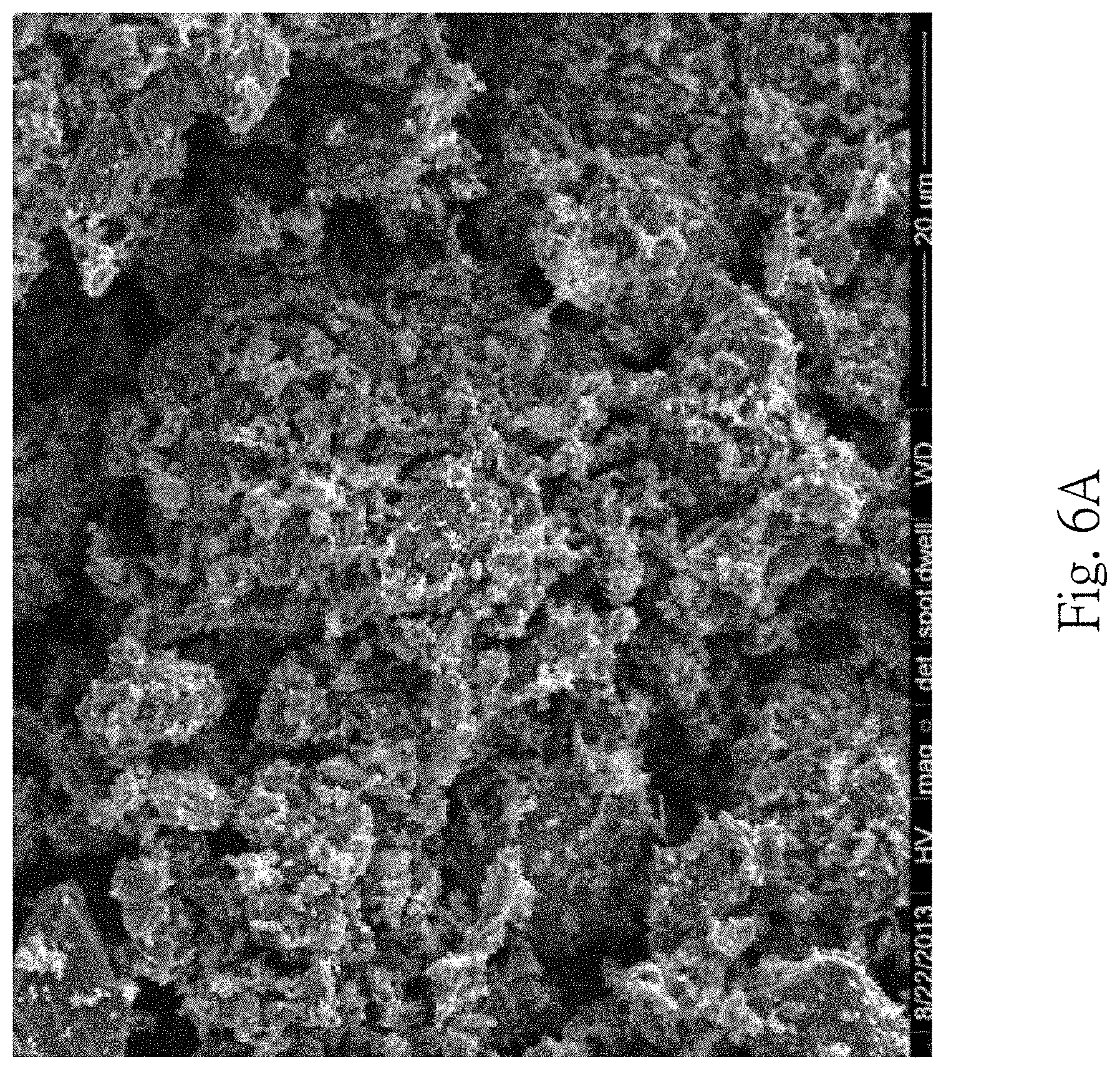
[0022] FIG. 6A is a SEM photomicrograph of a silicon-containing negative electrode of a lithium ion battery according to the 1st example of the present disclosure;
[0023] FIG. 6B shows Coulombic efficiency and charge/discharge capacity versus cycle number of the lithium ion battery according to the 1st example;
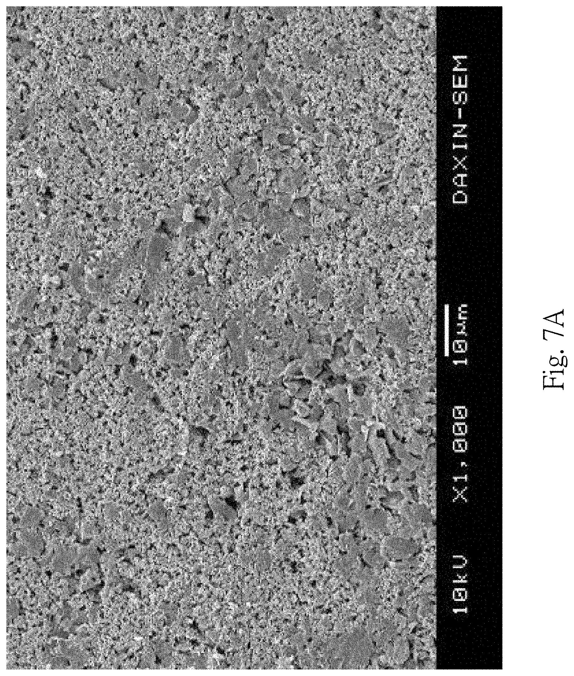
[0024] FIG. 7A is a SEM photomicrograph of a silicon-containing negative electrode of a lithium ion battery according to the 2nd example of the present disclosure;
[0025] FIG. 7B shows voltage versus capacity of the 1st cycle to the 5th cycle of the lithium ion battery according to the 2nd example;
[0026] FIG. 7C shows Coulombic efficiency and charge/discharge capacity versus cycle number of the lithium ion battery according to the 2nd example;
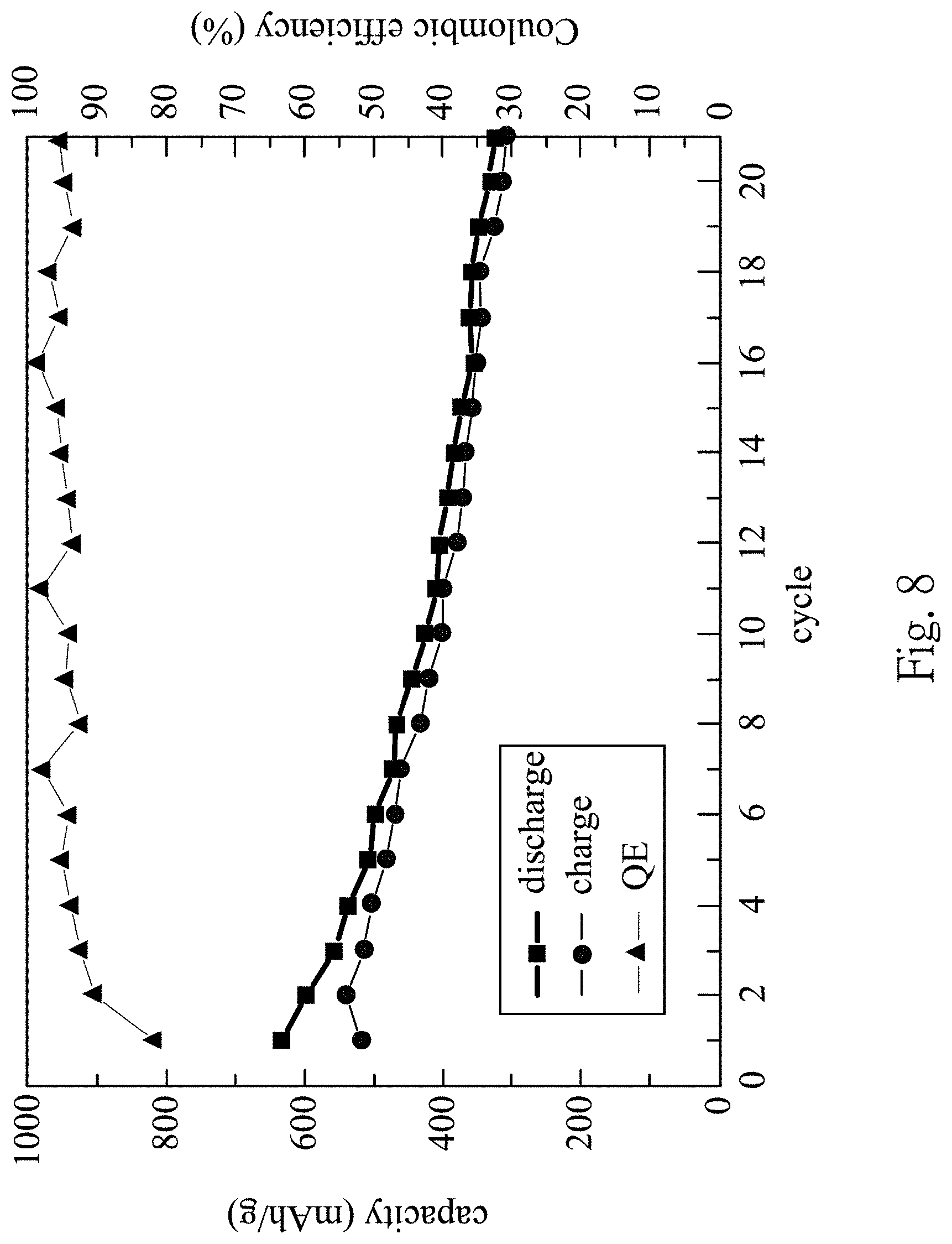
[0027] FIG. 8 shows Coulombic efficiency and charge/discharge capacity versus cycle number of the lithium ion battery according to the 3rd example;
[0028] FIG. 9 shows Coulombic efficiency and charge/discharge capacity versus cycle number of the lithium ion battery according to the 4th example; and
[0029] FIG. 10 shows Coulombic efficiency and charge/discharge capacity versus cycle number of the lithium ion battery according to the 5th example.
DETAILED DESCRIPTION
[0030] <Method for Manufacturing Silicon Flakes of a Silicon-Containing Negative Electrode of a Lithium Ion Battery>
[0031] FIG. 1 is a flow diagram showing a method for manufacturing a silicon-containing negative electrode 700 of a lithium ion battery 600 according to one embodiment of the present disclosure. FIG. 1A-FIG. 1C are SEM photomicrographs of a surface of a silicon material 400 after constantly scraped by a machining tool according to the method in FIG. 1, and FIG. 1A-FIG. 1C are taken at 20 times magnification, 50 times magnification and 100 times magnification respectively. FIG. 2 is a SEM photomicrograph of a plurality of silicon flakes 500 manufactured by the method in FIG. 1. FIG. 3 shows a particle size distribution of the silicon flakes 500 manufactured by the method in FIG. 1. FIG. 4 is a schematic view of the silicon-containing negative electrode 700 of the lithium ion battery 600 according to one embodiment of the present disclosure.
[0032] The method for manufacturing the silicon-containing negative electrode 700 of the lithium ion battery 600 includes steps as follows.
[0033] In Step 100, the silicon material 400 is contacted with the machining tool, wherein the machining tool includes a plurality of abrasive particle fixedly disposed thereon. For examples, the machining tool can be a wire saw, a band saw or a grinding disc. The abrasive particles can be natural diamonds, artificial diamonds, cubic boron nitride, silicon carbide, aluminum oxide or cerium oxide
[0034] In Step 200, the silicon material 400 is scraped along a displacement path A (shown in FIG. 1A, FIG. 1B and FIG. 1C) with respect to the machine tool to generate the silicon flakes 500 having various particle sizes. The displacement path A is a straight line. As shown in FIG. 1A, FIG. 1B and FIG. 1C, a large number of the silicon flakes 500 are generated, and the silicon flakes 500 have various particle sizes. As shown in FIG. 2, a thickness of each of the silicon flakes 500 along a short axis thereof is 50 nm to 200 nm. The aforementioned "a short axis" means that each of the silicon flakes 500 is substantially an oblong flake and has a thickness, and the short axis is along a thickness direction of the oblong flake. As shown in FIG. 3, a range of the particle sizes of the silicon flakes 500 is about 50 nm to 9 .mu.m, and the particle sizes of the silicon flakes 500 are concentrated in a range of 300 nm to 2 .mu.m.
[0035] Furthermore, the displacement path A is not limited to a straight line. In another embodiment, the displacement path A can be a curve line. When the silicon material 400 is repeatedly scraped by the machining tool, the machining tool can back and forth scrape the silicon material 400 along the displacement path, or the machining tool can scrape the silicon material 400 along the displacement path in one way.
[0036] In Step 300, the silicon flakes 500 are consolidated to form the silicon-containing negative electrode 700 of the lithium ion battery 600. Therefore, the manufacturing costs of the silicon-containing negative electrode 700 of the lithium ion battery 600 are reduced via the mechanical method for manufacturing the silicon flakes 500, and the problem of volume expansion is preferably resolved via the inconsistencies of the particle sizes and shapes of the silicon flakes 500. Furthermore, the aggregation characteristic of the silicon flakes 500 can be reduced due to the inconsistencies of the particle sizes and shapes of the silicon flakes 500.
[0037] In Step 300, the silicon flakes 500 are used to form the silicon-containing negative electrode 700 of the lithium ion battery 600, which is only one of the applications of the silicon flakes 500. In other embodiments, the silicon flakes 500 can be used to manufacture other kinds of batteries.
<Method for Manufacturing a Silicon-Containing Negative Electrode of A Lithium Ion Battery>
[0038] Please refer to FIG. 4, FIG. 5 and FIG. 6A. FIG. 5 is a partial enlarged schematic view showing a microscopic state of FIG. 4. FIG. 6A is a SEM photomicrograph of a silicon-containing negative electrode 700 of a lithium ion battery 600 according to the 1st example of the present disclosure. In FIG. 4, the lithium ion battery 600 includes the silicon-containing negative electrode 700, a positive electrode 800 and a separator 900. The silicon-containing negative electrode 700 is opposite to the positive electrode 800, and the separator 900 is disposed between the silicon-containing negative electrode 700 and the positive electrode 800. The silicon-containing negative electrode 700 is manufactured by the aforementioned method. Specifically, the silicon-containing negative electrode 700 includes the silicon flakes 500, binders 720, conductive agents and active materials 710. The active materials 710 can be graphite, all kinds of carbon materials, a metal element or a metal compound. The metal element can be but not limited to tin, nickel, titanium, manganese, copper, magnesium and a combination thereof. The metal compound can be but not limited to titanium carbide, silicon carbide or titanate. In the 1st example, the active materials 710 are graphite. The silicon flakes 500, binders 720, conductive agents and active materials 710 are mixed in an appropriate proportion so as to form a uniform mixture, and the uniform mixture is coated on a copper electrode plate so as to form the silicon-containing negative electrode 700. The electrolyte used in the lithium ion battery 600 can be but not limited to LiPF.sub.6. The binders 720 can be CMC (carboxymethyl cellulose), SBR (styrene-butadiene rubber) or PAA (polyacrylic acid). The conductive agents can be but not limited to KS-6 or Super-P.
[0039] Based on 100 parts by weight of the silicon-containing negative electrode 700, an amount of the silicon flakes 500 is equal to or greater than 5 parts by weight. Preferably, based on 100 parts by weight of the silicon-containing negative electrode 700, the amount of the silicon flakes 500 is 5 parts by weight to 80 parts by weight. More preferably, based on 100 parts by weight of the silicon-containing negative electrode 700, the amount of the silicon flakes 500 is 10 parts by weight to 20 parts by weight.
[0040] In the silicon-containing negative electrode 700, the silicon flakes 500 are dispersed among the active materials 710. Although a silicon material has a high theoretical capacity which is up to 4200 mAh/g. However, the problem of volume expansion exited in the silicon material endangers the performance of the silicon material. The problem of volume expansion has been overcome by the shapes and particle sizes of the silicon flakes 500 according to the present disclosure. The range of the particle sizes of the silicon flakes 500 according to the present disclosure is 50 nm to 9 .mu.m, and the thickness of each of the silicon flakes 500 along the short axis thereof is 50 nm to 200 nm. As a result, the amount of volume expansion (as the expanding directions indicated by the arrows shown in FIG. 5) along a long axis direction is reduced. Furthermore, each of the silicon flakes 500 has a larger surface for bonding with the binder 720. Therefore, the generation of the cracks of the silicon-containing negative electrode 700 due to volume expansion is reduced, and the capacity of the lithium ion battery 600 is increased accordingly. In other words, the capacity and the lifetime of the lithium ion battery 600 are both increased.
[0041] <Experiment Result of Lithium Ion Battery--1st Example>
[0042] Please refer to FIG. 6A and FIG. 6B. FIG. 6B shows Coulombic efficiency and charge/discharge capacity versus cycle number of the lithium ion battery 600 according to the 1st example.
[0043] In the 1st example, based on 100 parts by weight of the silicon-containing negative electrode 700, an amount of the silicon flakes 500 is equal to 12 parts by weight. In FIG. 6B, the capacity of the lithium ion battery 600 is measured by a battery automation test system, and the model number of the battery automation test system is BAT-750B. The charge-discharge tests are conducted for 40 cycles, and the charge-discharge tests are conducted under a fixed charge/discharge rate of 0.1C and a cut-off voltage of 20 mV.about.1.2 V. The relationships between voltage and time are recorded by a computer. In FIG. 6B, the QE value of the 1st cycle is 77.7%. The charge capacity of the 1st cycle is 413.8 mAh/g, the charge capacity of the 37th cycle is 450.7 mAh/g, and the capacity retention of the 37th cycle is up to 108.9%.
[0044] <Experiment Result of Lithium Ion Battery--2nd Example>
[0045] FIG. 7A is a SEM photomicrograph of a silicon-containing negative electrode 700 of a lithium ion battery 600 according to the 2nd example of the present disclosure. FIG. 7B shows voltage versus capacity of the 1st cycle to the 5th cycle of the lithium ion battery 600 according to the 2nd example. FIG. 7C shows Coulombic efficiency and charge/discharge capacity versus cycle number of the lithium ion battery 600 according to the 2nd example.
[0046] In the 2nd example, based on 100 parts by weight of the silicon-containing negative electrode 700, an amount of the silicon flakes 500 is equal to 60 parts by weight. In FIG. 7B and FIG. 7C, the capacity of the lithium ion battery 600 is measured by a battery automation test system, and the model number of the battery automation test system is BAT-750B. In FIG. 7B and FIG. 7C, the charge-discharge tests are conducted for 5 cycles, and the charge-discharge tests are conducted under a fixed charge/discharge rate of 0.1C, and a discharge cut-off voltage of 20 mV, and a charge cut-off voltage of 1200 mV. The relationships between voltage and time are recorded by a computer. In FIG. 7C, the QE value of the 1st cycle is 88%. The discharge capacity of the 1st cycle is up to 3627 mAh/g, and the charge capacity of the 5th cycle is still up to 2116 mAh/g.
[0047] <Experiment Result of Lithium Ion Battery--3rd Example>
[0048] FIG. 8 shows Coulombic efficiency and charge/discharge capacity versus cycle number of a lithium ion battery 600 according to the 3rd example. In the 3rd example, based on 100 parts by weight of the silicon-containing negative electrode 700, an amount of the silicon flakes 500 is equal to 15 parts by weight. Specifically, based on 100 parts by weight of the silicon-containing negative electrode 700, the amount of the silicon flakes 500 is equal to 15 parts by weight, an amount of an active material 710 (in the example, the active material 710 is carbon) is equal to 75 parts by weight, and an amount of a binder 730 is equal to 10 parts by weight. In FIG. 8, the capacity of the lithium ion battery 600 is measured by a battery automation test system, and the model number of the battery automation test system is BAT-750B. In FIG. 8, the charge-discharge tests are conducted under a fixed charge/discharge rate of 0.1C, and a cut-off voltage of 20 mV-1.2 V. The relationships between voltage and time are recorded by a computer. In FIG. 8, the charge capacity of the 1st cycle is 517 mAh/g, the discharge capacity of the 1st cycle is 634 mAh/g, and the QE value of the 1st cycle is 81.5%. The charge capacity of the 2nd cycle is 540 mAh/g, the discharge capacity of the 2nd cycle is 598 mAh/g, and the QE value of the 2nd cycle is 90.3%. Furthermore, the charge capacity and the discharge capacity of the 21th cycle are all greater than 300 mAh/g. It is obvious that an excellent capacity can be provided by the lithium ion battery 600 according to the present disclosure after a number of cycles.
[0049] <Experiment Result of Lithium Ion Battery--4th Example>
[0050] FIG. 9 shows Coulombic efficiency and charge/discharge capacity versus cycle number of a lithium ion battery 600 according to the 4th example. In the 4th example, based on 100 parts by weight of the silicon-containing negative electrode 700, an amount of the silicon flakes 500 is equal to 30 parts by weight. Specifically, based on 100 parts by weight of the silicon-containing negative electrode 700, the amount of the silicon flakes 500 is equal to 30 parts by weight, an amount of an active material 710 (in the example, the active material 710 is carbon) is equal to 60 parts by weight, and an amount of a binder 730 is equal to 10 parts by weight. In FIG. 9, the capacity of the lithium ion battery 600 is measured by a battery automation test system, and the model number of the battery automation test system is BAT-750B. In FIG. 9, the charge-discharge tests are conducted under a fixed charge/discharge rate of 0.1C, and a cut-off voltage of 20 mV-1.2 V. The relationships between voltage and time are recorded by a computer. In FIG. 9, the charge capacity of the 1st cycle is 860 mAh/g, the discharge capacity of the 1st cycle is 1015 mAh/g, and the QE value of the 1st cycle is 84.7%. The charge capacity of the 2nd cycle is 878 mAh/g, the discharge capacity of the 2nd cycle is 927 mAh/g, and the QE value of the 2nd cycle is 94.7%. Furthermore, the charge capacity and the discharge capacity of the 21st cycle are all greater than 500 mAh/g. It is obvious that an excellent capacity can be provided by the lithium ion battery 600 according to the present disclosure after a number of cycles.
[0051] <Experiment Result of Lithium Ion Battery--5th Example>
[0052] FIG. 10 shows Coulombic efficiency and charge/discharge capacity versus cycle number of a lithium ion battery 600 according to the 5th example. In the 5th example, based on 100 parts by weight of the silicon-containing negative electrode 700, an amount of the silicon flakes 500 is equal to 60 parts by weight. Specifically, based on 100 parts by weight of the silicon-containing negative electrode 700, the amount of the silicon flakes 500 is equal to 60 parts by weight, an amount of an active material 710 (in the example, the active material 710 is carbon) is equal to 30 parts by weight, and an amount of a binder 730 is equal to 10 parts by weight. In FIG. 10, the capacity of the lithium ion battery 600 is measured by a battery automation test system, and the model number of the battery automation test system is BAT-750B. In FIG. 10, the charge-discharge tests are conducted under a fixed charge/discharge rate of 0.1C, and a cut-off voltage of 20 mV-1.2 V. The relationships between voltage and time are recorded by a computer. In FIG. 10, the charge capacity of the 1st cycle is 1726 mAh/g, the discharge capacity of the 1st cycle is 2086 mAh/g, and the QE value of the 1st cycle is 82.7%. The charge capacity of the 2nd cycle is 1419 mAh/g, the discharge capacity of the 2nd cycle is 1699 mAh/g, and the QE value of the 2nd cycle is 83.5%. Furthermore, the charge capacity and the discharge capacity of the 21st cycle are all greater than 600 mAh/g. It is obvious that an excellent capacity can be provided by the lithium ion battery 600 according to the present disclosure after a number of cycles.
[0053] Please refer to Table 1.
TABLE-US-00001 TABLE 1 Example 3rd 4th 5th amount of the silicon 15 30 60 flakes (wt %) cycle 1st 2nd 1st 2nd 1st 2nd discharge capacity 634 598 1015 927 2086 1699 (mAh/g) charge capacity (mAh/g) 517 540 860 878 1726 1419 Coulombic efficiency (%) 81.5 90.3 84.7 94.7 82.7 83.5
[0054] As shown in Table 1, the Coulombic efficiency of the 1st cycle doesn't decrease with the increase of the amount of the silicon flakes 500. When a negative electrode of a conventional lithium ion battery is added with spherical silicon powders in micron scale, the Coulombic efficiency of the 1st cycle decreases with the increase of the amount of the silicon flakes. It is obvious that the loss of the Coulombic efficiency of the 1st cycle can be suppressed by the flake shape and the particle sizes of the silicon flakes 500 according to the present disclosure. When the amount of the silicon flakes 500 is high as 60 parts by weight, the Coulombic efficiency of the 1st cycle can be maintain at the high value of 82.7%.
[0055] According to the aforementioned examples, the present disclosure has advantages as follows.
[0056] First, the silicon flakes 500 are manufactured by a mechanical method, so that the manufacturing costs are reduced, and an inconsistency of particle sizes of the silicon flakes 500 is generated accordingly.
[0057] Second, the problem of the volume expansion can be effectively resolved by the flake shape and the various particle sizes of the silicon flakes 500.
[0058] Third, the aggregation characteristic of the silicon flakes 500 can be reduced due to the inconsistencies of the particle sizes and shapes of the silicon flakes 500, so that the capacity and the life time of the lithium ion battery 600 can be increased effectively.
[0059] It will be apparent to those skilled in the art that various modifications and variations can be made to the structure of the present disclosure without departing from the scope or spirit of the disclosure. In view of the foregoing, it is intended that the present disclosure cover modifications and variations of this disclosure provided they fall within the scope of the following claims.
* * * * *
D00000
D00001
D00002
D00003
D00004
D00005
D00006
D00007
D00008
D00009
D00010
D00011
D00012
D00013

D00014

XML
uspto.report is an independent third-party trademark research tool that is not affiliated, endorsed, or sponsored by the United States Patent and Trademark Office (USPTO) or any other governmental organization. The information provided by uspto.report is based on publicly available data at the time of writing and is intended for informational purposes only.
While we strive to provide accurate and up-to-date information, we do not guarantee the accuracy, completeness, reliability, or suitability of the information displayed on this site. The use of this site is at your own risk. Any reliance you place on such information is therefore strictly at your own risk.
All official trademark data, including owner information, should be verified by visiting the official USPTO website at www.uspto.gov. This site is not intended to replace professional legal advice and should not be used as a substitute for consulting with a legal professional who is knowledgeable about trademark law.