Lever Actuated Latch Arm For Releasing A Fiber Optic Connector From A Receptacle Port And Method Of Use
WONG; Kim Man ; et al.
U.S. patent application number 16/900218 was filed with the patent office on 2020-12-17 for lever actuated latch arm for releasing a fiber optic connector from a receptacle port and method of use. This patent application is currently assigned to Senko Advanced Components, Inc.. The applicant listed for this patent is Senko Advanced Components, Inc.. Invention is credited to Man Ming HO, Kazuyoshi TAKANO, Kim Man WONG.
| Application Number | 20200393630 16/900218 |
| Document ID | / |
| Family ID | 1000004927142 |
| Filed Date | 2020-12-17 |


View All Diagrams
| United States Patent Application | 20200393630 |
| Kind Code | A1 |
| WONG; Kim Man ; et al. | December 17, 2020 |
LEVER ACTUATED LATCH ARM FOR RELEASING A FIBER OPTIC CONNECTOR FROM A RECEPTACLE PORT AND METHOD OF USE
Abstract
A fiber optic connector deploys a latch lever release with an elastic rib. When the latch lever release is depressed down or toward the optical axis of the connector, a hook seated within a recess of the connector outer housing, the hook is lifted out of the recess thereby allowing the connector to be removed from the adapter port. A pivot point is formed between the main body of the latch lever release and the connector outer housing. Depressing the latch lever release distal of the pivot point at the trigger portion displaces the hook from the connector thereby allowing the user to remove the connector from a receptacle port, such as an adapter port.
| Inventors: | WONG; Kim Man; (Kowloon, HK) ; HO; Man Ming; (Kowloon, HK) ; TAKANO; Kazuyoshi; (Tokyo, JP) | ||||||||||
| Applicant: |
|
||||||||||
|---|---|---|---|---|---|---|---|---|---|---|---|
| Assignee: | Senko Advanced Components,
Inc. Marlborough MA |
||||||||||
| Family ID: | 1000004927142 | ||||||||||
| Appl. No.: | 16/900218 | ||||||||||
| Filed: | June 12, 2020 |
Related U.S. Patent Documents
| Application Number | Filing Date | Patent Number | ||
|---|---|---|---|---|
| 62861013 | Jun 13, 2019 | |||
| Current U.S. Class: | 1/1 |
| Current CPC Class: | G02B 6/3898 20130101; G02B 6/3893 20130101 |
| International Class: | G02B 6/38 20060101 G02B006/38 |
Claims
1. A fiber optic connector, comprising: a housing further comprising at least one optical fiber; a latch lever release releasably secured to the housing, the latch lever release operating about a pivot point; and wherein the pivot point allows a first end of the lever release to rotate up thereby releasing an engagement member securing the fiber optic connector within a port.
2. The fiber optic connector according to claim 1, wherein the latch lever release further comprises a main body, the main body has opposing legs, and further wherein each leg has a hook at a distal end of each leg to secure the latch lever release about the housing.
3. The fiber optic connector according to claim 1, wherein the engagement member is a hook.
4. The fiber optic connector according to claim 3, wherein the hook is formed as part of an anchor device.
5. The fiber optic connector according to claim 2, wherein the fiber optic connector is in a first polarity when the latch lever release is secured to a first side of the housing and the fiber optic connector is in a second polarity when the latch lever release is secured to a second side of the housing.
6. The fiber optic connector according to claim 5, wherein the housing further comprises opposing cut-outs to accept the hook of each opposing leg thereby securing the latch lever release to the housing.
7. The fiber optic connector according to claim 1, wherein the pivot point is located on the latch lever release or the housing, and further wherein the pivot point is between the latch lever release and the housing.
8. The fiber optic connector according to claim 7, wherein the pivot point is an arch, protrusion, bump, or fulcrum.
9. The fiber optic connector according to claim 6, wherein the cut-out further comprises a chamfered leading edge to displace the hook before the hook is positioned within the cut-out, and further to allow the hook to be removed from the cut-out by lifting the latch lever release away from the housing.
10. The fiber optic connector according to claim 1, wherein the recess is a widthwise recess formed within a front body.
11. The fiber optic connector according to claim 10, wherein a channel is formed within the front body, the channel is perpendicular to the widthwise recess and further wherein the channel is configured to accept a ramp release surface at the first end of the latch lever release.
12. The fiber optic connector according to claim 2, wherein the main body further comprises a return member or the housing further comprises a return member.
13. The fiber optic connector according to claim 12, wherein the return member biases the latch lever release to its original position when a trigger portion is not depressed distal of the pivot point.
14. The fiber optic connector according to claim 13, wherein the return member is made of a deformable plastic, sheet metal, or material having a spring constant (K) sufficient to bias the latch lever release to its original position.
15. A fiber optic connector resulting in the configuration of claim 1.
16. A method of releasing a fiber optic connector, comprising the steps of: providing a fiber optic connector according to claim 15; depressing the latch lever release thereby rotating up a proximal end of the latch lever release which displaces an engagement member out of a widthwise recess of the housing; and pulling the fiber optic connector in a distal direction while depressing the latch lever release until the fiber optic connector is removed from a receptacle port.
17. The fiber optic connector according to claim 16, wherein a return member biases the latch lever release to its original position when there is no downward force applied to the latch lever release distal of the pivot point.
18. A latch lever release assembly, comprising: a main body with opposing legs formed perpendicular to the main body; a hook is configured at a distal end of each opposing leg; the opposing legs secure the latch lever release to a housing; a trigger portion is formed as part of the latch lever release, and the trigger portion is distal of a pivot point; and wherein the pivot point allows a first end of the latch lever release to rotate up when the trigger portion is depressed thereby displacing an engagement member within a recess of the housing so the connector is releasable from a port.
19. The latch lever release assembly according to claim 18, wherein each hook is secured within a cut-out formed on opposing side of the housing.
20. The latch lever release assembly according to claim 19, wherein the housing further comprises at least one ferrule with at least one optical fiber therein.
Description
RELATED APPLICATION
[0001] This application claims the benefit of priority of U.S. Provisional Application No. 62/861,013 filed on Jun. 13, 2019, entitled "Lever Actuated Latch for Releasing a Fiber Optic Connector from a Receptacle", and is included herein by reference in its entirety.
FIELD OF INVENTION
[0002] The present disclosure relates generally to optical fiber connectors and systems, and specifically to fiber optic connectors with a release to disengage the connector from a receptacle port such as an adapter or transceiver. More specifically, the present disclosure relates to a release that when depressed distally of a pivot point, a hook that secures the connector within the port is rotated out of the connector body, and then connector can be removed from the port.
BACKGROUND
[0003] Demand for bandwidth by enterprises and individual consumers continues to experience exponential growth. To meet this demand efficiently and economically, data centers have to achieve ultra-high density cabling with low loss budgets. Fiber optics have become the standard cabling medium used by data centers to meet the growing needs for data volume, transmission speeds, and low losses. An optical fiber connector is a mechanical device disposed at an end of an optical fiber, and acts as a connector of optical paths, for example when optical fibers are joined to each other. An optical fiber connector may be coupled with an adapter to connect an optical fiber cable to other optical fiber cables or devices. An adapter generally includes a housing, or portion of a housing, having at least one port which is configured to receive and hold a connector to facilitate the optical connection of one connector to another connector or other device.
[0004] Prior release mechanisms include a pull tab, a rear pivot latch, slider latch or a cable boot release. A pull tab release is disclosed in U.S. Pat. No. 8,645,317B2, Gniadek, "Latching Connector with Remote Release". A rear pivot latch is disclosed by Panduit and based on industry standard FOCIS-10. In the Panduit disclosure, the pivot point is positioned on the outer housing of the connector. This results in a larger overall footprint for the connector than what is disclosed in the present invention. A slider latch release is disclosed in U.S. Pat. No. 7,329,137B2 Martin, "Modular Plug with Slider Latch". A cable boot release is disclosed in U.S. Pat. No. 10,634,854B2, Davidson, "Push-Pull Boot Connector for Fiber Optic Cables". Also disclosed in U.S. Pat. No. 8,550,728B2, Takahashi, "Method Connecting Optical Fiber of Optical Connector with Optical Transmission Element, Connector-Attached Optical Transmission Element, Optical Connector, and Assembling Method of Optical Connector".
SUMMARY
[0005] According to one aspect of the present disclosure, a latch lever release is releasably secured about a connector housing or housing that holds at least one ferrule further comprising at least one optical fiber. A pivot point is formed as part of the housing or beneath the main body of the latch lever release. Depressing the latch lever release at a trigger portion distal of the pivot point rotates up a proximal end latch lever release. This displaces an engagement member, such as a hook that is secured the connector within a port of a receptacle. Once the hook is displaced from within a recess or cut-out formed as part of the connector outer housing, the user can remove the connector from the port by pulling the connector rearward while continuing to depress the trigger portion. Here the pivot point is positioned between the main body of the latch lever release and the outer housing of the connector, which reduces the overall size or dimensions of the connector over the prior art described above in the background. The width of the connector is reduced and length of the connector is reduced in the present invention. This reduction in overall connector sized increases space utilization within an existing data center.
[0006] In another embodiment, the latch lever release further comprises a main body, the main body has opposing legs, and further wherein each leg has a hook at a distal end of each leg to secure the latch lever release about the housing. In another embodiment, the fiber optic connector is in a first polarity when the latch lever release is secured to a first side of the housing and the fiber optic connector is in a second polarity when the latch lever release is secured to a second side of the housing. The housing further comprises opposing cut-outs to accept the hook of each opposing leg thereby securing the latch lever release to the housing. The cut-out further comprises a chamfered leading edge to displace the hook before the hook is positioned within the cut-out, and further to allow the hook to be removed from the cut-out by lifting the latch lever release away from the housing.
[0007] The housing is made up of a front body and a backbody without departing from the present invention. The front body further comprises a recess or cut-out that accepts an engagement device to secure the connector by a hook within a port. A channel is formed within the front body, the channel is perpendicular to the widthwise recess and the channel is configured to accept a ramp release surface at the first end of the latch lever release. When the trigger portion of the latch lever release is depressed, the ramp release is rotated up displacing the hook from the recess.
[0008] In another embodiment, the latch lever release may deploy a return member. The return member biases the latch lever release to its original position when the trigger portion of the latch lever release is not depressed distal of the pivot point. The return member is made of a deformable plastic, sheet metal, or material having a spring constant (K) sufficient to bias the latch lever release to its original position.
[0009] In another embodiment of the present invention, a method of release the fiber optic connector from the receptacle; port comprise the steps of depressing the latch lever release thereby rotating up a proximal end of the latch lever release which displaces an engagement member out of a widthwise recess of the housing and then pulling the fiber optic connector in a distal direction while depressing the latch lever release until the fiber optic connector is removed from a receptacle port.
[0010] In another embodiment of the present invention, a latch lever release assembly, comprises a main body with opposing legs formed perpendicular to the main body. Each leg is configured with a hook. The opposing legs with hooks secure the latch lever release to a connector housing. A trigger end portion of the latch lever release is distal of a pivot point. The pivot point allows a first end of the latch lever release to rotate up when the trigger portion is depressed. This action displaces an engagement member within a recess formed in the housing to release a fiber optic connector from a port.
[0011] The foregoing, as well as additional objects, features and advantages of the present disclosure is apparent from the following detailed description, which proceeds with reference to the accompanying drawings.
BRIEF DESCRIPTION OF THE DRAWINGS
[0012] FIG. 1 is a perspective view of a fiber optic connector assembled with a latch lever release according to the present invention;
[0013] FIG. 2A is a perspective side view of a fiber optic connector of FIG. 1;
[0014] FIG. 2B is an exploded view of the connector of FIG. 1 prior to configuration in a second polarity position;
[0015] FIG. 3 is a view of the fiber optic connector without the latch lever release attached;
[0016] FIG. 4 is a perspective view of underside of the latch lever release;
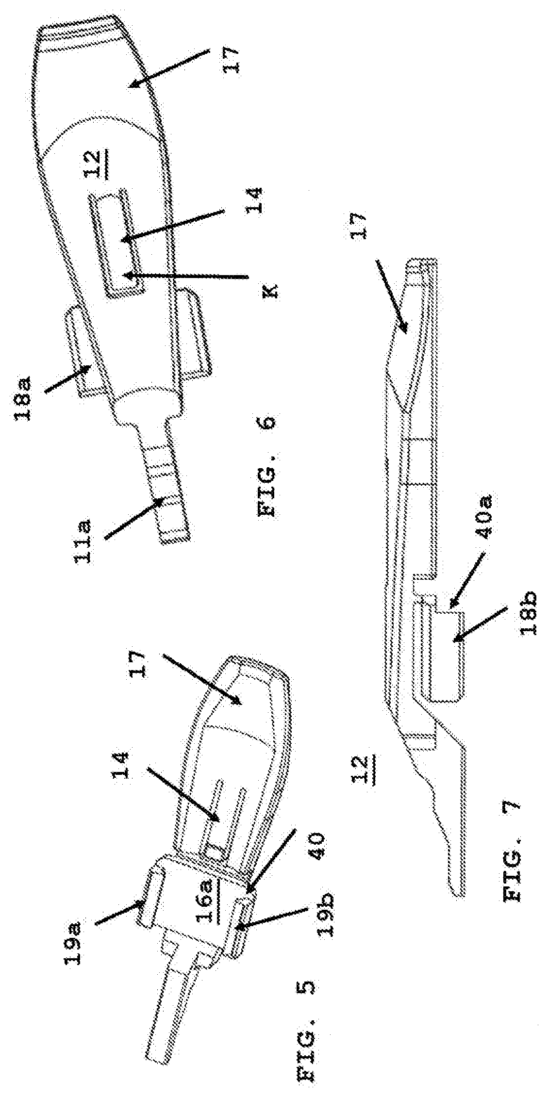
[0017] FIG. 5 is an underside view of the latch lever release;
[0018] FIG. 6 is a top view of the latch lever release;
[0019] FIG. 7 is a side view of the latch lever release;
[0020] FIG. 8 is front cross-section view of the fiber optic connector assembled with the latch lever release;
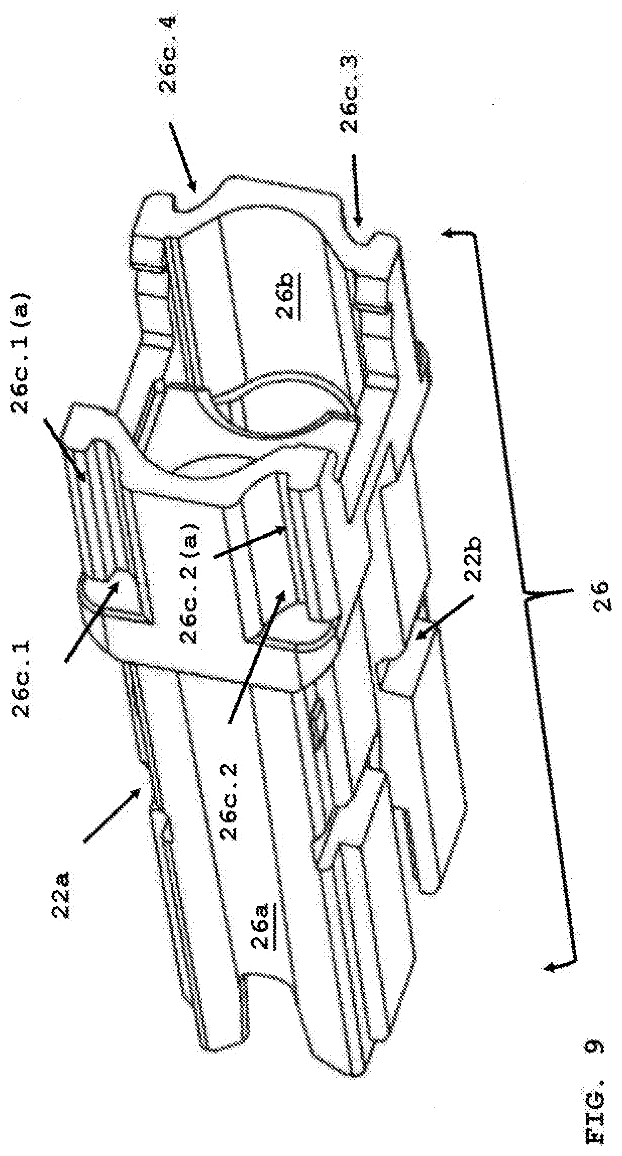
[0021] FIG. 9 is a perspective view of the connector housing;
[0022] FIG. 10 is a cross-section view of inserting the connector into a port;
[0023] FIG. 11 is a cross-section view of the connector fully inserted into the port;
[0024] FIG. 12 is a cross-section view of removing the connector from the port;
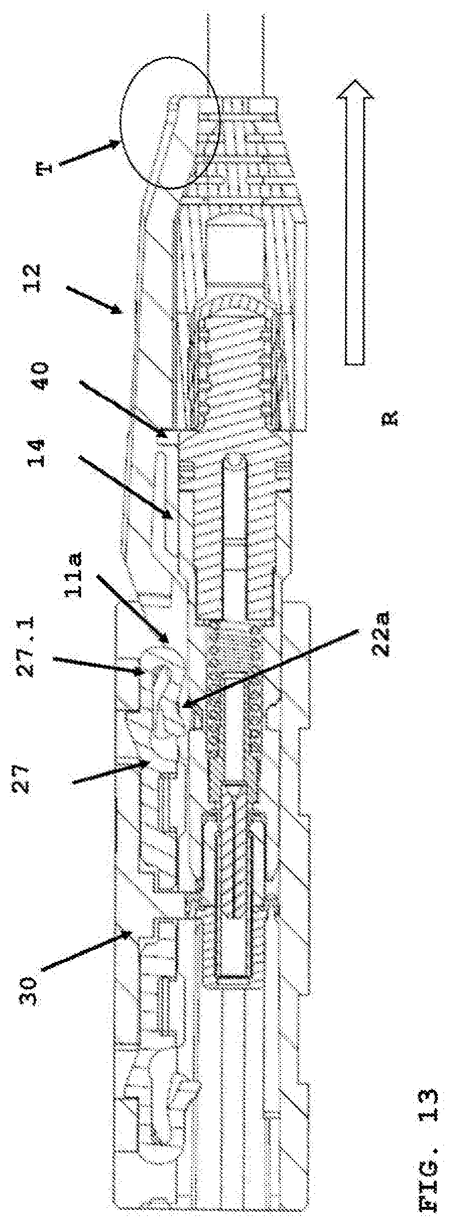
[0025] FIG. 13 is a cross-section view of the engagement device displaced from the connector housing releasing the connector from the port for removal;
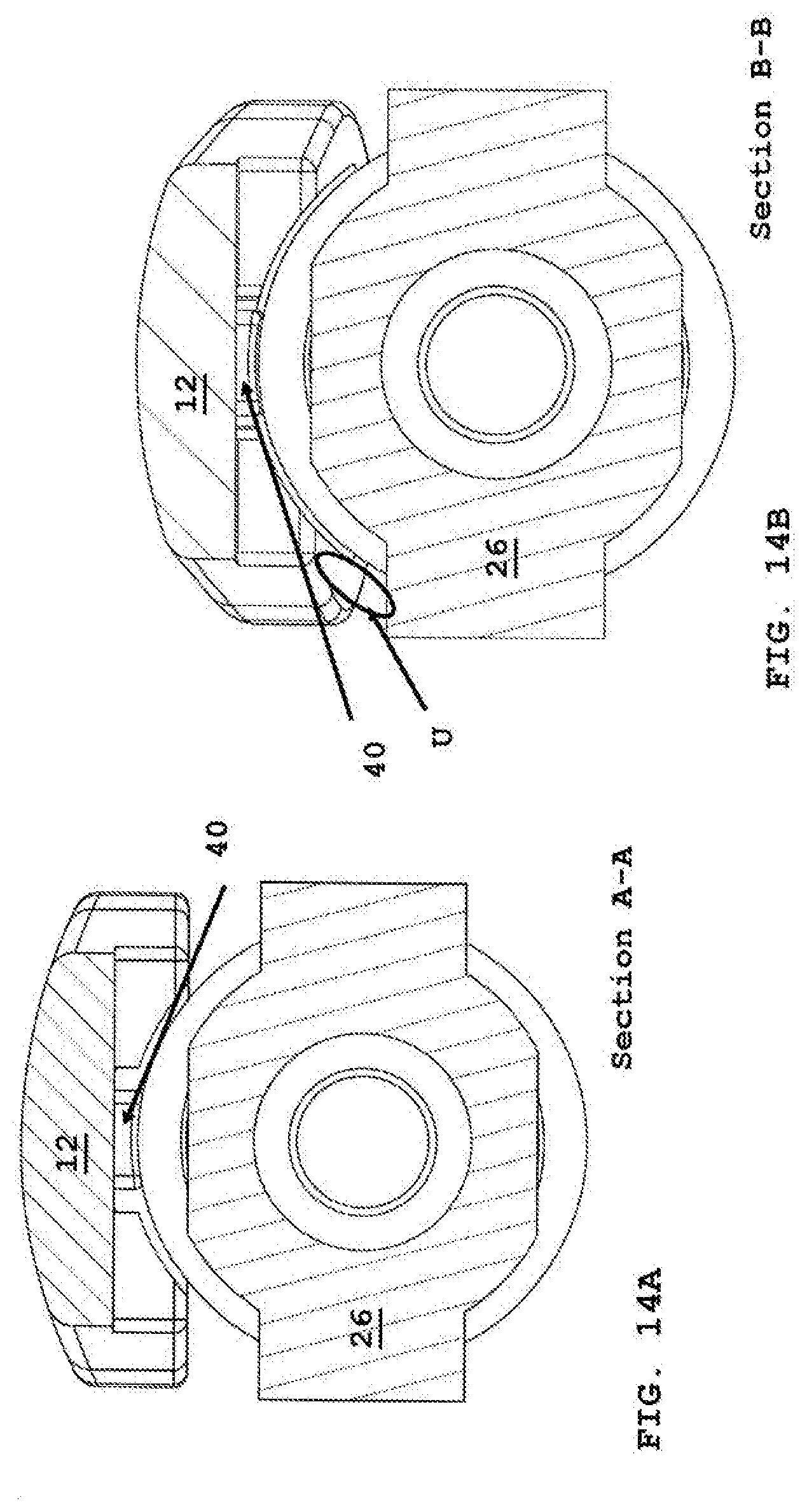
[0026] FIG. 14A is a front section view of the pivot point formed as part of the connector housing along section A-A of FIG. 10, and
[0027] FIG. 14B us a front section view of the pivot point formed as part of the connector housing along section B-B of FIG. 12.
[0028] Corresponding reference numbers indicate corresponding parts throughout the figures.
DETAILED DESCRIPTION
[0029] As used herein, the term "optical fiber" is intended to apply to all types of single mode and multi-mode light waveguides, including one or more bare optical fibers, coated optical fibers, loose-tube optical fibers, tight-buffered optical fibers, ribbonized optical fibers, bend performance optical fibers, bend insensitive optical fibers, nanostructured optical fibers or any other expedient for transmitting light signals. The term optical fiber cable may further include multi-fiber optic cables having a plurality of the optical fibers.
[0030] A "fiber optic cable" or an "optical cable" refers to a cable containing one or more optical fibers for conducting optical signals in beams of light. The optical fibers can be constructed from any suitable transparent material, including glass, fiberglass, and plastic. The cable can include a jacket or sheathing material surrounding the optical fibers. In addition, the cable can be connected to a connector on one end or on both ends of the cable.
[0031] For connection of cables together or with other fiber optic devices, the terminal ends of a cable may include a connector. A "connector," as used herein, refers to a device and/or components thereof that connects a first module or cable to a second module or cable. The connector may be configured for fiber optic transmission or electrical signal transmission. The connector may be any suitable type now known or later developed, such as, for example, a ferrule connector (FC), a fiber distributed data interface (FDDI) connector, an LC connector, a mechanical transfer (MT) connector, a square connector (SC) connector, an SC duplex connector, a straight tip (ST) connector, or a behind-the-wall (BTW) connector. The connector may generally be defined by a connector housing body. In some embodiments, the housing body may incorporate any or all of the components described herein.
[0032] Easily removing data centers connectors without touching the fiber optic cable is important to avoid optical fiber breakage. A one-step release and reducing the overall connector dimensional size is a time saver and reduces data center space use over prior art connectors.
[0033] Various parts, components or configurations described with respect to anyone embodiment above may also be adapted to any others of the embodiments provided. This disclosure is not limited to the particular systems, devices and methods described, as these may vary. The terminology used in the description is for the purpose of describing the particular versions or embodiments only, and is not intended to limit the scope.
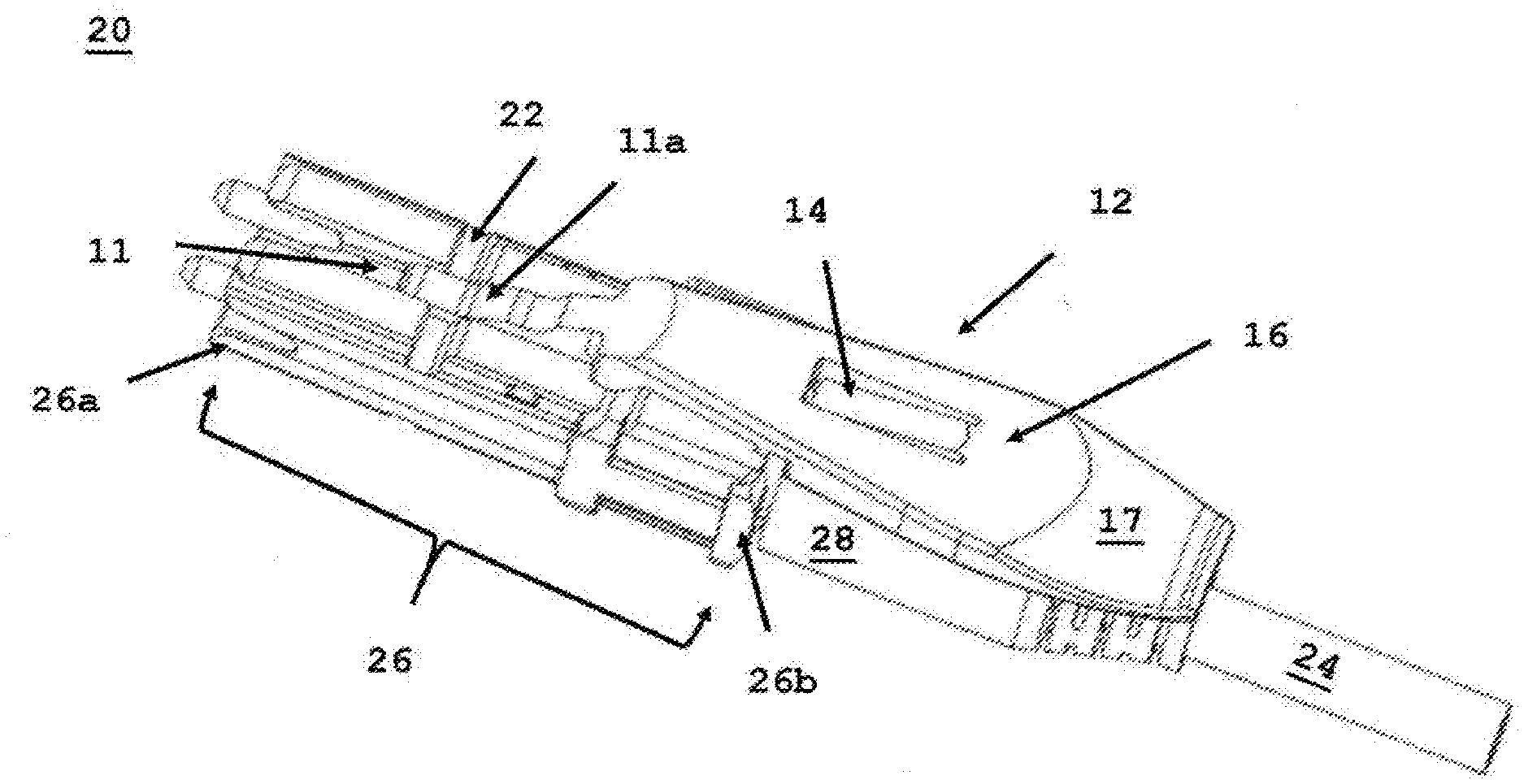
[0034] FIG. 1 depicts a fiber optic connector (20) assembled with latch lever release (12) on a first side of the housing (26). The latch lever release (12) is secured when opposing legs (18a, 18b) are positioned within opposing cut-outs (26c.1, 26c.2) formed as part of housing (26) (refer to FIG. 3). Housing (26) may be made up of front body (26a) and backbody (26b), A uni-body housing may be used with cut-outs, as described in FIG. 3, without departing from the scope of the present invention, as disclosed in U.S. Pat. Appl. US2018/0341069A1, Takano, "Adjustable Polarity Fiber Optic Connector Assemblies with Push-Pull Tabs", which is incorporated herein by reference. The housing (26) further comprises at least one optical ferrule (29) (refer to FIG. 2A) with at least one optical fiber therein provided by a fiber optic cable (24). A strain relief boot (28) is secured to a distal end of the housing. The boot (28) accepts the optical cable (24). The latch lever release (12) has a first end and a second end. The second end further comprises a trigger portion (17). The trigger portion (17) is slightly depressed to allow a user a tactile feel when depressing the trigger to remove the connector from a receptacle port as described below. A return member (14) maybe used to bias the latch lever release (12) to an original position after the user released a force applied distal of a pivot point (40) (refer to FIG. 12). As described below, a force "D" will release the connector from an engagement device within a receptacle port. The underside of main body (16) further comprises the pivot point (40) as described in FIG. 5 below. The first end of the latch lever release (12) comprises a ramp release surface (11a), that aids in displacing the engagement member (27) from the connector, so the connector can be removed from a receptacle port formed as part of an adapter (30a) (refer to FIG. 10). A channel (11) formed in the housing (26) is configured to accept the ramp release surface (11a). The channel (11) is perpendicular to a recess (22) that accepts the engagement device when the connector is fully inserted into an adapter port (30a). The recess (22) may be widthwise across the connector front body (26a) or a cut-out elsewhere on the connector outer housing configured to accept an engagement device within the adapter port (30a), such as a hook or an anchor device (27a) (refer to FIG. 10).
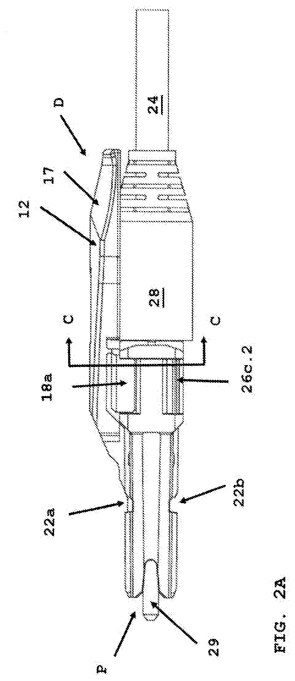
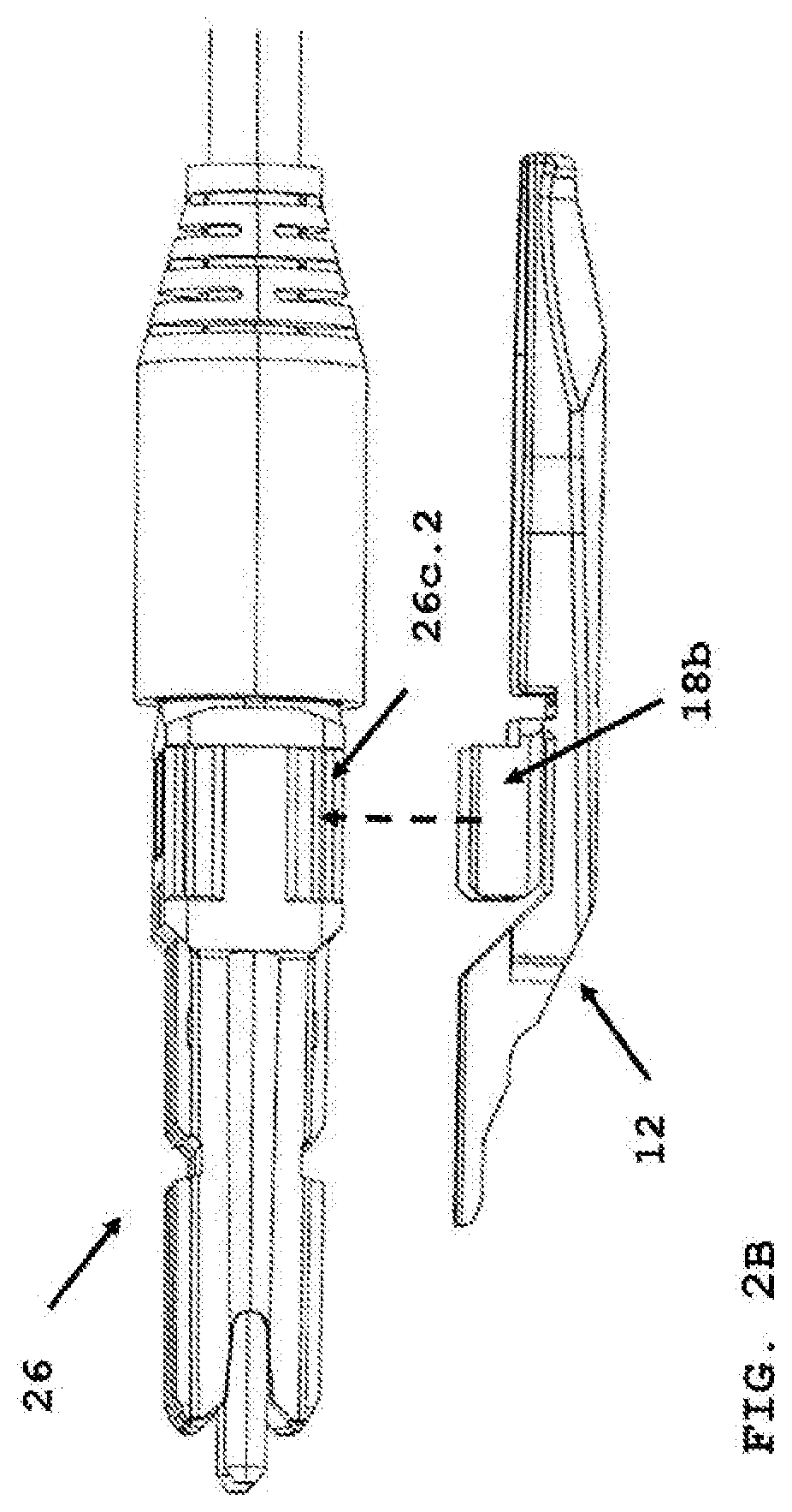
[0035] FIG. 2A depicts a side view of the connector (20) of FIG. 1. Ferrule (29) at the proximal end (P) of the connector (20) has at least one optical fiber provided by the optical cable (24). The cable (24) passes through the strain relief boot (28), at a distal end of the connector (D). Housing (26) has opposing recesses (22a, 22b) that allow the latch lever release (12) to be positioned on a first side of the housing within cut-outs (26c.1, 26c.4) (refer to FIG. 9). In FIG. 2A, the connector is a first polarity position, that is, when the connector is inserted into an adapter port (30a), the two ferrules (Tx (transmit, Rx (receive)) are in a first transmission configuration when opposing a second connector in an adapter (30) (refer to FIG. 10). As depicted in FIG. 2B, removing the latch lever release, and positioning on the second side of the housing, along dotted line, would secured the latch lever release (12) within cut-outs (26c.2, 26c.3) (refer to FIG. 9). The connector would be inserted into an adapter port in a second polarity or second transmission position, which rotated the connector 180 degrees.
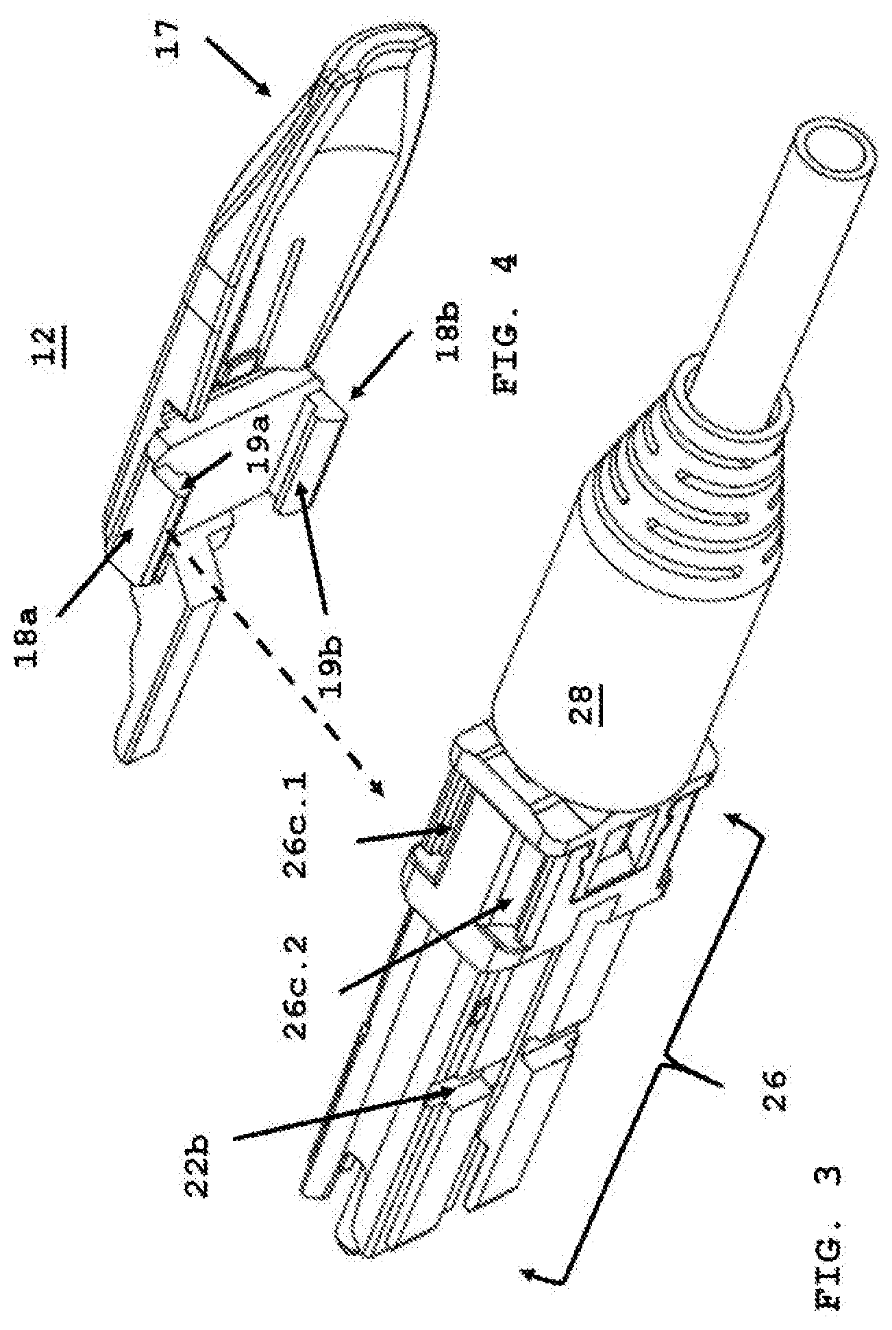
[0036] FIG. 3 depicts a perspective view of the connector housing (26) without the latch lever release (12) (refer to FIG. 4) secured by opposing legs (18a, 18b) with hooks (19a, 19b) within cut-outs (26c.1, 26c.4) for a first polarity position, as shown in FIG. 1. Hooks (19a, 19b) are received within corresponding, opposing cut-outs (26c.1 26c.4; 26c.2, 26c.3) formed in the housing, as shown in FIG. 9. FIG. 4 depicts latch lever release (12) prior to securing to housing (26) with opposing legs (18a, 18b) and hooks (19a, 19b). The legs are perpendicular to the main body (16). The hooks (19a, 19b) are at a distal end of each opposing leg. Nearer the second end of the latch lever release (12) is trigger portion (17) described above.
[0037] FIG. 5, FIG. 6 and FIG. 7 depicts views of the latch lever release (12). FIG. 5 is an underside view of the main body (16). Each leg (18a, 18b) has a hook (19a, 19b), as described above. FIG. 6 depicts a top view of latch lever release (12) further comprising return member (14). Return member (14) biases the latch lever release (12) to its original position when the user force "D" is released at the trigger portion (17). The return member is formed of a material with a spring constant (K) sufficient to bias the latch lever release to its original position. The material may be a plastic, spring or sheet metal. The return member maybe formed as part of the housing without departing from the scope of the present invention. Referring to FIG. 7, pivot point (40) is formed on the latch lever release (12) when there is gap or space (40a) between the hooks of each leg (18a, 18b) and the underside (16a) of the main body (16). So when the trigger portion (17) is depressed "D" (refer to FIG. 12), and there is no pivot point (40) formed as part of the housing (26) (refer to FIG. 10), the legs are lifted slightly and contacts a surface underneath chamfered edge (26c.1(a)) of cut-out (26a.1) (refer to FIG. 9), and this contact acts as the pivot point allowing the first end ramp release surface (11a) (refer to FIG. 6) to rotate up, as described below in FIG. 10 to FIG. 12, that allows the ramp release surface to displace the engagement device securing the connector within a port (30a).
[0038] FIG. 8 is a cross-section view along line C-C of FIG. 2A. Opposing legs (18a, 18b) am secured with cut-outs (26c.1, 26c.4). Hooks (19a, 19b) have engaged a corresponding chamfered edge (26c.1(a)-26c.4(a)) establishing the pivot point (40). FIG. 9 depicts housing (26) with a front body (26a) and backbody (26b). Cut-outs (26c.1-26c.4) are formed as part of the backbody (26b). The housing may be unibody as described above with the cut-outs formed as part of the unibody connector housing. Each cut-out has an opening or recess that accepts a leg hook (19a, 19b). Each cut-out has a chamfered edge (26c.1(a)-26c.4(a)). The chamfered edges act as a pivot point as described above. The chamfered edges also allow the latch lever release to be removed from a first side of the housing and secured to a second side of the housing without binding or jamming during polarity changes as described in FIG. 2A and FIG. 2B. Opposing recesses (22a, 22b) accept the engagement device when inserted into a port in first polarity or second polarity configuration.
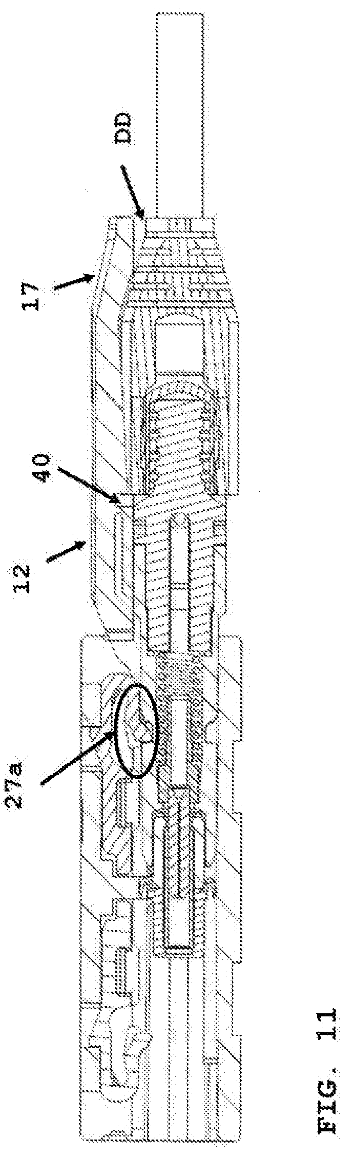
[0039] FIG. 10 depicts inserting connector (20) within port (30a) of the adapter (30). Engagement device (27) is being lifted by ramp release surface (11a), and once the connector is fully inserted, as shown in FIG. 11, the anchor device (27a) is secured with the recess (22a, 22b) depending on the polarity configuration of the connector. FIG. 10 further shows pivot point (40) is formed as part of the housing (26). When the latch release lever (12) is secured about the housing, and fully inserted, there is a distance "DD", that a distal end of the lever is above the strain relief boot (28). When the user depresses near trigger portion (17) or distal of the pivot point (40), where distal end is nearer the incoming optical cable, the first end of the latch lever release will rotate up as depicted in FIG. 12.
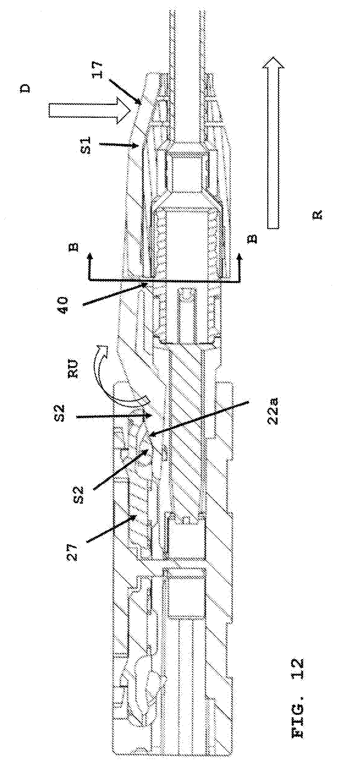
[0040] FIG. 12 depicts a force "D" being applied near the trigger portion (17) as step 1 (S1) of removing the connector from the port. The first end of the latch lever release (12) rotates up in direction of "RU", and the ramp release surface displaces the engagement device (27) from the recess (22a, 22b). As the connector is being removed in the direction of arrow (R), the engagement device is displaced from the recess. The first end of the latch lever release (12) is rotating up about the pivot point (40) at step 2 (S2) as depicted in FIG. 12. FIG. 13 depicts the trigger portion fully depressed at call out (T), just prior to removing the connector in the direction of "R". In FIG. 13, a middle arm (27.1) of the anchor device (27) is positioned against release ramp surface (11a) and within recess (22a).
[0041] FIG. 14A depicts a cross-section along A-A of FIG. 10 when the connector is fully inserted into the port, and prior to depressing the latch lever release (12) near trigger portion (17) or distal of the pivot point (40). FIG. 14B depicts a cross-section along B-B of FIG. 12. The latch lever release (12) is deflected slight upward, at "U", as the lever rotates about pivot point (40).
[0042] In the above detailed description, reference is made to the accompanying drawings, which form a part hereof. In the drawings, similar symbols typically identify similar components, unless context dictates otherwise. The illustrative embodiments described in the detailed description, drawings, and claims are not meant to be limiting. Other embodiments may be used, and other changes may be made, without departing from the spirit or scope of the subject matter presented herein. It will be readily understood that the aspects of the present disclosure, as generally described herein, and illustrated in the figures, can be arranged, substituted, combined, separated, and designed in a wide variety of different configurations, all of which are explicitly contemplated herein.
[0043] As used in this document, the singular forms "a," "an," and "the" include plural references unless the context clearly dictates otherwise. Unless defined otherwise, all technical and scientific terms used herein have the same meanings as commonly understood by one of ordinary skill in the art. Nothing in this disclosure is to be construed as an admission that the embodiments described in this disclosure are not entitled to antedate such disclosure by virtue of prior invention. As used in this document, the term "comprising" means "including, but not limited to."
[0044] While various compositions, methods, and devices are described in terms of "comprising" various components or steps (interpreted as meaning "including, but not limited to"), the compositions, methods, and devices can also "consist essentially of" or "consist of" the various components and steps, and such terminology should be interpreted as defining essentially closed-member groups.
[0045] With respect to the use of substantially any plural and/or singular terms herein, those having skill in the art can translate from the plural to the singular and/or from the singular to the plural as is appropriate to the context and/or application. The various singular/plural permutations may be expressly set forth herein for sake of clarity.
[0046] It will be understood by those within the art that, in general, terms used herein, and especially in the appended claims (e.g., bodies of the appended claims) are generally intended as "open" terms (e.g., the term "including" should be interpreted as "including but not limited to," the term "having" should be interpreted as "having at least," the term "includes" should be interpreted as "includes but is not limited to," etc.). It will be further understood by those within the art that if a specific number of an introduced claim recitation is intended, such an intent will be explicitly recited in the claim, and in the absence of such recitation no such intent is present. For example, as an aid to understanding, the following appended claims may contain usage of the introductory phrases "at least one" and "one or more" to introduce claim recitations. However, the use of such phrases should not be construed to imply that the introduction of a claim recitation by the indefinite articles "a" or "an" limits any particular claim containing such introduced claim recitation to embodiments containing only one such recitation, even when the same claim includes the introductory phrases "one or more" or "at least one" and indefinite articles such as "a" or "an" (e.g., "a" and/or "an" should be interpreted to mean "at least one" or "one or more"); the same holds true for the use of definite articles used to introduce claim recitations. In addition, even if a specific number of an introduced claim recitation is explicitly recited, those skilled in the art will recognize that such recitation should be interpreted to mean at least the recited number (e.g., the bare recitation of "two recitations," without other modifiers, means at least two recitations, or two or more recitations). Furthermore, in those instances where a convention analogous to "at least one of A, B, and C, etc." is used, in general such a construction is intended in the sense one having skill in the art would understand the convention (e.g., "a system having at least one of A, B, and C" would include but not be limited to systems that have A alone, B alone, C alone, A and B together, A and C together, B and C together, and/or A, B, and C together, etc.). Various of the above-disclosed and other features and functions, or alternatives thereof, may be combined into many other different systems or applications. Variations or improvements therein may be subsequently made by those skilled in the art, each of which is also intended to be encompassed by the disclosed embodiments.
* * * * *
D00000
D00001
D00002
D00003
D00004
D00005
D00006
D00007
D00008
D00009
D00010
D00011
D00012
XML
uspto.report is an independent third-party trademark research tool that is not affiliated, endorsed, or sponsored by the United States Patent and Trademark Office (USPTO) or any other governmental organization. The information provided by uspto.report is based on publicly available data at the time of writing and is intended for informational purposes only.
While we strive to provide accurate and up-to-date information, we do not guarantee the accuracy, completeness, reliability, or suitability of the information displayed on this site. The use of this site is at your own risk. Any reliance you place on such information is therefore strictly at your own risk.
All official trademark data, including owner information, should be verified by visiting the official USPTO website at www.uspto.gov. This site is not intended to replace professional legal advice and should not be used as a substitute for consulting with a legal professional who is knowledgeable about trademark law.