Method For Determining A Volumetric And/or Mass Flow Rate
Reith; Patrick ; et al.
U.S. patent application number 16/955165 was filed with the patent office on 2020-12-17 for method for determining a volumetric and/or mass flow rate. The applicant listed for this patent is TrueDyne Sensors AG. Invention is credited to Christof Huber, Patrick Reith.
| Application Number | 20200393279 16/955165 |
| Document ID | / |
| Family ID | 1000005060474 |
| Filed Date | 2020-12-17 |


| United States Patent Application | 20200393279 |
| Kind Code | A1 |
| Reith; Patrick ; et al. | December 17, 2020 |
METHOD FOR DETERMINING A VOLUMETRIC AND/OR MASS FLOW RATE
Abstract
The invention relates to a method for determining a volumetric and/or mass flow rate of a medium (M) flowing in a tube (20), wherein a density and/or a viscosity of the fluid (F) is/are determined by means of a MEMS sensor chip (30), wherein the medium (M) flowing in the tube (20) at least partially flows through a measuring channel (31) of the MEMS sensor chip (30) to determine the density and/or the viscosity of the fluid (F), and wherein the volumetric and/or mass flow rate of the medium (M) is determined regardless of the medium by means of a detected pressure drop (|p2-p1|) over the measuring channel (31) of the MEMS sensor chip (30) and the density and/or viscosity determined by the MEMS sensor (30).
| Inventors: | Reith; Patrick; (Basel, CH) ; Huber; Christof; (Bern, CH) | ||||||||||
| Applicant: |
|
||||||||||
|---|---|---|---|---|---|---|---|---|---|---|---|
| Family ID: | 1000005060474 | ||||||||||
| Appl. No.: | 16/955165 | ||||||||||
| Filed: | November 15, 2018 | ||||||||||
| PCT Filed: | November 15, 2018 | ||||||||||
| PCT NO: | PCT/EP2018/081426 | ||||||||||
| 371 Date: | June 18, 2020 |
| Current U.S. Class: | 1/1 |
| Current CPC Class: | G01F 1/88 20130101; G01N 9/002 20130101; G01F 1/50 20130101; G01N 11/16 20130101; G01F 5/005 20130101; G01F 1/363 20130101 |
| International Class: | G01F 1/88 20060101 G01F001/88; G01F 1/36 20060101 G01F001/36; G01F 1/50 20060101 G01F001/50; G01F 5/00 20060101 G01F005/00; G01N 9/00 20060101 G01N009/00; G01N 11/16 20060101 G01N011/16 |
Foreign Application Data
| Date | Code | Application Number |
|---|---|---|
| Dec 20, 2017 | DE | 10 2017 130 781.8 |
Claims
1. A method for determining a volumetric and/or mass flow rate of a medium (M) flowing in a tube (20), wherein a density and/or a viscosity of the fluid (F) is/are determined by means of a MEMS sensor chip (30), wherein the medium (M) flowing in the tube (20) at least partially flows through a measuring channel (31) of the MEMS sensor chip (30) to determine the density and/or the viscosity of the fluid (F), and wherein the volumetric and/or mass flow rate of the medium (M) is determined regardless of the medium by means of a detected pressure drop (|p2-p1|) over the measuring channel (31) of the MEMS sensor chip (30) and the density and/or viscosity determined by the MEMS sensor (30).
2. The method according to claim 1, wherein the measuring channel (31) of the MEMS sensor chip (30) is connected to the tube (20) in such a way that the medium (M) flows completely through the measuring channel (31) of the MEMS sensor (30) so that the pressure drop (|p2-p1|) is generated substantially by the measuring channel (31) of the MEMS sensor chip (30).
3. The method according to claim 1, wherein an orifice plate (21) is introduced into the tube in such a way that the medium flows through the orifice plate and the measuring channel of the MEMS sensor chip in parallel and the pressure drop (|p2-p1|) is generated by the orifice plate (21) introduced into the tube (20) and the measuring channel (31) of the MEMS sensor chip (30) through which the medium partially flows.
4. The method according to the preceding claim, wherein the orifice plate (21) and the measuring channel (31) are matched to one another in such a way that a flow ratio of the medium (M) flowing through the measuring channel (31) to the medium (M) flowing through the orifice plate (21) is set to be less than 1:20, preferably less than 1:100, especially preferably less than 1:500.
5. A device for determining a volumetric and/or mass flow rate (1) of a medium (M) flowing in a tube (20), comprising at least: A MEMS sensor chip (30) having a measuring channel (31) which is connected to the tube (20) to determine a density and/or a viscosity of the medium (M) in such a way that the medium (M) flows at least partially through the measuring channel (31), A differential pressure measuring arrangement (40) for detecting a pressure drop (|p2-p1|) over the measuring channel (31) of the MEMS sensor chip (30), and An evaluation unit (50) which is set up to determine the volumetric and/or mass flow rate of the medium (M) regardless of the medium on the basis of the pressure drop (|p2-p1|) determined by the differential pressure measuring arrangement and the density and/or viscosity determined by the MEMS sensor chip (30).
6. The device according to the preceding claim, wherein the MEMS sensor chip (30) is connected to the tube (20) in such a way that the medium (M) flows completely through the measuring channel (31) of the MEMS sensor chip (30) so that substantially the measuring channel (31) of the MEMS sensor chip (30) generates the pressure drop (|p2-p1|) and the differential pressure measuring arrangement (40) is further designed to detect the pressure drop over the measuring channel (31) of the MEMS sensor chip (30).
7. The device according to claim 5, further comprising an orifice plate (21) through which the medium (M) flows, wherein the orifice plate (21) and the measuring channel (31) of the MEMS sensor chip (30) are introduced into the tube (20) in such a way that the medium (M) flows through both the orifice plate (21) and the measuring channel (31), preferably in parallel.
8. The device according to at least one of claims 5-7, wherein the measuring channel (31) of the MEMS sensor chip (30) has a flow cross-section (A.sub.measuring channel) with a diameter in the range of 0.03-1 mm, preferably 0.05-0.6 mm, especially preferably 0.1-0.3 mm.
9. The device according to at least one of claims 5-8, wherein the orifice plate (21) has an orifice plate opening with a flow cross-section (A.sub.aperture plate), wherein the flow cross-section (A.sub.aperture plate) of the orifice plate opening is designed in such a way that a flow ratio of the medium (M) flowing through the flow cross-section (A.sub.measuring channel) of the measuring channel (31) to the medium (M) flowing through the flow cross-section (A.sub.aperture plate) of the orifice plate opening (A.sub.aperture plate) is set to be less than 1:20, preferably 1:100, especially preferably less than 1:500.
Description
[0001] The invention relates to a method for determining a volumetric and/or mass flow rate of a medium flowing in a tube, and to a device for determining a volumetric and/or mass flow rate of a medium flowing in a tube.
[0002] Devices for determining a volumetric flow rate according to the differential pressure principle are known per se. Here, orifice plates, for example, are used as effective pressure setting devices and a pressure difference across the orifice plate is detected. A differential pressure measuring device and knowledge of the material's characteristic values, especially viscosity, density and isentropic exponent, are required for the measurement itself. Details for this are defined in the standard ISO 5167-1 from the year 2004 and 2:2003 from the year 2003.
[0003] A disadvantage of this is that the measurement of the volumetric flow rate is dependent on the material values of the medium (media-dependent), which must therefore be known.
[0004] It is therefore an object of the present invention to remedy this.
[0005] The object is achieved according to the invention by the method according to claim 1 and the device according to claim 5.
[0006] In order to determine a volumetric and/or mass flow rate of a medium flowing in a tube, the method according to the invention provides that a density and/or a viscosity of the fluid is/are determined by means of a MEMS sensor chip, wherein the medium flowing in the tube at least partially flows through a measuring channel of the MEMS sensor chip to determine the density and/or the viscosity of the fluid, and wherein the volumetric and/or mass flow rate of the medium is determined regardless of the medium by means of a detected pressure drop |p2-p1| over the measuring channel of the MEMS sensor chip and the density and/or viscosity determined by the MEMS sensor.
[0007] MEMS sensor chips are micro-electromechanical systems which are used in metrology for metrologically detecting one or more measurement values. These MEMS sensor chips are regularly produced using methods customary in semiconductor technology, such as etching processes, oxidation methods, implantation methods, bonding methods and/or coating methods, using single- or multi-layer wafers, especially silicon-based wafers.
[0008] MEMS sensor chips which are used to determine a measurement value of a flowing medium, especially a liquid or a gas, usually have at least one measuring channel, the interior of which forms a line through which the medium flows during measuring.
[0009] According to the invention, it is now proposed that, in parallel with the conventional volumetric flow rate measurement according to the differential pressure principle, a MEMS sensor chip is determined the current density and/or viscosity of the medium so that a medium-independent volumetric and/or mass flow rate measurement is made possible.
[0010] A further development of the invention provides that the measuring channel of the MEMS sensor chip is connected to the tube in such a way that the medium flows completely through the measuring channel of the MEMS sensor chip, so that the pressure drop |p2-p1| is substantially generated by the measuring channel of the MEMS sensor chip.
[0011] An alternative further development of the invention provides that an orifice plate is introduced into the tube in such a way that the medium flows through the orifice plate and the measuring channel of the MEMS sensor chip in parallel and the pressure drop |p2-p1| is generated by the orifice plate introduced into the tube and the measuring channel of the MEMS sensor chip through which medium partially flows. The further development can especially provide that the orifice plate and the measuring channel are matched to one another in such a way that a flow ratio of the medium flowing through the measuring channel to the medium flowing through the orifice plate is set to be less than 1:20, preferably 1:100, especially preferably less than 1:500.
[0012] The device according to the invention for determining a volumetric and/or mass flow rate of a medium flowing in a tube comprises at least: [0013] A MEMS sensor chip having a measuring channel which is connected to the tube to determine a density and/or a viscosity of the medium in such a way that the medium flows at least partially through the measuring channel, [0014] A differential pressure measuring arrangement for detecting a pressure drop |p2-p1| over the measuring channel of the MEMS sensor chip, and [0015] An evaluation unit which is set up to determine the volumetric and/or mass flow rate of the medium regardless of the medium on the basis of the pressure drop |p2-p1| determined by the differential pressure measuring arrangement and the density and/or viscosity determined by the MEMS sensor chip.
[0016] A further development of the invention provides that the MEMS sensor chip is connected to the tube in such a way that the medium flows completely through the measuring channel of the MEMS sensor chip, so that substantially the measuring channel of the MEMS sensor chip generates the pressure drop |p2-p1| and the differential pressure measuring arrangement is further designed to detect the pressure drop over the measuring channel of the MEMS sensor chip.
[0017] An alternative further development of the invention provides for this purpose that the device further has an orifice plate through which the medium flows, wherein the orifice plate and the measuring channel of the MEMS sensor chip are introduced into the tube in such a way that the medium flows through both the orifice plate and the measuring channel, preferably in parallel.
[0018] A further development of the invention provides that the measuring channel of the M EMS sensor chip has a flow cross-section A.sub.measuring channel with a diameter in the range of 0.03-1 mm, preferably 0.05-0.6 mm, especially preferably 0.1-0.3 mm.
[0019] Another further development of the invention provides that the orifice plate has an orifice plate opening with a flow cross-section A.sub.aperture plate, wherein the flow cross-section A.sub.aperture plate of the orifice plate opening is designed in such a way that a flow ratio of the medium flowing through the flow cross-section A.sub.measuring channel of the measuring channel to the medium flowing through the flow cross-section A.sub.aperture plate of the orifice plate opening A.sub.aperture plate is set to be less than 1:20, preferably less than 1:100, especially preferably less than 1:500.
[0020] The invention is explained in more detail with reference to the following drawings. The figures show:
[0021] FIG. 1: a first exemplary embodiment of the invention, and
[0022] FIG. 2: a second exemplary embodiment of the invention alternative to the first embodiment.
[0023] FIG. 1 shows a first exemplary embodiment of the invention. In this case, the device for determining a volumetric and/or mass flow rate 1 comprises a differential pressure measuring arrangement 40 for determining a volumetric flow rate which is constructed according to the effective pressure setting device principle and has an orifice plate 21 in a tube 20 through which a medium M is to flow. The tube 20 typically has a flow cross-section A.sub.tube with a diameter in the range of <30 mm, preferably <10 mm, especially preferably <5 mm. The orifice plate 21 is introduced into the tube 20 in the flow direction as an effective pressure setting device. The orifice plate 21 has an orifice plate opening with an opening or flow cross-section A.sub.aperture plate with a diameter of typically 0.2-10 mm, preferably 0.4-5 mm, especially preferably 0.7-2 mm. In addition to the flow path of the medium M through the orifice plate 21, in a flow path parallel thereto, a MEMS sensor chip 30 for determining the density and/or viscosity of the medium M is connected to the tube 20. The MEMS sensor chip 30 has a measuring channel 31 through which the medium M flows during measuring so that the density and/or viscosity of the medium M can be determined by the M EMS sensor chip 30. The measuring channel 31 typically has a flow cross-section A.sub.measuring channel with a diameter in the range of 0.03-1 mm, preferably 0.05-0.6 mm, especially preferably 0.1-0.3 mm.
[0024] In principle, MEMS sensor chip 30 operates with an oscillatable unit whose oscillation behavior is detected in order to determine the density and/or the viscosity. In this case, the viscosity, for example, of the medium M can be determined using a Q factor of the oscillation of the oscillatable unit. Depending on the medium M, the oscillatable unit of the MEMS sensor chip 30 can be designed differently. In the case where the medium M comprises a gas, the oscillatable unit can be designed, for example, in the form of a cantilever or a crystal oscillator, whereas in the case where the medium M comprises a liquid, the oscillatable unit can be designed, for example, in the form of a measuring channel 31 excited to oscillation. In both cases, the fact that at least one property of the oscillation of the oscillatable unit changes due to a density and/or viscosity of the medium M so that the density and/or viscosity can be determined is utilized.
[0025] The device for determining a volumetric and/or mass flow rate 1 further comprises an evaluation unit 50 which is set up to determine the volumetric and/or mass flow rate of the medium regardless of the medium on the basis of the pressure drop |p2-p1| determined by the differential pressure measuring arrangement 40 and the density and/or viscosity determined by the MEMS sensor chip 30. For this purpose, the evaluation unit 50 can determine the volumetric flow rate through the tube on the basis of the determined pressure drop |p2-p1| and the viscosity according to the Hagen-Poiseuille law. Furthermore, the evaluation unit 50 can also determine the mass flow rate through the tube 20 on the basis of the determined density.
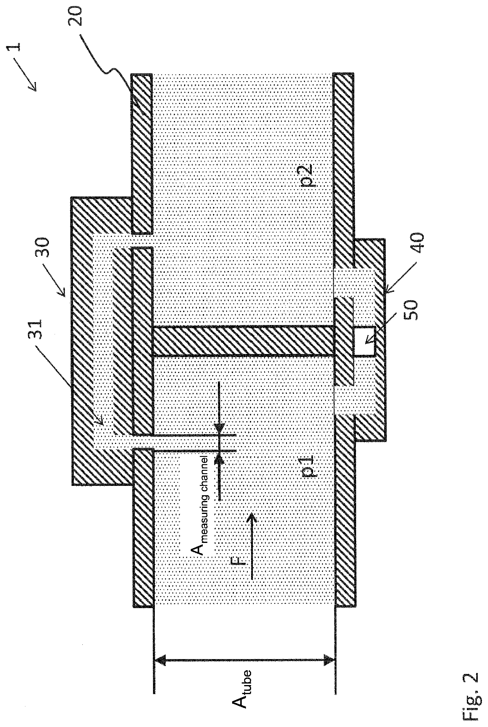
[0026] FIG. 2 shows a second exemplary embodiment of the invention that is an alternative to the first exemplary embodiment. The device for determining a volumetric and/or mass flow rate 1 differs from the first exemplary embodiment in that, although a differential pressure measuring arrangement 40 is also provided here, it has no orifice plate in this case, but is designed in such a way that the medium M flows completely through the measuring channel 31 of the MEMS sensor chip 30. This means that the differential pressure measuring arrangement 40 is thus designed in such a way that only a first pressure p1 before the measuring channel of the MEMS sensor chip and a second pressure p2 after the measuring channel of the MEMS sensor chip are detected to determine the pressure drop |p2-p1|.
REFERENCE SYMBOLS
[0027] 1 Device for determining a volumetric and/or mass flow rate [0028] 20 Tube [0029] 21 Orifice plate [0030] 30 MEMS sensor chip for determining the density and/or viscosity [0031] 31 Measuring channel of the MEMS sensor [0032] 40 Device for determining a pressure drop [0033] 50 Evaluation unit [0034] A.sub.aperture plate Flow cross-section of orifice plate opening [0035] A.sub.measuring channel Flow cross-section of measuring channel [0036] A.sub.tube Flow cross-section of tube [0037] |p2-p1| Amount of pressure drop [0038] M Medium
* * * * *
D00000
D00001
D00002
XML
uspto.report is an independent third-party trademark research tool that is not affiliated, endorsed, or sponsored by the United States Patent and Trademark Office (USPTO) or any other governmental organization. The information provided by uspto.report is based on publicly available data at the time of writing and is intended for informational purposes only.
While we strive to provide accurate and up-to-date information, we do not guarantee the accuracy, completeness, reliability, or suitability of the information displayed on this site. The use of this site is at your own risk. Any reliance you place on such information is therefore strictly at your own risk.
All official trademark data, including owner information, should be verified by visiting the official USPTO website at www.uspto.gov. This site is not intended to replace professional legal advice and should not be used as a substitute for consulting with a legal professional who is knowledgeable about trademark law.