Fire Pit Systems
Johnston; Todd
U.S. patent application number 16/437384 was filed with the patent office on 2020-12-17 for fire pit systems. The applicant listed for this patent is Merkur Holdings Limited. Invention is credited to Todd Johnston.
| Application Number | 20200393136 16/437384 |
| Document ID | / |
| Family ID | 1000004143120 |
| Filed Date | 2020-12-17 |


| United States Patent Application | 20200393136 |
| Kind Code | A1 |
| Johnston; Todd | December 17, 2020 |
FIRE PIT SYSTEMS
Abstract
A representative fire pit system incorporates: a base having an upper surface and defining an outer perimeter; a housing defining an interior, a bottom opening and a top opening, the bottom opening communicating with the interior and the top opening communicating with the interior, the housing having legs spaced from each other, the legs being attached to the base and configured such that the bottom opening is displaced from the upper surface of the base and the housing extends upwardly from the upper surface; a fire platform disposed within the interior of the housing between the bottom opening and the top opening, the fire platform extending across the interior and being configured to support combustible materials placed thereon, the fire platform defining openings therethrough; and support legs extending downwardly from the base, the support legs being configured to raise the base from surface upon which the base is positioned.
| Inventors: | Johnston; Todd; (Fairburn, GA) | ||||||||||
| Applicant: |
|
||||||||||
|---|---|---|---|---|---|---|---|---|---|---|---|
| Family ID: | 1000004143120 | ||||||||||
| Appl. No.: | 16/437384 | ||||||||||
| Filed: | June 11, 2019 |
| Current U.S. Class: | 1/1 |
| Current CPC Class: | F24B 1/198 20130101; F24B 1/181 20130101; F24C 1/16 20130101 |
| International Class: | F24C 1/16 20060101 F24C001/16; F24B 1/181 20060101 F24B001/181; F24B 1/198 20060101 F24B001/198 |
Claims
1. A fire pit system comprising: a base having an upper surface and defining an outer perimeter; a housing defining an interior, a bottom opening and a top opening, the bottom opening communicating with the interior and the top opening communicating with the interior, the housing having legs spaced from each other, the legs being attached to the base and configured such that the bottom opening is displaced from the upper surface of the base and the housing extends upwardly from the upper surface; a fire platform disposed within the interior of the housing between the bottom opening and the top opening, the fire platform extending across the interior and being configured to support combustible materials placed thereon, the fire platform defining openings therethrough; and support legs extending downwardly from the base, the support legs being configured to raise the base from surface upon which the base is positioned.
2. A system as defined in claim 1, wherein the housing exhibits a rectangular cross-section.
3. A system as defined in claim 2, wherein the housing is formed of four interconnected panels.
4. A system as defined in claim 3, wherein the first of the panels defines a carry opening disposed between the top and the fire platform.
5. A system as defined in claim 3, wherein: a first of the panels has a body portion, a first flange, a second flange, a first leg portion and a second leg portion; the body portion defines a first side edge and an opposing second side edge; the first flange extends outwardly from the body portion along the first side edge; and the second flange extends outwardly from the body portion along the second side edge.
6. A system as defined in claim 5, wherein: the first flange of the first of the panels defines a first slot; and a second of the panels has a pin configured to engage within the first slot to secure the second of the panels to the first of the panels.
7. A system as defined in claim 5, wherein: the first leg portion has a first side edge aligned with the first side edge of the body portion, and the first flange further extends along the first side edge of the first leg portion; and the second leg portion has a second side edge aligned with the second side edge of the body portion, and the second flange further extends along the second side edge of the second leg portion.
8. A system as defined in claim 7, wherein the first leg portion and the second leg portion define, at least in part, an air flow path between the housing and the base.
9. A system as defined in claim 7, wherein: the first leg portion defines a bottom edge and has a first mounting flange extending outwardly therefrom; the second leg portion defines a bottom edge and has a second mounting flange extending outwardly therefrom; and the first mounting flange and the second mounting flange are configured to mount the first of the panels to the base.
Description
BACKGROUND
Technical Field
[0001] The present disclosure relates to fire pits for burning combustible materials.
Description of the Related Art
[0002] Conventional fire pits are metal structures used for providing platforms, raised above ground level, upon which fires may be formed. Many of these structures are intended to be portable for convenience of use during camping, for example. Unfortunately, these fire pits tend to suffer from complicated disassembly/assembly procedures and/or other shortcomings, such as limited airflow paths for sustaining the fires. Therefore, it is desirable to provide fire pit systems that address these and/or other perceived deficiencies.
SUMMARY
[0003] Fire pit systems are provided. An embodiment of a fire pit system comprises: a base having an upper surface and defining an outer perimeter; a housing defining an interior, a bottom opening and a top opening, the bottom opening communicating with the interior and the top opening communicating with the interior, the housing having legs spaced from each other, the legs being attached to the base and configured such that the bottom opening is displaced from the upper surface of the base and the housing extends upwardly from the upper surface; a fire platform disposed within the interior of the housing between the bottom opening and the top opening, the fire platform extending across the interior and being configured to support combustible materials placed thereon, the fire platform defining openings therethrough; and support legs extending downwardly from the base, the support legs being configured to raise the base from surface upon which the base is positioned.
[0004] In some embodiments, the housing exhibits a rectangular cross-section.
[0005] In some embodiments, the housing is formed of four interconnected panels.
[0006] In some embodiments, the first of the panels defines a carry opening disposed between the top and the fire platform.
[0007] In some embodiments, a first of the panels has a body portion, a first flange, a second flange, a first leg portion and a second leg portion; the body portion defines a first side edge and an opposing second side edge; the first flange extends outwardly from the body portion along the first side edge; and the second flange extends outwardly from the body portion along the second side edge.
[0008] In some embodiments, the first flange of the first of the panels defines a first slot; and a second of the panels has a pin configured to engage within the first slot to secure the second of the panels to the first of the panels.
[0009] In some embodiments, the first leg portion has a first side edge aligned with the first side edge of the body portion, and the first flange further extends along the first side edge of the first leg portion; and the second leg portion has a second side edge aligned with the second side edge of the body portion, and the second flange further extends along the second side edge of the second leg portion.
[0010] In some embodiments, the first leg portion and the second leg portion define, at least in part, an air flow path between the housing and the base.
[0011] In some embodiments, the first leg portion defines a bottom edge and has a first mounting flange extending outwardly therefrom; the second leg portion defines a bottom edge and has a second mounting flange extending outwardly therefrom; and the first mounting flange and the second mounting flange are configured to mount the first of the panels to the base.
[0012] Other features and/or advantages will become apparent from the following detailed description of the preferred but non-limiting embodiments.
BRIEF DESCRIPTION OF THE DRAWINGS
[0013] FIGS. 1A and 1B are schematic diagrams of an embodiment of a fire pit system.
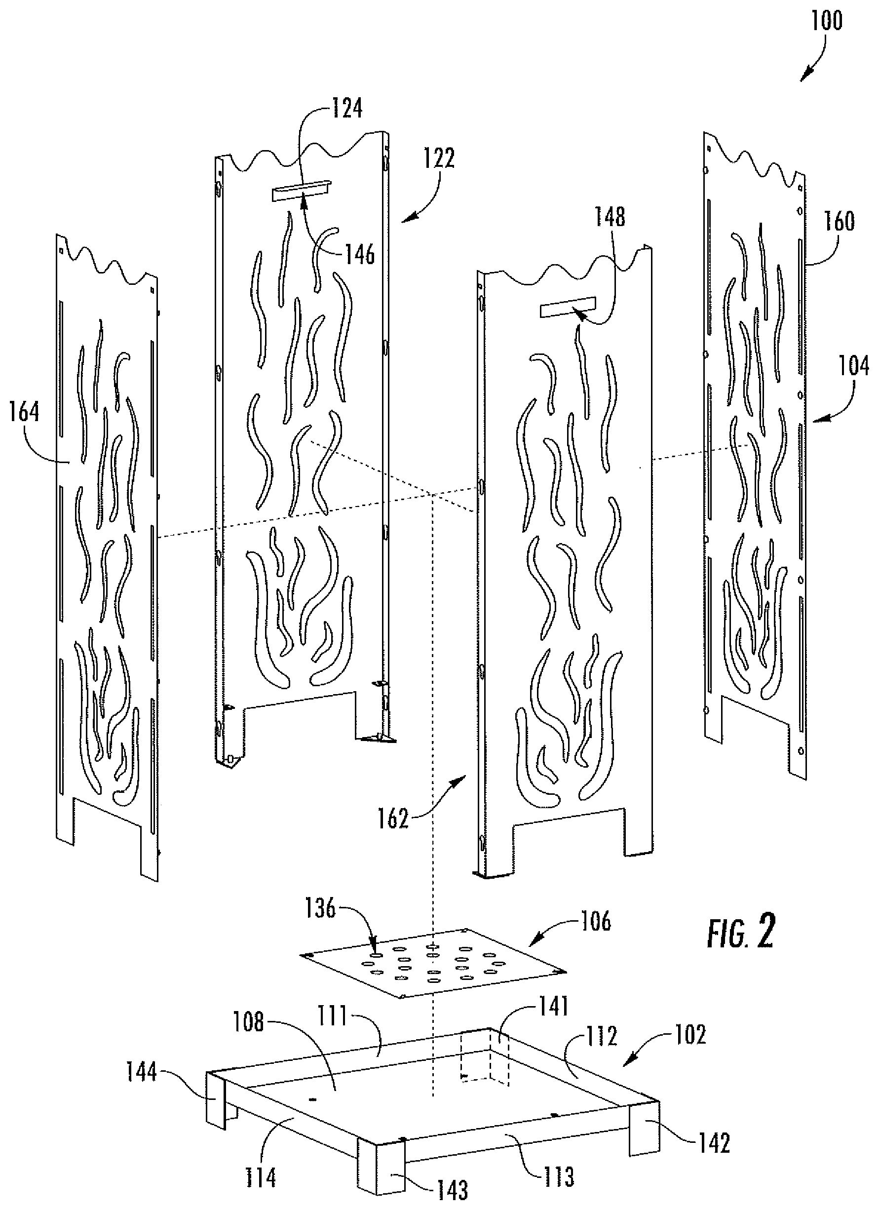
[0014] FIG. 2 is a schematic, assembly diagram depicting various components of the embodiment of FIGS. 1A and 1B.
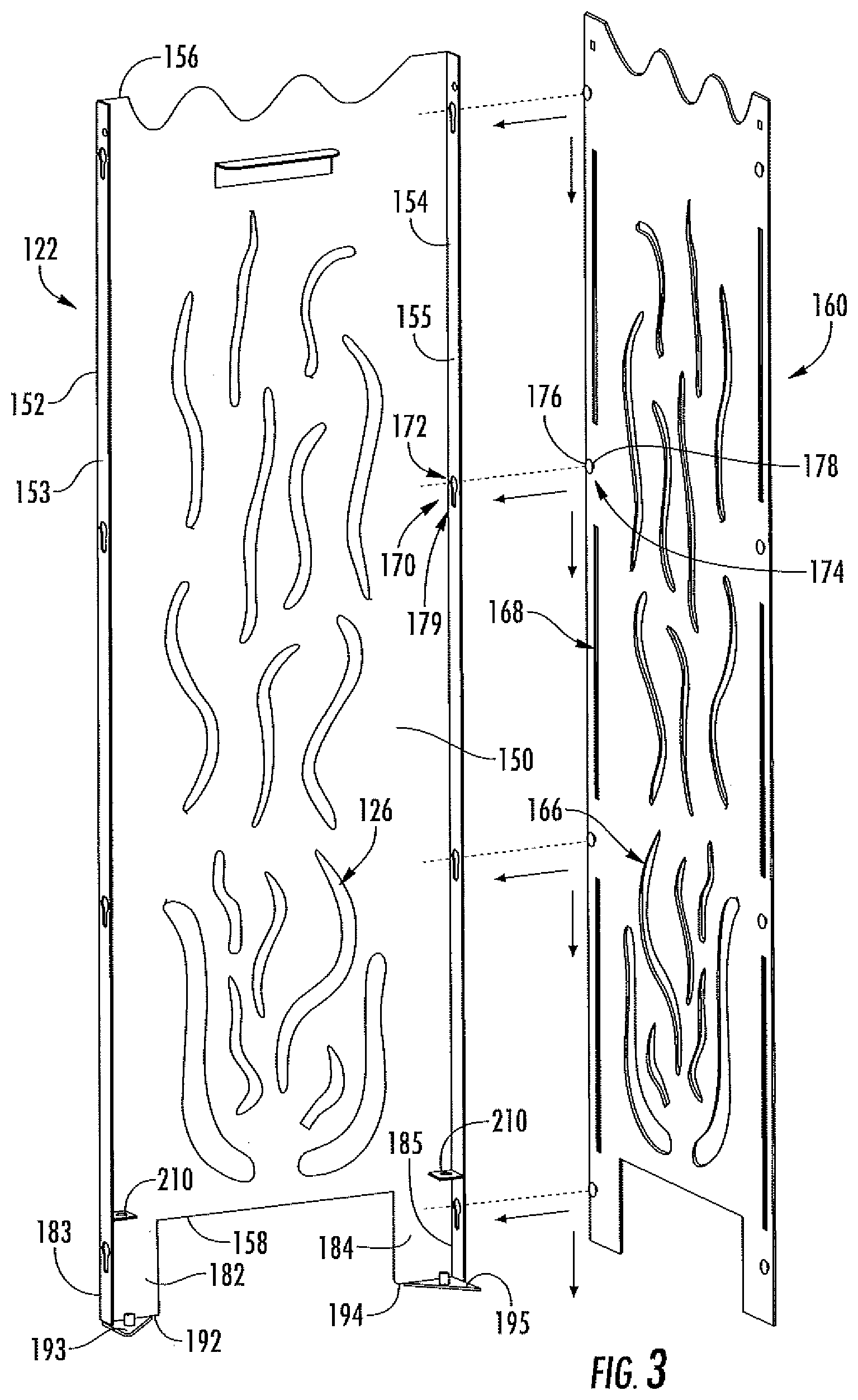
[0015] FIG. 3 is a schematic, assembly diagram of the embodiment of FIGS. 1A, 1B and 2 showing attachment of adjacent panels in greater detail.
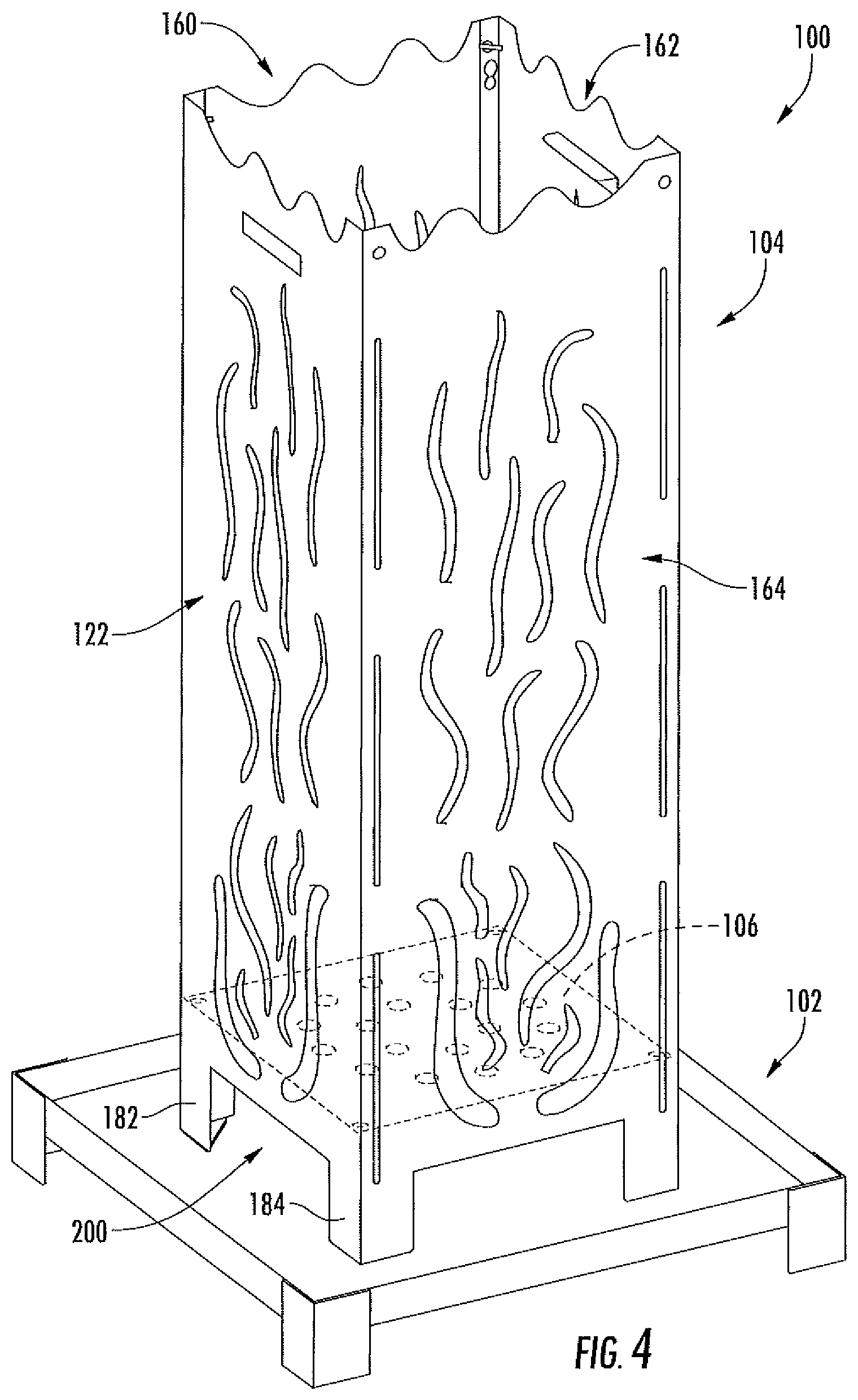
[0016] FIG. 4 is a schematic diagram of the embodiment of FIGS. 1A-3 showing detail of the bottom plate.
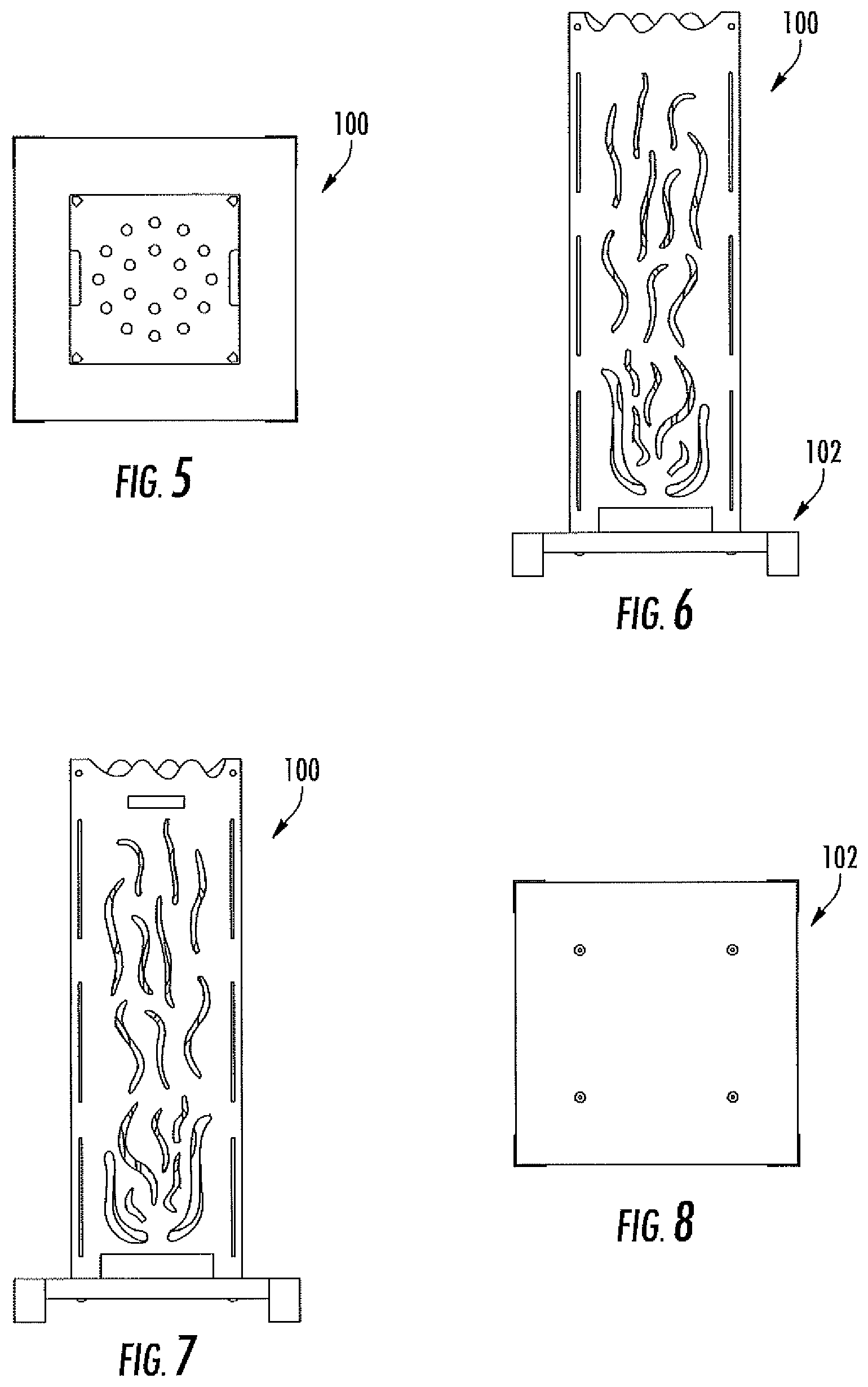
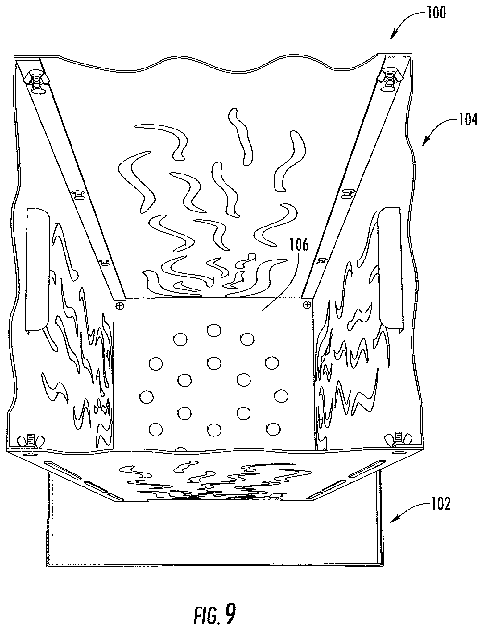
[0017] FIGS. 5-9 are top, front, left side, bottom and top-perspective views, respectively, of the embodiment of FIGS. 1A-4.
DETAILED DESCRIPTION
[0018] For ease in explanation, the following describes several embodiments of fire pit systems. It is to be understood that the invention is not limited in its application to the details of the particular arrangements shown since the invention is capable of other embodiments. Also, the terminology used herein is for the purpose of description and not of limitation.
[0019] In this regard, various embodiments may provide alternatives to conventional fire pit systems. This may be accomplished by a fire pit system that incorporates interlocking panels that may be conveniently assembled. Preferred embodiments will now be described with reference to the drawings.
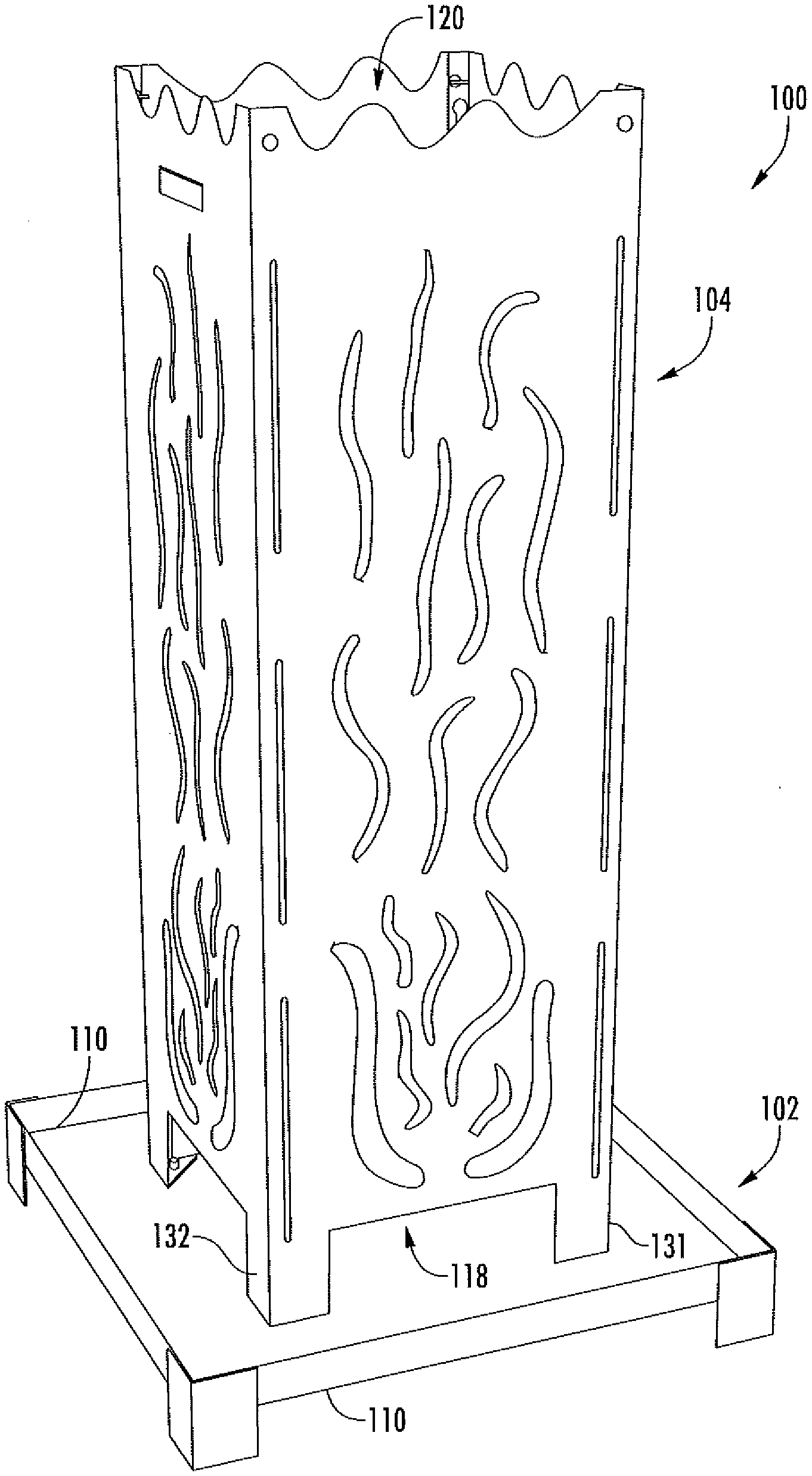
[0020] As shown in FIGS. 1A, 1B and 2, an embodiment of a fire pit system 100 is provided that includes a base 102, a housing 104 and a fire platform 106. Base 102 includes an upper surface 108 and defines an outer perimeter 110. In this embodiment, outer perimeter 110 is rectangular in shape. Barrier walls 111-114 extend upwardly from upper surface 108 along outer perimeter 110 to prevent combustible materials and/or ash from spilling off the base.
[0021] Housing 104 defines an interior 116 within which a fire is intended to burn. Housing 104 also defines a bottom opening 118 and a top opening 120, both of which communicate with interior 106. In this embodiment, housing 104 exhibits a rectangular cross-section and is formed of four interlocking panels (e.g., panel 122) that will be described in greater detail later.
[0022] Housing also incorporates legs (e.g., legs 131 and 132) that are spaced from each other and used to attach the housing to base 102 so that housing 104 extends upwardly from upper surface 108. In particular, the legs are configured to displace bottom opening 118 from upper surface 108 of base 102.
[0023] Fire platform 106 is disposed within interior 116 between bottom opening 118 and top opening 120. Fire platform 106 extends across interior 116 and is configured to support combustible materials placed thereon. In some embodiments, fire platform 106 extends across the entirety of the width and length of the interior. Fire platform 106 also defines openings (e.g., opening 136) that are configured to permit flows of air therethrough.
[0024] Additionally, support legs (141-144) extend downwardly from base 102 and are configured to elevate base 102 from a surface (e.g., the ground) upon which base 102 is positioned. Positioning may be accomplished by a user lifting fire pit system 100 by carry openings 146 and 148, which are defined by housing 104 and positioned between platform 106 and top opening 120. In this embodiment, the carry opening are formed by cut-out portions (e.g., cut-out portion 124) of the metal panels that are bent along a fold line. This configuration, being spaced from the fire, enables the metal in the vicinity of the carry openings to cool more quickly which facilitates convenience of movement. This position may also result in reduced soot accumulation about the carry openings. Further, unlike a conventional fire pit, which incorporates handles near the base, the position of the carry opening towards the top of the fire pit system eases movement by making it unnecessary for the user to bend over as is typically done when attempting to grasp base-level handles.
[0025] As shown in FIG. 3, panel 122 incorporates a body portion 150 which, in this embodiment, is generally elongate and rectangular. Body portion 150 includes opposing side edges 152 and 154, a top edge 156 (which assists in defining top opening 120) and a bottom edge 158 (which assists in defining bottom opening 118). A flange 153 extends outwardly (e.g., perpendicularly) from body portion 150 along side edge 152, while a flange 155 extends outwardly from body portion 150 along side edge 155.
[0026] Panel 122 also incorporates a set of openings (e.g., opening 126) that are disposed above the mounting position of fire platform 106 in order to facilitate air flow into the interior of housing 104. In this embodiment, the openings positioned closer to fire platform 106 are generally of a larger area than those positioned farther from the fire platform to accommodate larger inflows of air closer to fire platform 106.
[0027] Also shown in FIG. 3 is a panel 160, which is configured to interconnect with panel 122 in order to partially form housing 104. Panel 160 also incorporates a set of openings (e.g., opening 166) that are disposed above the mounting position of fire platform 106 in order to facilitate air flow into the interior of housing 104. Unlike panel 122, panel 160 also incorporates elongated slots (e.g., slot 168) that are disposed between the set of openings and the side edges of panel 160. The elongated slots extend along the length of the panel and, in this embodiment, are arranged in opposing pairs.
[0028] In this embodiment, four panels are used to form the housing, with panels 122 and 162 being similarly configured and panels 160 and 164 being similarly configured (FIG. 2). Note that panels positioned adjacent to each other interconnect with each other. In particular, with continued reference to panels 122 and 160 of FIG. 3, flange 155 defines a slot 170 (e.g., a key-hole slot with an enlarged end 172) that is configured to receive therethrough a pin 174 that extends from panel 160. In this embodiment, pin 174 incorporates a head 176 that is wider than its shaft 178 and wider than a narrowed portion 179 of slot 170. So configured, panels 122 and 160 may be moved relative to each other (as depicted by the arrowed lines) to insert pin 174 into slot 170 until head 176 penetrates to the far side of flange 155. Continued movement of the panels relative to reach other causes head 176 to form an interference fit with flange 155, thus interlocking panels 122 and 160 together. Notably, any slots and corresponding pins of the panels may be simultaneously engaged to interlock the panels.
[0029] Additionally, leg portions 182 and 184 extend downwardly from a bottom of panel 122. Leg portion 182 includes an outer side edge 183 that is aligned with side edge 152, and leg portion 184 includes an outer side edge 185 that is aligned with side edge 154. In this embodiment, flange 153 extends downwardly along outer side edge 183, and flange 155 extends downwardly along outer side edge 185.
[0030] Mounting flanges are used to attach panel 122 to base 102. Specifically, mounting flange 193 extends outwardly from a bottom edge 192 of leg portion 182, and mounting flange 195 extends outwardly from a bottom edge 194 of leg portion 184. In this embodiment, the mounting flanges define through-holes through which mechanical fasteners (e.g., bolt and nut assemblies) are attached. The leg portions of each panel assist in defining an airflow path located adjacent to base 102. The airflow path communicates with interior 116 to provide an upwardly directed flow of air toward and through fire platform 106. By way of example, leg portions 182 and 184 of panel 122 assist in defining an airflow path 200.
[0031] As shown in FIGS. 3 and 4, fire platform 106 extends across interior 116 and generally conforms to a shape of the inner surfaces of housing 104. Brackets (e.g., bracket 210) are mounted to the panels to set a height of fire platform 116 within housing 104. In this embodiment, brackets are only affixed to opposing panels 122 and 162. Mechanical fasteners may be used to attach fire platform 116 to the brackets.
[0032] FIGS. 5-9 are top, front, left side, bottom, and top (perspective) views, respectively, of the embodiment of FIGS. 1A-4. In this embodiment, please note that the rear view (not shown) is identical to the front view and the right side view (not shown) is identical to the left side view.
[0033] The embodiments described above are illustrative of the invention and it will be appreciated that various permutations of these embodiments may be implemented consistent with the scope and spirit of the invention.
* * * * *
D00000
D00001
D00002
D00003
D00004
D00005
D00006
D00007
XML
uspto.report is an independent third-party trademark research tool that is not affiliated, endorsed, or sponsored by the United States Patent and Trademark Office (USPTO) or any other governmental organization. The information provided by uspto.report is based on publicly available data at the time of writing and is intended for informational purposes only.
While we strive to provide accurate and up-to-date information, we do not guarantee the accuracy, completeness, reliability, or suitability of the information displayed on this site. The use of this site is at your own risk. Any reliance you place on such information is therefore strictly at your own risk.
All official trademark data, including owner information, should be verified by visiting the official USPTO website at www.uspto.gov. This site is not intended to replace professional legal advice and should not be used as a substitute for consulting with a legal professional who is knowledgeable about trademark law.