Turbine Pumps
STUIVER; Jan ; et al.
U.S. patent application number 16/443034 was filed with the patent office on 2020-12-17 for turbine pumps. The applicant listed for this patent is CECO ENVIRONMENTAL IP INC.. Invention is credited to Erik BURACHINSKY, William PARRY, Steve ROSE, Jan STUIVER.
| Application Number | 20200392960 16/443034 |
| Document ID | / |
| Family ID | 1000004200156 |
| Filed Date | 2020-12-17 |


View All Diagrams
| United States Patent Application | 20200392960 |
| Kind Code | A1 |
| STUIVER; Jan ; et al. | December 17, 2020 |
TURBINE PUMPS
Abstract
Embodiments of pumps are disclosed along with systems and methods relating thereto. In an embodiment, the pump includes a casing assembly that includes a central axis, an upstream connector that is configured to engage with a first connector on a fluid line, and a downstream connector that is configured to engage with a second connector on the fluid line. In addition, the pump includes an impeller rotatably disposed within the casing assembly. Further, the pump includes a driver assembly coupled to the casing assembly and annularly disposed about the impeller. The driver assembly is configured to rotate the impeller about the central axis.
| Inventors: | STUIVER; Jan; (De Knipe, NL) ; BURACHINSKY; Erik; (Dallas, TX) ; PARRY; William; (Dallas, TX) ; ROSE; Steve; (Dallas, TX) | ||||||||||
| Applicant: |
|
||||||||||
|---|---|---|---|---|---|---|---|---|---|---|---|
| Family ID: | 1000004200156 | ||||||||||
| Appl. No.: | 16/443034 | ||||||||||
| Filed: | June 17, 2019 |
| Current U.S. Class: | 1/1 |
| Current CPC Class: | F04D 3/00 20130101; F04D 13/06 20130101 |
| International Class: | F04D 13/06 20060101 F04D013/06; F04D 3/00 20060101 F04D003/00 |
Claims
1. A pump comprising: a casing assembly, wherein the casing assembly includes a central axis and comprises: an upstream connector that is configured to engage with a first connector on a fluid line; and a downstream connector that is configured to engage with a second connector on the fluid line; an impeller rotatably disposed within the casing assembly; and a driver assembly coupled to the casing assembly and annularly disposed about the impeller; wherein the driver assembly is configured to rotate the impeller about the central axis.
2. The pump of claim 1, wherein the impeller comprises an outer housing, a central hub, and a plurality of vanes engaged with and extending between the central hub and the outer housing.
3. The pump of claim 2, wherein the outer housing, the central hub, and the plurality of vanes of the impeller are formed as a monolithic member.
4. The pump of claim 3, wherein the impeller comprises fiberglass.
5. The pump of claim 2, wherein the outer housing is cylindrical in shape and includes a radially inner cylindrical surface and a radially outer cylindrical surface, and wherein each of the plurality of vanes is engaged with the radially inner cylindrical surface.
6. The pump of claim 5, wherein the casing assembly comprises a suction casing and a discharge casing, wherein the suction casing comprises a throughhore that is flush with the radially inner cylindrical surface of the outer housing of the impeller.
7. The pump of claim 5, wherein the central hub includes a first end and a second end opposite the first end, wherein the first end of the central hub includes a hemispherical surface.
8. The pump of claim 5, comprising a plurality of magnets coupled to the radially outer cylindrical surface of the outer housing of the impeller, wherein the driver assembly is configured to induce a varying magnetic field to rotate the impeller and the plurality of magnets about the central axis.
9. The pump of claim 1, further comprising a thermal transfer assembly comprising: a body annularly disposed about the driver assembly; and a cooling coil disposed about the body, wherein the cooling coil comprises an elongate tube that is configured to receive a flow of cooling fluid therethrough.
10. The pump of claim 9, wherein the casing assembly comprises a suction casing and a discharge casing, wherein the body of the thermal transfer assembly is disposed axially between the suction casing and the discharge casing.
11. A system, comprising: a first pipe section; a second pipe section; and a pump mounted between the first pipe section and the second pipe section, wherein the pump comprises: a casing assembly including a central axis; an impeller rotatably disposed within the casing assembly; and a driver assembly coupled to the casing assembly and annularly disposed about the impeller; wherein the driver assembly is configured to rotate the impeller about the central axis to pump fluid from the first pipe section to the second pipe section.
12. The system of claim 11, wherein the impeller comprises: a cylindrical outer housing; a central hub disposed within the outer housing; and a plurality of impeller vanes engaged with and extending between the central hub and the outer housing.
13. The system of claim 12, further comprising: a diffuser disposed within the casing assembly, axially adjacent the impeller, wherein the diffuser is configured to straighten a flow of fluid flowing from the impeller; and wherein the diffuser comprises: a cylindrical outer housing; a central hub disposed within the outer housing of the diffuser; and a plurality of diffuser vanes engaged with and extending between the central hub of the diffuser and the outer housing of the diffuser.
14. The system of claim 11, further comprising a thermal transfer assembly comprising: a body mounted to the casing assembly and disposed annularly about the driver assembly; and a cooling coil disposed about the body, wherein the cooling coil comprises an elongate tube that is configured to receive a flow of cooling fluid therethrough.
15. The system of claim 14, wherein the cooling coil is fluidly coupled to the first pipe section and the second pipe section.
16. A method of pumping a fluid through a fluid line, the method comprising: mounting a pump between a pair of pipe sections of the fluid line, wherein the pump comprises: a casing assembly including a central axis; an impeller rotatably disposed within the casing assembly; and a driver assembly coupled to the casing assembly and annularly disposed about the impeller; rotating the impeller about the central axis with the driver assembly; and flowing a fluid through the pair of pipe sections and the pump while rotating the impeller
17. The method of claim 16, further comprising: straightening a flow of the fluid with a diffuser disposed axially adjacent the impeller
18. The method of claim 16, wherein rotating the impeller comprises: inducing a varying magnetic field with the driver assembly; and attracting a plurality of magnets with the varying magnetic field.
19. The method of claim 16, further comprising: flowing a cooling fluid through a coil that is wrapped about a body of a thermal transfer assembly, wherein the body is mounted to the casing assembly and is disposed annularly about the driver assembly.
20. The method of claim 19, wherein flowing the cooling fluid through the coil comprises: flowing a stream of fluid from a downstream section of the pair of pipe sections to the coil; and flowing the stream of fluid through the coil after; and flowing the stream of fluid from the coil to an upstream section of the pair of pipe section after flowing the stream through the coil.
Description
CROSS-REFERENCE TO RELATED APPLICATIONS
[0001] Not applicable.
STATEMENT REGARDING FEDERALLY SPONSORED RESEARCH OR DEVELOPMENT
[0002] Not applicable.
BACKGROUND
[0003] Fluid pumps may include an impeller that is rotated to pressurize a fluid (e.g., a liquid), Typically the impeller is driven by a motor or other suitable driver. In some circumstances, a pump may be used to pressurize fluid that is corrosive, particularly to metallic materials. In such a service, metallic components of the pump that come into contact with the fluid may experience corrosion, thereby decreasing the lifespan thereof.
SUMMARY
[0004] Some embodiments disclosed herein are directed to a pump. in an embodiment, the pump includes a casing assembly that includes a central axis, an upstream connector that is configured to engage with a first connector on a fluid line, and a downstream connector that is configured to engage with a second connector on the fluid line. In addition, the pump includes an impeller rotatably disposed within the casing assembly. Further, the pump includes a driver assembly coupled to the casing assembly and annularly disposed about the impeller. The driver assembly is configured to rotate the impeller about the central axis.
[0005] Other embodiments disclosed herein are directed to a system. In an embodiment, the system includes a first pipe section, a second pipe section, and a pump mounted between the first pipe section and the second pipe section. The pump includes a casing assembly including a central axis. In addition, the pump includes an impeller rotatably disposed within the casing assembly. Further, the pump includes a driver assembly coupled to the casing assembly and annularly disposed about the impeller. The driver assembly is configured to rotate the impeller about the central axis to pump fluid from the first pipe section to the second pipe section.
[0006] Still other embodiments disclosed herein are directed to a method of pumping a fluid through a fluid line. in an embodiment, the method includes (a) mounting a pump between a pair of pipe sections of the fluid line. The pump includes a casing assembly including a central axis, an impeller rotatably disposed within the casing assembly, and a driver assembly coupled to the casing assembly and annularly disposed about the impeller. In addition, the method includes (b) rotating the impeller about the central axis with the driver assembly. Further, the method includes (c) flowing a fluid through the pair of pipe sections and the pump during (b).
[0007] Embodiments described herein comprise a combination of features and characteristics intended to address various shortcomings associated with certain prior devices, systems, and methods. The foregoing has outlined rather broadly the features and technical characteristics of the disclosed embodiments in order that the detailed description that follows may be better understood. The various characteristics and features described above, as well as others, will be readily apparent to those skilled in the art upon reading the following detailed description, and by referring to the accompanying drawings. It should be appreciated that the conception and the specific embodiments disclosed may be readily utilized as a basis for modifying or designing other structures for carrying out the same purposes as the disclosed embodiments. It should also be realized that such equivalent constructions do not depart from the spirit and scope of the principles disclosed herein.
BRIEF DESCRIPTION OF THE DRAWINGS
[0008] For a detailed description of various exemplary embodiments, reference will now be made to the accompanying drawings in which:
[0009] FIG. 1 is a side view of a pump system according to some embodiments;
[0010] FIG. 2 is a side cross-sectional view of a pump for use in the pump system of FIG. 1 according to some embodiments;
[0011] FIGS. 3 and 4 are side cross-sectional views of a suction casing and a discharge casing, respectively, of the pump of FIG. 2;
[0012] FIG. 5 is a side cross-sectional view of an impeller of the pump of FIG. 2;
[0013] FIG. 6 is a side cross-sectional view of a thermal transfer assembly of the pump of HG.
[0014] FIG. 7 is a side cross-sectional view of a. diffuser of the pump of FIG. 2;
[0015] FIG. 8 is an exploded assembly view of the pump of FIG. 2;
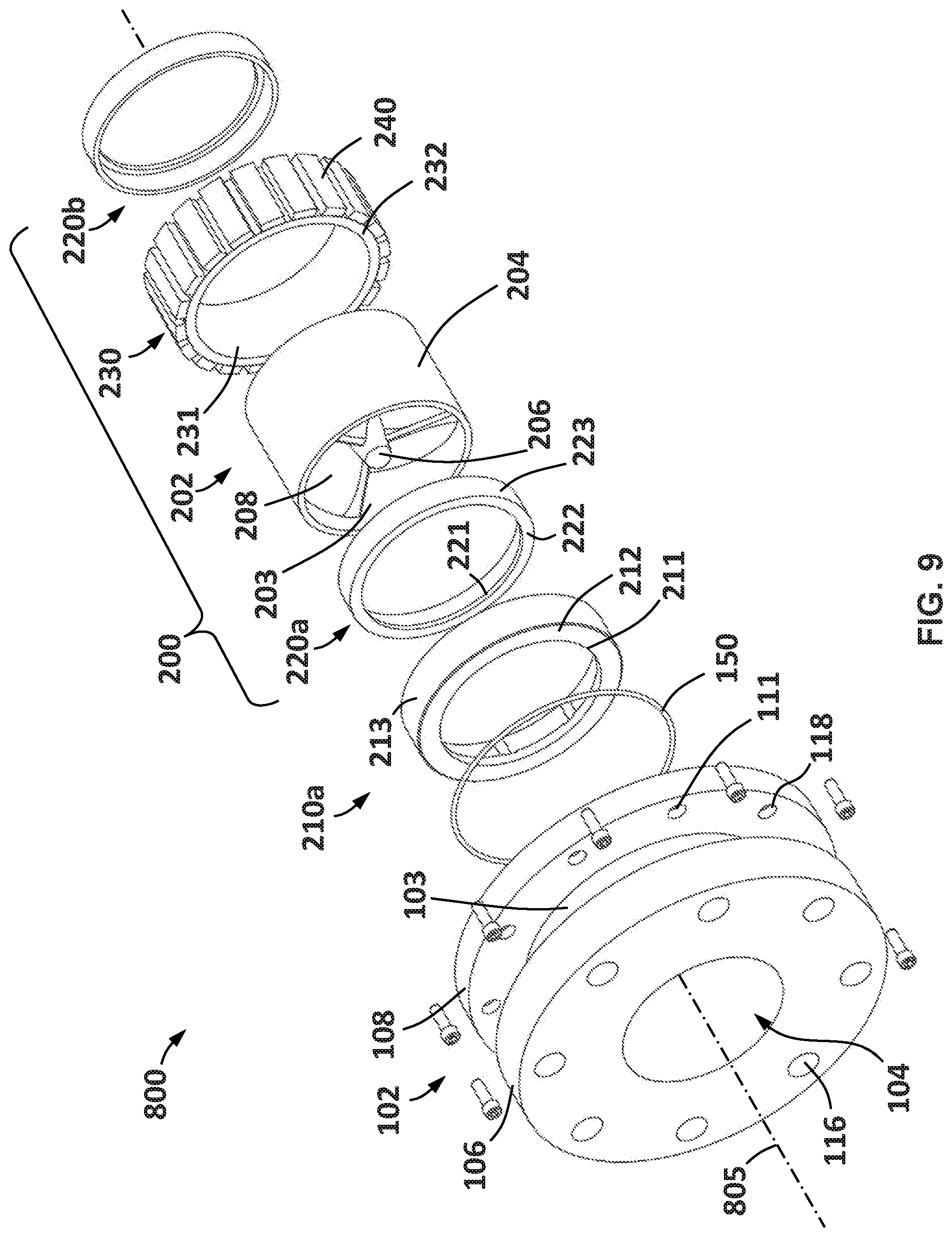
[0016] FIGS. 9 and 10 are exploded assembly views of portions of the pump of FIG. 2;
[0017] FIG. 11 is a cross-sectional view of the pump system of FIG. 1;
[0018] FIGS. 12 and 13 are schematic side views of embodiments of a thermal transfer system for use with the pump of FIG. 2 according to some embodiments;
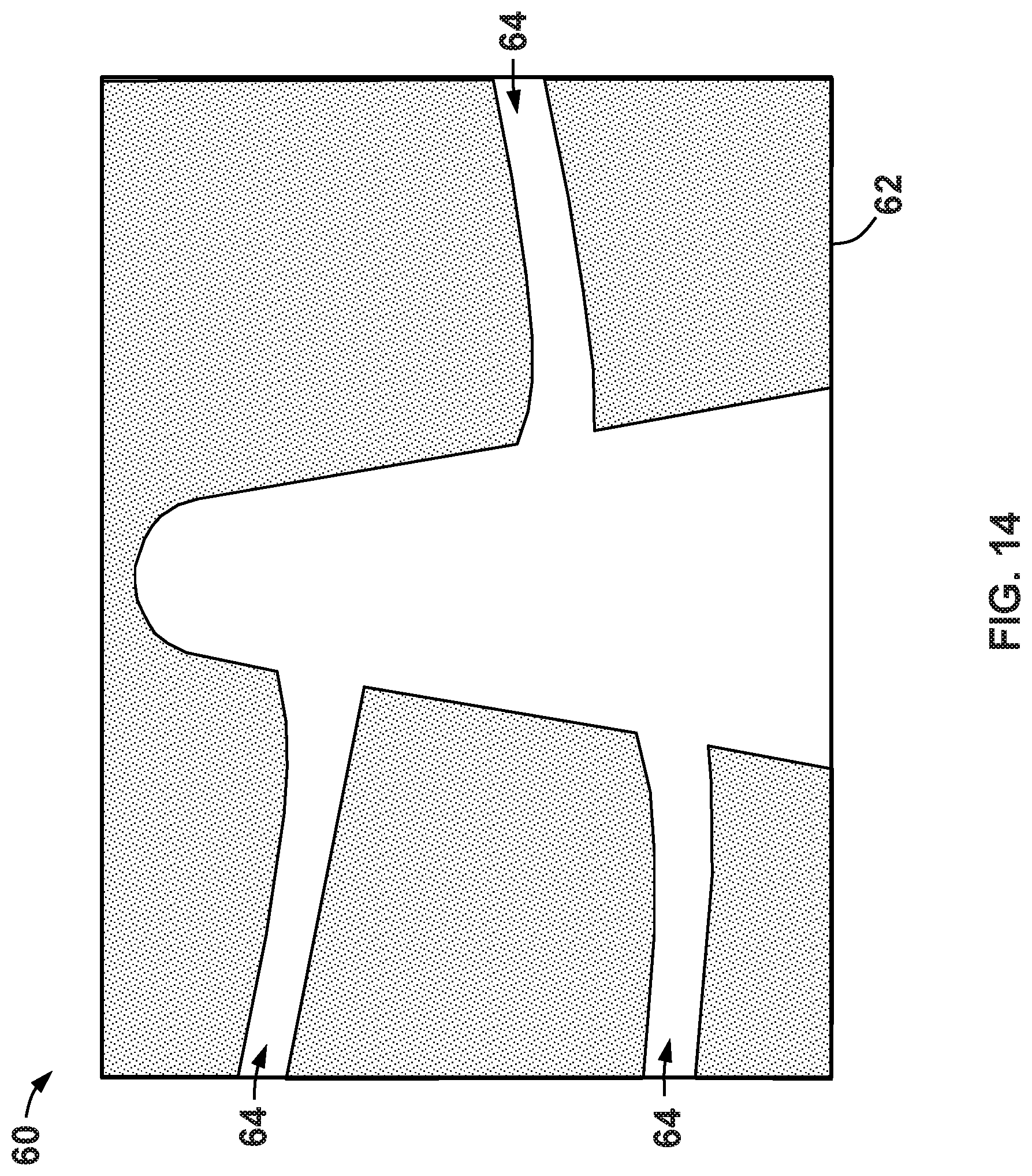
[0019] FIG. 14 is side cross-sectional view of a wax mold core for manufacturing an impeller of the pump of FIG. 2 according to some embodiments; and
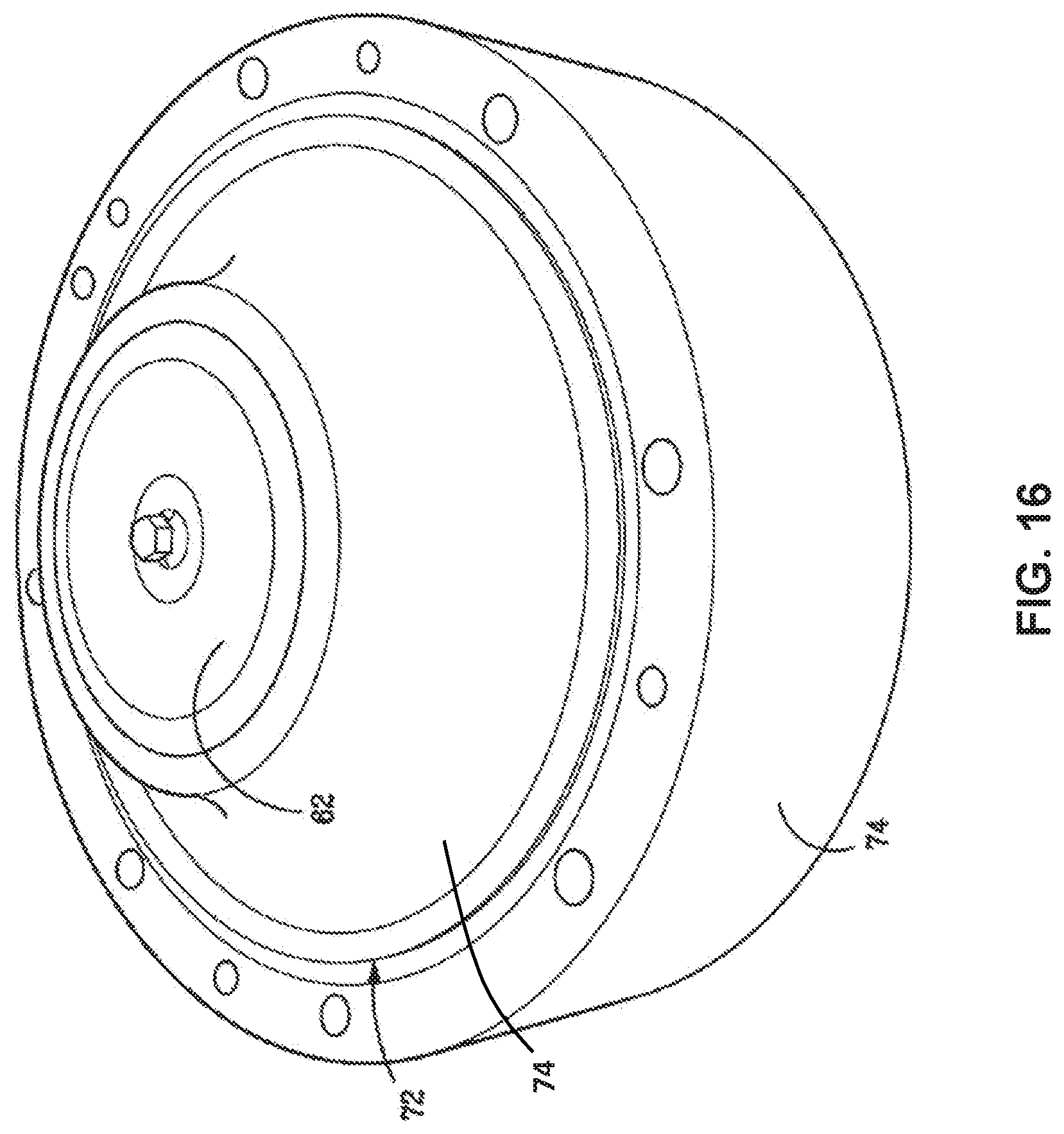
[0020] FIGS. 15 and 16 are sequential perspective views of a molding process utilizing the wax mold core of FIG. 14 according to some embodiments.
DETAILED DESCRIPTION
[0021] The following discussion is directed to various exemplary embodiments. However, one of ordinary skill in the art will understand that the examples disclosed herein have broad application, and that the discussion of any embodiment is meant only to be exemplary of that embodiment, and not intended to suggest that the scope of the disclosure, including the claims, is limited to that embodiment.
[0022] The drawing figures are not necessarily to scale. Certain features and components herein may be shown exaggerated in scale or in somewhat schematic form and some details of conventional elements may not be shown in interest of clarity and conciseness.
[0023] In the following discussion and in the claims, the terms "including" and "comprising" are used in an open-ended fashion, and thus should be interpreted to mean "including, but not limited to . . ." Also, the term "couple" or "couples" is intended to mean either an indirect or direct connection. Thus, if a first device couples to a second device, that connection may be through a direct connection of the two devices, or through an indirect connection that is established via other devices, components, nodes, and connections. In addition, as used herein, the terms "axial" and "axially" generally mean along or parallel to a given axis (e.g., central axis of a body or a port), while the terms "radial" and "radially" generally mean perpendicular to the given axis. For instance, an axial distance refers to a distance measured along or parallel to the axis, and a radial distance means a distance measured perpendicular to the axis. Further, when used herein (including in the claims), the words "about," "generally," "substantially," "approximately," and the like mean within a range of plus or minus 10%.
[0024] As previously described, pumps may include an impeller that is driven or rotated by a separate driver or motor. Typically, the motor and/or the pump is supported on separate base or foundation (e.g., a concrete pad). Therefore, the location of pumps within a facility is typically determined by the available floor spacing for the motor foundation. As a result, additional lengths or runs of piping (or other conduit) may be called for to fluidly couple the fluid lines to the potentially distally disposed pump. Accordingly, embodiments disclosed herein include pumps (e.g., turbine pumps) including an integrated motor or driver that are configured to be coupled within and along a fluid line or pipe. Thus, through use of the embodiments disclosed herein, a foundation or base for the pump (or the associated motor) is no longer included, and the arrangement of the pumps within a facility is greatly simplified.
[0025] Referring to FIG. 1, an embodiment of a pump system 1000 is shown. Generally speaking, system 1000 includes turbine pump 800 (or more generally "pump 800") that is disposed along a fluid line 920. In particular, pump 800 is coupled between and in-line with a pair of pipe or conduit sections 920a, 920b such that a central or longitudinal axis 805 ("axis 805") of pump 800 is aligned with a central axis 925 of fluid line 920. In this embodiment and as will be described in more detail below, pump 800 is configured to induce or drive a flow of fluid along fluid line 920 in a flow direction 950 from pipe section 920a to pipe section 920b. Thus, pipe section 920a may be referred to herein as an "upstream pipe section," and pipe section 920b may be referred to herein as a "downstream pipe section."
[0026] Referring now to FIGS. 2, generally speaking, turbine pump 800 comprises a casing assembly 100, an impeller assembly 200, a driver assembly 300, a diffuser 500, and a thermal transfer assembly 400 all concentrically disposed along axis 805. Driver assembly 300 and thermal transfer assembly 400 are mounted to casing assembly 100 and impeller assembly 200 and diffuser 500 are disposed within casing assembly 100. In general, during operations impeller assembly 200 is rotated about axis 805 by driver assembly 300 to pressurize a fluid (e.g., a liquid) within fluid line 920 (see e.g., FIG. 1) so that the fluid is flowed from upstream pipe section 920a toward and through downstream pipe section 920b along flow direction 950 as previously described. As will be described in more detail below, some or all of the components of pump 800 may be constructed from non-metallic materials so as to decrease the overall weight of pump 800 and to avoid corrosion due to contact with potentially corrosive fluids flowing therethrough (e.g., salt water).
[0027] Referring now to FIGS. 2-4 and 8, casing assembly 100 includes a first or suction casing 102 and a second or discharge casing 120. Referring specifically to FIGS. 3 and 9, suction casing 102 includes a first or upstream end 102a, a second or downstream end 102b opposite upstream end 102a, and a throughbore 104 extending axially between ends 102a, 102b. In addition, suction casing 102 includes a first or upstream connector 106 at upstream end 102a, a second or downstream connector 108 proximate to downstream end 102b, a cylindrical body 103 extending axially between connectors 106, 108, and a cylindrical projection or lip 107 extending axially from downstream connector 108 to downstream end 102b. A seal gland 114 extends radially inward into lip 107 that receives a sealing member (e.g., O-ring) 150 therein.
[0028] Connectors 106, 108 may be any suitable device or structure for coupling with a corresponding connector or device on fluid line 920 or within pump 800 (see e.g., FIG. 1), such as, for example, flanges, couplings, threaded connectors, etc. In this embodiment, connectors 106, 108 comprise flanges. Upstream connector 106 includes a planar engagement face or surface 106a, and downstream connector 108 includes a planar engagement face or surface 108a. Engagement surface 108a of downstream connector 108 includes an axially extending circumferential groove or channel 112. In addition, a plurality of bolt holes 116 and bolt holes 118 may be provided through upstream connector 106 and downstream connector 108, respectively. Note that only one of the bolt holes 116 and one of the bolt holes 118 are visible in FIGS. 2 and 3 due to the arrangement of the cross-sectional views shown therein.
[0029] A radially extending downstream facing annular shoulder 109 ("shoulder 109") is disposed within throughbore 104 such that throughbore 104 includes a first or upstream section 104a extending axially from upstream end 102a to shoulder 109 and second or downstream section 104b extending axially form shoulder 109 to downstream end 102b. Downstream section 104b has a larger inner diameter than upstream section 104a.
[0030] Referring specifically to FIGS. 4 and 10, discharge casing 120 includes a first or upstream end 120a, a second or downstream end 120b opposite upstream end 120a, and a throughbore 124 extending axially between ends 120a, 120b. In addition, discharge casing 120 includes a first or upstream connector 128 proximate to upstream end 120a, a second or downstream connector 126 at downstream end 120b, a cylindrical body 123 extending axially between connectors 128, 126, and a cylindrical projection or lip 127 extending axially from upstream connector 128 to upstream end 120a. A seal gland 134 extends radially inward into cylindrical projection 127 that receives a sealing member (e.g., O-ring) 152 therein.
[0031] Connectors 126, 128 may similar to connectors 106, 108, previously described for suction casing 102 (see e.g., FIGS. 2 and 3). Thus, connector 126, 128 may be any suitable device or structure for coupling with a corresponding connector or device on fluid line 920 or within pump 800. In this embodiment, connectors 126, 128 comprise flanges. Downstream connector 126 includes a planar engagement face or surface 126a, and upstream connector 128 includes a planar engagement face or surface 128a. Engagement surface 128a of upstream connector 128 includes an axially extending circumferential groove or channel 132. In addition, a plurality of bolt holes 140 and bolt holes 142 may be provided through upstream connector 128 and downstream connector 126, respectively, Note that only one of the bolt holes 140 and one of the bolt holes 142 are visible in FIGS. 2 and 4 due to the arrangement of the cross-sectional views shown therein.
[0032] A radially extending annular projection 136 ("projection 136") is disposed within throughbore 124 so that throughbore 124 includes a first or upstream section 124a extending axially from upstream end 120a to projection 136 and second or downstream section 124b extending axially from projection 136 to downstream end 120b. Projection 136 defines a first or upstream facing annular shoulder 137 and a second or downstream facing annular shoulder 139. Upstream section 124a has a larger inner diameter than downstream section 124b. Also, a radially extending annular recess 138 is disposed within downstream section 124b of throughbore 124.
[0033] Referring now to FIGS. 2, 5, 8, and 9, impeller assembly 200 generally includes an impeller 202, a pair of impeller wear rings 220a, 220b and a magnet assembly 230. Referring specifically to FIG-S. 5 and 9, impeller 202 comprises an outer housing 204, a central hub 206 disposed within outer housing 204, and a plurality of impeller vanes 208 (or more simply "vanes 208") extending between central hub 206 and outer housing 204.
[0034] In this embodiment, outer housing 204 is a cylindrical member that includes a first or upstream end 204a, a second or downstream end 204b opposite upstream end 204a. In addition, outer housing 204 includes a radially outer cylindrical surface 201 and a radially inner cylindrical surface 203 both extending axially between ends 204a, 204b. In other embodiments, outer housing 204 (or a portion thereof), may be non-cylindrical in shape,
[0035] Referring specifically to FIGS. 5 and 9, central hub 206 is a solid member (non-hollow) that is disposed within outer housing 204 along axis 805 and includes a first or upstream end 206a, a second or downstream end 206b opposite upstream end 206a. Upstream end 206a is proximate upstream end 204a of outer housing 204, and downstream end 206b is disposed at downstream end 204b of outer housing 204. In this embodiment, central hub 206 is generally.sup., conical in shape and thus includes a varying cross-section between ends 206a, 206b. In particular, the circumference and diameter of central hub 206 progressively increase between ends 206a and 206b. In addition, in this embodiment upstream end 206a includes a rounded or hemispherical surface 207. Without being limited to this or any other theory, the hemispherical surface 207 may reduce turbulence for the fluid flowing within outer housing 204 and the generally conical shape of central hub 206 may progressively decrease the flow area within outer housing 204 for fluids flowing from upstream end 204a toward downstream end 204b. This decrease in the flow area may increase the localized flow rate along axis 805 and the pressure of the fluid flowing through impeller 202 during operations. It should be appreciated that other shapes and profiles are contemplated for central hub 206. For example, in some embodiments, central hub 206 may include non-linear cross-section changes (e.g., a parabolic).
[0036] Vanes 208 extend generally radially from central hub 206 to radially inner cylindrical surface 203 of outer housing 204. In some embodiments, vanes 208 are circumferentially spaced (e.g., uniformly circumferentially spaced) about axis 805. In addition, all or some of the vanes 208 may be axially spaced from one another along axis 805. In this embodiment, there are total three vanes 208, that are circumferentially spaced approximately 120.degree. from one another about axis 805; however, other numbers and spacing are contemplated for vanes 208 in other embodiments. In addition, each of the vanes 208 of this embodiment extend generally helically (e.g., along a constant or varying helical pitch) about central hub 206 between ends 206a, 206b..
[0037] As best shown in FIG. 5, in this embodiment, each of the vanes 208 is generally curved between central hub 206 and radially inner cylindrical surface 203 of outer housing 204. In particular, each vane 208 generally curves in an upstream direction, or toward upstream ends 206a, 204a of central hub 206 and outer housing 204 when moving radially outward from central hub 206 toward radially inner cylindrical surface 203. However, it should be appreciated that vanes 208 may extend generally linearly between central hub 206 and radially inner cylindrical surface 203 in other embodiments. In addition, in this embodiment the axial thickness of each vane 208 generally decreases when moving from central hub 206 toward radially inner cylindrical surface 203. However, again, in other embodiments, the axial thickness of vanes 208 may be generally constant between central hub 206 and radially inner cylindrical surface 203. Further, while not specifically shown it should be appreciated that the axial thickness of each vane 208 may vary (e.g., increase and/or decrease) or may remain generally constant between its corresponding upstream and downstream ends. Still further, in some embodiments local cross-sectional variations may be included along vanes 208 to optimize flow characteristics through impeller 202 during operations.
[0038] In some embodiments the generally helical configuration of vanes 208 may vary along the axial direction (e.g., along axis 805, between ends 206a, 206b) and/or along the radial direction (e.g., radially between central hub 206 and radially inner cylindrical surface 203 of outer housing 204). For instance, in some embodiments vanes 208 may have a varying helical pitch along the axial length between ends 206a, 206b. Generally speaking, as the helical pitch increases the vanes 208 axially advance a greater distance along axis 805 for a given amount of angular twist about axis 805. Thus, in some embodiments the helical pitch of vanes 208 at the first end 206a is different from the helical pitch of vanes 208 at second end 206b. Additionally or alternatively, in some embodiments vanes 208 may have helical pitch which varies as a function of radial position between central hub 206 and radially inner cylindrical surface 203. For example, the helical pitch of vanes 208 may increase and/or decrease when moving radially from the attachment central hub 206 and the radially inner cylindrical surface 203. However, it should be appreciated that other variations of the helical pitch of vanes 208 (as well as other parameters) are contemplated herein.
[0039] Referring still to FIGS. 5 and 9, in this embodiment, outer housing 204, central hub 206 and vanes 208 are all formed as a monolithic piece or member (i.e., impeller 202). Thus, in some embodiments, outer housing 204, central hub 206, and vanes 208 may comprise the same material(s) (e.g., fiberglass). During operations, the impeller 202 (including outer housing 204, central hub 206, and vanes 208) generally rotates about axis 805 to increase the pressure and velocity of the fluid flowing therethrough. In this embodiment, impeller 202 is symmetrical about axis 805 such that its rotating moment of inertia is concentric about axis 805. In addition because vanes 208 are monolithically formed with outer housing 204 and central hub 206 as previously described, fluids flowing through impeller 202 (e.g., between ends 204a, 204b of outer housing 204 are prevented from flowing between outer housing 204 and vanes 208 and between vanes 208 and central hub 206. Accordingly, the fluid is forced to flow in a generally helical or twisting path about axis 805 between vanes 208 as it flows axially between ends 204a, 204b of outer housing 204.
[0040] Referring still to FIGS. 5 and 9, each impeller wear ring 220a, 220b includes an annular base 222 including a central aperture 221 extending axially therethrough, and a cylindrical sleeve 223 extending axially from annular base 222. Each of the impeller wear rings 220a, 220b are disposed on outer housing 204 of impeller 202, such that wear ring 220a is disposed over upstream end 204a of outer housing 204, and wear ring 220b is disposed over downstream end 204b of outer housing 204. In particular, upstream end 204a of outer housing 204 is received within wear ring 220a such that radially outer cylindrical surface 201 is engaged with the corresponding cylindrical sleeve 223 and upstream end 204a is engaged with the corresponding annular base 222. Similarly, downstream end 204b of outer housing 204 is received within wear ring 220b such that radially outer cylindrical surface 201 is engaged with the corresponding cylindrical sleeve 223 and downstream end 204b is engaged with the corresponding annular base 222. In addition, once mounted to outer housing 204 as described above, central apertures 221 in wear rings 220a, 220b are aligned with radially inner surface 203. Thus, in this embodiment central apertures 221 are flush with radially inner cylindrical surface 203.
[0041] Referring still to FIGS. 5 and 9, magnet assembly 230 comprises a cylindrical ring or sleeve 232, and a plurality of magnets 240 mounted to sleeve 232. In particular, sleeve 232. includes an axially extending radially inner cylindrical surface 231 and an axially extending radially outer cylindrical surface 233. The plurality of magnets 240 are mounted to radially outer cylindrical surface 233. In particular, magnets 240 are uniformly circumferentially spaced along radially outer cylindrical surface 233 relative to axis 805. In this embodiment, magnets 240 are permanent magnets; however, it should be appreciated that in other embodiments magnets 240 may comprise electrically conductive materials (e.g., aluminum bars) such as may found within an induction rotor, or may comprise one or more electro-magnetic coils (e.g., conductive coils or windings, such as cooper, surrounding a ferromagnetic or ferromagnetic core, such as iron).
[0042] As best shown in FIG. 5, magnet assembly 230 is disposed about outer housing 204 of impeller 202 such that radially inner surface 231 of sleeve 232 is engaged with radially outer cylindrical surface 201 of outer housing 204. in addition, in this embodiment, sleeve 232 is positioned axially between wear rings 220a, 220b such that sleeve 232 is axially spaced from cylindrical sleeves 223 of each ring 220a, 201), Further, in this embodiment, sleeve 232 is generally axially centered between ends 204a, 204b of outer housing 204. Sleeve 232 may be secured to radially outer cylindrical surface 201 of outer housing 204 in any suitable fashion. For example, in some embodiments, sleeve 232 may be secured to outer housing 204 via a friction fit. In addition, in other embodiments, sleeve 232 may be welded, brazed, adhered (e.g., with an adhesive) or otherwise secured to outer housing 204.
[0043] Referring again to FIG. 2, during operations, impeller assembly 200 is disposed axially between suction casing 102 and discharge casing 120. In particular, a pair of casing wear rings 210a, 210b are disposed within throughbores 104, 124 of casings 102, 120, respectively. Each casing wear ring 210a, 210b includes an annular base 212 including a central aperture 211 extending axially therethrough, and a cylindrical sleeve 213 extending axially from base 212 Casing wear ring 210a is received within downstream section 104b of throughbore 104 of suction casing 102 such that the corresponding annular base 212 is engaged with annular shoulder 109 and the corresponding central aperture 211 is generally aligned and flush with upstream section 104a of throughbore 104. Similarly, casing wear ring 210b is received within downstream section 124b of throughbore 124 of discharge casing 120 such that the corresponding base 212 is engaged with upstream facing annular shoulder 137.
[0044] As shown in FIG. 2, impeller assembly 200 is received within casing assembly 100 such that impeller wear ring 220a is received within casing wear ring 210a and impeller wear ring 220b is received within casing wear ring 210b. In particular, cylindrical sleeves 223 of wear rings 220a, 220b may slidingly engage with cylindrical sleeves 213 of casing wear rings 210a, 210b, respectively, and central apertures 221 and 211 of wear rings 220a, 220b, and 210a, 210b, are generally flush with one another along axis 805. As will be described in more detail below, during operations, impeller assembly 200 rotates about axis 805 within casing assembly 100 such that wear rings 220a, 220b rotate within and relative to casing wear rings 210a, 210b, respectively. Accordingly, direct contact between outer housing 204 of impeller and casings 102, 120 is avoided, and wear rings 210a, 210b, 220a, 220b may be considered wear parts that are replaced at regular intervals.
[0045] Referring still to FIGS. 2 and 10, driver assembly 300 is annularly disposed about magnet assembly 230 and is axially positioned between suction casing 102 and discharge casing 120. In particular, as shown in FIG, 2 driver assembly 300 is disposed over the cylindrical projections 107, 127, and is axially disposed between planar engagements faces 108a, 128a of connectors 108, 128 of casings 102, 120, respectively. In addition, a sealing sleeve 330 is disposed radially between cylindrical projections 107, 127 of casings 102, 120 and driver assembly 300, such that sealing members 150, 152 are radially compressed within seal glands 114, 134 of casings 102, 120 (see e.g., FIGS. 3 and 4). Thus, fluids are prevented (or at least restricted) from flowing between seal sleeve 330 and cylindrical projections 107, 127 during operations.
[0046] In this embodiment driver assembly 300 defines a plurality of windings or coils 304 of conductive wire (e.g., conductive coils or windings, such as cooper, surrounding a ferromagnetic or ferromagnetic core, such as iron) that are disposed or arranged circumferentially about axis 805. Generally speaking, during operations, electrical current may be routed through the conductive coils 304 so as to induce varying magnetic fields. As will be described in more detail below, the induced magnetic fields within driver assembly are configured to drive rotation of impeller assembly 200 about axis 805 within casing assembly 100 during operations.
[0047] It should be appreciated that driver assembly 300 may include alternative designs in other embodiments. For instance, in some embodiments, windings 304 may be replaced with a plurality of permanent magnets arranged circumferentially around axis 805, or a plurality of electrically conductive members (e.g., aluminum bars) such as might be used within an induction motor.
[0048] Referring now to FIGS. 2, 6, and 9, thermal transfer assembly 400 includes heat sink or body 402 and a cooling coil 420 circumferentially wrapped around body 402. Body 402 includes a first or upstream end 402a, a second or downstream end 402b opposite upstream end 402a, and a throughbore 401 extending axially between ends 402a, 402b that is defined by a radially inner cylindrical surface 407. In addition, body 402 includes a first or upstream connector 404 proximate upstream end 402a, a second or downstream connector 406 proximate downstream end 402b, and a radially outer cylindrical surface 403 extending axially between connectors 404, 406. Connectors 406, 408 may comprise any suitable structure or device for mating with another component or member. For instance, in this embodiment connectors 404, 406 comprises flanges that each include a plurality of mounting bores 410 extending axially therein (note: only one of the mounting bores 410 are visible in each of the connectors 404, 406 in FIGS. 2 and 6 due to the arrangement of the cross-sectional views shown therein) Further, in this embodiment body 402 includes a first or upstream lip 409a extending axially upstream connector 404 to upstream end 402a, and a downstream second lip 409b extending axially from downstream connector 406 to downstream end 402b. Lips 409a, 409b may also be generally referred to herein as "axial projections 409a, 409b."
[0049] Cooling coil 420 comprises an elongate tube or conduit that is wrapped (e.g., helically) about radially outer surface 403 of body 402. Cooling coil 420 may comprise any suitable material, and in some embodiments may comprise a conductive material (e.g., a metal) so as to conduct thermal energy away from body 402 during operations. As will be described in more detail below, during operations a cooling fluid (e.g., diverted fluid from fluid line 920, a separate cooling fluid, etc.) is flowed or routed through cooling coil 420 to facilitate convective heat transfer, In this embodiment, cooling coil 420 comprises includes a circular cross-section; however, other cross-sections are contemplated (e.g., elliptical, rectangular, square, etc.).
[0050] Body 402 may be constructed from any suitable material, and in sonic embodiments may be made of a material having a high thermal conductivity (e.g., having a coefficient of thermal conductivity above 5-W/m.degree. K). In addition, in sonic embodiments, body 402 may be made from a non-magnetic or possibly a weakly magnetic material (e.g., aluminum, 316 stainless, nickel alloys, alumina filled epoxy, etc.). In some embodiments, there may be intimate contact between cooling coil 420 and radially outer cylindrical surface 403 of body 402 since increased contact areas and compressive forces may increase the heat flow capacity between body 402 and cooling coil 420 during operations. In some embodiments, ridges, fins or other suitable projections may be disposed along body 402 (particularly along radially outer surface 403) to increase the circumferential contact area between each segment of cooling coil 420 and body 402. In addition, in some embodiments, increased contact may be achieved between cooling coil 420 and body 402 by tightly wrapping cooling coil 420 around body 402 and/or by applying an external clamp (not shown) around the perimeter of cooling coil 420.
[0051] Referring again to FIG. 2, thermal transfer assembly 400 is engaged axially between connectors 108, 128 of casings 102, 120, respectively. In particular, upstream connector 404 on body 402 is engaged with planar engagement surface 108a on downstream connector 108 of upstream casing and downstream connector 406 on body 402 is engaged with engagement surface 128a on upstream connector 128 of discharge casing 120. In addition, upstream lip 409a is received within circumferential groove 112 in planar engagement face 108a, and downstream lip 409b is received within circumferential groove 132 in planar engagement face 128a. Further, a plurality of fasteners 160 (e.g., bolts) are received within aligned pairs of the bolt holes 118 on connector 108 of suction casing 102 and the mounting bores 410 on upstream connector 404 and within aligned pairs of the bolt holes 140 on upstream connector 128 and the mounting bores 410 on downstream connector 406. In this embodiment, the fasteners extend through bolt holes 118, 140 and are threadably engaged with the corresponding mounting holes 410 so as to secure body 402 axially between each of the casings 102, 120.
[0052] In this embodiment, when thermal transfer assembly 400 is mounted between casings 102, 120 as described above, radially inner surface 407 of body 402 may contact (or is closely positioned) to driver assembly 300 (particularly coils 304). Thus, as will be described in more detail below, heat which is generated within coils 304 during operations may be transferred (e.g., conducted, radiated, etc.) to body 402 and then further transferred away from pump 800 via cooling coil 420 as noted above.
[0053] Referring still to FIGS. 2, 7, and 9, diffuser 500 comprises an outer housing 502, a central hub 506, and a plurality of diffuser vanes 508 (or more simply "vanes 508") extending between central hub 506 and outer housing 502.
[0054] In this embodiment, outer housing 502 is a cylindrical member that includes a first or upstream end 502a, a second or downstream end 502b opposite upstream end 502a. In addition, outer housing 502 includes a radially outer cylindrical surface 504 and a radially inner cylindrical surface 503 both extending axially between ends 502a, 502b. In other embodiments, outer housing 502 (or a portion thereof), may be non-cylindrical in shape.
[0055] Referring still to FIGS. 2, 7, and 9, central hub 506 is a solid member (non-hollow) disposed within outer housing 502 along axis 805 and includes a first or upstream end 506a, a second or downstream end 506b opposite upstream end 506a. Upstream end 506a extends axially past upstream end 502a of outer housing 502, and downstream end 506b is disposed at downstream end 502b of outer housing 502. In addition, central hub 506 includes a first or upstream section 507 extending axially from upstream end 506a, and a second or downstream section 509 extending axially from upstream section 507 to downstream end 506b. Upstream section 507 is generally cylindrical in shape, while downstream section 509 is generally conical in shape. Thus, of diffuser 500 may include a varying cross-section between ends 502a, 502b. In this embodiment, the circumference and diameter of central hub 506 is generally constant within upstream section 507, and generally decreases when moving axially within downstream section 509 from upstream section 507 to downstream end 506b. In addition, in this embodiment downstream end 506b includes a rounded or hemispherical surface 510. Without being limited to this or any other theory, the hemispherical surface 510 may reduce turbulence for the fluid flowing within outer housing 502 and the generally conical shape of downstream section 509 of central hub 506 may progressively increase the flow area within outer housing 502 for fluids flowing from upstream end 502a toward downstream end 502b. It should be appreciated that other shapes and profiles are contemplated for central hub 506. For example, in some embodiments, central hub 506 may include non-linear cross-section changes (e.g., a parabolic).
[0056] Referring specifically now to FIG. 7, vanes 508 extend generally radially outward from central hub 506 to radially inner surface 503 of outer housing 502. Each vane 508 includes a first or upstream end 508a and a second or downstream end 508b opposite upstream end 508a. Upstream end 508a is proximate upstream end 502a of outer housing 502 and downstream end 508b is proximate downstream end 502b of housing 502. In some embodiments, vanes 508 are circumferentially spaced (e.g., uniformly circumferentially spaced) about axis 805. In this embodiment, there are total four vanes 508, that are circumferentially spaced approximately 90.degree. from one another about axis 805; however, other numbers and spacing are contemplated for vanes 508 in other embodiments. In addition, each of the vanes 508 of this embodiment are configured to generally convert a twisting or helical flow pattern for a fluid (e.g., such as a fluid that has flowed across impeller 202 previously described) into a generally axial or laminar flow pattern. That is, vanes 508 are configured to straighten the fluid flowing from impeller 202. Thus, in this embodiment, each vane 508 extends generally helically at upstream end 508a, but then progressively transitions to a generally axial orientation at downstream end 508b. In one embodiment, the upstream end 508a vanes 508 may generally correspond (e.g., having a similar or equal helical angle, pitch, etc.) to the helical direction or shape of vanes 208 of impeller 202 (see e.g., FIGS. 2 and 5) such that fluid flowing past impeller 200 is efficiently captured by diffuser 500, during operations.
[0057] Referring still to FIG. 7, in this embodiment, vanes 508 extend generally helically along portions of central hub 506 proximate to upstream end 508a and couple with radially inner surface 503 of housing 502. In addition, in this embodiment the axial thickness of each vane 508 generally decreases when moving from central hub 506 toward radially inner surface 503. However, again, in other embodiments, the axial thickness of vanes 508 may be generally may be constant between central hub 506 and radially inner surface 503. Further, while not specifically shown it should be appreciated that the axial thickness of each vane 508 may vary (e.g., increase and/or decrease) or may remain generally constant between its corresponding upstream and downstream ends 508a, 508b, respectively. Still further, in some embodiments local cross-sectional variations may be included along vanes 508 to optimize flow characteristics through diffuser 500 during operations. Also, in substantially the same manner as was previously described for the vanes 208 of impeller 200, in some embodiments the general helical shape of vanes 508 of diffuser 500 (e.g., for the portion of vanes 508 proximate upstream end 508a) may vary (e.g., in helical pitch) along the axial direction and/or the radial direction with respect to axis 805.
[0058] In this embodiment outer housing 502, central hub 506, and vanes 508 are all monolithically formed as a single piece or member (i.e., diffuser 500). Thus, in some embodiments, outer housing 502, central hub 506, and vanes 508 may comprise the same material(s) (e.g., fiberglass). During operations, fluid is flowed over the diffuser 500 (including outer housing 502, central hub 506, and vanes 508) to transition the flow pattern of the fluid from helical or twisting to laminar (or more laminar). Because vanes 508 are monolithically formed with outer housing 502 and central hub 506 as previously described, fluids flowing through diffuser 500 (e.g., between ends 502a, 502b of outer housing 502) are prevented from flowing between outer housing 502 and vanes 508 and between vanes 508 and central hub 506. Accordingly, the fluid is forced to flow over vanes 508 as it flows axially between ends 502a, 502b of housing 502.
[0059] Referring again to FIG. 2, diffuser 500 is inserted within downstream section 124b of throughbore 124 in discharge casing 120 during operations. In particular, diffuser 500 is inserted axially into downstream section 124b of throughbore 124 from downstream end 120b of casing 120 until upstream end 502a of outer housing 502 engages with downstream facing annular shoulder 139, and upstream end 506a of central hub 506 approaches downstream end 206b of central hub 206 along axis 805. Thereafter a retaining ring 520 is inserted within throughbore 124 (particularly downstream section 124b) and is radially expanded into annular recess 138. Thus, during operations, diffuser 500 is prevented from axially translating out downstream section 124b of throughbore 124 by engaging with retaining ring 520.
[0060] Referring now to FIGS. 1 and 11, during operations, turbine pump 800 is mounted within a fluid line (e.g., fluid line 920). In particular, in this embodiment, pump 800 is mounted within pump system 1000 between upstream section 920a and downstream section 920b of fluid line 920 so that axes 805, 925 are generally aligned with one another as previously described. More specifically, as best shown in FIG. 11, in this embodiment, upstream connector 106 on suction casing 102 is engaged with a corresponding connector 910a on upstream section 920a and downstream connector 126 on discharge casing 120 is engaged with a corresponding connector 910b on downstream section 920b. Connectors 910a, 910b include a plurality of bolt holes 912 that are aligned with the plurality of bolt holes 116, 142 on casings 102, 120, respectively. As a result, during operations, fasteners (e.g., bolts) (not shown) are inserted through aligned pairs of the bolt holes 912 in connector 910a and bolt holes 116 in connector 102 and through aligned pairs of bolt holes 912 in connector 910b and bolt holes 142 in downstream connector 126. In addition, while note shown, it should be appreciated that a suitable sealing member (or members) (e.g., a gasket, O-ring, etc.) may be disposed between the engaged connectors 910a, 116 and 910b, 126 so as to prevent fluids flowing within fluid line 920 and pump 800 from leaking during operations.
[0061] Upstream section 920a and downstream section 920b of fluid line 920 each include a corresponding flow bore 922a and 922b, respectively. When pump 800 is mounted between sections 920a, 920b as described above, flow bore 922a of upstream section 920a is in fluid communication with flow bore 922b of downstream section 920b through the throughbore 104 of suction casing 102, the outer housings 204, 502 of impeller 202 and diffuser 500, respectively, (as well as the central apertures 211, 221 of wear rings 210, 220 on either side of impeller 202), and the throughbore 124 of discharge casing 120. In addition, as shown in FIG. 10, when pump 800 is mounted between sections 920a, 920b as described above, upstream section 104a of throughbore 104 (see e.g., FIG. 3), central apertures 211, 221 of wear rings 210a, 210b, 220a, 220b, respectively, projection 136 within throughbore 124, and radially inner surfaces 203, 503 of outer housings 204, 502 of impeller 202 and diffuser 500, respectively, are all generally flush with the radially inner surface defining the flow bore 922a within upstream section 920a. Without being limited to this or any other theory, fluids may experience less disturbance due to the flush orientation of fluid flow bore 922a and the above noted surfaces within pump 800 during operations, so that pump 800 may operate an a higher level of efficiency during operations.
[0062] Referring still to FIGS. 1 and 10, during operations, driver assembly 300 induces a varying magnetic field to thereby rotate impeller 202 about axis 805 within casing assembly 100 as previously described above. As impeller 202 rotates about axis 805, turbine pump 800 produces fluid flow through fluid line 920 from upstream section 920a to downstream section 920b in flow direction 950. During these operations, diffuser 500 remains generally stationary, and serves to transition the fluid flowing from impeller from a helical or twisting flow to a more laminar flow downstream of turbine pump 800 as previously described above.
[0063] Additionally, during the above described operations, thermal transfer assembly 400 cools driver assembly 300, which may be prone to heating by the electrical current flowing therein, As previously described above, thermal transfer assembly 400 may transfer heat away from driver assembly 300 via body 402 as well as with cooling coil 420, For instance, referring now to FIGS. 12, in some embodiments cooling coil 420 may receive a recycle stream of fluid from fluid line 920 and in particular from downstream section 920b during operations. in this embodiment, a relatively small amount of the fluid flowing through fluid line 920 is diverted from downstream section 920b and is supplied to cooling coil 420 via a conduit 923 (e.g., tubing). After flowing through cooling coil 420, the fluid is then recycled back to fluid line 920 via a conduit 924 (e.g., tubing 924), such as at a position upstream of pump 800 (e.g., within upstream section 920a as shown). After being emitted from cooling coil 420, the fluid may be at an elevated temperature, and thus, may be routed through a suitable heat exchanger prior to flowing back into fluid line 920 (e.g., upstream section 920a) as previously described above.
[0064] Referring to FIG. 13, in other embodiments of turbine pump 800, a separate fluid (that is, a fluid that is not the fluid flowing through fluid line 920) may be flowed through cooling coil 420 to facilitate heat transfer operations. in particular, in this embodiment cooling fluid (e.g., air, water, ethyl glycol, oil, or two-phase evaporative fluids such as R134a, etc.) is supplied to cooling coil 420 from a self-contained cooling unit 1250 via a conduit 1252 (e.g., tubing). Once emitted from the cooling coil 420, the cooling fluid may be recycled back to cooling unit 1250 via a conduit 1254 (e.g., tubing) (which may include one or more heat exchangers, pumps, etc.).
[0065] In some embodiments, components of turbine pump 800 (e.g., impeller 202, diffuser 500, etc.) may be manufactured out of non-metallic materials (e.g., fiberglass, carbon fiber, aramid fiber) such that the pump 800 may be more effectively utilized to pump corrosive fluids (e.g., such as salt water). Accordingly, an example manufacturing process is described below for manufacturing some or all of the components of pump 800. The manufacturing process described herein is employs a resin transfer molding (RTM) process. During RTM molding, reinforcing fibers, such as fiberglass, are oriented prior to the injection of resin into the mold, thereby increasing the strength of the molded component in the direction of fiber orientation. However, it should be appreciated that the manufacturing process described herein can be applied to other types of molding processes, such as, for example, compression molding. During compression molding, the orientation of the reinforcing fibers is generally less controlled or uncontrolled, thus causing the compression-molded component to have a greater thickness than a like RIM-molded component having a given strength.
[0066] Generally speaking, when manufacturing the components (or some of the components) of pump 800, a mold core having a shape that is the inverse of the molded component is disposed inside a mold cavity. In some embodiments, the mold core may comprise a wax. For example, the wax comprising the core may comprise a "Blue Blend" machinable wax, a wax commercially available from "Machinable Wax.com", Lake Ann, Mich. In some embodiments, the "Blue Blend" wax has a Specific density of approximately 0.035 pounds/cubic inch, a hardness of 50-55 (Shore I) scale), a flash point of 575.degree. F., a softening point of 226.degree. F., a drop melting point of 227.degree. F., and a 5% volumetric shrinkage rate. In addition, in some embodiments, the wax comprising the mold core is carveable.
[0067] Referring to FIG. 14, a wax structure 60 is illustrated which may be used to produce impeller 202 (see e.g., FIG. 5), yet a similar procedure may be used for diffuser 500 (see e.g., FIG. 7) as well as other components of pump 800. More particularly, wax structure 60 has a shape suitable to provide a mold core 62 that is disposed inside a mold cavity so as to facilitate fabrication of a RTM-fabricated impeller 202. Thus, the size of mold core 62 may be defined by the geometry of the desired wax structure 60. In particular, mold core 62 defines an inverse structure of impeller 202, such that solid regions of mold core 62 defines open regions or air pockets along impeller 202 that are material-free, while open regions or air pockets defined by mold core 62 defines solid structures along impeller 202. In order to prevent cracking as wax structure 60 cools, mold dies that define the shape of wax structure 60 may be made of silicon rubber. Silicon rubber minimizes the dissipation of heat as wax structure 60 hardens during fabrication of wax structure 60. Additionally, heat lamps may be selectively used during the fabrication of wax structure 60 to prevent local hardening of the wax, for example at the open end of the mold which is exposed to ambient air temperatures. This local heating technique allows the wax to cool slowly, along a direction from the closed portion (e.g., the base) of mold core 62 towards the open end of mold core 62, thereby minimizing the possibility of forming cracks in the wax during cooling. Multi-axis computer numerical control (CNC) machines can mill or otherwise machine cutouts 64 in wax structure 60 that are in the shape of impeller vanes 208.
[0068] During operations, reinforcing fibers (not shown), such as fiberglass fibers, are oriented along a desired direction, placed along the outer and inner surfaces of mold core 62, and are also inserted along cutouts 64. As best shown in FIGS. 15 and 16, the fiberglass-carrying core 62 is placed into a mold cavity 72 that is defined between a pair of mold dies 74, and a resin is injected into the mold cavity 72 to form impeller 202. Once the resin hardens, mold dies 74 may be separated to reveal impeller 202.
[0069] The injected resin may be any suitable resin, such as, for example a non-corrosive resin (e.g., as a vinyl-ester or epoxy). In some embodiments, the injected and cured resin has a melting point of greater than 350.degree. F., and greater than that of wax mold core 62, such that wax mold core 62 may be melted away without damaging impeller 202. In some embodiments, the resin may heated to facilitate the curing thereof, and thus it may be possible to select a mold curing temperature that concurrently cures and removes mold core 62. For example, 267.degree. F. may provide a suitable curing temperature in some embodiments which may melt away a wax mold core 62 made of Blue Blend wax (e.g., above 227.degree. F.) without melting the cured resin at 350.degree. F.
[0070] Any residual wax which may remain on impeller 202 after wax core 62 is melted, may be flushed out of turbine pump 800 during operations, Without being limited to this or any other theory, the residual wax may be soft enough such that it may pass through turbine pump 800 and fluid line 920 during normal operations.
[0071] It should be appreciated that both the molded impeller 202 and diffuser 500 are homogeneous one piece solid components when produced by the methods described herein above. More particularly the elements of each component are fabricated as a single integral structure, free of joints in the form of glue, non-molded resin, bolts, fasteners, or other discrete connections. For example, impeller vanes 208 are integrally connected to both outer housing 204 and central hub 206. Likewise, diffuser vanes 508 are integrally connected to outer surface 502 and central hub 506.
[0072] In the manner described, embodiments disclosed herein include turbine pumps with integrated motor or drive units (e.g., pump 800), which may allow the pumps to be installed and supported within segments of a fluid line (e.g., fluid line 920). As a result, a separate support base or foundation for the motor or drive unit of the pump may be omitted. In addition, some embodiments of the turbine pumps disclosed herein are constructed (wholly or partially) of non-metallic materials, such that they may be used to pump corrosive fluids (e.g., salt water).
[0073] While some embodiments of the pump 800 described above have included a magnet assembly 230 that is separately secured to impeller 202, it should be appreciated that in other embodiments, magnet assembly 230 (or portions thereof) are integrated or monolithically formed with impeller 202. For instance, in some embodiments, magnets 240 of magnet assembly 230 may be molded onto and/or within outer housing 204 of impeller 202 during an embodiment of the above described manufacturing process. That is, the magnets 240 may be placed within the mold cavity along with core 62 (see FIGS. 15 and 16) so that the resulting impeller 202 may have magnets embedded therein. In addition, some of the embodiments of pump 800 may supplement or replace cooling coils 420, with other thermal transfer devices. For instance, in these embodiments, thermal transfer assembly 400 may include a so-called cooling jacket to channel or flow a volume of cooling fluid about body 402. For example in some embodiments, body 402 may define or include a channel or annulus that may receive a flow of cooling fluid therethrough during operations (e.g., such as cooling fluids discussed above with respect to FIGS. 12 and 13). in sonic of these embodiments, the channel or annulus may be subdivided using fins, baffles, etc. Still further, in some embodiments other heat transfer components or devices may be used within pump either in lieu of or in addition to those described above fins, blowers, fluid baths, etc.).
[0074] Having described various devices and methods, specific embodiments can include, but are not limited to:
[0075] In a first embodiment, a pump comprises: a casing assembly, wherein the casing assembly includes a central axis and comprises: an upstream connector that is configured to engage with a first connector on a fluid line; and a downstream connector that is configured to engage with a second connector on the fluid line; an impeller rotatably disposed within the casing assembly; and a driver assembly coupled to the casing assembly and annularly disposed about the impeller; wherein the driver assembly is configured to rotate the impeller about the central axis.
[0076] A second embodiment can include the pump of the first embodiment, wherein the impeller comprises an outer housing, a central hub, and a plurality of vanes engaged with and extending between the central hub and the outer housing.
[0077] A third embodiment can include the pump of the second embodiment, wherein the outer housing is cylindrical in shape and includes a radially inner cylindrical surface and a radially outer cylindrical surface, and wherein each of the plurality of vanes is engaged with the radially inner cylindrical surface.
[0078] A fourth embodiment can include the pump of the third embodiment, wherein the casing assembly comprises a suction casing and a discharge casing, wherein the suction casing comprises a throughbore that is flush with the radially inner cylindrical surface of the outer housing of the impeller.
[0079] A fifth embodiment can include the pump of the third or fourth embodiment, wherein the central hub includes a first end and a second end opposite the first end, wherein the first end of the central hub includes a hemispherical surface.
[0080] A sixth embodiment can include the pump of any one of the third to fifth embodiments, comprising a plurality of magnets coupled to the radially outer cylindrical surface of the outer housing of the impeller, wherein the driver assembly is configured to induce a varying magnetic field to rotate the impeller and the plurality of magnets about the central axis.
[0081] A seventh embodiment can include the pump of any one of the second to sixth embodiments, wherein the outer housing, the central hub, and the plurality of vanes of the impeller are formed as a monolithic member.
[0082] An eighth embodiment can include the pump of the seventh embodiment, wherein the impeller comprises fiberglass.
[0083] A ninth embodiment can include the pump of any one of the first to eighth embodiments, further comprising a thermal transfer assembly comprising: a body annularly disposed about the driver assembly; and a cooling coil disposed about the body, wherein the cooling coil comprises an elongate tube that is configured to receive a flow of cooling fluid therethrough.
[0084] A tenth embodiment can include the pump of the ninth embodiment, wherein the casing assembly comprises a suction casing and a discharge casing, wherein the body of the thermal transfer assembly is disposed axially between the suction casing and the discharge casing.
[0085] In an eleventh embodiment, a system comprises: a first pipe section; a second pipe section; and a pump mounted between the first pipe section and the second pipe section, wherein the pump comprises: a casing assembly including a central axis; an impeller rotatably disposed within the casing assembly; and a driver assembly coupled to the casing assembly and annularly disposed about the impeller; wherein the driver assembly is configured to rotate the impeller about the central axis to pump fluid from the first pipe section to the second pipe section.
[0086] A twelfth embodiment can include the system of the eleventh embodiment, wherein the impeller comprises: a cylindrical outer housing; a central hub disposed within the outer housing; and a plurality of impeller vanes engaged with and extending between the central hub and the outer housing.
[0087] A thirteenth embodiment can include the system of the twelfth embodiment, further comprising: a diffuser disposed within the casing assembly, axially adjacent the impeller, wherein the diffuser is configured to straighten a flow of fluid flowing from the impeller; and wherein the diffuser comprises: a cylindrical outer housing; a central hub disposed within the outer housing of the diffuser; and a plurality of diffuser vanes engaged with and extending between the central hub of the diffuser and the outer housing of the diffuser.
[0088] A fourteenth embodiment can include the system of any one of the eleventh to thirteenth embodiments, further comprising a thermal transfer assembly comprising: a body mounted to the casing assembly and disposed annularly about the driver assembly; and a cooling coil disposed about the body, wherein the cooling coil comprises an elongate tube that is configured to receive a flow of cooling fluid therethrough.
[0089] A fifteenth embodiment can include the system of the fourteenth embodiment, wherein the cooling coil is fluidly coupled to the first pipe section and the second pipe section.
[0090] In a sixteenth embodiment, a method of pumping a fluid through a fluid line comprises: mounting a pump between a pair of pipe sections of the fluid line, wherein the pump comprises: a casing assembly including a central axis; an impeller rotatably disposed within the casing assembly; and a driver assembly coupled to the casing assembly and annularly disposed about the impeller; rotating the impeller about the central axis with the driver assembly; and flowing a fluid through the pair of pipe sections and the pump while rotating the impeller.
[0091] A seventeenth embodiment can include the method of the sixteenth embodiment, further comprising: straightening a flow of the fluid with a diffuser disposed axially adjacent the impeller.
[0092] An eighteenth embodiment can include the method of the sixteenth or seventeenth embodiment, wherein rotating the impeller comprises: inducing a varying magnetic field with the driver assembly; and attracting a plurality of magnets with the varying magnetic field.
[0093] A nineteenth embodiment can include the method of any one of the sixteenth to eighteenth embodiments, further comprising: flowing a cooling fluid through a coil that is wrapped about a body of a thermal transfer assembly, wherein the body is mounted to the casing assembly and is disposed annularly about the driver assembly.
[0094] A twentieth embodiment can include the method of the nineteenth embodiment, wherein flowing the cooling fluid through the coil comprises: flowing a stream of fluid from a downstream section of the pair of pipe sections to the coil; and flowing the stream of fluid through the coil after; and flowing the stream of fluid from the coil to an upstream section of the pair of pipe section after flowing the stream through the coil.
[0095] While exemplary embodiments have been shown and described, modifications thereof can be made by one skilled in the art without departing from the scope or teachings herein. The embodiments described herein are exemplary only and are not limiting. Many variations and modifications of the systems, apparatus, and processes described herein are possible and are within the scope of the disclosure. Accordingly, the scope of protection is not limited to the embodiments described herein, but is only limited by the claims that follow, the scope of which shall include all equivalents of the subject matter of the claims. Unless expressly stated otherwise, the steps in a method claim may be performed in any order. The recitation of identifiers such as (a), (b), (c) or (1), (2), (3) before steps in a method claim are not intended to and do not specify a particular order to the steps, but rather are used to simplify subsequent reference to such steps.
* * * * *
D00000
D00001
D00002
D00003
D00004
D00005
D00006
D00007
D00008
D00009
D00010
D00011
D00012
D00013

D00014
XML
uspto.report is an independent third-party trademark research tool that is not affiliated, endorsed, or sponsored by the United States Patent and Trademark Office (USPTO) or any other governmental organization. The information provided by uspto.report is based on publicly available data at the time of writing and is intended for informational purposes only.
While we strive to provide accurate and up-to-date information, we do not guarantee the accuracy, completeness, reliability, or suitability of the information displayed on this site. The use of this site is at your own risk. Any reliance you place on such information is therefore strictly at your own risk.
All official trademark data, including owner information, should be verified by visiting the official USPTO website at www.uspto.gov. This site is not intended to replace professional legal advice and should not be used as a substitute for consulting with a legal professional who is knowledgeable about trademark law.