Slips With Internal Buttons
Greenlee; Donald Roy ; et al.
U.S. patent application number 16/442282 was filed with the patent office on 2020-12-17 for slips with internal buttons. The applicant listed for this patent is Nine Downhole Technologies, LLC. Invention is credited to Donald Jonathan Greenlee, Donald Roy Greenlee.
| Application Number | 20200392807 16/442282 |
| Document ID | / |
| Family ID | 1000004160142 |
| Filed Date | 2020-12-17 |


| United States Patent Application | 20200392807 |
| Kind Code | A1 |
| Greenlee; Donald Roy ; et al. | December 17, 2020 |
SLIPS WITH INTERNAL BUTTONS
Abstract
A slip for use in a downhole tool that includes internal buttons on an internal surface of the slip that engages a setting cone. The internal buttons may be made of a hard material, such as a ceramic, among others, to increase the coefficient of friction between the slip and the cone when the downhole tool is set.
| Inventors: | Greenlee; Donald Roy; (Murchison, TX) ; Greenlee; Donald Jonathan; (Murchison, TX) | ||||||||||
| Applicant: |
|
||||||||||
|---|---|---|---|---|---|---|---|---|---|---|---|
| Family ID: | 1000004160142 | ||||||||||
| Appl. No.: | 16/442282 | ||||||||||
| Filed: | June 14, 2019 |
| Current U.S. Class: | 1/1 |
| Current CPC Class: | E21B 33/129 20130101; E21B 33/0422 20130101 |
| International Class: | E21B 33/129 20060101 E21B033/129; E21B 33/04 20060101 E21B033/04 |
Claims
1. A slip, comprising: an outer surface enabled to engage a wellbore surface; and an inner surface enabled to be engaged by a setting cone of a downhole tool, wherein the inner surface includes at least one inner button enabled to contact the setting cone when the setting cone engages the inner surface.
2. The slip of claim 1, wherein the outer surface includes at least one outer button enabled to contact the wellbore surface.
3. The slip of claim 1, wherein the inner button comprises a material that has a higher coefficient of friction than the coefficient of friction of the inner surface of the slip when in contact with the setting cone.
4. The slip of claim 3, wherein the inner surface of the slip in the downhole tool is parallel to the setting cone.
5. The slip of claim 1, wherein an exposed surface of the inner button facing the setting cone is not parallel with the setting cone.
6. The slip of claim 1, wherein the setting cone comprises a metal and the inner button comprises a non-metal.
7. The slip of claim 1, wherein the inner button comprises a composite material including at least one non-metal.
8. The slip of claim 1, wherein the inner button comprises a metal.
9. The slip of claim 1, wherein the inner button is substantially cylindrical in shape.
10. The slip of claim 1, wherein the inner button is shaped substantially as a polygonal prism.
11. The slip of claim 1, wherein an exposed surface of the inner button that faces a surface of the setting cone is not parallel with the surface of the setting cone.
12. The slip of claim 1, wherein an exposed surface of the inner button that faces a surface of the setting cone is parallel with the surface of the setting cone.
13. The slip of claim 1, wherein the wellbore surface is a casing.
14. A downhole tool, comprising: a setting cone enabled to engage a plurality of slips located circumferentially about the setting cone when the downhole tool is set; and wherein the slips further comprise: an external surface enabled to engage a casing when the downhole tool is set; and an internal surface enabled to engage the setting cone when the downhole tool is set; wherein at least one of the slips further comprises: the internal surface of the slip including at least one internal button enabled to contact the setting cone when the downhole tool is set.
15. The downhole tool of claim 14, wherein the external surface of the slip includes at least one exterior button enabled to contact the casing.
16. The downhole tool of claim 14, wherein the internal button comprises a material that has a higher coefficient of friction than the coefficient of friction of the internal surface of the slip when in contact with the setting cone.
17. The downhole tool of claim 14, wherein the setting cone comprises a metal, and the internal button comprises a non-metal.
18. The downhole tool of claim 14, wherein the internal button comprises a composite material including at least one non-metal.
19. The downhole tool of claim 14, wherein the internal button comprises a metal.
20. The downhole tool of claim 14, wherein the internal surface of the slip is parallel to the setting cone.
21. The downhole tool of claim 14, wherein an exposed surface of the internal button that faces a surface of the setting cone is not parallel with the surface of the setting cone.
22. The downhole tool of claim 14, wherein an exposed surface of the internal button that faces a surface of the setting cone is parallel with the surface of the setting cone.
23. The downhole tool of claim 14, wherein the internal button is substantially cylindrical in shape.
24. The downhole tool of claim 14, wherein the internal button is shaped substantially as a polygonal prism.
25. A method for engaging downhole tools in wellbores, the method comprising: running a downhole tool to a depth in a casing, wherein the downhole tool comprises a setting cone enabled to engage a plurality of slips located circumferentially about the setting cone when the downhole tool is set; setting the downhole tool in the casing, including causing the plurality of slips to engage a setting cone, the slips further comprising: an outer surface enabled to engage the casing when the downhole tool is set; and an inner surface enabled to engage the setting cone when the downhole tool is set; wherein at least one of the slips is an inner button slip further comprising: the inner surface of the slip including at least one inner button; and wherein causing the plurality of slips to engage the setting cone further comprises: forcing the plurality of slips against the setting cone; and wherein the plurality of slips include the at least one inner button slip, and wherein the inner button contacts the setting cone as the plurality of slips engage the casing.
26. The method of claim 25, wherein the plurality of slips engaging the setting cone further comprises: at least one outer button located at the outer surface of the slip engaging the casing.
27. The method of claim 25, wherein the inner button comprises a material that has a higher coefficient of friction than the coefficient of friction of the inner surface of the slip when in contact with the setting cone.
28. The method of claim 25, wherein the setting cone comprises a metal, and the inner button comprises a non-metal.
29. The method of claim 25, wherein the inner button comprises a composite material including at least one non-metal.
30. The method of claim 25, wherein the inner button comprises a metal.
31. The method of claim 25, wherein the inner surface of the slip is parallel to the setting cone in the downhole tool.
32. The method of claim 25, wherein an exposed surface of the inner button that faces a surface of the setting cone is not parallel with the surface of the setting cone.
33. The method of claim 25, wherein an exposed surface of the inner button that faces a surface of the setting cone is parallel with the surface of the setting cone.
34. The method of claim 25, wherein the inner button is substantially cylindrical in shape.
35. The method of claim 25, wherein the inner button is shaped substantially as a polygonal prism.
Description
RELATED APPLICATIONS
[0001] This application is related to the U.S. non-provisional utility patent application titled "COMPACT DOWNHOLE TOOL", attorney docket number NSC100/4-013US, filed concurrently herewith and hereby incorporated by reference in its entirety herein.
BACKGROUND
Field of the Disclosure
[0002] The present disclosure relates generally to parts used in downhole assemblies and, more particularly, to a slip with internal buttons for use in a downhole assembly.
Description of the Related Art
[0003] During drilling or reworking of wells, tubing or other pipe (e.g., casing) in the wellbore may be sealed at a particular location, such as for pumping cement or other fluids down the tubing, and forcing fluid out into a formation. Various downhole tools have been designed to effect this sealing or to isolate a particular zone of the wellbore. Many such downhole tools used for sealing a wellbore employ slips to contact casing in the wellbore with sufficient friction under pressure to hold the downhole tool in place and maintain the seal in the wellbore for the desired application.
[0004] Multiple slips may be arranged around an exterior surface of a cylindrically-shaped downhole tool, and are pushed outward by a cone in the downhole tool that moves the slips to be in contact with a surface of the wellbore, such as the wall of the wellbore, or casing within a wellbore, when the downhole tool is set. Typical slips may be equipped with buttons on the exterior surface to increase the friction between the slip and the surface of the wellbore.
[0005] Various types of downhole tools may also employ an elastomeric member and spherical element with a cone and slip arrangement to effect a seal in the wellbore, such as packers, bridge plugs, and frac plugs. In a frac plug, the slips hold the elastomeric member of the frac plug in place against the wellbore when the frac plug is set and may enable the frac plug to withstand a certain amount of pressure or flow rate while maintaining the seal in the wellbore and holding the frac plug in place. Certain frac plugs may further be enabled to remain in the wellbore and held in place by slips during production from the well.
SUMMARY
[0006] In one aspect, a slip haying internal buttons is disclosed. The slip may include an outer surface enabled to engage a wellbore surface, and an inner surface enabled to be engaged by a setting cone of a downhole tool. In the slip, the inner surface may include at least one inner button enabled to contact the setting cone when the setting cone engages the inner surface.
[0007] In any of the disclosed embodiments of the slip, the outer surface may include at least one outer button enabled to contact the wellbore surface.
[0008] In any of the disclosed embodiments of the slip, the inner button may include a material that has a higher coefficient of friction than the coefficient of friction of the inner surface of the slip when in contact with the setting cone.
[0009] In any of the disclosed embodiments or the slip, the inner surface of the slip in the downhole tool may be parallel to the setting cone.
[0010] In any of the disclosed embodiments of the slip, an exposed surface of the inner button facing the setting cone may be non-parallel with the setting cone.
[0011] In any of the disclosed embodiments of the slip, the setting cone may include a metal and the inner button may include a non-metal. In the slip, the inner button may include a composite material including at least one non-metal. In the slip, the inner button may include a metal.
[0012] In any of the disclosed embodiments of the slip, the inner button may be substantially cylindrical in shape.
[0013] In any of the disclosed embodiments of the slip, the inner button may be shaped substantially as a polygonal prism.
[0014] In any of the disclosed embodiments of the slip, an exposed surface of the inner button that faces a surface of the setting cone may be non-parallel with the surface of the setting cone.
[0015] In any of the disclosed embodiments of the slip, an exposed surface of the inner button that faces a surface of the setting cone may be parallel with the surface of the setting cone.
[0016] In any of the disclosed embodiments of the slip, the wellbore surface may be a casing.
[0017] In another aspect, a downhole tool is disclosed. The downhole tool may include a setting cone enabled to engage a plurality of slips located circumferentially about the setting cone when the downhole tool is set. In the downhole tool, the slips may further include an external surface enabled to engage a casing when the downhole tool is set, and an internal surface enabled to engage the setting cone when the downhole tool is set. In the downhole tool, at least one of the slips may further include the internal surface of the slip including at least one internal button enabled to contact the setting cone when the downhole tool is set.
[0018] In any of the disclosed embodiments of the downhole tool, the external surface of the slip may include at least one exterior button enabled to contact the casing.
[0019] In any of the disclosed embodiments of the downhole tool, the internal button may include a material that has a higher coefficient of friction than the coefficient of friction of the internal surface of the slip when in contact with the setting cone.
[0020] In any of the disclosed embodiments of the downhole tool, the setting cone may include a metal, and the internal button comprises a non-metal.
[0021] In any of the disclosed embodiments of the downhole tool, the internal button may include a composite material including at least one non-metal. In the downhole tool, the internal button may include a metal.
[0022] In any of the disclosed embodiments of the downhole tool, the internal surface of the slip may be parallel to the setting cone.
[0023] In any of the disclosed embodiments of the downhole tool, an exposed surface of the internal button that faces a surface of the setting cone may be non-parallel with the surface of the setting cone.
[0024] In any of the disclosed embodiments of the downhole tool, an exposed surface of the internal button that faces a surface of the setting cone may be parallel with the surface of the setting cone.
[0025] In any of the disclosed embodiments of the downhole tool, the internal button may be substantially cylindrical in shape.
[0026] In any of the disclosed embodiments of the downhole tool, the internal button may be shaped substantially as a polygonal prism.
[0027] In yet another aspect, a method for engaging downhole tools in wellbores is disclosed. The method may include running a downhole tool to a depth in a casing. In the method, the downhole tool may include a setting cone enabled to engage a plurality of slips located circumferentially about the setting cone when the downhole tool is set. The method may further include setting the downhole tool in the casing, including causing the plurality of slips to engage a setting cone. In the method, the slips may further include an outer surface enabled to engage the casing when the downhole tool is set, and an inner surface enabled to engage the setting cone when the downhole tool is set. In the method, at least one of the slips may be an inner button slip that may further include the inner surface of the slip including at least one inner button. In the method, causing the plurality of slips to engage the setting cone may further include forcing the plurality of slips against the setting cone. In the method, the plurality of slips may include the at least one inner button slip, while the inner button may contact the setting cone as the plurality of slips engage the casing.
[0028] In any of the disclosed embodiments of the method, the plurality of slips engaging the setting cone may further include at least one outer button located at the outer surface of the slip engaging the casing.
[0029] In any of the disclosed embodiments of the method, the inner button may further include a material that has a higher coefficient of friction than the coefficient of friction of the inner surface of the slip when in contact with the setting cone.
[0030] In any of the disclosed embodiments of the method, the setting cone may include a metal, while the inner button may include a non-metal.
[0031] In any of the disclosed embodiments of the method, the inner button may include a composite material including at least one non-metal. In any of the disclosed embodiments of the method, the inner button may include a metal.
[0032] In any of the disclosed embodiments of the method, the inner surface of the slip may be parallel to the setting cone in the downhole tool.
[0033] In any of the disclosed embodiments of the method, an exposed surface of the inner button that faces a surface of the setting cone may be non-parallel with the surface of the setting cone.
[0034] In any of the disclosed embodiments of the method, an exposed surface of the inner button that faces a surface of the setting cone may be parallel with the surface of the setting cone.
[0035] In any of the disclosed embodiments of the method, the inner button may be substantially cylindrical in shape.
[0036] In any of the disclosed embodiments of the method, the inner button may be shaped substantially as a polygonal prism.
BRIEF DESCRIPTION OF THE DRAWINGS
[0037] For a more complete understanding of the present disclosure and its features and advantages, reference is now made to the following description, taken in conjunction with the accompanying drawings, in which:
[0038] FIG. 1 is a depiction of a frac plug having slips with internal buttons;
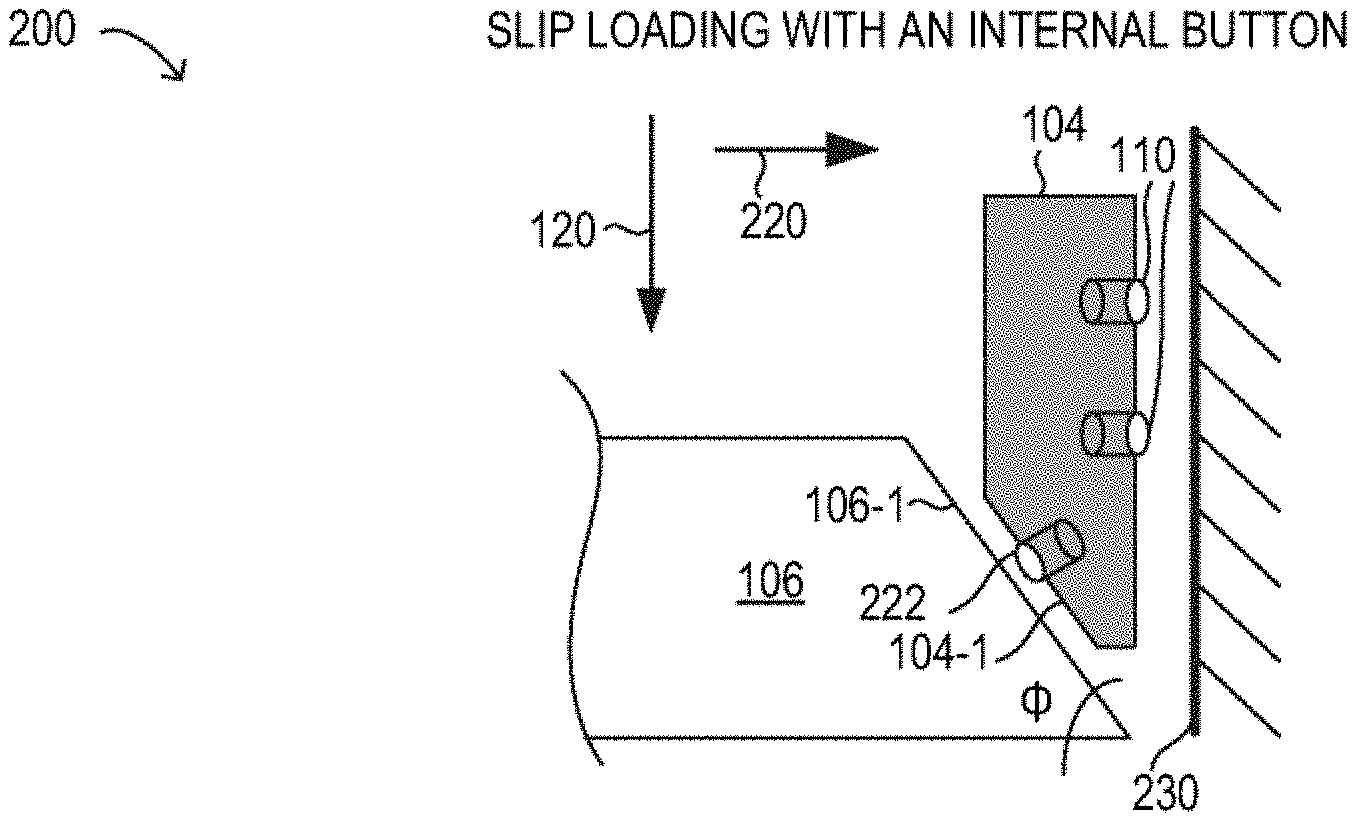
[0039] FIG. 2 is a partial sectional view of slip loading with an internal button;
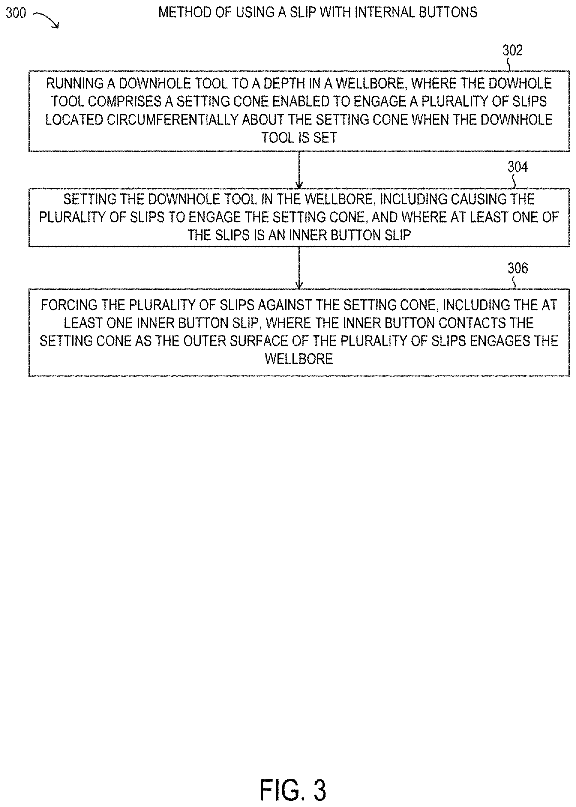
[0040] FIG. 3 is a flow chart of a method using a slip with internal buttons;
[0041] FIG. 4A is a depiction of a frac plug having slips with internal buttons; and
[0042] FIG. 4B is a depiction of a frac plug having slips with internal buttons.
DESCRIPTION OF PARTICULAR EMBODIMENT(S)
[0043] In the following description, details are set forth by way of example to facilitate discussion of the disclosed subject matter. It should be apparent to a person of ordinary skill in the field, however, that the disclosed embodiments are exemplary and not exhaustive of all possible embodiments.
[0044] Throughout this disclosure, a hyphenated form of a reference numeral refers to a specific instance of an element and the un-hyphenated form of the reference numeral refers to the element generically or collectively. Thus, as an example (not shown in the drawings), device "12-1" refers to an instance of a device class, which may be referred to collectively as devices "12" and any one of which may be referred to generically as a device "12". In the figures and the description, like numerals are intended to represent like elements.
[0045] As noted above, slips are parts in downhole tools, such as packers, bridge plugs, and frac plugs, among others, that may be used for anchoring against a surface of a wellbore, typically by using a cone-shaped member to force the slips against the surface of a wellbore. The gripping force that the slips are capable of exerting can be a key factor in the design and implementation of the downhole tool. The frictional performance of the slip may be determinative for the strength of the seal formed by the downhole tool and the amount of pressure that the seal and the downhole tool can withstand. Seals and downhole tools that can withstand higher pressures or higher flow rates are desirable because they enable wider ranges of operating conditions for well operators. Accordingly, slips having hard external or exterior buttons, such as ceramic buttons, have been used to improve the coefficient of friction between the slip and the casing, thereby improving the frictional force applied by the slip.
[0046] As will be disclosed in further detail herein, a slip with internal buttons for use in a downhole assembly, such as in a downhole tool, is disclosed. The slip with internal buttons for use in a downhole assembly disclosed herein may enable an increased frictional force between the slip and a setting cone in a downhole tool, for example. Accordingly, the slip with internal buttons for use in a downhole assembly disclosed herein may enable an improved design for a downhole tool, such as by using a single setting cone with slips in the downhole tool instead of a pair of setting cones with respective pairs of slips, which may enable a substantially more compact downhole tool for a given frictional force, which is desirable. The slip with internal buttons for use in a downhole assembly disclosed herein may be implemented using a variety of materials for the slip body and or the internal buttons, as disclosed herein.
[0047] Referring now to the drawings, FIG. 1 shows a portion of a frac plug 100 having slips 104. FIG. 1 is a schematic diagram for descriptive purposes and is not drawn to scale or perspective. In FIG. 1, the depicted portion of frac plug 100 includes a setting cone 106 (or simply, cone 106). In particular embodiments, cone 106 may have a frustoconical shape. Frac plug 100 may operate to plug a wellbore, such as a cased wellbore having a casing diameter of 3.5 inches, 4 inches, 4.5 inches, or 5.5 inches, among other casing diameters. It will be understood that frac plug 100 may include other elements, such as additional sets of setting cones and corresponding slips, in various embodiments. For example in some embodiments, frac plug 100 may include an elastomeric member that expands to seal the casing diameter when frac plug 100 is set in place. Frac plug 100 may be set in place by compressing frac plug 100, such that slips 104 are engaged to firmly hold frac plug 100 in a particular location in a corresponding wellbore, such as within a casing of the wellbore. The frictional force of slips 104 pressing against the interior surface of the wellbore (or the casing) holds frac plug 100 in place in the set or "plugged" condition. Accordingly, the force that maintains the plug 100 in the set or plugged condition is achieved by virtue of the material strength of slips 104 as well as a frictional force between slips 104 and cone 106.
[0048] As shown in FIG. 1, in frac plug 100, cone 106 is located adjacent to slips 104, which may be a plurality of parts arranged axially next to each other and may be bound together with at least one ring clamp (not shown) prior to downhole introduction and engagement. When slips 104 are forced against cone 106 in the direction given by arrow 120 (i.e., the frac plug is compressed), cone 106 works with appreciable force against an inner surface of each individual composite slip 104, which may cause a ring clamp to fail and to release slips 104. Because slips 104 are nonetheless contained in the downhole setting, slips 104 are forced outward to press against the wellbore or the casing. Also shown are ceramic buttons 110, which may be embedded at an outer surface of slips 104 to provide increased friction and hardness to improve the securing of frac plug 100 by slips 104. As will be described in further detail, slips 104 may have internal (or inner) buttons (not visible in FIG. 1, see FIGS. 2 and 4B), as disclosed herein, that provide increased friction and hardness to improve the engagement of cone 106 against an internal (or inner) surface of slips 104.
[0049] Although a frac plug 100 is shown incorporating slips 104, it will be understood that other types of downhole tools, such as bridge plugs, packers or other sealing devices, may incorporate slips 104 having internal buttons.
[0050] Referring now to FIG. 2, a slip loading 200 with an internal button 222 is shown as a cross-sectional schematic diagram. FIG. 2 is a schematic diagram for descriptive purposes and is not drawn to scale or perspective. In FIG. 2, the operation of slip 104 being forced against cone 106 in direction given by arrow 120 is illustrated at one side of a casing 230. As a result, as the slips move in direction 120, cone 106 engages slip 104 with appreciable force and causes slip 104 to be forced towards casing 230 in direction 220. At an outer surface of slip 104, an external button 110 may be used to improve engagement of slip 104 with casing 230, such as by increasing friction or by mechanical deformation (not shown) of casing 230. Thus, as cone 106 is engaged when frac plug 100 is set, a cone surface 106-1 may engage with an angled surface 104-1 of slip 104, which applies force to slip 104 in direction 220.
[0051] Also shown in FIG. 2 is internal button 222, located at angled surface 104-1 of slip 104. Angled surface 104-1 may represent an internal or inner surface of slip 104. In particular, angled surface 104-1 may be parallel to cone surface 106-1 that is designed to engage slip 104 at angled surface 104-1. It is noted that an angle of angled surface 104-1 may correspond to a cone angle .phi. shown in FIG. 2. In particular, internal button 222 is visible in a location at angled surface 104-1 for engagement by cone surface 106-1. Accordingly, internal button 222 may improve the setting force that is applied to slip 104, such as by increasing friction between slip 104 and cone 106. Because internal button 222 may be formed from a material that has a higher coefficient of friction than angled surface 104-1 when in contact with setting cone 106, such as a hard metal, a ceramic, a glass, a composite of non-metallic and metallic materials, or another composite material (such as a fiber-reinforced ceramic), among others, internal button 222 may enable an improved setting of the downhole tool or assembly, and may improve stability in operation, because of the increased frictional three that results from internal button 222. As a result of this increased frictional force enabled by internal button 222 at angled surface 104-1, the ability of slip 104 to hold the downhole tool or assembly in place in operation may be improved, including the ability to stay in place at higher pressures or at higher flowrates in the wellbore. For example, the downhole tool or assembly may be enabled to withstand high pressure, such as pressures of up to 8 kpsi (about 55 MPa), up to 10 kpsi (about 69 MPa), or up to 12 kpsi (about 83 MPa) within the wellbore. Furthermore, the downhole tool or assembly may be enabled to withstand high flow rates during production, such as such as up to 80 million standard cubic feet per day (MMSCFD) of gas or up to 4,000 barrels of oil per day (BOPD).
[0052] In some instances, internal button 222 may accordingly enable a more compact design in a given downhole tool or assembly, such as by enabling the use of a single set of cone 106/slips 104 instead of a plurality of sets, for example, to achieve the same downhole slip performance (see also FIGS. 4A and 4B).
[0053] As shown, external buttons 110 and internal button 222 may be formed as cylindrically shaped parts that are mounted in corresponding holes formed in slip 104. Additionally, the exposed surfaces of external buttons 110 or internal button 222 or both may be non-parallel with their respective engaging surfaces, such that external buttons 110 or internal button 222 have an edge that can bite in the respective engaging surface when set to further increase frictional force. It is noted that in various embodiments, internal button 222 may cause at least some plastic deformation in cone 106 when set, such as an indentation that corresponds to the shape of internal button 222 and helps to hold internal button 222, and also slip 104, in place when set. In some embodiments, cone 106 may be formed from a metal, such as steel, while internal button 222 may be formed from a hard material, such as a ceramic. It is noted that a body of slip 104 may be formed from any of various materials, including metals or rubbers, resin, epoxy, or other polymers. In particular, the body of slip 104 may be a composite material having a matrix phase as noted with an inclusion phase that may include various inclusions, such as fibers, filaments, and particles, or various combinations thereof.
[0054] In certain embodiments, slip 104 may be made using a filament-reinforced composite material, such as an epoxy with glass fiber filaments, among other types of composite matrix and inclusion combinations. In particular embodiments, the glass fiber is wound as a continuous filament on a mandrel from which individual parts for slip 104 may be cut. One example of a filament-reinforced slip part is disclosed in U.S. patent application Ser. No. 15/981,592 titled "Filament Reinforced Composite Material with Load-Aligned Filament Windings" filed on May 16, 2018, which is hereby incorporated by reference.
[0055] Referring now to FIG. 3, a flow chart of selected elements of an embodiment of a method 300 of using a slip with internal buttons, as disclosed herein. It is noted that certain operations described in method 300 may be optional or may be rearranged in different embodiments. In various embodiments, method 300 may be performed for various types of downhole tools, as described herein.
[0056] Method 300 may begin at step 302 by running a downhole tool to a depth in a wellbore, where the downhole tool comprises a setting cone enabled to engage a plurality of slips located circumferentially about the setting cone when the downhole tool is set. At step 304, the downhole tool is set in the wellbore, including causing the plurality of slips to engage the setting cone, and where at least one of the slips is an inner button slip. At step 306, the plurality of slips are forced against the setting cone, including the at least one inner button slip, where the inner button contacts the setting cone as the outer surface of the plurality of slips engages the wellbore.
[0057] Referring now to FIGS. 4A and 4B, a frac plug 400 having slips 404 is depicted in an external view and a sectional view, respectively. FIGS. 4A and 4B are schematic diagrams for descriptive purposes and are not drawn to scale or perspective. In FIG. 4A, frac plug 400 is shown as a compact tool exhibiting a relatively low ratio of tool length to tool diameter and includes a frustoconical member 406, which may be similar to or analogous to cone 106 described above with respect to FIGS. 1 and 2. Although frustoconical member 406 is depicted in the drawings having relatively smooth surfaces, it is noted that in different embodiments, different surface roughness, surface geometries, or surface texture may be used, such as in conjunction with a given design or material choice of slips 404, for example. Frac plug 400 may operate to plug a wellbore, such as a cased wellbore having a casing diameter of 3.5 inches, 4 inches, 4.5 inches, or 5.5 inches, among other casing diameters. Frac plug 400 may be set in place by compressing frac plug 400, such that slips 404 are engaged to firmly hold frac plug 400 in a particular location in a corresponding wellbore, such as within a casing of the wellbore. Frac plug 400 may be compressed for setting in place by forcing slips 404 against frustoconical member 406 in a direction given by arrow 420. The frictional force of slips 404 pressing against the interior surface of the wellbore (or the casing) holds frac plug 400 in place in the set or "plugged" condition. Accordingly, the force that maintains frac plug 400 in the set or plugged condition is achieved by virtue of the material strength of slips 404, as well as the friction between slips 404 and frustoconical member 406. Also visible in FIGS. 4A and 4B are external buttons 410, which are enabled to engage the casing when frac plug 400 is set.
[0058] In FIG. 4A, a sectional line on frac plug 400-1 indicates a sectional view 400-2 shown in FIG. 4B. In FIG. 4B showing the sectional view 400-2, internal (or inner) buttons 422 and external buttons 410 are visible. Specifically, internal buttons 422 are shown embedded within slip 404 and protrude from slip 404. Also visible in FIG. 4B is a slight non-parallel surface of internal buttons 422, resulting in an edge to cylindrically shaped internal buttons 422 that is enabled to engage with frustoconical member 406 when frac plug 400 is set (not shown), such as by biting into or otherwise deforming at least a portion of frustoconical member 406.
[0059] The non-parallel surface of internal buttons 422 or external buttons 410 may be realized using different methods. As shown in FIG. 4B, internal buttons 422 are regular cylinders that are embedded in a hole that is drilled at a non-perpendicular angle to an inner surface 404-1 of slip 404 (see also inner surface 104-1 in FIG. 1). In other embodiments, internal buttons 422 or external buttons 410 may be cylindrical parts that are cut obliquely with a non-perpendicular surface at least one end, while the holes drilled in slip 404 are drilled perpendicular to inner surface 404-1. It is noted that in certain implementations, external buttons 422 or internal buttons 410 may be non-cylindrical in shape, such as having shapes of triangular prisms, square prisms, rectangular prisms, or other polygonal prisms (not shown).
[0060] In this manner, internal buttons 422 may increase the frictional force by which slip 404 is held in place by frustoconical member 406 when frac plug 400 is set, which may enable the relatively low ratio of tool length to tool diameter, such as by allowing frac plug 400 to have a single frustoconical member 406, instead of a plurality of cones and a respective plurality of sets of slips.
[0061] The above disclosed subject matter is to be considered illustrative, and not restrictive, and the appended claims are intended to include all such modifications, enhancements, and other embodiments thereof which fall within the true spirit and scope of the present disclosure.
* * * * *
D00000
D00001
D00002
D00003
XML
uspto.report is an independent third-party trademark research tool that is not affiliated, endorsed, or sponsored by the United States Patent and Trademark Office (USPTO) or any other governmental organization. The information provided by uspto.report is based on publicly available data at the time of writing and is intended for informational purposes only.
While we strive to provide accurate and up-to-date information, we do not guarantee the accuracy, completeness, reliability, or suitability of the information displayed on this site. The use of this site is at your own risk. Any reliance you place on such information is therefore strictly at your own risk.
All official trademark data, including owner information, should be verified by visiting the official USPTO website at www.uspto.gov. This site is not intended to replace professional legal advice and should not be used as a substitute for consulting with a legal professional who is knowledgeable about trademark law.