Bag Storage Case
TSUCHIDA; Kengo ; et al.
U.S. patent application number 16/814793 was filed with the patent office on 2020-12-17 for bag storage case. The applicant listed for this patent is TOSHIBA TEC KABUSHIKI KAISHA. Invention is credited to Hiroki SAKAMOTO, Kengo TSUCHIDA.
| Application Number | 20200391932 16/814793 |
| Document ID | / |
| Family ID | 1000004732960 |
| Filed Date | 2020-12-17 |


| United States Patent Application | 20200391932 |
| Kind Code | A1 |
| TSUCHIDA; Kengo ; et al. | December 17, 2020 |
BAG STORAGE CASE
Abstract
A bag storage case includes a holding part and a wall. The holding part holds a plurality of stacked bags. The wall has a take-out opening in a width direction of the plurality of stacked bags and a first width that is smaller than a second width of the plurality of stacked bags and a middle of the take-out opening is larger than opposite ends of the take-out opening in a stacking direction of the plurality of stacked bags.
| Inventors: | TSUCHIDA; Kengo; (Izunokuni Shizuoka, JP) ; SAKAMOTO; Hiroki; (Izunokuni Shizuoka, JP) | ||||||||||
| Applicant: |
|
||||||||||
|---|---|---|---|---|---|---|---|---|---|---|---|
| Family ID: | 1000004732960 | ||||||||||
| Appl. No.: | 16/814793 | ||||||||||
| Filed: | March 10, 2020 |
| Current U.S. Class: | 1/1 |
| Current CPC Class: | B65D 83/0817 20130101; B65D 33/001 20130101 |
| International Class: | B65D 83/08 20060101 B65D083/08; B65D 33/00 20060101 B65D033/00 |
Foreign Application Data
| Date | Code | Application Number |
|---|---|---|
| Jun 14, 2019 | JP | 2019-111570 |
Claims
1. A bag storage case comprising: a holding part for holding a plurality of stacked bags; a wall having a take-out opening, the take-out opening extending in a width direction of the plurality of stacked bags and having a first width in the width direction that is smaller than a second width of the plurality of stacked bags and a middle of the take-out opening is larger than opposing ends of the take-out opening in a stacking direction of the plurality of stacked bags.
2. The bag storage case according to claim 1, wherein the wall, side walls on either side of the wall, an upper wall on an upper side of the wall, and a bottom wall on a bottom side of the wall form a partially enclosed holding area for the plurality of stacked bags.
3. The bag storage case according to claim 2, wherein when the second width of the plurality of stacked bags is Fs and the first width of the take-out opening is Tw, Tw=0.68Fs+2.2.
4. The bag storage case according to claim 1, wherein when held by the holding part, the plurality of stacked bags are folded, and the take-out opening faces a folded portion of the plurality of stacked and folded bags held by the holding part.
5. The bag storage case according to claim 1, further comprising an adjusting member configured to adjust a position of the plurality of stacked bags held by the holding part with respect to the take-out opening.
6. A bag storage case, comprising: a housing including a pair of first walls, a pair of second walls, and a third wall, the pair of first walls and the pair of second walls forming a parallelepiped shape and the third wall covering one of two openings formed by the pair of first walls and the pair of second walls, the third wall having a take-out opening extending in a fist direction and having a first width, the take-out opening having a middle portion that is larger than opposite end portions of the take-out opening; and a holder configured to hold a plurality of stacked and folded bags, the plurality of stacked and folded bags having a second width that is larger than the first width of the take-out opening, the holder being insertable into the housing through an opening opposite the third wall so that a folded portion of the plurality of stacked and folded bags is opposite the take-out opening.
7. The bag storage case according to claim 6, wherein the third wall comprises a first inclined part and a second inclined part, the take-out opening being formed in the first inclined part.
8. The bag storage case according to claim 6, wherein the holder comprises a tray and a holding part, the holding part including a shaft that is configured to be received in the folded portion of the plurality of stacked and folded bags.
9. The bag storage case according to claim 8, wherein the holding part includes a support plate configured to support a first side of the plurality of stacked and folded bags.
10. The bag storage case according to claim 9, wherein the support plate is at an angle to the pair of first walls when the holder is inserted into the housing.
11. The bag storage case of claim 8, wherein the holding part includes an adjusting member configured to bias the folded portion toward the take-out opening.
12. The bag storage case according to claim 9, wherein the tray includes a hanging part configured to a second side of the plurality of stacked and folded bags.
13. The bag storage case according to claim 12, wherein the hanging part includes a cylindrical part and a flange at an end of the cylindrical part, the cylindrical part being configured to inserted into a hole in the plurality of stacked and folded bags, and the flange having a diameter larger than a diameter of the hole.
14. The bag storage case according to claim 6, wherein the holder further comprises a guide part comprising a pair of projections that are configured to engage opposing sides of a bag from the plurality of stacked and folded bags being withdrawn through the take-out opening.
15. The bag storage case according to claim 6, wherein the first width of the take-out opening is a function of the second width of the plurality of stacked and folded bags.
16. The bag storage case according to claim 15, wherein the function is a linear function.
17. The bag storage case according to claim 16, wherein the second width of the plurality of stacked and folded bags is Fs and the fist width of the take-out opening is Tw and Tw=0.68Fs+2.2.
18. The bag storage case according to claim 6, wherein the opposite end portion of the take-out opening are curved.
19. A bag storage system, comprising: a plurality of bag storage cases according to claim 6.
20. The bag storage system according to claim 19, wherein at least one take-out opening of the plurality of bag storage cases has a different first width from at least one other bag storage case.
Description
CROSS-REFERENCE TO RELATED APPLICATIONS
[0001] This application is based upon and claims the benefit of priority from Japanese Patent Application No. 2019-111570, filed on Jun. 14, 2019, the entire contents of which are incorporated herein by reference.
FIELD
[0002] Embodiments described herein relate to a bag storage case.
BACKGROUND
[0003] As a device for performing settlement processing by a customer, a self-checkout device and a settlement device are known. For example, the self-checkout device is a device for reading information of a commodity by the customer himself/herself to perform settlement. For example, the settlement apparatus is an apparatus for allowing the customer to perform only the settlement.
[0004] The commodity which has been subjected to the settlement processing by using such a settlement apparatus is placed into the bag by the customer.
[0005] Such a bag is called a register bag, and for example, a clerk who is in charge provides the register bag to the customer.
[0006] In addition, in recent years, there has been a case where the customer brings a bag, and the bag is suspended around the settlement apparatus.
[0007] In view of hygiene, there has been known a technique for accommodating a plurality of bags stacked on a drawer shelf such as a holder, and a technique for folding a plurality of stacked bags to be accommodated in a holder. When the bag is contained in such a drawer shelf or holder, it is required that the bag be visually recognizable so that the size and remaining amount of the bag can be known. However, when the take-out opening for taking out the contained bag is large, a plurality of bags may be taken out at a time, and when the take-out opening is small, there is a problem that it is difficult to take out the bag.
BRIEF DESCRIPTION OF THE DRAWINGS
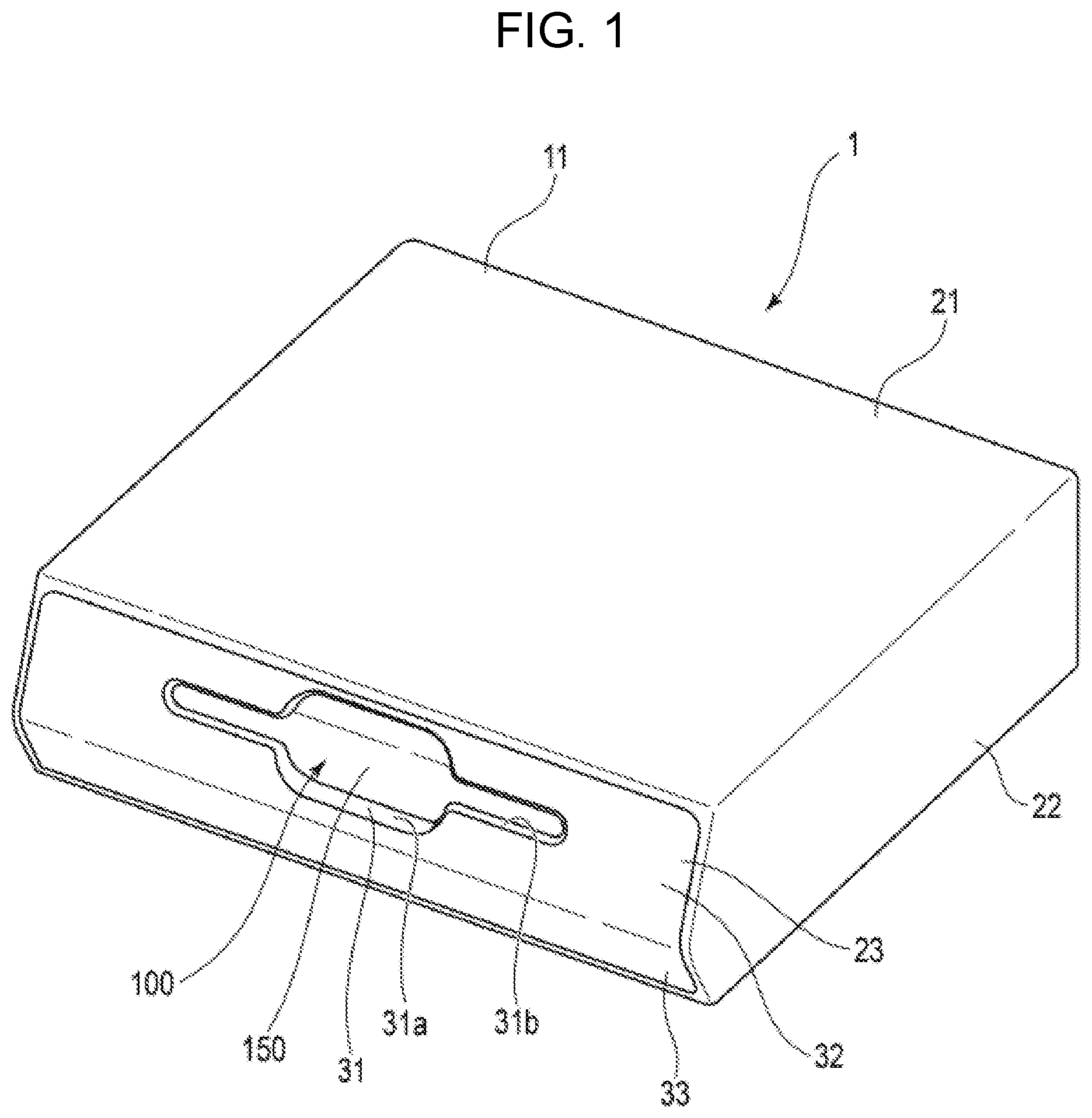
[0008] FIG. 1 is a front perspective view showing a configuration of a bag storage case according to a first embodiment;
[0009] FIG. 2 is a rear perspective view showing a configuration of the bag storage case;
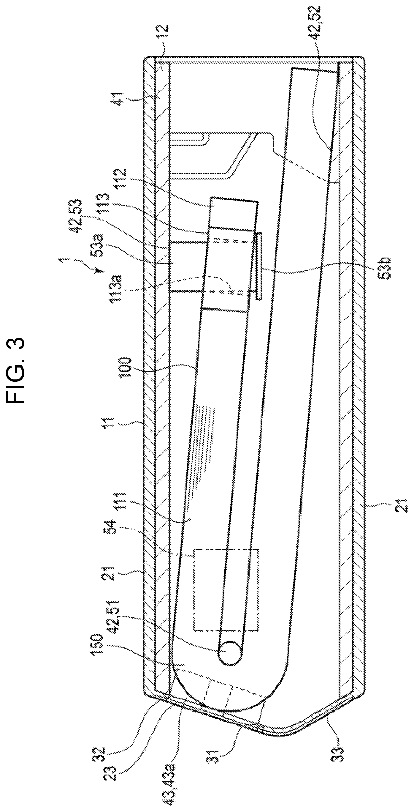
[0010] FIG. 3 is a cross-sectional view showing a configuration of the bag storage case;
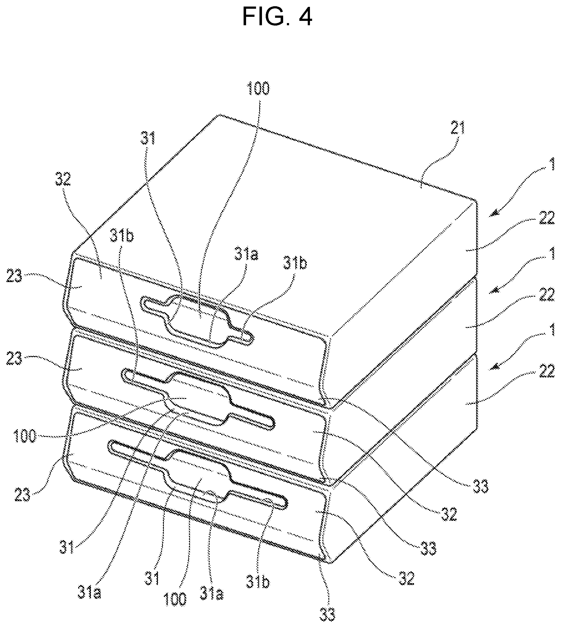
[0011] FIG. 4 is a front perspective view showing bag storage cases that are stacked;
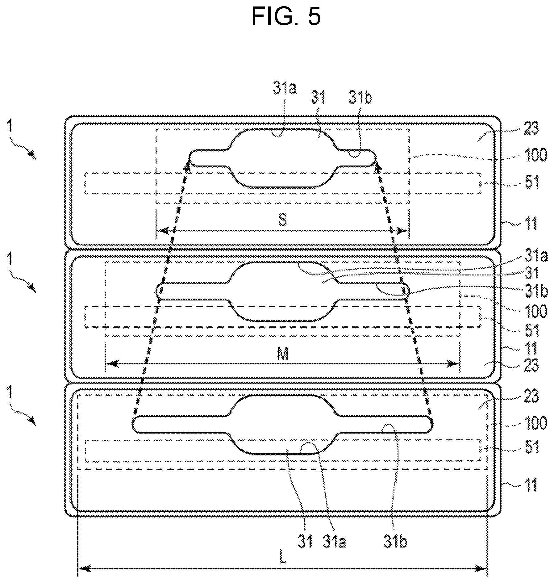
[0012] FIG. 5 is a front view showing bag storage cases that are stacked;
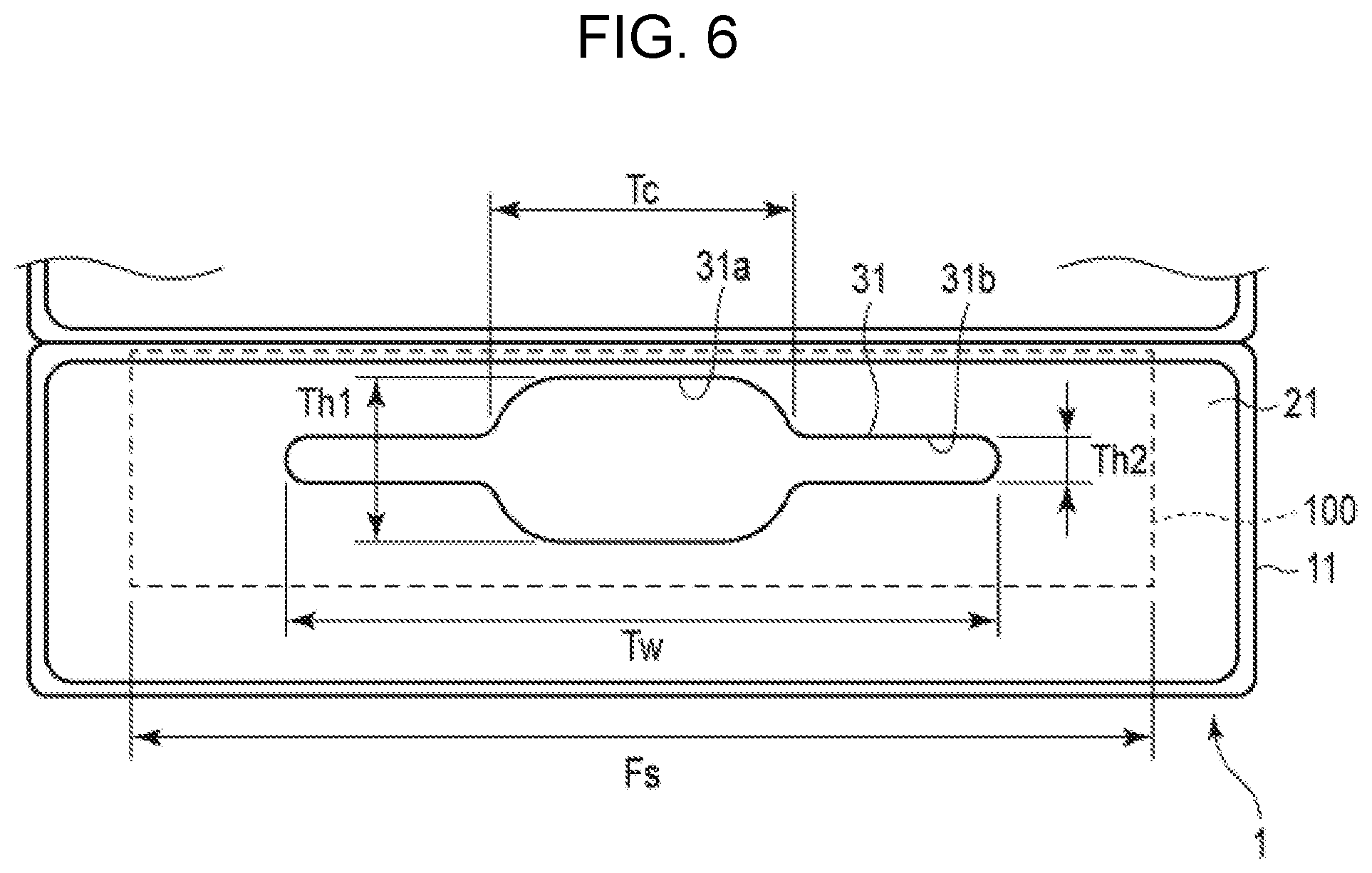
[0013] FIG. 6 is a view showing the bag storage case from the front;
[0014] FIG. 7 is a view showing a relationship between the take-out opening and the bag of the bag storage case; and
[0015] FIG. 8 is a front perspective view showing a configuration of a bag storage case according to another embodiment.
DETAILED DESCRIPTION
[0016] In general, according to one embodiment, the bag storage case includes a holding part and a wall. The holding part holds a plurality of stacked bags. The wall has a take-out opening, the take-out opening extends in a width direction of the plurality of stacked bags and has a first width in the width direction that is smaller than a second width of the plurality of stacked bags and a middle of the take-out opening is larger than opposite ends of the take-out opening in a stacking direction of the plurality of stacked bags.
[0017] Hereinafter, the bag storage case 1 according to the first embodiment will be described with reference to FIGS.
[0018] 1 to 6. FIG. 1 is a perspective view showing the configuration of the bag storage case 1 according to the first embodiment from the front side. FIG. 2 is a perspective view showing the configuration of the bag storage case 1 from the back side. FIG. 3 is a sectional view showing the configuration of the bag storage case 1. FIG. 4 is a perspective view showing bag storage cases 1 that are stacked. FIG. 5 is a front view showing bag storage cases 1 that are stacked. FIG. 6 is a view showing the structure of the bag storage case 1 from the front side. FIG. 7 is a view showing a relationship between the width Tw of the take-out opening 31 of the bag storage case 1 and the width Fs of the bag 100.
[0019] As shown in FIGS. 1 to 3, the bag storage case 1 includes a housing 11 and a holder 12.
[0020] The bag storage case 1 accommodates a plurality of bags 100 in the housing 11 in a state in which the plurality of bags 100 are stacked and held by the holder 12. The plurality of bags 100 are held so as to be able to be taken out in the state in which the plurality of bags 100 are stacked by the holder 12.
[0021] As shown in FIGS. 4 and 5, for example, the bag storage case 1 is formed so as to be stackable with additional storage cases.
[0022] In the first embodiment, the bag 100 is a so-called "register bag". The bag 100 includes a main part 111, a pair of handles 112, and a hung part 113. One end of the main part 111 is closed, and the other end is open. The closed end of the main part 111 forms the bottom of the bag 100. The extending direction of the closed end edge forming the bottom of the bag 100 will be described below with reference to the width direction of the bag 100.
[0023] The pair of handles 112 are integrally formed on the other end of the main part 111 on an opening of the main part 111 of the bag 100. The hung part 113 is provided at one end of the opening of the main part 111 and between the pair of handles 112. The hung part 113 is formed, for example, with a hole 113a.
[0024] The hung part 113 is integrally provided with the main part 111 so as to be separable from the main part 111. As a specific example, a perforation or the like is formed at the boundary between the main part 111 and the hung part 113 to separate the hung part 113 from the main part 111.
[0025] For example, a plurality of bags having different widths are used as the bags 100. As a specific example, three types of bags 100 having an L-size having a large width, an M-size having a middle width size, and an S-size having a small width are used. For example, the L-size bag 100 has a width of 320 mm, the M-size bag 100 has a width of 260 mm, and the S-size bag 100 has a width of 145 mm.
[0026] For example, as shown in FIG. 3, a plurality of such bags 100 are stacked and folded at a folded portion 150 in the main part 111. Then the folded portion 150 is held on a shaft 51 in the holder 12, and the plurality of stacked and folded bags 100 are accommodated in the housing 11.
[0027] As shown in FIG. 1 to FIG. 3, the housing 11 includes a pair of first walls 21, a pair of second walls 22, and a third wall 23. The housing 11 is formed in a rectangular box shape in which one surface is opened by, for example, a pair of first walls 21, a pair of second walls 22, and a third wall 23.
[0028] The pair of first walls 21 are opposed to each other at intervals in which a plurality of stacked and folded bags 100 are disposed. That is, the pair of first walls 21 are opposed to each other so as to accommodate a plurality of stacked and folded bags 100. More specifically, the pair of first walls 21 are spaced apart from each other at intervals in which the holder 12 for holding the stacked and folded bags 100 can be disposed.
[0029] The pair of first walls 21 are opposed to the stacked and folded bags 100 in the stacking direction of the plurality of stacked and folded bags 100. In other words, the pair of first walls 21 are opposed to the main surface of the main part 111 of the bag 100. For example, the bag storage case 1 is placed on an installation surface such that one of the pair of first walls 21 is positioned downward. The pair of first walls 21 are opposed to each other in the height direction to form a bottom wall and a top wall of the bag storage case 1.
[0030] The pair of second walls 22 are continuous with the pair of first walls 21. The pair of second walls 22 are opposed to each other in the width direction of the accommodated stacked and folded bags 100. The pair of second walls 22 are spaced apart from each other a distance larger than the width of the stacked and folded bags 100 so that the plurality of stacked and folded bags 100 can be disposed. For example, the pair of first walls 21 constitute a pair of side walls of the bag storage case 1.
[0031] The third wall 23 has a take-out opening 31 in a part thereof. The third wall 23 is continuous with the pair of first walls 21 and the pair of second walls 22. The third wall 23 includes, for example, a first inclined part 32 inclined to the opposing direction of the pair of first walls 21, and a second inclined part 33 inclined with respect to the opposing direction of the pair of first walls 21 and inclined in a direction different from the direction of the first inclined part 32. Hereinafter, the "opposite direction of the pair of first walls 21" will be described as the "first direction". When the pair of first walls 21 constitute a bottom wall and a top wall, the first direction is the lateral, or vertical, direction.
[0032] As a specific example, the take-out opening 31 is provided in the first inclined part 32. The take-out opening 31 is opposed to the folded portion 150 of the plurality of stacked and folded bags 100 accommodated in the housing 11.
[0033] The take-out opening 31 extends along the opposite direction of the pair of second walls 22. Hereinafter, the "opposite direction of the pair of second walls 22" will be described as the "second direction". When the pair of first walls 21 constitutes a bottom wall and a top wall, the second direction is the longitudinal, or horizontal, direction. The width in the longitudinal direction of the take-out opening 31 is smaller than the width of the bag 100. Further, the center, or middle, of the take-out opening 31 is larger than both end sides of the take-out opening 31 in the first (i.e. vertical) direction. That is, the take-out opening 31 has a wide center or middle and narrow ends in the first direction. That is, the width of the take-out opening 31 in the lateral (i.e. vertical) direction is different between the center or middle and both end sides, and the width in the center or middle is larger than the width on both end sides. Further, the take-out opening 31 is set to have a constant width in the first direction in the center or middle and a constant width in the first direction on both end sides. Moreover, the take-out opening 31 is formed to have a curved corner portion.
[0034] As shown in FIG. 4, the length of the take-out opening 31 in the second direction, that is the length in the longitudinal direction, is set by the width of the bag 100. As a specific example, as shown in FIG. 4, the take-out opening 31 is formed of a first opening 31a provided in the center or middle and a second opening 31b provided on both end sides in the second direction of the first opening 31a and continuing to the center or middle in the first direction.
[0035] For example, the width of the first opening 31a in the second direction is constant regardless of the width of the bag 100.
[0036] The width of the second opening 31b in the second direction is smaller than the width of the bag 100, and is set as appropriate based on the width of the bag 100. For example, the width of the second opening 31b in the second direction is set as a function of the width of the bag 100.
[0037] The first inclined part 32 is continuous with the first wall 21 forming the top wall and the second inclined part 33 in the first direction.
[0038] The second inclined part 33 is continuous with the first wall 21 forming the bottom wall and the first inclined part 32 in the first direction.
[0039] That is, for example, the first inclined part 32 is positioned above the second inclined part 33.
[0040] The first inclined part 32 and the second inclined part 33 are inclined in a direction away from the first wall 21 toward a center side in the first direction from the first wall 21 side.
[0041] In other words, the first inclined part 32 and the second inclined part 33 are continuous at the center side in the first direction, and the continuous portions of the first inclined part 32 and the second inclined part 33 are protruded from the outside of the housing 11.
[0042] In other words, the third wall 23 is formed in a shape that is chamfered by the pair of first walls 21, the first inclined part 32, and the second inclined part 33.
[0043] Such a housing 11 is formed, for example, by integrally molding a pair of first walls 21 and a pair of second walls 22 in a rectangular cylindrical or parallelepiped shape, and by covering one of the openings formed by the pair of first walls 21 and the pair of second walls 22 with the third wall 23. The front side of the case 11 is formed by the third wall 23, and the rear side is formed by the opening on the opposite side of the third wall 23.
[0044] Note that the housing 11 may be configured by assembling a panel that forms a pair of first walls 21, a pair of second walls 22, and a third wall 23 on a frame having a rectangular parallelepiped shape.
[0045] Further, the housing 11 may be formed by integrally molding a pair of first walls 21, a pair of second walls 22, and a third wall 23.
[0046] As shown in FIGS. 1 to 3, the holder 12 includes, for example, a tray 41, a holding part 42, and a guide part 43.
[0047] The tray 41 is formed in a rectangular cylindrical or parallelepiped shape which is in contact with the pair of first walls 21 and the pair of second walls 22.
[0048] For example, the tray 41 is configured such that a wall portion of the tray 41 that forms an upper wall of the tray 41 is opposed to the first wall 21 and can be opened and closed.
[0049] Note that the tray 41 may not have the wall portion opposed to the first wall 21 forming the upper wall, for example as shown in FIG. 8.
[0050] The tray 41 has a width equal to or slightly larger than the width of the bag 100, between inner surfaces of a pair of walls opposed to the pair of second walls 22.
[0051] The tray 41 is insertable into the opening on the back side of the housing 11 and is removable therefrom, so that the tray 41 can be attached to and detached from the housing 11.
[0052] The tray 41 accommodates the plurality of stacked and folded bags 100 held by the holding part 42, and the front side and the back side of the tray 41 are open so that the plurality of stacked and folded bags 100 can be inserted and taken out.
[0053] The holding part 42 is provided, for example, in the tray 41.
[0054] As shown in FIG. 3, the holding part 42 includes a shaft 51 for supporting the folded portion 150 of the plurality of stacked and folded bags 100, a support plate 52 for supporting one end of the plurality of stacked and folded bags 100, a hanging part 53 for hooking and holding the hung parts 113 of the stacked and folded bags 100, and an adjusting member 54 for urging the shaft 51 in one direction.
[0055] The shaft 51 is disposed to face the take-out opening 31 of the third wall 23. The shaft 51 is supported by the tray 41. For example, the shaft 51 is supported on the tray 41 so as to be movable toward the take-out opening 31. The folded portion 150 of the plurality of stacked and folded bags 100 is wrapped around the shaft 51 and the shaft 51 supports the folded portion 150 from the inside.
[0056] The support plate 52 supports a bottom side of the plurality of stacked and folded bags 100. The support plate 52 is disposed at the rear opening in a state in which the tray 41 is disposed in the housing 11 and is disposed below the shaft 51. The support plate 52 is formed at a predetermined angle with respect to the main surface of the first wall 21 on which the top surface becomes a bottom plate. That is, as shown in FIG. 3, the support plate 52 supports a plurality of stacked and folded bags 100 with the shaft 51, thereby supporting the plurality of stacked and folded bags 100 at a predetermined angle with respect to the main surface of the first wall 21 serving as a bottom wall.
[0057] The hanging part 53 holds the hung parts 113 of the plurality of stacked and folded bags 100. For example, the hanging part 53 is provided on an upper wall of the tray 41. The hanging part 53 includes a cylindrical part 53a inserted into the hole 113a of the hung part 113, and a flange 53b having a diameter larger than the inner diameter of the hole 113a.
[0058] The hanging part 53 holds one end of the plurality of stacked and folded bags 100 by inserting the cylindrical part 53a into the hole 113a of the hung part 113 of the plurality of stacked and folded bags 100 and holding the hung part 113 of the stacked and folded bags 100 by the innermost layer of the flange 53b.
[0059] The hanging part 53 may be, for example, a hook inserted into the hole 113a of the hung part 113.
[0060] The adjusting member 54 is a biasing member that presses the shaft 51 in one direction toward the take-out opening 31.
[0061] The adjusting member 54 presses the shaft 51 toward the take-out opening 31 to keep the positional relationship between the bag 100 positioned in the outermost layer of the plurality of stacked and folded bags 100 and the take-out opening 31 constant even when the number of remaining bags of the plurality of stacked and folded bags 100 is reduced.
[0062] The adjusting member 54 may include, for example, a coil spring or the like which presses the shaft 51 toward the take-out opening 31.
[0063] In the holding part 42, the plurality of stacked and folded bags 100 are supported on the tray 41 by the shaft 51, the support plate 52, and the hanging part 53, and the positions of the bags to the take-out opening 31 are adjusted by an adjusting member 54.
[0064] The guide part 43 is provided on a leading end side in the insertion direction of the tray 41 from the shaft 51 of the tray 41.
[0065] The guide part 43 is disposed between the take-out opening 31 and the shaft 51 when the tray 41 is disposed in the housing 11.
[0066] The guide part 43 is composed of a pair of projections 43a arranged side by side in the width direction of the bag 100. For example, each of the pair of projections 43a extends from the width of the bag 100 to the width of the second opening 31b of the take-out opening 31, and when a bag 100 is taken out from the take-out opening 31, both ends of the bag 100 in the width direction engage and are guided to the second opening 31b of the take-out opening 31 by the projections 43a.
[0067] Next, an example of the dimensional relationship between the take-out opening 31 of the bag storage case 1 and the bag 100 configured as described above will be described with reference to FIG. 6.
[0068] As shown in FIG. 6, the width (bag width) of the bag 100 is assumed to be Fs.
[0069] The width of the first opening 31a in the second direction is set to Tc, and the width of the first opening 31a in the first direction is set to Th1.
[0070] Further, as shown in FIG. 6, the width of the second opening 31b in the second direction is set to Tw, and the width of the second opening 31b in the first direction is set to Th2.
[0071] The dimension relation between the take-out opening 31 and the bag 100 is as follows.
Fs>Tw>Tc
Tw>Tc
Th1>Th2
[0072] Further, when the L, M and S-size bag 100 is used, the size of the first opening 31a is set to Tc.gtoreq.60 mm, and Th1.gtoreq.60 mm.
[0073] Also, for example, when the width (bag width) Fs (mm) of the bag 100 is set to the variable X, and the width Tw (mm) of the second opening 31b of the take-out opening 31 is set to the variable Y, the width Tw of the second opening 31b is determined by the linear function Y=0.68x+2.2 as shown in FIG. 7.
[0074] Note that the width Tw of the second opening 31b may be a width determined by a linear function or a width that is approximate to a width determined by a linear function.
[0075] As a specific example, in the case of an L-size bag 100 having a bag width Fs of 320 mm, the width Tw of the second opening 31b is set to 220 mm.
[0076] In the case of an M-size bag 100 having a width Fs of 260 mm, the width Tw of the second opening 31b is set to 180 mm.
[0077] In the case of an S-size bag 100 having a bag width Fs of 145 mm, the width Tw of the second opening 31b is set to 95 mm.
[0078] In the case of the bags 100 other than the L, M and S-sizes, it is set on the basis of the linear function.
[0079] For example, in the case of the bag 100 having the bag width Fs of 300 mm, the width Tw of the second opening 31b is set to 200 mm, and in the case of the bag 100 having the bag width Fs of 180 mm, the width Tw of the second opening 31b is set to 95 mm.
[0080] The bag storage case 1 configured as described above is arranged in such a manner that a plurality of bag storage cases 1 accommodating bags 100 having different sizes are arranged in the vertical direction, or arranged in the horizontal direction so that the take-out openings 31 face the same direction.
[0081] For example, FIG. 4 and FIG. 5 show an example in which three bag storage cases 1 are stacked in the vertical direction, the bag storage case 1 containing the L-size bag 100 is placed in the lower stage, the bag storage case 1 containing the M-size bag 100 is placed in the middle stage, and the bag storage case 1 containing S-size bag 100 is placed in the upper stage.
[0082] Each bag storage case 1 is arranged so that the take-out opening 31 is directed to the customer side.
[0083] For example, the bag storage case 1 may be provided in a self-checkout device or a settlement device, or may be installed in a place where a commodity purchased by using a self-checkout device or an settlement device is packaged.
[0084] For example, the bag storage case 1 is disposed below the customer's line of sight.
[0085] According to the bag storage case 1 configured as described above, by setting the width Tw of the take-out opening 31 to a proportional function of the width Fs of the bag 100, the take-out opening 31 can be made to have a suitable width to allow the bags 100 to be taken out one by one.
[0086] Further, since the width of the second opening 31b of the take-out opening 31 can be set to the optimum width according to the width of the bag 100, even when a bag 100 having a different bag width is used, the bag 100 can be taken out from the take-out opening 31.
[0087] In addition, the take-out opening 31 has a constant shape irrespective of the width of the bag 100 to perform the operation of taking out the bag 100 from the take-out opening 31.
[0088] In addition, the width Th1 in the first direction of the first opening 31a is set to be larger than the width Th2 in the same direction of the second opening 2b.
[0089] Therefore, the take-out opening 31 can suitably perform the removal operation of the bag 100 regardless of the bag width.
[0090] The bag storage case 1 is provided with a take-out opening 31 at a first inclined part 32 of the third wall 23.
[0091] Therefore, even when one bag storage case 1 is used, even when a plurality of bag storage cases 1 are stacked and arranged, the first inclined part 32 is positioned on the line of sight when the customer visually recognizes the bag storage case 1.
[0092] Therefore, the bag storage case 1 can improve the visibility of the take-out opening 31, so that the visibility of the bag 100 existing in the take-out opening 31 is improved.
[0093] In addition, the access to the bag 100 of the lower take-out opening 31 is improved, and even when the bag storage case 1 is stacked, the bag 100 can be easily taken out from the take-out opening 31.
[0094] As described above, according to the bag storage case 1 of the first embodiment, by optimizing the relationship between the size of the take-out opening 31 and the width of the bag 100, the bag 100 can be suitably taken out from the take-out opening 31.
[0095] Incidentally, the bag storage case 1 is not limited to the above embodiment.
[0096] In the example described above, the third wall 23 has the configuration having the first inclined part 32 and the second inclined part 33, but is not limited thereto.
[0097] For example, as shown in FIG. 8, the third wall 23 may not have the first inclined part 32 and the second inclined part 33, but may be formed in a planar shape orthogonal to the first wall 21 and the second wall 22.
[0098] Further, as shown in FIG. 8, the holder 12 may not have the upper wall of the tray 41 and the support plate 52.
[0099] In the example described above, the plurality of stacked and folded bags 100 are held by the holding part 42, and the take-out opening 31 is opposed to the folded portion 150 of the stacked and folded bags 100, but is not limited to this configuration as described above.
[0100] For example, the take-out opening 31 may be opposed to a portion other than the folded portion 150 of the stacked and folded bags 100, and the holding part 42 may be configured to hold a plurality of stacked bags 100 without being folded.
[0101] According to the bag storage case of at least one embodiment described above, the bag is suitably taken out from the take-out opening by optimizing the relation between the size of the take-out opening and the bag width of the bag.
[0102] While certain embodiments have been described, these embodiments have been presented by way of example only, and are not intended to limit the scope of the inventions.
[0103] Indeed, the novel embodiments described herein may be embodied in a variety of other forms; furthermore, various omissions, substitutions and changes in the form of the embodiments described herein may be made without departing from the spirit of the inventions.
[0104] These embodiments and variations thereof are included in the scope and spirit of the invention and are included within the scope of the appended claims and their equivalents.
* * * * *
D00000
D00001
D00002
D00003
D00004
D00005
D00006
D00007
D00008
XML
uspto.report is an independent third-party trademark research tool that is not affiliated, endorsed, or sponsored by the United States Patent and Trademark Office (USPTO) or any other governmental organization. The information provided by uspto.report is based on publicly available data at the time of writing and is intended for informational purposes only.
While we strive to provide accurate and up-to-date information, we do not guarantee the accuracy, completeness, reliability, or suitability of the information displayed on this site. The use of this site is at your own risk. Any reliance you place on such information is therefore strictly at your own risk.
All official trademark data, including owner information, should be verified by visiting the official USPTO website at www.uspto.gov. This site is not intended to replace professional legal advice and should not be used as a substitute for consulting with a legal professional who is knowledgeable about trademark law.