Drive Module For A Boat-like Buoyancy Body, And Buoyancy Body Equipped Therewith
Gertsch; Ulo
U.S. patent application number 16/762651 was filed with the patent office on 2020-12-17 for drive module for a boat-like buoyancy body, and buoyancy body equipped therewith. This patent application is currently assigned to Inventra AG. The applicant listed for this patent is INVENTRA AG. Invention is credited to Ulo Gertsch.
| Application Number | 20200391830 16/762651 |
| Document ID | / |
| Family ID | 1000005072842 |
| Filed Date | 2020-12-17 |

| United States Patent Application | 20200391830 |
| Kind Code | A1 |
| Gertsch; Ulo | December 17, 2020 |
DRIVE MODULE FOR A BOAT-LIKE BUOYANCY BODY, AND BUOYANCY BODY EQUIPPED THEREWITH
Abstract
The drive module buoyancy body is either made as a solid material, inflatable or as a hollow body with inflatable air chambers inside, which includes a seat and a shaft mounted in a front portion and extending in a direction transverse to the longitudinal direction of the buoyancy body. Paddle wheels are mounted at the ends of the shaft. A profile is articulated to the shaft in its center so as to be able to pivot about its lower end region, which profile extends upwards from the shaft and in which a crankshaft with a drive wheel is mounted at the upper end region of the profile. The cranks of the crankshaft can be optionally equipped with pedals for a foot drive or crank handles for a hand drive. By driving the cranks, the paddle wheels are driven by a roller chain or a toothed belt, the profile (7) being able to be engaged in a pivoted position for foot drive and being able to be engaged in a position different therefrom for manual drive.
| Inventors: | Gertsch; Ulo; (Steffisburg, CH) | ||||||||||
| Applicant: |
|
||||||||||
|---|---|---|---|---|---|---|---|---|---|---|---|
| Assignee: | Inventra AG Steffisburg CN |
||||||||||
| Family ID: | 1000005072842 | ||||||||||
| Appl. No.: | 16/762651 | ||||||||||
| Filed: | October 11, 2018 | ||||||||||
| PCT Filed: | October 11, 2018 | ||||||||||
| PCT NO: | PCT/EP2018/077750 | ||||||||||
| 371 Date: | May 8, 2020 |
| Current U.S. Class: | 1/1 |
| Current CPC Class: | B63H 1/06 20130101; B63H 16/12 20130101; B63B 32/56 20200201; B63H 16/20 20130101 |
| International Class: | B63B 32/56 20060101 B63B032/56; B63H 1/06 20060101 B63H001/06; B63H 16/08 20060101 B63H016/08; B63H 16/20 20060101 B63H016/20 |
Foreign Application Data
| Date | Code | Application Number |
|---|---|---|
| Oct 13, 2017 | CH | 01250/17 |
Claims
1-14. (canceled)
15. A drive module for a buoyancy body, comprising: a body having air chambers inflatable therein, said body including a seat and a shaft extending in a direction transverse to a longitudinal direction of said buoyancy body; lateral paddle wheels mounted on end portions of said shaft; a profile pivotably articulated on said shaft and extending upwards from said shaft; blade wheels; an output wheel; two paddle wheels; a crankshaft mounted in an upper end region of said profile with cranks able to be driven for driving said blade wheels via a secondary drive, wherein said profile is able to be locked in a pivoted position for being foot driven, and is lockable in a position deviating therefrom for manual drive; and, a drive module includes a rail run along the buoyancy body with said seat being arranged on said rail so as to be longitudinally displaceable and engageable in a plurality of positions, said shaft extending transversely to a longitudinal direction of said buoyancy body and mounted directly or indirectly on the rail via a bearing block and projecting beyond said rail, and said shaft having one paddle wheel of said two paddle wheels on each of two sides of said output wheel at its end portions.
16. The drive module for a buoyancy body according to claim 15, wherein said cranks for pedals are arranged on said crankshaft and with handgrips and spacer rods being offset thereto on a periphery of said crankshaft, said pedals and said handgrips with said spacer rods being foldable and resting against said cranks via a hinge element, thereby allowing for either pedal operation or manual operation of said drive module.
17. The drive module for a buoyancy body according to claim 16, wherein said profile is a square hollow profile, or a U-shaped profile open at its bottom, and being pivotable in a plurality of positions about one end region and is able to be secured in each pivotable position of said plurality of positions via a longitudinally adjustable support braced against said rail in a first position in which a person sitting on said seat is able to drive said pedals of said cranks with the person's fee and in a second position in which the person is sitting on said seat and is able to drive said crank via handles with the person's hands.
18. The drive module for a buoyancy body according to claim 15, wherein said secondary drive includes a roller chain or a toothed belt inside said profile, which is guided via a drive wheel on said crankshaft and via a driven wheel on said shaft and thereby drives said shaft and said blade wheels.
19. The drive module for a buoyancy body according to claim 15, wherein said secondary drive includes a first cardan drive with a first spur gear on said crankshaft, which drives a second cardan shaft inside said profile, and which in turn drives a second spur gear on said shaft and thereby drives said shaft and said blade wheels.
20. The drive module for a buoyancy body according to claim 15, wherein said body includes an inflatable buoyancy body with said rail running along said inflatable buoyancy body, which is seated on a longitudinal strut of a support chassis or is formed by said longitudinal strut itself, said longitudinal strut being supported laterally on said buoyancy body via a transverse strut, and on said longitudinal strut at each of its ends is a holding fork forming two tongues running parallel to said longitudinal strut and pointing towards said longitudinal strut, wherein said two tongues are mounted in leg pockets on two mutually opposite holding pockets that are able to be inserted on an upper side of said buoyancy body, wherein a connection of said support chassis, and thus of said drive module on said buoyancy body, is able to be produced when said buoyancy body is inflated.
21. The drive module for a buoyancy body according to claim 15, wherein said rail is mounted on a base plate that is fixed on said body by fitting said base plate onto an upper side of said body and is able to be secured via slides or screws.
22. The drive module for a buoyancy body according to claim 15, further comprising impellers having center metal bushes with ribs or profiles extending axially in said center metal bushes that are able to be fitted over end portions of said shaft that is provided with complementary ribs or profiles and are able to be secured at the end portions of said shaft.
23. The drive module for a buoyancy body according to claim 15, wherein said blade wheels comprise two wheel discs with blades projecting in an axial direction formed with outwardly bulging projections in a central region, said outwardly bulging projections lying one on top of the other when said two wheel discs are placed one on top of the other, said two wheel discs having rubber tires and bushings for receiving said shaft being able to be clamped in a sealing manner to flat outer discs so that transmission of torque of said shaft to said lateral paddle wheels is ensured and a cavity formed by said outwardly budging projections being sealed off for providing buoyancy.
24. The drive module for a buoyancy body according to claim 23, further comprising paddle wheel discs having axial bores into which rotary discs are inserted, with one said blade on each side, said blades having an adjustable pivot position.
25. The drive module for a buoyancy body according to claim 15, wherein said seat is mounted on said rail to be displaceable along said rail with said seat able to be secured in a plurality of displacement positions and adjustable in inclination about a transverse axis in each displaceable position of said plurality of displaceable positions.
26. The drive module for a buoyancy body according to claim 15, further comprising a wheel hub motor integrated into a bearing block on said shaft with control of said wheel hub motor being either a pedaled control or an electrically powered control able to be independently regulated by hand.
27. The drive module for a buoyancy body according to claim 15, further comprising a rudder fixable to a stern or bow of said body, said rubber able to be pivoted from said seat.
28. A buoyancy body, comprising: a drive module having a base platform is connected to an upper side of said buoyancy body in a front half and a rear half of said buoyancy body and having holding pockets on an upper side of said buoyancy body in said front half and said rear half, wherein said holding pockets are U-shaped and having openings in said front half and said rear half for receiving tongues able to fit into the openings; and, a support chassis on said on said drive module forming two intersecting struts connected to one another with an intersection and holding fork attached to one another at two ends of a longitudinal strut forming two tongues at each end of the two ends, wherein in a non-inflated state of said buoyancy body said two tongues are able to be inserted into said holding pockets and are able to be clamped to said buoyancy body via inflation for fastening of said support chassis and said drive module mounted thereon to said buoyancy body.
Description
[0001] In 1964 Newman Darby published a sailboard in Popular Science, a US magazine with a circulation of 1.5 million and showed a self-building instruction for his sailboard. The American Jim Drake then equipped a surfboard with a sail to avoid the annoying paddling through the waves and developed the construction principle of the windsurfer with a pair of curved beams, which run crosswise to the spar and hold the sail between them, a so-called boom. This wind-powered device was the subject of U.S. Pat. No. 3,487,800, registered on 27 Mar. 1978 and granted on 6 Jan. 1970. Since then, windsurfing has established itself very successfully worldwide and became an Olympic discipline for the first time in 1984.
[0002] Since the beginning of the 21st century, stand up paddling, which has been known for hundreds of years among primitive peoples, has become more and more popular as a leisure sport and has developed into a water sport in its own right. The athlete stands upright on the surfboard and paddles with a standing paddle. The side to be paddled is changed regularly. Standing paddling can be combined with surfing (wakeboarding), in which case the paddle can also be used to steer the surfboard and to support balance. On inland waters, however, the waves are low and paddling is practically all that is practiced.
[0003] Paddling standing up is not for everyone. It requires sufficient fitness and a good sense of balance. For longer distances paddling is tiring and paddling in a sitting position would be more comfortable, especially for long distances.
[0004] It is also known that there are a variety of sports activities available for people with walking disabilities on land, including sports in sports stadiums, on snow, etc. However, the offer on the water is totally unsatisfactory, apart from the passive disciplines such as sailing and motor boating, and the very small number of people who, despite their walking disabilities, are able and interested in canoeing on a limited scale. Because physical activity in fresh air and in the nature is of special importance for people with walking disabilities, and because the primeval medium water has a special attraction and health significance, the aim of the present invention is to create a novel, movement-intensive, easy-to-learn and safe water sport for people with walking disabilities and to provide a boat with a drive system which is not identical with that for people with walking disabilities and wheelchair users, the so-called handrims on wheelchairs, so that the new water sport is also in this respect different and therefore more attractive. Quite apart from the fact that it makes sense to bring variety to the daily activities of people with walking disabilities, it would be biomechanically unfavourable to propel a watercraft with traditional handrims. Experiments have shown that the jerky propulsion movement with the constant gripping only results in a very minimal and thus unattractive locomotion of the vehicle in the water, because the short interruptions when moving wheelchair handrims always produce a braking effect. In other words: Only a continuous movement can propel a manually operated watercraft relatively efficiently and quickly. It is important to bear in mind that the propulsion movement is only suitable for various types of walking impediments, for example for people with paraplegia, if the necessary propulsion movement is limited as far as possible to the arms and lateral movement or even twisting of the upper body can be avoided or is unnecessary. On the other hand, a slight bending back and forth of the upper body may be accepted or even proves to be beneficial to health, as is known from wheelchair sports.
[0005] In Switzerland, there are about 40,000 people with walking disabilities in wheelchairs who are independently mobile, including about 700 active wheelchair athletes (461 of whom have a Swiss licence), and 27 wheelchair clubs in all regions of Switzerland. There are also 96 sports groups PLUSPORT (Behindertensport Schweiz) in all regions, with 8400 active members. The Swiss Paraplegics Association (SPV) and Wheelchair Sport Switzerland (RSS) have 8,000 members, 450 of whom are registered as active members. In Germany, more than 3600 disabled sports clubs with more than 340,000 active members are registered with the German Disabled Sports Association. The German Wheelchair Sports Association (DRS) is made up of 230 wheelchair clubs with around 6,000 wheelchair athletes and offers a wide range of both popular and competitive wheelchair sports. According to its own information, the Austrian Disabled Sports Association has around 6500 active members. The range of sporting activities available to paraplegics is now large on land, road and snow, but almost non-existent on water.
[0006] Among several dozen sports at the 2000 Sydney Paralympics--the Olympics for the disabled--swimming and sailing were the only disciplines in the water. The enthusiasm of paraplegic people for boating or canoeing is great. The testing of prototypes by Daniel Bogli, the 400 m silver medalist at the 98 World Disability Championships in Birmingham, produced excellent results: An independent transfer on land from a wheelchair to a boat and then launching it without assistance via a ramp into the water would be greatly appreciated. If the wheelchair user could even water himself, a watercraft would be perfect for him.
[0007] Such a watercraft to be created should meet these considerations and objectives as fully as possible. In addition, it should be designed in such a way that it is very stable in the water, even capsize-proof, and can thus be used without danger without a long learning phase and without overcoming fears. A further, essential goal is to make the vehicle's entry and exit as easy as possible, which is particularly important in the handicapped sector. The aim is even to enable the driver to transfer from the wheelchair to the cockpit without assistance on land and then to drive independently over the ramp into the water, and vice versa. Finally, it should be possible to transport the vehicle on the roof of the car and to store the watercraft and its propulsion module in a normal garage, so that no boat space is needed in or on the water. Despite these high demands, the device should be technically simple and thus functionally reliable.
[0008] The task of this invention is therefore to create a drive module for a boat-like buoyancy body which is as compact, light and simple as possible and can be quickly disassembled and reassembled from the buoyancy body so that it can be transported in or on a car, at least in its disassembled state, and by means of which the board can be optionally driven by a person in a seated position by means of their feet or hands. The watercraft equipped with this propulsion module shall be capable of being easily launched and retrieved, in special cases even by a wheelchair user.
[0009] This task is solved by a drive module for a boat-like buoyancy body made of solid material or inflatable or constructed as a hollow body with inflatable air chambers inside, including a seat and a shaft mounted in front of it, running in a transverse direction to the longitudinal direction of the buoyancy body, and lateral paddle wheels attached to the end sections of the shaft, as well as a profile hinged to the shaft, which extends upwardly from the shaft, wherein at the upper end region of the profile there is mounted a crankshaft with a drive wheel, the cranks of which can be optionally equipped with foot pedals or crank handles, for driving the paddle wheels via a secondary drive, and wherein the profile can be engaged in a pivoted position for foot drive and can be engaged in a different position for hand drive.
[0010] In the drawings, design examples of the drive module are shown and described in detail below and its function is explained.
[0011] It shows:
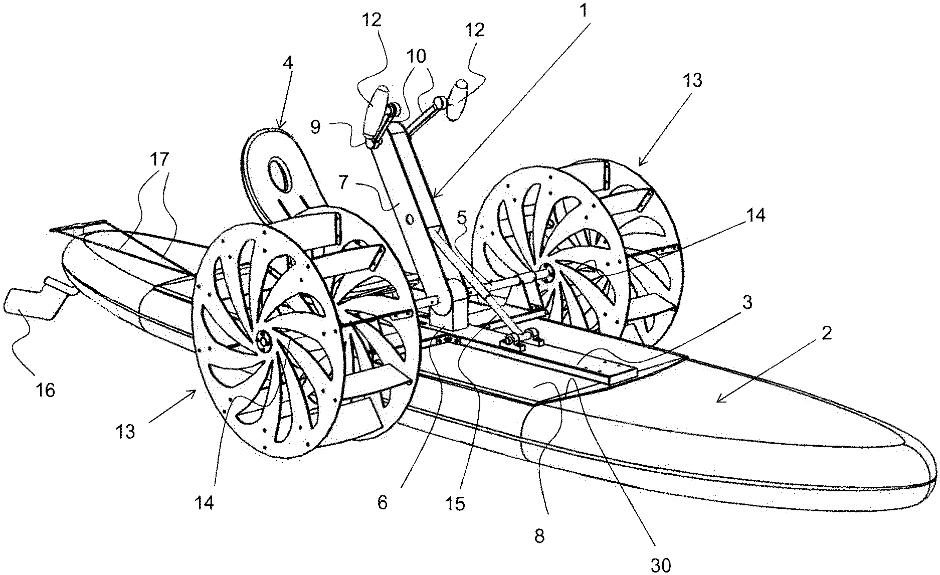
[0012] FIG. 1: A watercraft in the form of a paddle or surfboard with the invented drive module with handles for manual drive;
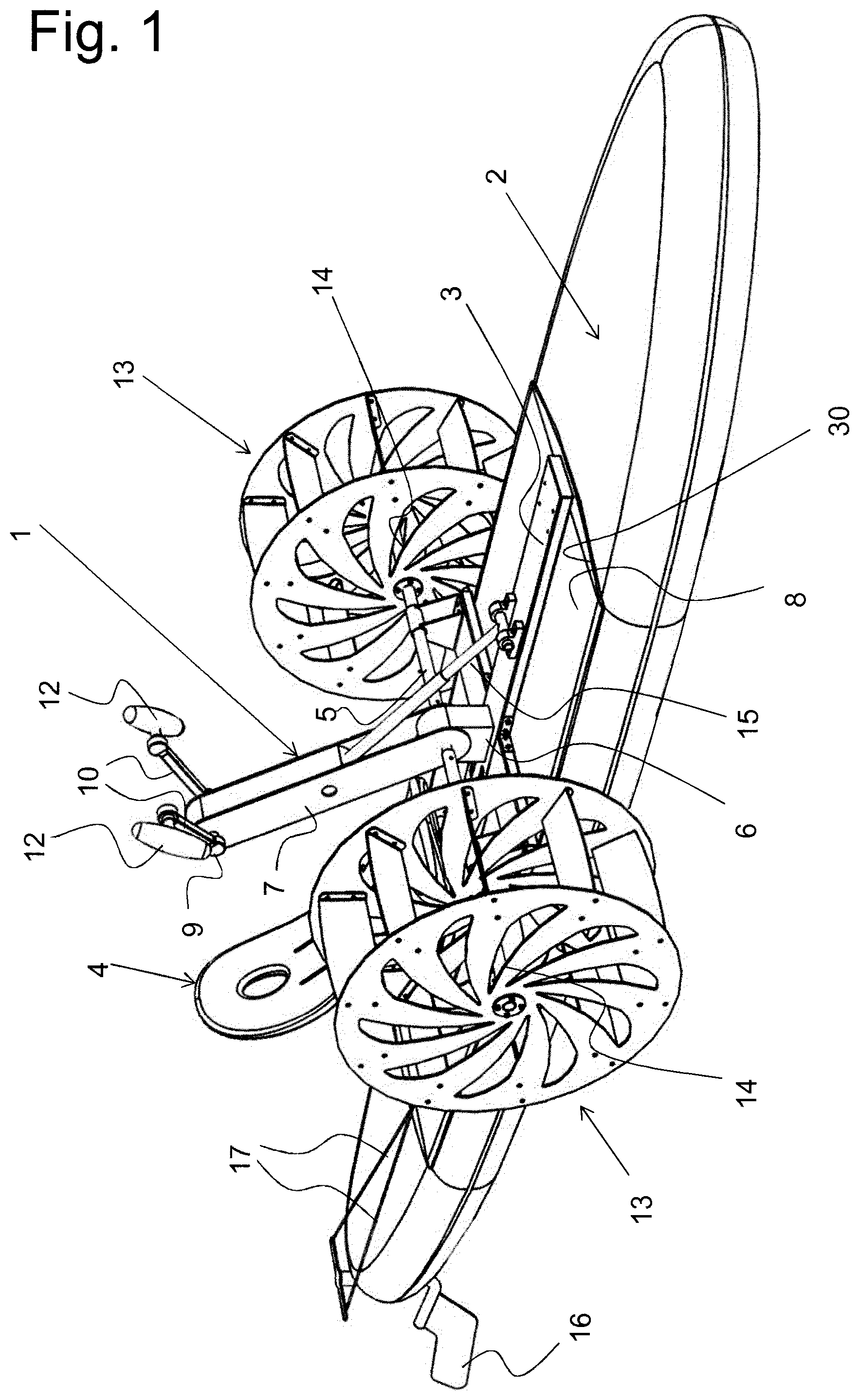
[0013] FIG. 2: A chain drive wheel with pedals and handles for optional operation with the feet or hands;
[0014] FIG. 3: A chain drive wheel with pedals and hand grips as shown in FIG. 9 with pedals and hand grips that can be folded in at the cranks for one or the other type of use;
[0015] FIG. 4: The power transmission from the chain drive wheel to a drive axle for the paddle wheels in a side view;
[0016] FIG. 5: The transmission of power from the chain drive wheel with handles to a drive axle for the paddle wheels, seen in the longitudinal direction of the vessel;
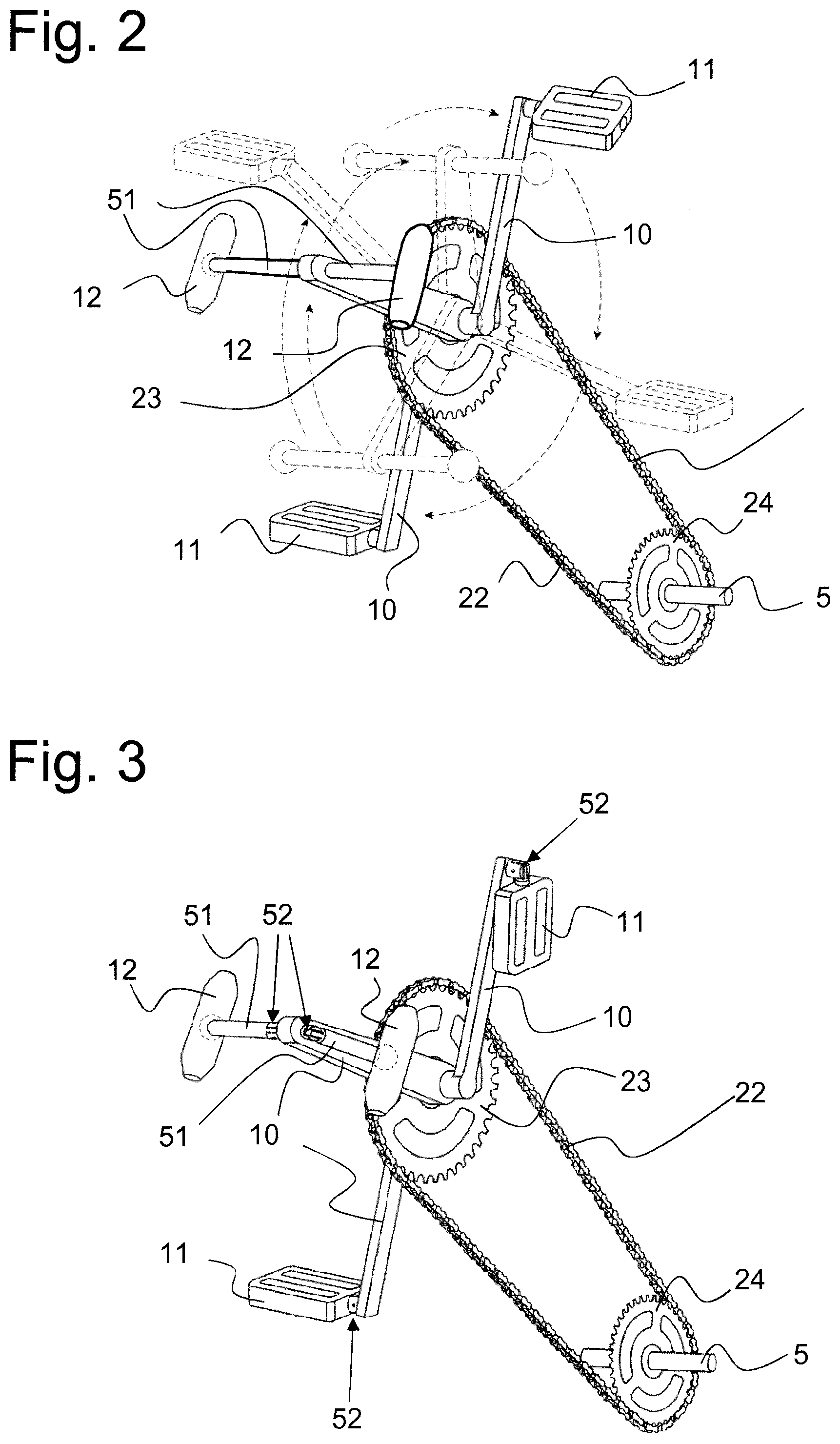
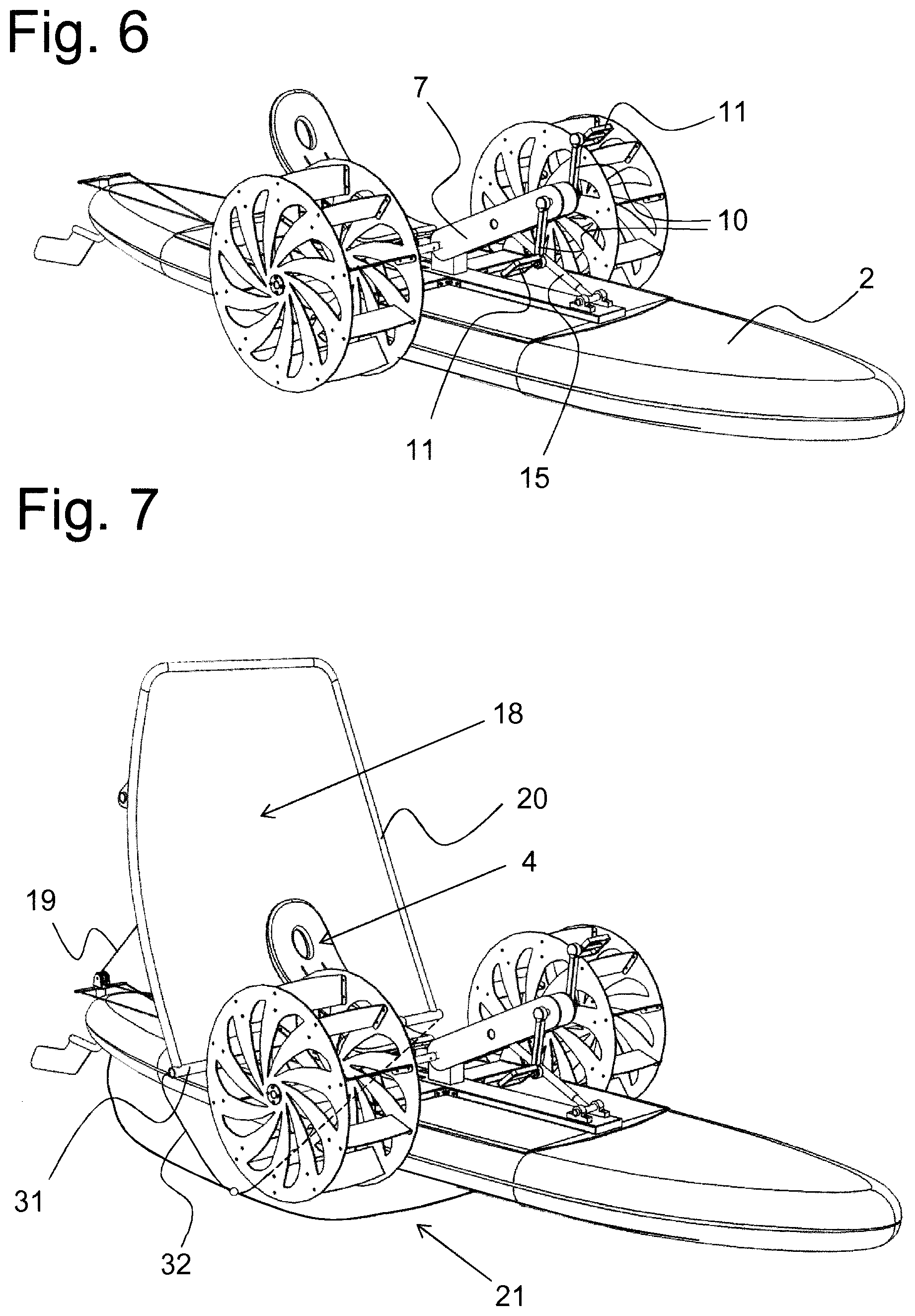
[0017] FIG. 6: A watercraft in the form of a paddle board or surfboard with the drive module of the invention with pedals for propulsion by feet;
[0018] FIG. 7: A watercraft in the form of a paddle or surfboard with the propulsion module of the invention with pedals and a downwind sail;
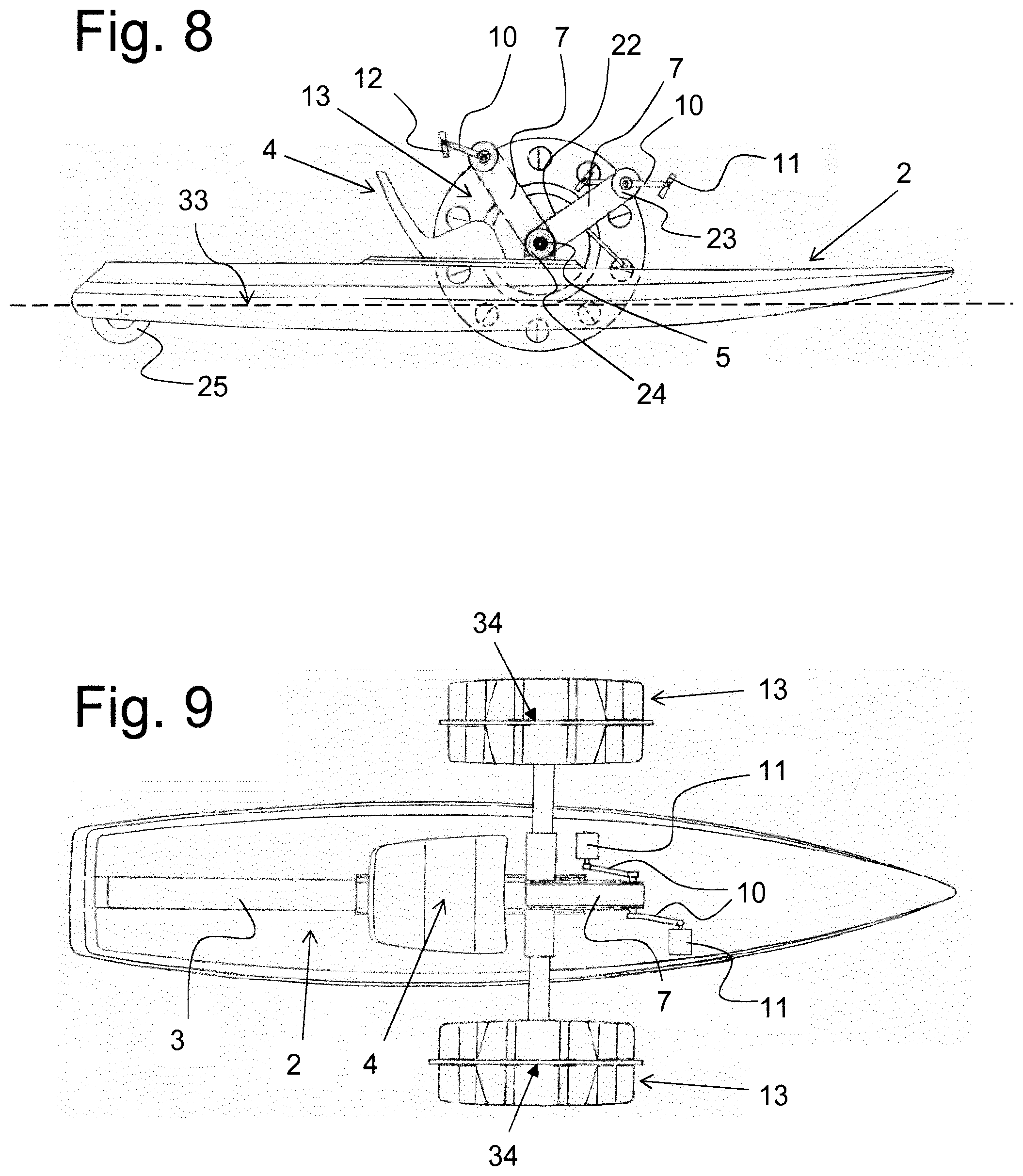
[0019] FIG. 8: A watercraft in the form of a paddle or surfboard with the propulsion module of the invention viewed from the side, with the profile supporting the crank shown in a pivoted position for foot propulsion and a different position for hand propulsion;
[0020] FIG. 9: The vessel as shown in FIG. 4, seen from above;
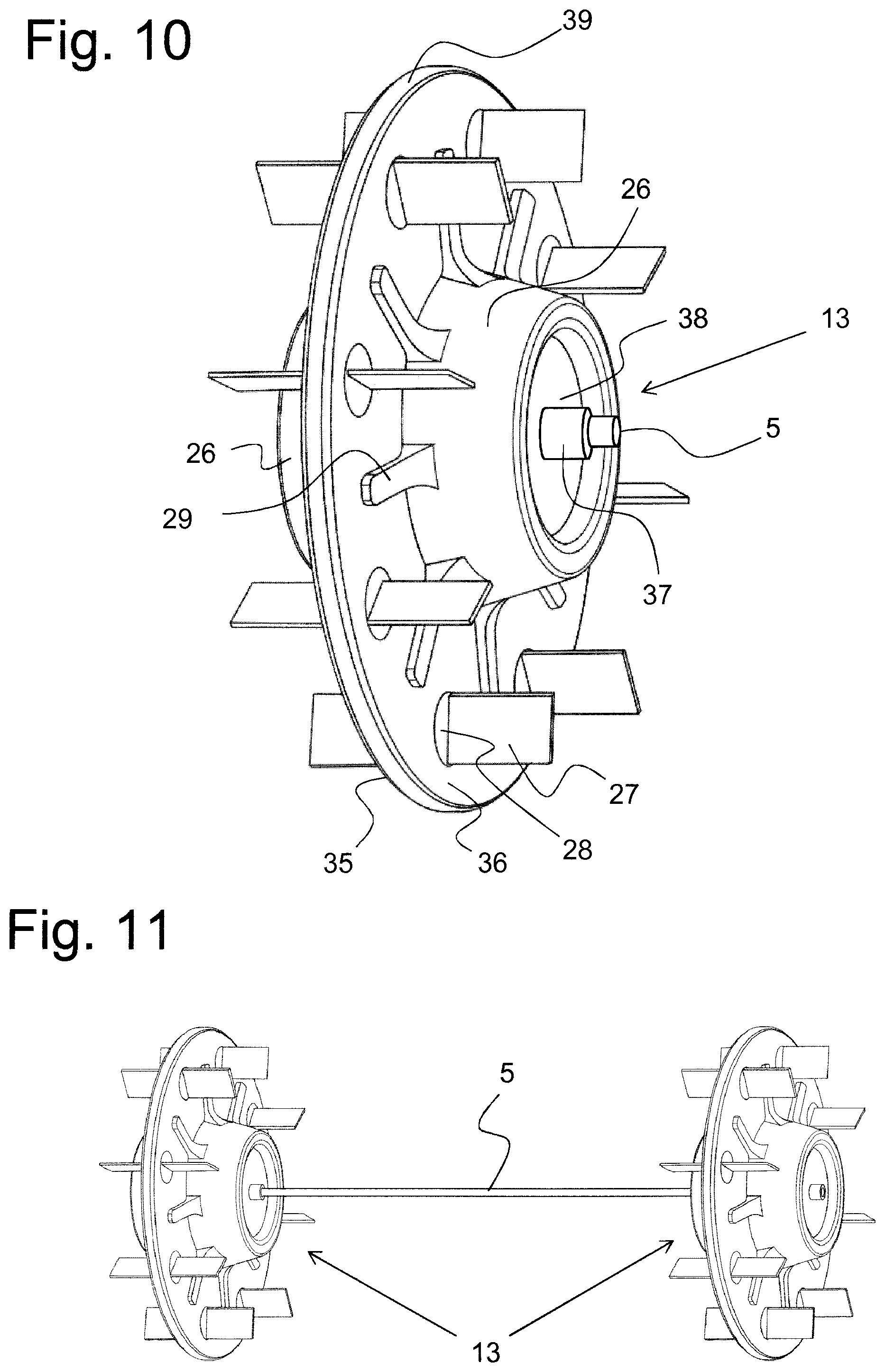
[0021] FIG. 10: A single paddle wheel of the propulsion module;
[0022] FIG. 11: A pair of paddle wheels connected by a shaft as an axle;
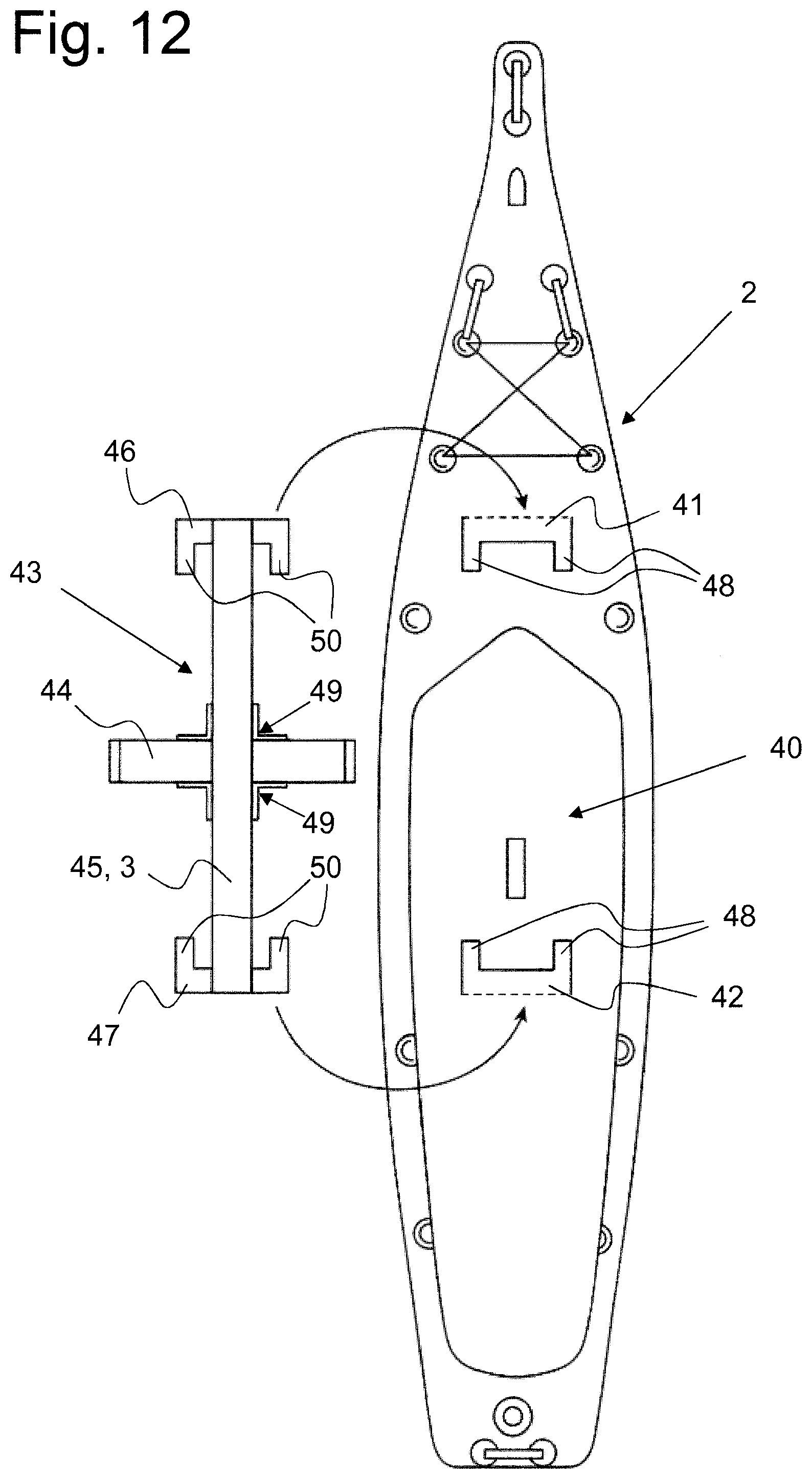
[0023] FIG. 12: An inflatable paddle or surf board with an associated support chassis for the propulsion module, so that it can be connected to the paddle or surf board without the need for tools;
[0024] FIG. 1 shows an example of a watercraft with the drive module 1 according to the invention. In principle, this drive module 1 can be combined with any boat-like buoyancy body 2. This boat-like buoyancy body 2 and various versions can be used. A stand-up paddle board (SUP) comes into question, as such are mainly used in inflatable versions, although fixed SUP boards are also available. Further it can be a surfboard, but also a slim boat such as a racing rowing boat, or even a narrow boat with a side boom or even a catamaran or trimaran can be considered. The drive module 1 is here as an example mounted on a paddle- or surfboard 2, so that the associated paddle wheels 13 can be driven either with crank handles 12 or with foot pedals. The drive module 1 is basically designed to be mounted easily and quickly on a paddle- or surfboard 2 without the need for tools. An existing surfboard 2 or a stand-up paddle board can be used as paddle or surfboard 2, or a board 2 specially designed for drive module 1 can be used as a buoyancy body. Conventional paddle or surfboards are made of solid material, usually a foamed plastic, which is poured or pressed into a mould and then remains dimensionally stable. The boards are stiff and in the water they generate enough buoyancy to carry at least one person. If such a board 2 is equipped with a drive module 1, this module 1 must therefore not be too heavy, so that the buoyancy generated by the board is sufficient to carry module 1 together with the rider. Preferably, the drive module 1 is built from aluminium profiles and the associated paddle wheels 13 are made of aluminium sheets. In a special design the paddle wheels 13 can be made of plastic and form buoyancy bodies, as will be shown below. Instead of a paddle or surf board, an inflatable "board" can be used, which can, for example, be made of a three-dimensional hollow body of foil material with internal partitions welded together to form separate chambers, which can be filled individually with compressed air so that, when all chambers are filled, board 2 takes on a defined shape. Alternatively, board 2 may also be constructed or assembled from a number of separate hollow bodies each made of plastic film material, by welding these hollow bodies together so that when inflated they form a rigid board, similar to a paddle or surfboard made of solid material.
[0025] Finally, the board may also be made of plastic sheets or aluminium sheets, which form the underside and the top, and where the flanks are also made of plastic sheets or aluminium sheets. In the case of plastic sheets, they are welded or glued together along their edges to form a seal, and in the case of aluminium sheets, they may be riveted or welded. In the case of such a hollow body made of aluminium sheets or of plastic sheets, a rubber balloon of similar shape is inserted into the interior, which is then inflated and its outer skin clings to the inside of the hollow body, ensuring that this hollow body is always filled on its inside by an inflated rubber balloon and thus reliably generates the necessary buoyancy. Instead of a rubber balloon, a suitably shaped buoyancy body can also be built into the interior of the hollow body, for example one made of polystyrene, or the hollow body can be filled directly with expanded perlite. As an alternative, one or more bags made of plastic film can be filled with expanded perlite and stowed inside the hollow body so that they fill its interior volume tightly before the hollow body, whether it is made of plastic sheets or aluminum sheets, is closed. This creates an unsinkable board. Expanded perlite is produced from an inert volcanic rock and is therefore ecologically completely harmless. Expanded perlite weighs about 70 grams per litre.
[0026] A drive module 1 is built onto such a board, which allows a very simple and quick change from a pedal drive with pedals to an operating mode for crank handles. The basic idea behind this is to achieve large quantities with a muscle-powered board that can be used by everyone, so that the production costs are correspondingly low and, thanks to the large series, the board is also affordable for the disabled. If such a boat were to be designed exclusively for disabled people, it would regularly become far too expensive to produce, because it could only be sold in small quantities. However, the board with the drive module according to the invention can be equipped with pedals as well as with hand cranks and can then be used by the broad mass of the non-disabled as a trendy leisure watercraft. Equipped with hand cranks, it can also be used by handicapped people, such as wheelchair users, as a highly welcome enrichment and for physical activity on the water, which greatly improves their quality of life.
[0027] As can be seen in FIG. 1, drive module 1 includes a central rail 3 on which the rest of drive module 1 is mounted. This includes the drive unit with the shaft 5, which extends transversely to rail 3 and carries a paddle wheel 13 at each of its two ends. On rail 3 there is a bearing block 6, in which the shaft 5 is rotatably mounted by means of ball bearings or plastic plain bearings. Furthermore, a profile 7 made of aluminium sheet or plastic is attached to the shaft 5 so that it can swivel. This hollow profile forms a housing inside which a secondary drive is housed. This secondary drive can, for example, be a roller chain or toothed belt drive, or a cardan drive. The toothed belt or the roller chain then runs around a drive wheel at the top, which sits on the crank axle 9, to which cranks 10 are attached on both sides of the drive wheel, which are either equipped with crank handles 12 at their ends as shown here, or are equipped with pedals for a foot drive instead of crank handles. Changing from crank handles 12 to pedals can be done very quickly and without tools by clicking these parts onto the crank rods by means of snap locks, against the force of a built-in spring. To release, a push button is pressed and the pedals or crank handles can be pulled outwards towards the crank rods. The drive wheel inside the outer end section of the square profile 7 is provided with a toothing on the outside on which the roller chain or even the toothed belt fits. The roller chain or the toothed belt then drives the drive wheel inside the bearing block 6 in the lower end area of the profile 7, which has the same toothing on its periphery. Thus, if the crank axle 9 is turned by operating the crank handles or pedals, the driving force is transmitted to the output wheel on the shaft 5 by means of the roller chain or toothed belt, and thus the shaft 5 is set in rotation and so are the paddle wheels 13 located at its end sections. As an alternative to a drive via a roller chain or toothed belt as a secondary drive, a cardan drive can be used, as has already been implemented on bicycles. In this case, the crankshaft drives a crankshaft via a spur gear, and this drives this shaft and thus the paddle wheels 13 via another spur gear on shaft 5.
[0028] The driver's seat 4 is equipped with a backrest and is arranged on rail 3 so that it can be moved longitudinally along its length. The seat 4 can be moved back and forth in many positions and can engage in any position on rail 3, for example by means of a spring-loaded pawl via a conveniently operated hand lever, whereby the pawl engages in a rack running longitudinally on the rail. In addition, the steepness of the backrest, i.e. the angle between it and the seat surface, can be adjusted to achieve the optimum sitting and back position for each user.
[0029] The rail 3 can also be permanently mounted on a base plate 8. In this case, this base plate 8 can be advantageously inserted into a recess 30 provided on the upper side of the board 2 and secured in this recess 30 by means of simple sliders on the edge of the recess 30 on the upper side of the board by pushing these sliders over the edge of the base plate 8. Instead of a recess, holders mounted on the board can also be used, in which the base plate 8 fits and with which it can be firmly anchored to the board 2. The base plate 8 is dimensioned so large that all forces acting on the rail 3 can be sufficiently withheld and absorbed.
[0030] The swivel position of profile 7, in this case a square hollow profile or at least one U-profile open at the bottom, is held in a definitive swivel position by strut 15. This swivel position can be changed by altering the length of strut 15. Thus, from the swivel position shown here, profile 7 can be swivelled even further in the direction of seat 4, or on the other hand in the direction towards the bow of board 2. In each swivel position the strut 15 can be locked and secured. For this purpose the brace 15 can be formed by tubes or profiles that can be telescopically inserted into each other, with a number of cross holes into which a safety pin, which is held by a safety chain, can then be inserted. This allows a very large number of swivel positions to be set and secured, so that together with the seat adjustment an ideal setting can be found for every rider's height, whether for manual drive as shown here or for pedal operation. A rudder 16 can be attached to the stern of the board by clamping or screwing it on, which can be swivelled from the seat by means of a linkage or cable pulls 17.
[0031] FIG. 2 shows a sprocket 23 and the corresponding output sprocket 24 for driving the shaft 5. The shaft to this sprocket 23 is equipped with both cranks 10 for the pedals 11 and cranks 10 for the handgrips 12 and their distance rods 51 to the cranks 10, offset in the circumference of the shaft. The movement circles of these pedals 11 and handgrips 12 are marked with dotted lines. The sprocket 23 can therefore be driven either by the pedals 11 or by the handgrips 12. So that the pedals 11 do not get in the way of the handgrips 12 during manual operation and vice versa, the pedals 11 and the handgrips 12 can be folded up to fit the cranks 10.
[0032] This is shown in FIG. 3. As can be seen here, the pedals 11 and the distance rods 51 to the handgrips 12 are each held by a hinge element 52 on the cranks 10. The hinge elements 52 are designed in such a way that they can be pulled apart piece by piece against the force of an internal spring by means of a slotted hole in the outwardly pivoting element through which the fixed pivot pin on the other element passes. In each end position of the 90.degree. swivel range, the outwardly located swivel element can rest on the other and to a certain extent snap into it, so that a fixed setting is maintained in both end positions. In foot operation, the pedals 11 are then swung out and the handles 12 with their spacer rods 51 resting on the crank 10 are folded in and do not interfere with foot operation. In manual mode, the handgrips 12 with their spacer rods 51 are swivelled out and the pedals 11 folded in and resting on the crank 10 and do not interfere with the manual mode. Thus, by simply folding in or out the distance rods 51 and handles 12 or the pedals 11, it is possible to change to the desired drive mode.
[0033] FIG. 4 shows the drive seen from the side. The shaft forming the crank axle 9 can be adjusted by means of an adjustment mechanism 53 on profile 7, so that the chain can be tensioned as required. FIG. 5 shows the drive for manual operation in a longitudinal view on the hull. The cranks 10 do not run at right angles to the crank axis 9, but are arranged at a slight angle to the outside. Spacer bars 51 are attached to the outer ends of the cranks 10. The outer ends of these bars carry the handles 12, which can be rotated on them and are aligned in an ergonomically optimized way.
[0034] A setting for foot pedal operation is shown in FIG. 6. As can be seen in this FIG. 6, the profile 7 is swung forwards from the position in FIG. 1 and secured in a position in which the strut 15 is shortened accordingly and in which the profile 7 is directed forwards and upwards at an angle of about 25.degree. on board 2. For a taller rider it can be swung further towards board 2. The limit is the position of profile 7, where the rider's heels just barely touch the top of board 2 when pedalling. The drive module 1 can be assembled using only one rail 3 as shown here, by screwing this rail 3 onto the body of the board. In the case of a board 2 made of solid material, e.g. a foamed material, holes can be drilled through the board 2, through which screws can be inserted from below, which pass through the board 2 through its material upwards and protrude a few centimetres from the board surface with their thread at the top. Rail 3 can then be placed over these screw ends with appropriate holes and secured with lock nuts or wing nuts. The paddle wheels 13 are made of plastic or aluminium sheet and can then be fitted over one or more longitudinal grooves in the end sections of the shaft to fit exactly over them. For this purpose, the bushes matching the shaft end sections are fitted with corresponding inwardly projecting ribs in the center of the impellers 13. In this way the torque of the shaft can be transmitted to the paddle wheels 13 and at the same time the paddle wheels 13 can be quickly disassembled and reassembled. The two ends of the shaft 5 can be provided with threads onto which a lock nut can be screwed and secured with a cross pin. Alternatively, they can also have only a diametric bore into which a locking pin can be inserted after the paddle wheels 13 have been fitted.
[0035] FIG. 7 shows a variant of drive module 1, which additionally includes a sail 18 for tailwind. This sail 18 is mounted in a frame 20 and is located behind the driver's seat 4. It can be swivelled up and down around the frame tube 31. A spring pushes it upwards, where it finds a stop in an end position as shown here. On its rear side you can see a cable 19. By pulling in the cable 19 against the force of the spring, the frame 20 can be swung out with this sail 18 by means of a hand crank, so that the sail 18 loses its effect. The material of the sail 18 can be an ordinary canvas or a thin plastic foil, but also a flexible solar panel on a foil. Especially when swung down or only slightly swung up, it is then optimally directed towards the sun, depending on the position of the sun, for the accumulation of sunlight and for the photovoltaic conversion of the same into electrical energy, which can be stored in an associated battery with up to 48V voltage and e.g. 10 Ah capacity, which is common for electric bicycles, and which is best placed behind the driver's seat 4.
[0036] Optionally, board 2 can be equipped with a centerboard 21. For this purpose a central longitudinal slot is provided in the rear area of board 2, into which the centerboard 21 can be inserted from top to bottom, or a centerboard 21 is mounted on the bottom side of the board around a swivel axis and stabilized on both sides with thin wire ropes 32. This allows the wind to be used even better, especially if the tailwind sail 18 is additionally mounted to swivel around its vertical axis, for example on a turntable on which the tube 31 of the frame is mounted. In this case, with such a pivoting sail, the stability of the boat becomes of much greater importance, which is the purpose of the paddlewheels 13, which enclose buoyancy bodies, as shown in FIGS. 10 and 11.
[0037] To support the muscle drive, the shaft 5 inside the bearing bracket 6 can be equipped with a wheel hub motor that draws its energy from the battery mentioned above and is supported by the bearing bracket 6, thus enabling the shaft 5 to rotate in the same way as such a wheel hub motor on an electric bicycle can rotate a bicycle hub. There are also motor concepts on bicycles where the electric motor is located directly in front of the bottom bracket and drives the crank axle. Such a concept can also be installed in the bearing block 6. It can be controlled in the same way as an electric bicycle, in that a pedelec drive control system supports the torque generated by muscle power in several selectable stages and provides additional torque. So as soon as the rider drives the cranks 10, either with his feet or with his hands, the electric drive assistance kicks in. On the other hand, the control system can also optimally provide a purely electric drive that is independent of pedalling, whereby the power is then infinitely variable via a handle or lever.
[0038] As a special feature, one of the cranks 10 on crank axle 9 can also be mounted on the crank axle rotated by 180.degree.. Then they are operated by hand in parallel instead of alternately like the pedals of a bicycle, which some riders find more comfortable.
[0039] FIG. 8 shows a watercraft with the drive module invented for a paddle or surfboard 2 seen from the side, without the right paddle wheel to give a view of the seat and the drive. As you can see here, two swivel positions of the profile 7 are drawn simultaneously. On the one hand profile 7 is swivelled forward towards the bow on the right side of the drawing, for a pedal drive, and on the other hand swivelled backwards, for a hand drive. In this FIG. 8 you can also see the drive wheel 23 at the cranks 10, the roller chain 22 or the toothed belt connecting the drive wheel 23 with the driven wheel 24 at the shaft 5. Further on, the here left paddle wheel 13 is drawn sitting on the shaft 5. The water line 33 is at the occupied and watered board at the level where the paddle wheels are only immersed in the water with their area where the paddles are attached, as can be seen from FIGS. 10 and 11. The board 2 as shown here in FIG. 8 is still equipped with a wheel 25 at the stern, which can be swivelled from the driver's seat 4 by means of cables or a linkage, so that it can act as a rudder in the water, and can be locked in a straight line for launching and unloading. It is then a great help when launching and recovering on a sloping surface or on a beach, so that even a single person can launch and recover the watercraft easily and without much effort.
[0040] FIG. 9 shows the watercraft according to FIG. 6 in a view from above. Here you can see the rail 3, which extends in the middle of the board 2 in its longitudinal direction. On this rail 3 the seat 4 can be adjusted back and forth and locked in any position. Also the inclination of the seat 4 and its backrest can be adjusted, so that the seat 4 is mounted on a sledge on rail 3 and can be swivelled around its transverse axis. In the illustration shown, the profile 7 is tilted forward and adjusted for a foot pedal drive. The paddle wheels 13 protrude over the sides of the board 2, so that their wheel centers 34 are about half a board width outside the sides of the board.
[0041] FIG. 10 shows a single special paddle wheel 13 of drive module 1 in a perspective view. It is made of plastic and consists here of two wheel discs 35, 36, which are formed with a bulge in the center area towards the outside. These bulges 26 come to rest on each other when the two wheel discs 35, 36 are placed on top of each other as shown here and are welded or glued together to form a seal. The inner peripheral edges of the bulges 26 are then pressed together to form a seal, and the peripheral edges are fitted with seals. The bushings 37, which receive the shaft 5, are clamped sealingly on the outside with the flat outer discs 38, so that the transmission of the torque of the shaft 5 to the paddle wheels 13 is ensured and at the same time the cavity formed by the bulges 26 is sealed against the outside and remains dry on the inside. Thus such an impeller 13 with its cavity formed by the bulges 26 acts as a buoyancy body. In the normal position of the board 2 occupied by one person, the hollow bodies of the left and right paddle wheel 13 do not dive into the water at all or only very slightly and in the latter case they stabilize the normal position like outriggers on a dugout canoe. If the boat heels due to the rider leaning sideways or due to the influence of the wind, especially when a sail 18 is set, the increased buoyancy of the deeper immersed paddle wheel will limit the heeling. In the peripheral area the paddle wheel discs are provided with axial bores into which turntables 28 are inserted, which carry a paddle 27 on each side. The swivel position of the paddles 27 can be adjusted in such a paddle wheel 13, similar to a controllable pitch propeller. The angle of attack of the paddles 27 is slightly increased for fast sailing. The turntables 28 can be slightly tapered towards the inside and the outer ones visible here can be braced with the inner ones with axially running screws which are not visible here. A rubber ring in the bore hole also creates a watertight seal towards the inside. In addition, reinforcing ribs 29 are also visible on this paddle wheel 13, which can be provided on the outer side visible here as well as on the inner side for general stiffening of the paddle wheel 13.
[0042] These paddle wheels 13 can be fitted with rubber tyres 39 at their periphery. The paddle wheels can even be designed as a rim on their outer circumference, on which a pneumatic tire can even be mounted, as on a bicycle rim. On the one hand this makes it easier to move the vessel on firm ground, especially if the stern is equipped with a freely pivoting stern wheel 25 as shown in FIG. 8. The size of the paddle wheels 13 makes it much easier to push the watercraft on uneven ground and in sand. In addition, the paddle-wheels 13 are then used for launching and recovering the watercraft on a gently sloping beach or on a ramp for launching and recovering boats. A wheelchair user rolls up to a board 2 equipped with drive module 1 and thus a watercraft ready for take-off behind the paddle wheels 13 as close and parallel as possible to the board 2 and can then in many cases independently change over from the wheelchair to the seat 4. Afterwards he can approach the watering ramp on the paddle wheels 13 and the stern wheel by operating the hand cranks and then down into the water. Conversely, if the watering ramps are not very steep, he can approach them from the water, or on a shallow beach he can approach them from the water until the paddle-wheels roll aground, and then drive up the ramp or beach with the hand cranks until the vessel is drained. For this purpose, the secondary drive can be equipped with a reduction gear, just like a bicycle, so that with a low gear ratio, even considerable gradients can be overcome when driving slowly. For this purpose, the secondary drive can be equipped with a gear change, just like on a bicycle, at the drive wheel or at the output wheel or even at both, so that a very small gear ratio can be selected for launching on a ramp, in order to be able to overcome the gradient with a force that can be easily applied. Of course, this dewatering by driving the paddle wheels 13 is greatly facilitated if the drive is still electrically assisted. Once dry, the wheelchair user can drive the watercraft back to the vicinity of his wheelchair and change over to it.
[0043] For further stabilization of the paddle wheels 13, the associated shaft 5 can be equipped with bearing blocks that can be attached to the edges of the board 2 or with bearing blocks that can be clamped to the edge areas of the board 2, but are divisible but not shown here, so that the shaft 5 is then mounted on the board at three points between the two paddle wheels 13.
[0044] Thanks to the wide track width of the paddle wheels 13 with integrated buoyancy bodies, there are no balance problems whatsoever with a paddle or surfboard equipped with drive module 1. Such a board 2 or boat is capsize-proof, even in wind and waves, because the more it heels, the greater the uprighting moment generated by the immersed paddle wheel 13. In addition to a rudder 16 (FIG. 1) in the stern, a rudder with steering linkage or steering ropes can also be mounted in the bow to be operated. The board then guarantees exceptionally good manoeuvrability, even at low speeds, and the optimally designed, slim hull allows peak speeds of up to 12 km/h, which is surprisingly high for a purely muscle-powered watercraft, as determined by tests. Thanks to the minimal draught, full manoeuvrability is guaranteed even in low water levels as well as sea grass and driftwood. Such a watercraft or boat is fast, agile and effortlessly controllable.
[0045] A paddle or surfboard equipped with such a drive module 1 as presented can also be quickly realized with little effort by modifying an existing paddle or surfboard. It is therefore also sensible to offer and sell the drive modules 1 separately, for equipping existing paddle or surfboards. In the simplest case, a base plate 8, which carries the rail 3 and all the components of drive module 1, can be mounted on an existing paddle or surfboard by placing the base plate 8 on the board and applying tension belts running around it in a transverse direction to the board, with which the base plate is immovably braced to the board. The rudder at the stern or optionally also at the bow can be easily clamped to the board with a suitable clamping device. This means that no structural changes need to be made to the board itself.
[0046] FIG. 12 shows a particularly elegant way in which the drive module 1 can be attached to a paddle or surfboard 2 without tools, quickly and safely, and removed again, if the surf or paddleboard 2 is an inflatable model. For this purpose, the paddle or surf board 2 is equipped with a base platform 40 for mounting the drive module on it. This can be a rigid plate made of plastic, wood or steel, or preferably stainless steel, which is firmly attached to the top of the inflatable paddle or surfboard. The connection can be a welding or gluing or it can be realized by a tight screw connection. Furthermore, 2 holding pockets 41 made of wood, plastic or metal are glued, welded or tightly screwed to the upper side of the paddle and surf board. The pockets 41 are U-shaped and open along the dotted line. They form two thigh pockets 48 to hold two reeds which fit into these thigh pockets 48. One such holding pocket 41 is located on the front half of the paddle or surfboard 2 and a second holding pocket 42 is located on the base platform 40 in the rear half of the paddle or surfboard 2. The open sides of the pockets 41, 42 are facing away from each other. A support chassis 43 as shown on the left side of the paddle or surf board 2 is then used to attach the drive module. In the example shown, this support chassis 43 is formed by two intersecting struts 44, 45 made of stainless steel, which are firmly connected to each other. A reinforcement 49 can surround the struts in the crossing area so that they are always firmly connected to each other at right angles. At each end of the longitudinal strut 45 there is an insertion and holding fork 46, 47, which forms two tongues 50 each. If now the inflatable paddle and surfboard 2 is not yet inflated and can therefore be folded, the two holding pockets 41, 42 can be brought closer together. Especially the front holding pocket 41 can be moved closer to the base platform 40 by folding the foil material and in this constellation the tabs 50 of the two insertion and holding forks 46, 47 can then be inserted into the corresponding leg pockets 48 in the holding pockets 41, 42. Afterwards you can inflate the paddle- and surfboard 2. The holding pockets 41, 42 slide apart and the paddle- and surfboard 2 becomes stiff. This creates a strong and firm connection between the carrier chassis 43 and the paddle and surf board 2. The carrier chassis 43 is also supported against lateral inclination thanks to the cross brace 44 on the base platform 40. The longitudinal strut 45 can also be designed directly as a rail 3 in one variant, to accommodate the carriage for the seat 4, so that the latter can be moved along the paddle and surf board 2 on this rail 3.
[0047] When driven by a wheelchair user, the watercraft can be described as an actual paraboat. The drive module 1 with its paddle-wheels 13 together with the shaft 5, the rail 3 with the bearing block 6 and the profile 7 for the cranks 10 as well as the seat 4 form a construction unit which can be easily mounted on a board 2 and screwed to it with a few hand movements. Walking disabled people can even change from wheelchair to boat independently on land, depending on their disability, and then drive into the water via a ramp. This paraboat enables people with walking disabilities to engage in attractive sporting activities in the primeval medium of water, in fresh air and in the great outdoors. For such people, this creates a very high added value in terms of quality of life. With the possibility of quickly changing from foot drive to hand drive and vice versa without having to use tools, and which can then even be done directly on the water at any time, a perfect double function is achieved. This means that the legs or arms can then be trained alternately with activation of breathing.
[0048] For such a paraboat no boat place is required, which for many people is the main limitation for doing water sports, because boat places are generally very limited available. Such a surf or paddle board 2 as well as the corresponding drive module 1 can be transported with a passenger car, an ordinary car. The board 2 can be transported on the roof of the car, and the removable drive module 1 in the boot of the car or otherwise on the roof. The drive module can easily be dismantled into its parts paddle wheels 13, bearing block with shaft 5 and square profile 7, and rail 3 with seat 4. Conversely, to assemble the drive module, first mount rail 3 with seat 4 on the board 2, then place the bearing block 6 with shaft 5 on rail 3 and then mount the two paddle wheels 13 on the end sections of shaft 5. Finally the stern and bow rudder are mounted on the board 2 and the cables are led to the driver's seat 4. Then the paraboat is ready for use. Optionally, the sail 18 can still be mounted on board 3.
LIST OF NUMBERS
[0049] 1 Drive module [0050] 2 Boat-like buoyancy body or paddle or surf board [0051] 3 Rail mountable along the buoyancy chamber [0052] 4 Seat mountable on rail 3 [0053] 5 Shaft mounted transverse to rail 3, for the paddle wheels [0054] 6 Bearing block for the shaft 5 [0055] 7 On the rail 3 Swivelling profile 7 [0056] 8 Base plate for installation in the recess 30 [0057] 9 Pedal crank axle [0058] 10 Cranking the pedal cranks [0059] 11 Pedals for foot drive [0060] 12 Crank handles [0061] 13 Paddle wheels [0062] 14 Shaft end section to which the paddle wheels 13 are attached [0063] 15 Support strut to brace the profile [0064] 16 Rudder at the stern [0065] 17 Cable pulls for operating the rudder 16 [0066] 18 Tailwind sail [0067] 19 Rope for lowering the tailwind sail [0068] 20 Frame of the tailwind sail [0069] 21 Sword [0070] 22 Roller chain or toothed belt [0071] 23 Drive wheel on the crankshaft [0072] 24 Output wheel on the shaft 5 [0073] 25 Stern wheel as rudder [0074] 26 Buoyancy body on the paddle wheel [0075] 27 Paddle on the paddle wheel [0076] 28 Paddle wheel pivot bearing [0077] 29 Reinforcing ribs on the paddle wheel [0078] 30 Recessed recess on top of the board 2 [0079] 31 Pivoting cross tube of the frame [0080] 32 Wire pull for locking the sword 21 [0081] 33 Waterline [0082] 34 Wheel center seen from above [0083] 35 Inner disc of the paddle wheel 13 [0084] 36 Outer disc of paddle wheel 13 [0085] 37 Bushing on flat disc 38 [0086] 38 Flat disc outside at the bulge 26 [0087] 39 Rubber tyres on the paddle wheel 13 [0088] 40 Basic platform for mounting the drive module on it [0089] 41 Front holding bag on the paddle or surfboard [0090] 42 Rear holding bag on the paddle or surfboard [0091] 43 Support chassis for the drive module [0092] 44 Cross brace for lateral support of the carrier chassis [0093] 45 Longitudinal struts to accommodate the rail 3 [0094] 46 Front insertion and holding fork [0095] 47 Rear insertion and mounting fork [0096] 48 Thigh pockets in the holding pockets 41, 42 [0097] 49 Reinforcements in the crossing area of the struts 44, 45 [0098] 50 Tabs to insert into the thigh pockets 48 [0099] 51 Spacer bars for handles [0100] 52 Hinge elements for folding the pedals/handles [0101] 53 Adjusting mechanism
* * * * *
D00000
D00001
D00002
D00003
D00004
D00005
D00006
D00007
XML
uspto.report is an independent third-party trademark research tool that is not affiliated, endorsed, or sponsored by the United States Patent and Trademark Office (USPTO) or any other governmental organization. The information provided by uspto.report is based on publicly available data at the time of writing and is intended for informational purposes only.
While we strive to provide accurate and up-to-date information, we do not guarantee the accuracy, completeness, reliability, or suitability of the information displayed on this site. The use of this site is at your own risk. Any reliance you place on such information is therefore strictly at your own risk.
All official trademark data, including owner information, should be verified by visiting the official USPTO website at www.uspto.gov. This site is not intended to replace professional legal advice and should not be used as a substitute for consulting with a legal professional who is knowledgeable about trademark law.