Stapling System For Use With Wire Staples And Stamped Staples
Shelton, IV; Frederick E. ; et al.
U.S. patent application number 16/916893 was filed with the patent office on 2020-12-17 for stapling system for use with wire staples and stamped staples. The applicant listed for this patent is Ethicon LLC. Invention is credited to Gregory J. Bakos, Jason L. Harris, Frederick E. Shelton, IV.
| Application Number | 20200390442 16/916893 |
| Document ID | / |
| Family ID | 1000005062470 |
| Filed Date | 2020-12-17 |


View All Diagrams
| United States Patent Application | 20200390442 |
| Kind Code | A1 |
| Shelton, IV; Frederick E. ; et al. | December 17, 2020 |
STAPLING SYSTEM FOR USE WITH WIRE STAPLES AND STAMPED STAPLES
Abstract
A staple cartridge system is disclosed which can be interchangeably used with a staple cartridge comprising wire staples and a staple cartridge comprising stamped staples.
| Inventors: | Shelton, IV; Frederick E.; (Hillsboro, OH) ; Harris; Jason L.; (Lebanon, OH) ; Bakos; Gregory J.; (Mason, OH) | ||||||||||
| Applicant: |
|
||||||||||
|---|---|---|---|---|---|---|---|---|---|---|---|
| Family ID: | 1000005062470 | ||||||||||
| Appl. No.: | 16/916893 | ||||||||||
| Filed: | June 30, 2020 |
Related U.S. Patent Documents
| Application Number | Filing Date | Patent Number | ||
|---|---|---|---|---|
| 15191807 | Jun 24, 2016 | 10702270 | ||
| 16916893 | ||||
| Current U.S. Class: | 1/1 |
| Current CPC Class: | A61B 2017/0645 20130101; A61B 17/068 20130101; A61B 17/0644 20130101; A61B 17/072 20130101; A61B 17/07207 20130101; A61B 2017/00398 20130101; A61B 2017/07271 20130101; A61B 17/105 20130101; A61B 17/064 20130101; A61B 2017/07264 20130101; A61B 2017/07228 20130101; A61B 2017/07285 20130101; A61B 2017/07235 20130101; A61B 2017/07214 20130101; A61B 2017/07257 20130101; A61B 2017/07278 20130101 |
| International Class: | A61B 17/072 20060101 A61B017/072; A61B 17/064 20060101 A61B017/064; A61B 17/068 20060101 A61B017/068; A61B 17/10 20060101 A61B017/10 |
Claims
1. A surgical stapling system, comprising: a shaft comprising a proximal end and a distal end; an end effector extending from said distal end of said shaft, wherein said end effector is movable between an open configuration and a closed configuration, and wherein said end effector comprises: a frame; and an anvil extending distally from said frame, wherein said anvil comprises a longitudinal row of forming pockets; a first staple cartridge assembly attachable to said end effector, comprising: a first cartridge body comprising a first longitudinal row of staple cavities; and a plurality of first staples removably stored in said first longitudinal row of staple cavities, wherein each said first staple is comprised of a bent wire, and wherein each said first staple is aligned with a said forming pocket when said end effector is in said closed configuration; and a second staple cartridge assembly attachable to said end effector in lieu of said first staple cartridge assembly, wherein said second staple cartridge assembly, comprises: a second cartridge body comprising a second longitudinal row of staple cavities; and a plurality of second staples removably stored in said second longitudinal row of staple cavities, wherein each said second staple is formed from flat stock, and wherein each said second staple is aligned with a said forming pocket when said end effector is in said closed configuration.
2. The surgical stapling system of claim 1, wherein each said forming pocket comprises a proximal forming cup and a distal forming cup.
3. The surgical stapling system of claim 2, wherein each said first staple comprises a proximal leg formed by a said proximal forming cup and a distal leg formed by a said distal forming cup.
4. The surgical stapling system of claim 3, wherein each said second staple comprises a proximal leg formed by a said proximal forming cup and a distal leg formed by a said distal forming cup.
5. The surgical stapling system of claim 1, wherein said end effector further comprises a jaw configured to receive: said first staple cartridge assembly; and said second staple cartridge assembly in lieu of said first staple cartridge assembly.
6. The surgical stapling system of claim 5, wherein said jaw is rotatable relative to said anvil to place said end effector in said closed configuration.
7. The surgical stapling system of claim 5, wherein said anvil is rotatable relative to said jaw to place said end effector in said closed configuration.
8. The surgical stapling system of claim 1, wherein said first staple cartridge assembly comprises a first jaw attachable to said frame, and wherein said second cartridge assembly comprises a second jaw attachable to said frame.
9. The surgical stapling system of claim 8, wherein said anvil is rotatable relative to said frame to place said end effector in said closed configuration.
10. The surgical stapling system of claim 8, wherein said first jaw is rotatable relative to said frame to place said end effector in said closed configuration when said first jaw is attached to said frame, and wherein said second jaw is rotatable relative to said frame to place said end effector in said closed configuration when said second jaw is attached to said frame.
11. The surgical stapling system of claim 1, wherein said first staple cartridge assembly comprises staple drivers configured to push said first staples out of said first staple cavities, and wherein each said second staple comprises an integrally-formed staple driver.
12. A surgical stapling system, comprising: a shaft comprising a proximal end and a distal end; an end effector extending from said distal end of said shaft, wherein said end effector is movable between an unclamped configuration and a clamped configuration, and wherein said end effector comprises: a frame; and an anvil extending distally from said frame, wherein said anvil comprises a longitudinal row of forming pockets; a first staple cartridge assembly attachable to said end effector, comprising: a first cartridge body comprising a first longitudinal row of staple cavities; and a plurality of first staples removably stored in said first longitudinal row of staple cavities, wherein each said first staple is comprised of a bent wire, and wherein each said first staple is aligned with a said forming pocket when said end effector is in said clamped configuration; and a second staple cartridge assembly attachable to said end effector as an alternative to said first staple cartridge assembly, wherein said second staple cartridge assembly, comprises: a second cartridge body comprising a second longitudinal row of staple cavities; and a plurality of second staples removably stored in said second longitudinal row of staple cavities, wherein said second staples are stamped from one or more flat sheets of material, and wherein each said second staple is aligned with a said forming pocket when said end effector is in said clamped configuration.
13. The surgical stapling system of claim 12, wherein each said forming pocket comprises a proximal forming cup and a distal forming cup.
14. The surgical stapling system of claim 13, wherein each said first staple comprises a proximal leg formed by a said proximal forming cup and a distal leg formed by a said distal forming cup.
15. The surgical stapling system of claim 14, wherein each said second staple comprises a proximal leg formed by a said proximal forming cup and a distal leg formed by a said distal forming cup.
16. The surgical stapling system of claim 12, wherein said end effector further comprises a jaw configured to receive: said first staple cartridge assembly; and said second staple cartridge assembly as an alternative to said first staple cartridge assembly.
17. The surgical stapling system of claim 16, wherein said jaw is rotatable relative to said anvil to place said end effector in said clamped configuration.
18. The surgical stapling system of claim 16, wherein said anvil is rotatable relative to said jaw to place said end effector in said clamped configuration.
19. The surgical stapling system of claim 12, wherein said first staple cartridge assembly comprises a first jaw attachable to said frame, and wherein said second cartridge assembly comprises a second jaw attachable to said frame.
20. The surgical stapling system of claim 19, wherein said anvil is rotatable relative to said frame to place said end effector in said clamped configuration.
21-23. (canceled)
Description
CROSS-REFERENCE TO RELATED APPLICATION
[0001] This application is a continuation application claiming priority under 35 U.S.C. .sctn. 120 to U.S. patent application Ser. No. 15/191,807, entitled STAPLING SYSTEM FOR USE WITH WIRE STAPLES AND STAMPED STAPLES, filed Jun. 24, 2016, now U.S. Patent Application Publication No. 2017/0367696, the entire disclosure of which is hereby incorporated by reference herein.
BACKGROUND
[0002] The present invention relates to surgical instruments and, in various arrangements, to surgical stapling and cutting instruments and staple cartridges for use therewith.
BRIEF DESCRIPTION OF THE DRAWINGS
[0003] Various features of the embodiments described herein, together with advantages thereof, may be understood in accordance with the following description taken in conjunction with the accompanying drawings as follows:
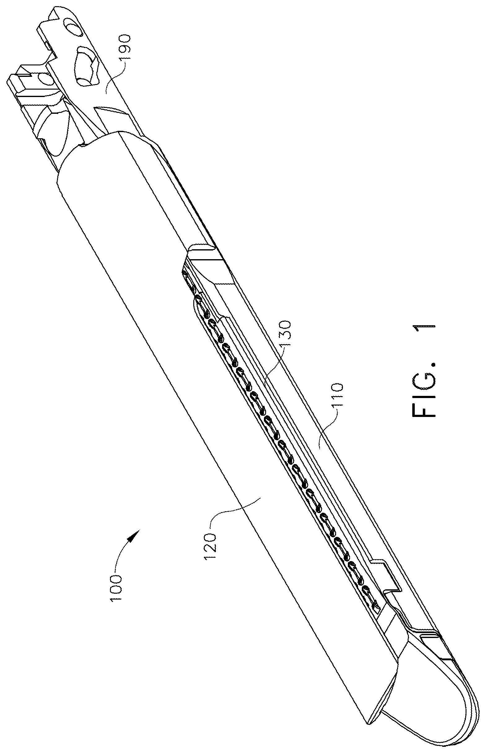
[0004] FIG. 1 is a perspective view of an end effector of a surgical stapling instrument in accordance with at least one embodiment;
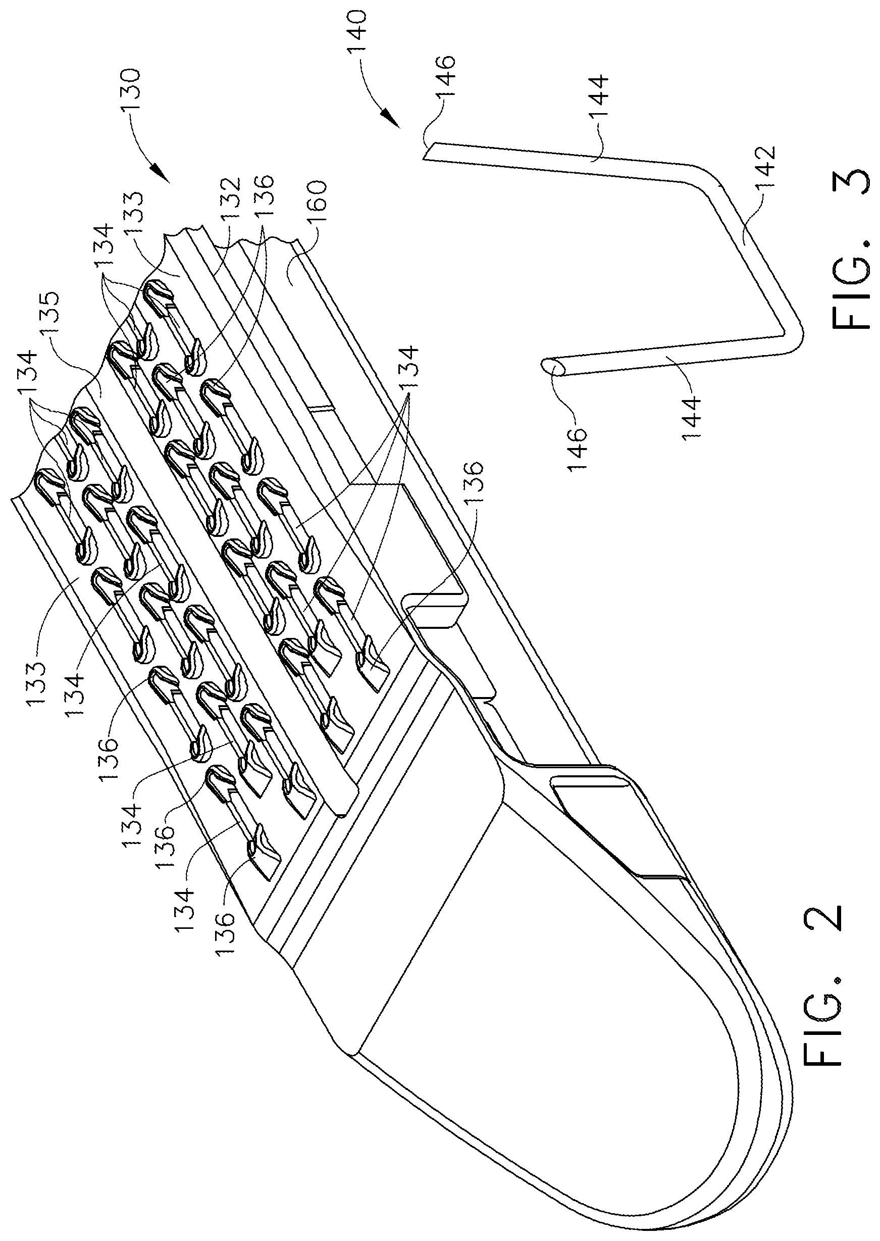
[0005] FIG. 2 is a partial perspective view of a staple cartridge for use with the end effector of FIG. 1;
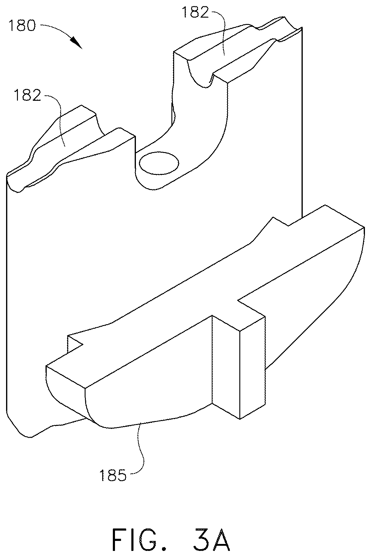
[0006] FIG. 3 is a perspective view of a wire staple removably stored in the staple cartridge of FIG. 2;
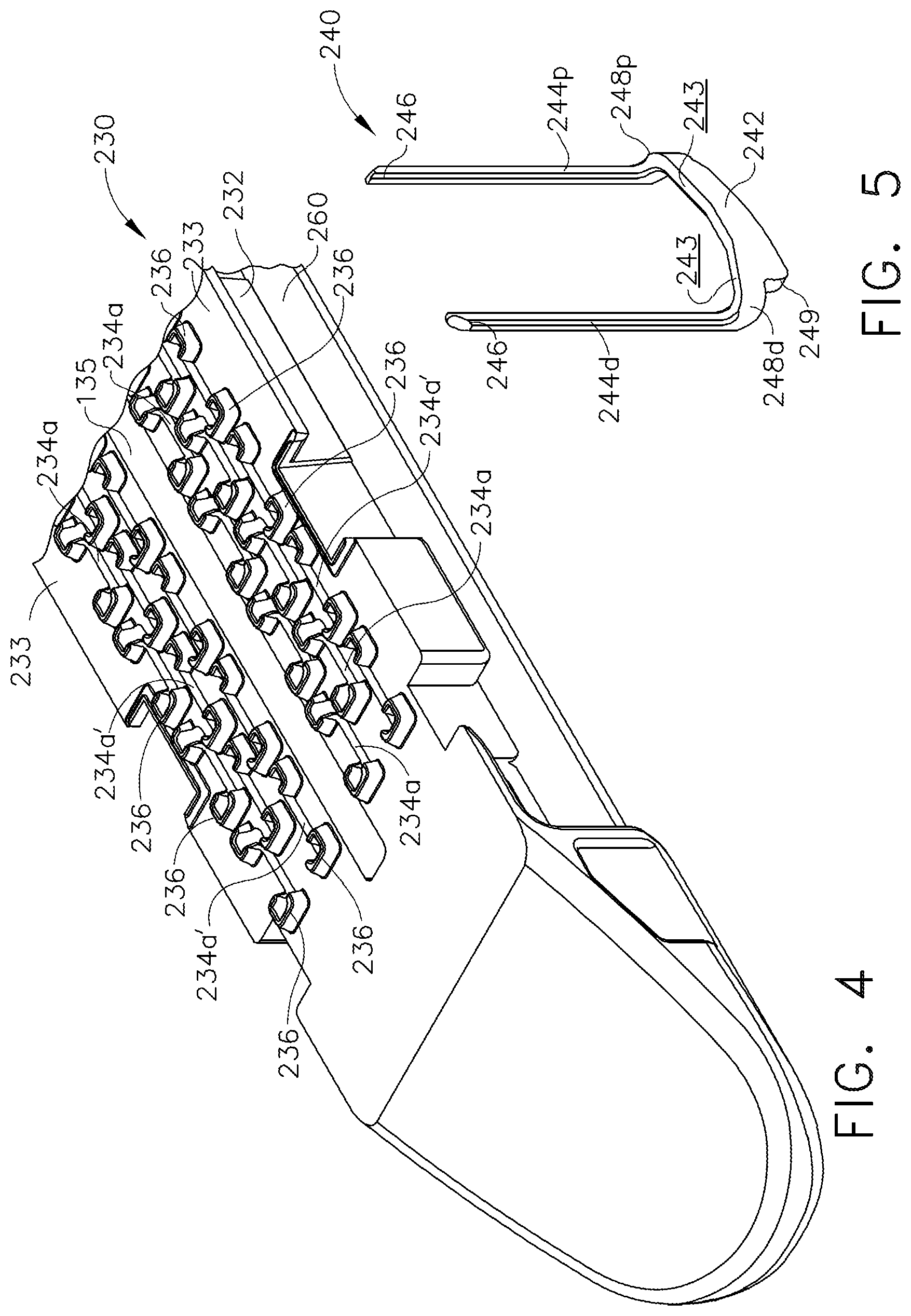
[0007] FIG. 3A is a perspective view of a staple driver configured to eject the staple of FIG. 3 from the staple cartridge of FIG. 2;
[0008] FIG. 4 is a partial perspective view of a staple cartridge for use with the end effector of FIG. 1;
[0009] FIG. 5 is a perspective view of a staple removably stored in the staple cartridge of FIG. 4;
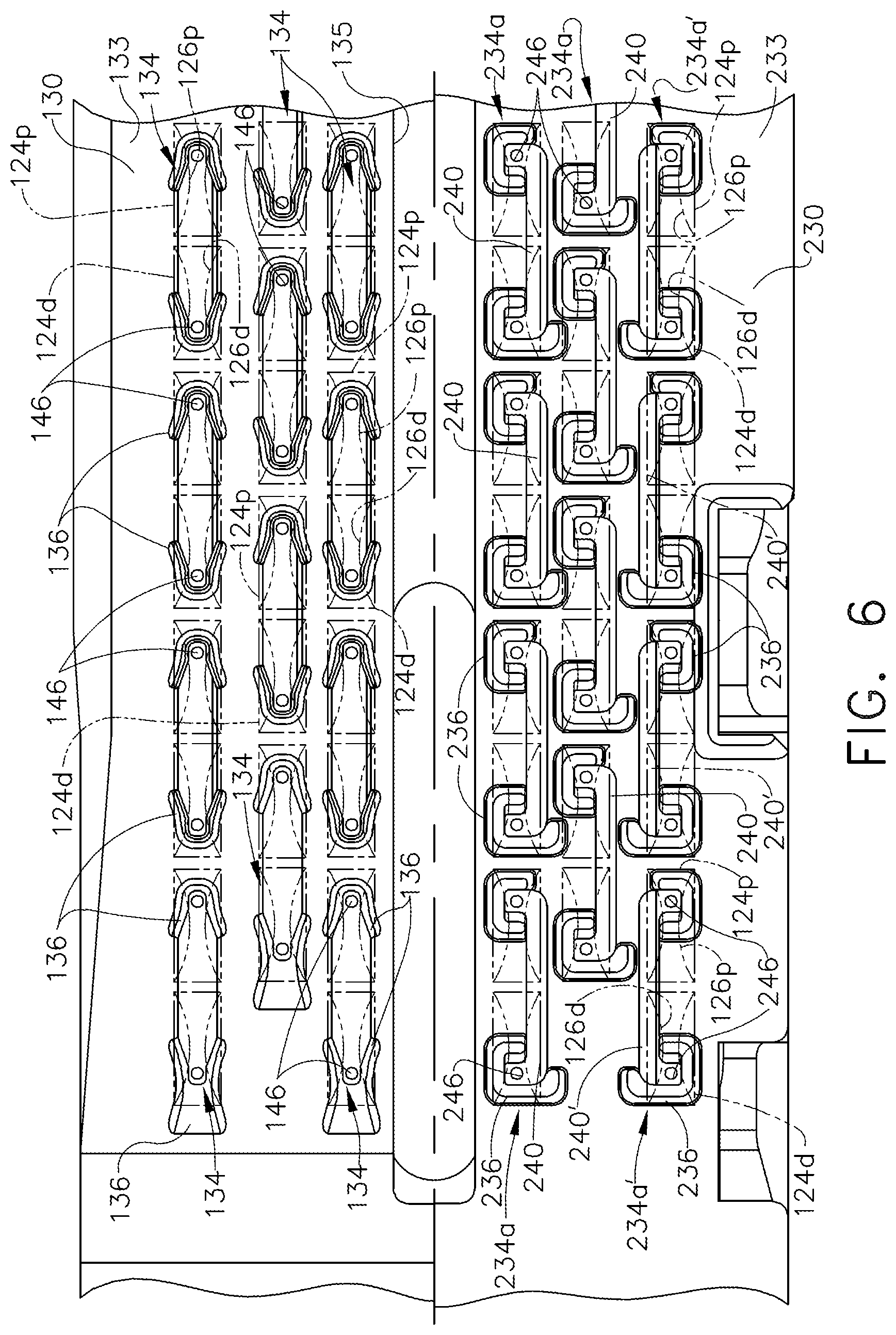
[0010] FIG. 6 is an illustration depicting that the staples of the staple cartridge of FIG. 2 and the staples of the staple cartridge of FIG. 4 are alignable with the forming pockets of an anvil of the end effector of FIG. 1;
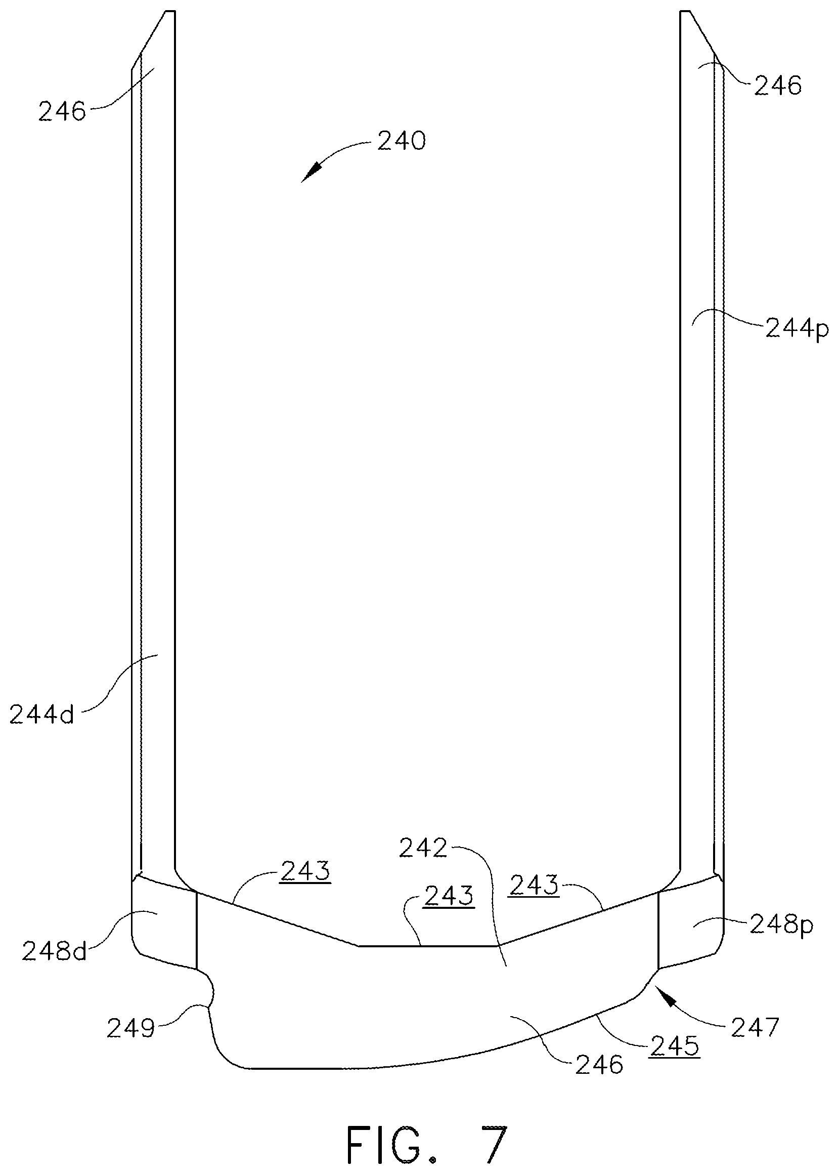
[0011] FIG. 7 is an elevational view of the staple of FIG. 5;
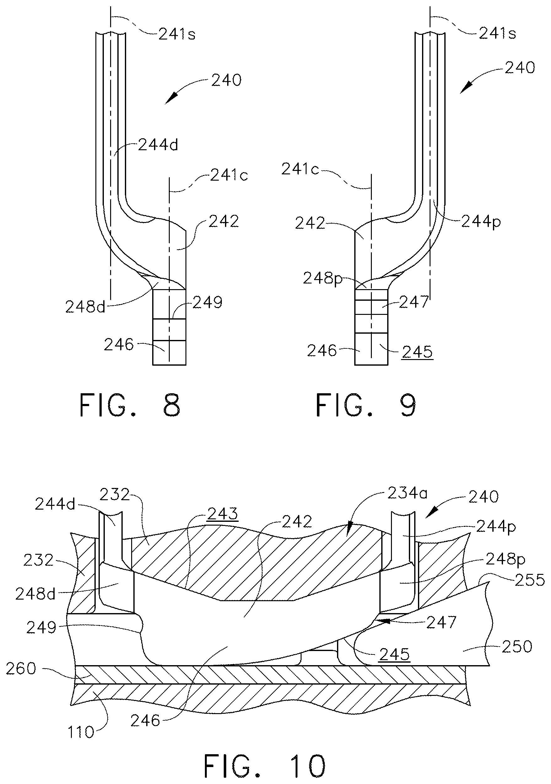
[0012] FIG. 8 is a partial side view of the staple of FIG. 5;
[0013] FIG. 9 is a partial side view of the staple of FIG. 5;
[0014] FIG. 10 depicts a sled of the staple cartridge of FIG. 4 directly engaging the staple of FIG. 5;
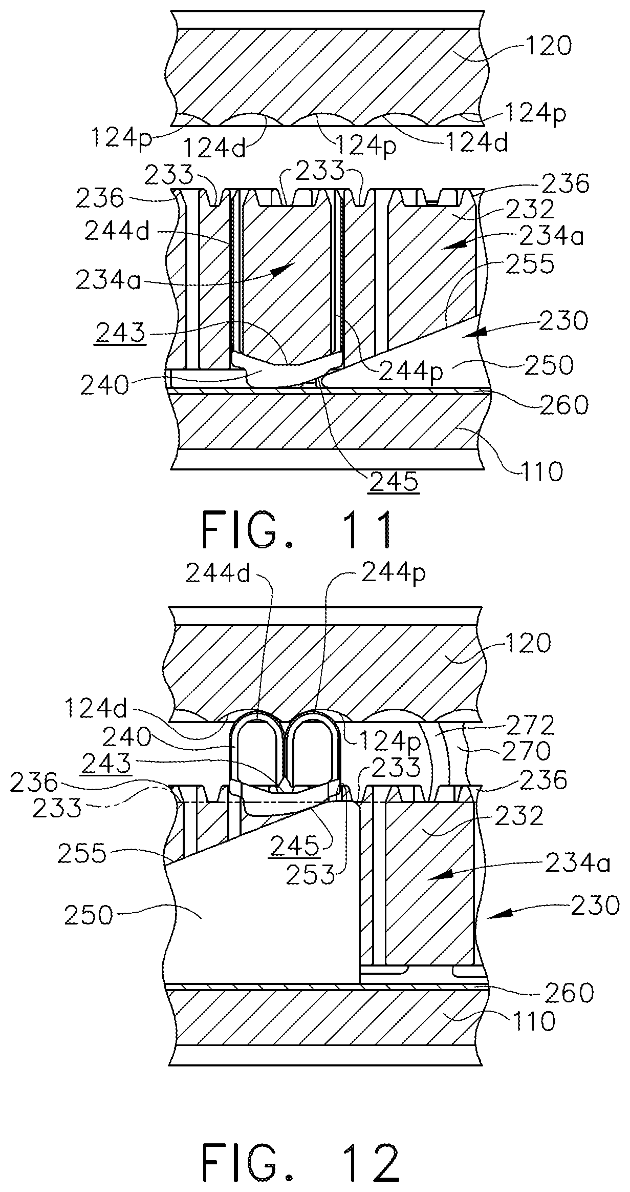
[0015] FIG. 11 is a partial cross-sectional view of the staple cartridge of FIG. 4 illustrating the staple of FIG. 5 in an unfired position;
[0016] FIG. 12 is a partial cross-sectional view of the staple cartridge of FIG. 4 illustrating the staple of FIG. 5 in a fired position;
[0017] FIG. 13 comprises a perspective view and an elevational view of an alternative embodiment of the staple of FIG. 5;
[0018] FIG. 14 comprises a perspective view and an elevational view of a version of the staple of FIG. 5 having non-parallel staple legs;
[0019] FIG. 15 is a partial plan view of a staple cartridge in accordance with at least one embodiment;
[0020] FIG. 16 is a rear elevational end view of a sled for use with the staple cartridge of FIG. 15;
[0021] FIG. 17 is a perspective view of the sled of FIG. 16;
[0022] FIG. 18 is a partial cross-sectional view of a cartridge body of the staple cartridge of FIG. 15;
[0023] FIG. 19 is a partial plan view of an anvil for use with the staple cartridge of FIG. 15;
[0024] FIG. 20 is a partial plan view of a staple cartridge in accordance with at least one embodiment; and
[0025] FIG. 21 is a front elevational end view of a sled for use with the staple cartridge of FIG. 20.
[0026] Corresponding reference characters indicate corresponding parts throughout the several views. The exemplifications set out herein illustrate various embodiments of the invention, in one form, and such exemplifications are not to be construed as limiting the scope of the invention in any manner.
DETAILED DESCRIPTION
[0027] The Applicant of the present application owns the following U.S. patent applications that were filed on Jun. 24, 2016 and which are each herein incorporated by reference in their respective entireties: [0028] U.S. patent application Ser. No. 15/191,834, entitled STAMPED STAPLES AND STAPLE CARTRIDGES USING THE SAME, now U.S. Pat. No. 10,542,979; [0029] U.S. patent application Ser. No. 15/191,788, entitled STAPLE CARTRIDGE COMPRISING OVERDRIVEN STAPLES, now U.S. Pat. No. 10,675,024; [0030] U.S. patent application Ser. No. 15/191,818, entitled STAPLE CARTRIDGE COMPRISING OFFSET LONGITUDINAL STAPLE ROWS, now U.S. Patent Application Publication No. 2017/0367697; and [0031] U.S. patent application Ser. No. 15/191,775, entitled STAPLE CARTRIDGE COMPRISING WIRE STAPLES AND STAMPED STAPLES, now U.S. Patent Application Publication No. 2017/0367695.
[0032] The Applicant of the present application owns the following U.S. Design patent applications that were filed on Jun. 24, 2016 and which are each herein incorporated by reference in their respective entireties: [0033] U.S. Design patent application Serial No. 29/569,218, entitled SURGICAL FASTENER, now U.S. Design Pat. No. D826,405; [0034] U.S. Design patent application Serial No. 29/569,227, entitled SURGICAL FASTENER, now U.S. Design Pat. No. D822,206; [0035] U.S. Design patent application Serial No. 26/569,259, entitled SURGICAL FASTENER CARTRIDGE, now U.S. Design Pat. No. D847,989; and [0036] U.S. Design patent application Serial No. 29/569,264, entitled SURGICAL FASTENER CARTRIDGE, now U.S. Design Pat. No. D850,617.
[0037] The Applicant of the present application owns the following U.S. patent applications that were filed on Aug. 26, 2015 and which are each herein incorporated by reference in their respective entireties: [0038] U.S. patent application Ser. No. 14/836,324, entitled SURGICAL STAPLES FOR MINIMIZING STAPLE ROLL, now U.S. Patent Application Publication No. 2017/0056005; [0039] U.S. patent application Ser. No. 14/836,411, entitled SURGICAL STAPLES COMPRISING HARDNESS VARIATIONS FOR IMPROVED FASTENING OF TISSUE, now U.S. Pat. No. 10,357,251; [0040] U.S. patent application Ser. No. 14/836,058, entitled SURGICAL STAPLE STRIPS FOR PERMITTING VARYING STAPLE PROPERTIES AND ENABLING EASY CARTRIDGE LOADING, now U.S. Pat. No. 10,433,845; [0041] U.S. patent application Ser. No. 14/836,110, entitled SURGICAL STAPLING CONFIGURATIONS FOR CURVED AND CIRCULAR STAPLING INSTRUMENTS, now U.S. Patent Application Publication No. 2017/0056000; [0042] U.S. patent application Ser. No. 14/836,036, entitled STAPLE CARTRIDGE ASSEMBLY WITHOUT A BOTTOM COVER, now U.S. Pat. No. 10,213,203; [0043] U.S. patent application Ser. No. 14/836,077, entitled STAPLE CARTRIDGE ASSEMBLY COMPRISING STAPLE CAVITIES FOR PROVIDING BETTER STAPLE GUIDANCE, now U.S. Pat. No. 10,517,599; [0044] U.S. patent application Ser. No. 14/836,225, entitled STAPLE CARTRIDGE ASSEMBLY INCLUDING STAPLE GUIDES, now U.S. Pat. No. 10,028,744; [0045] U.S. patent application Ser. No. 14/836,351, entitled STAPLE CARTRIDGE ASSEMBLY COMPRISING STAPLE ALIGNMENT FEATURES ON A FIRING MEMBER, now U.S. Pat. No. 10,470,769; [0046] U.S. patent application Ser. No. 14/836,163, entitled STAPLE CARTRIDGE ASSEMBLY COMPRISING VARIOUS TISSUE COMPRESSION GAPS AND STAPLE FORMING GAPS, now U.S. Patent Application Publication No. 2017/0056002; [0047] U.S. patent application Ser. No. 14/836,294, entitled STAPLES CONFIGURED TO SUPPORT AN IMPLANTABLE ADJUNCT, now U.S. Pat. No. 10,188,394; [0048] U.S. patent application Ser. No. 14/836,375, entitled STAPLES COMPRISING A COVER, now U.S. Pat. No. 10,390,829; [0049] U.S. patent application Ser. No. 14/836,137, entitled STAPLE CARTRIDGE ASSEMBLY INCLUDING FEATURES FOR CONTROLLING THE ROTATION OF STAPLES WHEN BEING EJECTED THEREFROM, now U.S. Pat. No. 10,166,026; and [0050] U.S. patent application Ser. No. 14/836,020, entitled SURGICAL STAPLES COMPRISING FEATURES FOR IMPROVED FASTENING OF TISSUE, now U.S. Pat. No. 10,098,642.
[0051] Applicant of the present application also owns the following patent applications that were filed on Dec. 23, 2013 and which are each incorporated by reference herein in their respective entireties: [0052] U.S. patent application Ser. No. 14/138,554, entitled SURGICAL INSTRUMENTS WITH ARTICULATABLE SHAFT ARRANGEMENTS, now U.S. Patent Application Publication No. 2015/0173789; [0053] U.S. patent application Ser. No. 14/138,465, entitled SURGICAL STAPLES AND STAPLE CARTRIDGES, now U.S. Pat. No. 10,265,065; [0054] U.S. patent application Ser. No. 14/138,474, entitled ARTICULATABLE SURGICAL INSTRUMENTS WITH SEPARATE AND DISTINCT CLOSING AND FIRING SYSTEMS, now U.S. Pat. No. 9,681,870; [0055] U.S. patent application Ser. No. 14/138,485, entitled SURGICAL CUTTING AND STAPLING INSTRUMENTS WITH INDEPENDENT JAW CONTROL FEATURES, now U.S. Pat. No. 9,839,428; [0056] U.S. patent application Ser. No. 14/138,475, entitled SURGICAL STAPLES AND STAPLE CARTRIDGES, now U.S. Patent Application Publication No. 2015/0173749; [0057] U.S. patent application Ser. No. 14/138,481, entitled SURGICAL STAPLES AND METHODS FOR MAKING THE SAME, now U.S. Pat. No. 9,968,354; [0058] U.S. patent application Ser. No. 14/138,489, entitled SURGICAL STAPLES, STAPLE CARTRIDGES AND SURGICAL END EFFECTORS, now U.S. Pat. No. 9,687,232; [0059] U.S. Design patent application Serial No. 29/477,488, entitled SURGICAL FASTENER, now U.S. Design Pat. No. D775,336; [0060] U.S. patent application Ser. No. 14/138,505, entitled FASTENER CARTRIDGE COMPRISING AN EXTENDABLE FIRING MEMBER, now U.S. Pat. No. 9,585,662; [0061] U.S. patent application Ser. No. 14/138,518, entitled FASTENER CARTRIDGE COMPRISING A FIRING MEMBER CONFIGURED TO DIRECTLY ENGAGE AND EJECT FASTENERS FROM THE FASTENER CARTRIDGE, now U.S. Pat. No. 9,763,662; [0062] U.S. patent application Ser. No. 14/138,530, entitled FASTENER CARTRIDGE COMPRISING A FIRING MEMBER INCLUDING FASTENER TRANSFER SURFACES, now U.S. Pat. No. 9,549,735; [0063] U.S. patent application Ser. No. 14/138,507, entitled MODULAR SURGICAL INSTRUMENTS, now U.S. Pat. No. 9,724,092; [0064] U.S. patent application Ser. No. 14/138,497, entitled SURGICAL CUTTING AND STAPLING INSTRUMENTS WITH ARTICULATABLE END EFFECTORS, now U.S. Pat. No. 9,642,620; and [0065] U.S. patent application Ser. No. 14/138,516, entitled SURGICAL CUTTING AND STAPLING METHODS, now U.S. Patent Application Publication No. 2015/0173756.
[0066] Numerous specific details are set forth to provide a thorough understanding of the overall structure, function, manufacture, and use of the embodiments as described in the specification and illustrated in the accompanying drawings. Well-known operations, components, and elements have not been described in detail so as not to obscure the embodiments described in the specification. The reader will understand that the embodiments described and illustrated herein are non-limiting examples, and thus it can be appreciated that the specific structural and functional details disclosed herein may be representative and illustrative. Variations and changes thereto may be made without departing from the scope of the claims.
[0067] The terms "comprise" (and any form of comprise, such as "comprises" and "comprising"), "have" (and any form of have, such as "has" and "having"), "include" (and any form of include, such as "includes" and "including") and "contain" (and any form of contain, such as "contains" and "containing") are open-ended linking verbs. As a result, a surgical system, device, or apparatus that "comprises," "has," "includes" or "contains" one or more elements possesses those one or more elements, but is not limited to possessing only those one or more elements. Likewise, an element of a system, device, or apparatus that "comprises," "has," "includes" or "contains" one or more features possesses those one or more features, but is not limited to possessing only those one or more features.
[0068] The terms "proximal" and "distal" are used herein with reference to a clinician manipulating the handle portion of a surgical instrument. The term "proximal" refers to the portion closest to the clinician and the term "distal" refers to the portion located away from the clinician. It will be further appreciated that, for convenience and clarity, spatial terms such as "vertical", "horizontal", "up", and "down" may be used herein with respect to the drawings. However, surgical instruments are used in many orientations and positions, and these terms are not intended to be limiting and/or absolute.
[0069] Various exemplary devices and methods are provided for performing laparoscopic and minimally invasive surgical procedures. However, the reader will readily appreciate that the various methods and devices disclosed herein can be used in numerous surgical procedures and applications including, for example, in connection with open surgical procedures. As the present Detailed Description proceeds, the reader will further appreciate that the various instruments disclosed herein can be inserted into a body in any way, such as through a natural orifice, through an incision or puncture hole formed in tissue, etc. The working portions or end effector portions of the instruments can be inserted directly into a patient's body or can be inserted through an access device that has a working channel through which the end effector and elongate shaft of a surgical instrument can be advanced.
[0070] A surgical stapling system can comprise a shaft and an end effector extending from the shaft. The end effector comprises a first jaw and a second jaw. The first jaw comprises a staple cartridge. The staple cartridge is insertable into and removable from the first jaw; however, other embodiments are envisioned in which a staple cartridge is not removable from, or at least readily replaceable from, the first jaw. The second jaw comprises an anvil configured to deform staples ejected from the staple cartridge. The second jaw is pivotable relative to the first jaw about a closure axis; however, other embodiments are envisioned in which first jaw is pivotable relative to the second jaw. The surgical stapling system further comprises an articulation joint configured to permit the end effector to be rotated, or articulated, relative to the shaft. The end effector is rotatable about an articulation axis extending through the articulation joint. Other embodiments are envisioned which do not include an articulation joint.
[0071] The staple cartridge comprises a cartridge body. The cartridge body includes a proximal end, a distal end, and a deck extending between the proximal end and the distal end. In use, the staple cartridge is positioned on a first side of the tissue to be stapled and the anvil is positioned on a second side of the tissue. The anvil is moved toward the staple cartridge to compress and clamp the tissue against the deck. Thereafter, staples removably stored in the cartridge body can be deployed into the tissue. The cartridge body includes staple cavities defined therein wherein staples are removably stored in the staple cavities. The staple cavities are arranged in six longitudinal rows. Three rows of staple cavities are positioned on a first side of a longitudinal slot and three rows of staple cavities are positioned on a second side of the longitudinal slot. Other arrangements of staple cavities and staples may be possible.
[0072] The staples are supported by staple drivers in the cartridge body. The drivers are movable between a first, or unfired position, and a second, or fired, position to eject the staples from the staple cavities. The drivers are retained in the cartridge body by a retainer which extends around the bottom of the cartridge body and includes resilient members configured to grip the cartridge body and hold the retainer to the cartridge body. The drivers are movable between their unfired positions and their fired positions by a sled. The sled is movable between a proximal position adjacent the proximal end and a distal position adjacent the distal end. The sled comprises a plurality of ramped surfaces configured to slide under the drivers and lift the drivers, and the staples supported thereon, toward the anvil.
[0073] Further to the above, the sled is moved distally by a firing member. The firing member is configured to contact the sled and push the sled toward the distal end. In one or more alternative embodiments, the sled is connected to the firing member. The longitudinal slot defined in the cartridge body is configured to receive the firing member. The anvil also includes a slot configured to receive the firing member. The firing member further comprises a first cam which engages the first jaw and a second cam which engages the second jaw. As the firing member is advanced distally, the first cam and the second cam can control the distance, or tissue gap, between the deck of the staple cartridge and the anvil. Other embodiments are envisioned in which the firing member has only one camming member or no camming members. Such embodiments can comprise other suitable means for holding the first jaw and the second jaw in position. In any event, the firing member also comprises a knife configured to incise the tissue captured intermediate the staple cartridge and the anvil. It is desirable for the knife to be positioned at least partially proximal to the ramped surfaces such that the staples are ejected ahead of the knife.
[0074] An end effector 100 of a surgical stapling system is illustrated in FIG. 1. The end effector 100 comprises a frame 190, a cartridge jaw 110, and an anvil 120. The cartridge jaw 110 extends fixedly from the frame 190. The anvil 120 is movable between an open, or unclamped, position and a closed, or clamped, position (FIG. 1) relative to the cartridge jaw 110. In alternative embodiments, the cartridge jaw 110 is movable between an open, or unclamped, position and a closed, or clamped, position relative to the anvil 120. In at least one such embodiment, the anvil 120 extends fixedly from the frame 190.
[0075] The cartridge jaw 110 is configured to receive a staple cartridge, such as a staple cartridge 130, for example. Referring to FIG. 2, the staple cartridge 130 comprises a cartridge body 132. The cartridge body 132 comprises a deck 133 configured to support the tissue of a patient, a longitudinal slot 135, and six longitudinal rows of staple cavities 134 define therein. The longitudinal slot 135 is configured to receive a firing member, such as firing member 270 (FIG. 12), for example. Each staple cavity 134 is configured to receive and removably store a staple 140 (FIG. 3) therein. The staple cartridge 130 further comprises staple drivers, such as staple driver 180 (FIG. 3A), for example, configured to drive the staples 140 out of the staple cavities 134. Referring to FIGS. 3 and 3A, each staple driver 180 comprises a cradle 182 configured to support and/or engage a base, or crown, 142 of a staple 140. Other staple drivers are envisioned in which the driver comprises two cradles, three cradles, or four cradles, for example, for supporting and engaging more than one staple.
[0076] Further to the above, the staple cartridge 130 further comprises a sled configured to engage the staple drivers 180. More specifically, the sled comprises one or more ramps configured to engage one or more cams defined on the staple drivers 180, such as cam 185, for example, and lift the staple drivers 180 and the staples 140 within the staple cavities 134 as the sled is moved distally through the staple cartridge 130. The firing member 270 is configured to move the sled distally from a proximal, unfired, position toward a distal, fired, position during a staple firing stroke. In at least one instance, each staple 140 is entirely positioned below the deck 133 of the cartridge body 132 when the staples 140 are in their unfired positions. In such instances, the staple legs 144 of the staples 140 do not extend above the deck 133 when the staples 140 are in their unfired positions. In use, the tips 146 of the staple legs 144 emerge above the deck 133 as the staples 140 are being fired. Such arrangements can reduce the possibility of the staples 140 snagging on the tissue of a patient as the staple cartridge 130 is moved relative to the tissue.
[0077] In various other instances, further to the above, the tips 146 of the staple legs 144 extend above the deck 133 when the staples 140 are in their unfired positions. Referring primarily to FIG. 2, the cartridge body 132 further comprises projections 136 extending above the deck 133 which are configured to at least partially surround the tips 146 when the staples 140 are in their unfired positions. The lengths of the staple legs 144 are selected such that the tips 146 are positioned below the top surfaces of the projections 136 when the staples 140 are in their unfired positions. The projections 136 are also configured to guide the staple legs 144 as the staples 140 are ejected from the staple cavities 134. In certain respects, the projections 136 extend the staple cavities 134 above the deck 133. Such arrangements can allow larger, or taller, staples to be used while, at the same time, providing protection for the staples even though the staples extend above the deck 133.
[0078] Further to the above, the staples 140 are comprised of wire. The wire has a round, or an at least substantially round, cross-section; however, any suitable cross-section can be used. For instance, a square cross-section and/or a cross-section having at least one flat side could be used. The wire is comprised of metal, such as titanium and/or stainless steel, for example. That said, the wire can be comprised of any suitable material, such as plastic, for example.
[0079] Each staple 140 is comprised of a bent wire which has been formed to comprise the crown 142 and the staple legs 144 of the staple 140. As described in greater detail below, the anvil 120 is configured to deform the staples 140 between an unfired configuration (FIG. 3) and a fired configuration. As illustrated in FIG. 3, the legs 144 of a staple 140 are not parallel to one other when the staple 140 is in its unfired configuration. In such instances, the staples 140 comprise substantially V-shaped configurations when the staples 140 are in their unfired configuration. In certain embodiments, staples having parallel, or at least substantially parallel, legs when the staples are in their unfired configuration can be utilized. In such instances, the staples comprise substantially U-shaped configurations when the staples are in their unfired configuration.
[0080] Referring again to FIG. 2, the staple cartridge 130 further comprises a retainer 160 attached to the cartridge body 132. The retainer 160 extends at least partially around the bottom of the cartridge 132 and is configured to prevent the staples 140, the staple drivers 180, and/or the sled from falling out of the bottom of the cartridge body 132. The retainer 160 is configured to engage the cartridge body 132 in a snap-fit manner; however, the retainer 160 can be attached to the cartridge body 132 in any suitable manner. Moreover, the retainer 160 is configured to engage the cartridge jaw 110 in a snap-fit manner to releasably retain the staple cartridge 130 in the cartridge jaw 110. That said, the staple cartridge 130 can be releasably retained to the cartridge jaw 110 in any suitable manner.
[0081] Further to the above, the end effector 100 is also configured to be used with staple cartridges other than the staple cartridge 130, such as staple cartridge 230 (FIG. 4), for example. Stated another way, the staple cartridge 230, for example, can be used with the end effector 100 in lieu of the staple cartridge 130. In certain instances, the end effector 100 can be used with a staple cartridge 130 and, after the staple cartridge 130 has been at least partially fired, the staple cartridge 130 can be removed from the first jaw 110 and then replaced with an unfired staple cartridge 230. In various instances, a surgeon can selectively and interchangeably use one or more staple cartridges 130 and one or more staple cartridges 230 in any suitable order.
[0082] Referring to FIG. 4, the staple cartridge 230 comprises a cartridge body 232 and a retainer 260 attached to the cartridge body 232. The retainer 260 is similar to the retainer 160 in many respects. The retainer 260 is configured to engage the cartridge body 232 in a snap-fit manner; however, the retainer 260 can be attached to the cartridge body 232 in any suitable manner. Moreover, the retainer 260 is configured to engage the cartridge jaw 110 in a snap-fit manner to releasably retain the staple cartridge 230 in the cartridge jaw 110. That said, the staple cartridge 230 can be releasably retained to the cartridge jaw 110 in any suitable manner.
[0083] The cartridge body 232 comprises a deck 233 configured to support the tissue of a patient, a longitudinal slot 135, and longitudinal rows of staple cavities defined therein. The deck 233 comprises a first portion on a first side of the longitudinal slot 135 and a second portion on a second side of the longitudinal slot 135. The first portion and the second portion of the deck 233 each comprise a first, or inner, longitudinal row of staple cavities, a second, or intermediate, longitudinal row of staple cavities, and a third, or outer, longitudinal row of staple cavities. The first portion of the deck 233 comprises a first longitudinal row comprising staple cavities 234a, a second longitudinal row comprising staple cavities 234a, and a third longitudinal row comprising staple cavities 234a'. The second portion of the deck 233 comprises a first longitudinal row comprising staple cavities 234a', a second longitudinal row comprising staple cavities 234a', and a third longitudinal row comprising staple cavities 234.
[0084] Further to the above, the staple cavities 234a and the staple cavities 234a' are similar in many respects except that they are mirror images of one another. The staple cavities 234a can be referred to as `left-handed` staple cavities and the staple cavities 234a' can be referred to as `right-handed` staple cavities. Of course, left and right is a matter of perspective and a different, or even opposite, nomenclature could be utilized. Moreover, any suitable arrangement of left-handed staple cavities 234a and right-handed staple cavities 234a' can be utilized.
[0085] Referring to FIGS. 4, 5, and 14, a staple 240 is removably stored in each staple cavity 234a. Referring to FIG. 13, a staple 240' is removably stored in each staple cavity 234a'. The staple 240 and the staple 240' are similar in many respects except that they are mirror images of one another. Consistent with the nomenclature used above, the staple 240 is a `left-handed` staple and the staple 240' is a `right-handed` staple.
[0086] Referring again to FIG. 4, the second portion of the deck 233 is a mirror image of the first portion of the deck 233. Such an arrangement produces symmetrical staple lines with respect to the tissue cut line, i.e., a longitudinal incision created by a cutting edge 272 defined on the firing member 270 when the firing member 270 moves distally through the longitudinal slot 135 during a firing stroke. In other embodiments, the second portion of the deck 233 is not a mirror image of the first portion of the deck 233. Such arrangements produce asymmetrical staple lines in the tissue being stapled with respect to the cut line.
[0087] Referring primarily to FIGS. 7-10, the staple 240 comprises a crown 242, a proximal staple leg 244p connected to the crown 242, and a distal leg 244d connected to the crown 242. More particularly, the staple 240 comprises a proximal connector 248p which connects the proximal staple leg 244p to the crown 242 and a distal connector 248d which connects the distal staple leg 244d to the crown 242. The proximal connector 248p is integrally formed with the proximal staple leg 244p and the crown 242 and, similarly, the distal connector 248d is integrally formed with the distal staple leg 244d and the crown 242. The staple 240 further comprises a driver 246 integrally formed with and extending from the crown 242. The driver 246 comprises a cam surface 245 defined thereon which is configured to be directly engaged by a sled 250 of the staple cartridge 230 during the staple firing stroke, as illustrated in FIG. 10.
[0088] As can be seen in FIGS. 7-10, the crown 242 and the driver 246 collectively define a height which is taller than the proximal connector 248p and/or the distal connector 248d. Moreover, the collective height of the crown 242 and the driver 246 defines a dimension which is larger than any cross-sectional width of the staple legs 244p and 244d.
[0089] As can also be seen in FIGS. 7-10, the proximal leg 244p, the proximal connector 248p, the distal leg 244d, and the distal connector 244d do not extend below the driver 246. Stated another way, the driver 246 comprises the bottom of the staple 240. Moreover, the entire cam surface 245 is below the proximal leg 244p, the proximal connector 248p, the distal leg 244d, and the distal connector 244d. Such an arrangement assists in assuring that the sled 250 contacts the driver 246 of the staple 240, and not another portion of the staple 240.
[0090] Further to the above, referring again to FIG. 13, the staple 240' comprises a crown 242', a proximal leg 244p' connected to the crown 242', a distal leg 244d' connected to the crown 242', and a driver 246' integrally formed with and extending from the crown 242'. The driver 246' comprises a cam surface 245' defined thereon which is configured to be directly engaged by the sled 250 during the staple firing stroke. Unless stated otherwise, the teachings provided herein with respect to the staples 240 are adaptable to the staples 240'. For the sake of brevity, discussions addressing these adaptations may not be specifically articulated herein.
[0091] Each staple 240 is comprised of a unitary piece of metal, such as titanium and/or stainless steel, for example. Other materials, such as plastic, for example, could be utilized. In various instances, the staples 240 are stamped from one or more sheets of material. In at least one instance, a continuous flat strip of metal stock is fed into a progression die which strikes, or stamps, the strip of material and displaces the crown 242 away from, or out of plane with, the staple legs 244p and 244d. Alternatively, the staple legs 244p and 244d are displaced away from, or out of plane with, the crown 242. In various instances, the progression die is also configured to form one or more radiused edges on the staples 240, such as on the staple legs 244p and 244d, for example. The progression die is also configured to coin the tips 246 of the staple legs 244p and 244d, in certain instances, and remove any excess material from the strip of material. Each of these forming steps can occur at one or more stations within the progression die and/or within the same forming station, or stations, within the progression die--the arrangement of which will ultimately produce a strip of staples 240 attached to a continuous bandolier, for instance. The staples 240 are detached from the bandolier and then inserted into the staple cavities 234. In certain instances, the strip of staples 240 is loaded into a loading block where the bandolier is then removed from the staples 240. Thereafter, the loading block is used to insert the staples 240 into the staple cavities 234a of the cartridge body 232. In at least one instance, the loading block is also configured to receive staples 240' so that the staples 240 and 240' are loaded into the cartridge body 232 at the same time.
[0092] Further to the above, referring primarily to FIG. 7, the driver 246 of each staple 240 is attached to the bandolier at a connection point 249 which is defined on the distal side of the driver 246. Such an arrangement reduces the possibility of a burr or tag, for example, extending downwardly from the driver 246 and impeding the longitudinal progression of the sled 250. That said, any suitable attachment point, or points, could be utilized to hold the staples 240 to the bandolier. In addition to or in lieu of the above, a wire burning, or electrical discharge machining (EDM), operation, and/or any other suitable manufacturing process, may be utilized to form the staples 240. Moreover, the staples 240' can be manufactured utilizing any of the methods described herein, among others.
[0093] Referring to FIGS. 8 and 9, the proximal staple leg 244p and the distal staple leg 244d of a staple 240 define a staple leg plane 241s. When a staple 240 is positioned in a staple cavity 234a, further to the above, the proximal staple leg 244p of the staple 240 is positioned proximally with respect to the distal staple leg 244d. Moreover, the proximal staple leg 244p and the distal staple leg 244d of a staple 240 are aligned with a firing axis. This firing axis is also aligned with the staple legs 244p and 244d of other staples 240 when the staples 240 are positioned in a longitudinal row of staple cavities 234a. As a result, the staple leg planes 241s of the staples 240 in a longitudinal row of staple cavities 234a are aligned, or at least substantially aligned, with one another. It should be appreciated that the staple legs 244p and 244d comprise a width, or thickness, and that the staple leg plane 241s can include the widths of the staple legs 244p and/or 244d.
[0094] Further to the above, referring to FIGS. 4 and 6, the left-handed staples 240 stored in the first inner longitudinal row of staple cavities are removably stored therein such that the staple leg planes 241s of the staples 240 are closer to the longitudinal slot 135 than their drive planes 241c. Correspondingly, with continued reference to FIGS. 4 and 6, the right-handed staples 240' stored in the second inner longitudinal row of staple cavities are also removably stored therein such that the staple leg planes 241s of the staples 240' are closer to the longitudinal slot 135 than their drive planes 241c. Similarly, the left-handed staples 240 stored in the first intermediate longitudinal row of staple cavities are removably stored therein such that the staple leg planes 241s of the staples 240 are closer to the longitudinal slot 135 than their drive planes 241c. Likewise, the right-handed staples 240' stored in the second intermediate longitudinal row of staple cavities are removably stored therein such that the staple leg planes 241s of the staples 240' are closer to the longitudinal slot 135 than their drive planes 241c. On the other hand, referring again to FIGS. 4 and 6, the right-handed staples 240' stored in the first outer longitudinal row of staple cavities are removably stored therein such that the drive planes 241c of the staples 240' are closer to the longitudinal slot 135 than their staple leg planes 241s. Likewise, the left-handed staples 240 stored in the second outer longitudinal row of staple cavities are also removably stored therein such that the drive planes 241c of the staples 240 are closer to the longitudinal slot 135 than their staple leg planes 241s.
[0095] The staple legs 244p, 244d of a staple 240 comprise a tissue clenching, or clamping, portion of the staple 240 which is configured to trap the tissue of a patient within the staple 240 when the staple legs 244p, 244d of the staple 240 are deformed against the anvil 120, as described in greater detail below. In various instances, the proximal staple leg 244p and the distal staple leg 244d are formed within the staple leg plane 241s. In other instances, however, one or both of the staple legs 244p and 244d can be deformed out of the staple leg plane 241s.
[0096] Further to the above, the proximal staple leg 244p of a staple 240 is parallel, or at least substantially parallel, to the staple leg 244d when the staple 240 is in its unfired configuration, as illustrated in FIG. 7. As a result, the staple legs 244p, 244d and the crown 242 of the staple 240 form a substantially U-shaped configuration when the staple 240 is in its unfired configuration. In such a configuration, the upward movement of the staple legs 244p and 244d when the staple 240 is being ejected from the staple cavity 234a may be easier to control than in other configurations. In various alternative embodiments, referring to FIG. 14, the proximal staple leg 244p and the distal staple leg 244d of the staple 240 extend outwardly away from each other and/or in directions which are not parallel to one other. In at least one such instance, the staple legs 244p, 244d and the crown 242 of the staple 240 form a substantially V-shaped configuration when the staple 240 is in its unfired configuration. In such a configuration, the staple legs 244p and 244d of a staple 240 can be in contact with, and resiliently biased inwardly by, the sidewalls of a staple cavity 234a which can resiliently hold the staples 240 in the staple cavities 234a.
[0097] Further to the above, the retainer 260 extends at least partially around the bottom of the cartridge 232 and is configured to prevent the staples 240, the staples 240', and/or the sled 250 from falling out of the bottom of the cartridge body 232.
[0098] Referring primarily to FIG. 10, the driver 246 of a staple 240 comprises a drive portion of the staple 240. A longitudinal ramp 255 of the sled 250 is configured to sequentially engage and slide under the drivers 246 of the staples 240 to lift the staples 240 upwardly within the staple cavities 234a toward the anvil 120. The cam surface 245 of each staple 240 is defined on the proximal side of the driver 246 and comprises the point in which the sled 250 initiates contact with the staple 240. The driver 246 of each staple 240 is defined within a drive plane 241c which is aligned, or at least substantially aligned, with the longitudinal ramp 255. The cam surface 245 is also defined within the drive plane 241c. It should be appreciated that the cam surface 245 and/or the driver 246 comprise a width, or thickness, and that the drive plane 241c can include the width of the cam surface 245 and/or driver 246.
[0099] Referring again to FIGS. 8 and 9, the connectors 248p and 248d separate the staple legs 244p and 244d, respectively, from the crown 242 of a staple 240. As illustrated in FIGS. 8 and 9, the drive plane 241c of a staple 240 is laterally offset from the staple leg plane 241s of the staple 240. As also illustrated in FIGS. 8 and 9, the drive plane 241c of a staple 240 is parallel to, or at least substantially parallel to, the staple leg plane 241s of the staple 240. In such instances, the drive planes 241c of a longitudinal row of staples 240 are aligned with one another along a longitudinal drive axis. The longitudinal drive axis is parallel to and adjacent to the longitudinal firing axis aligned with the staple leg planes 241s, which is discussed above.
[0100] Referring again to FIGS. 8-10, the longitudinal ramps 255 do not engage the proximal connectors 248p or the distal connectors of the staples 240. Similarly, the longitudinal ramps 255 do not engage the staple legs 244p and 244d of the staples 240. Moreover, no portions of the sled 250 engage the proximal connectors 248p, the proximal staple legs 244p, the distal connectors 248p, and the distal staple legs 244d of the staples 240. Instead, the longitudinal ramps 255 directly engage the cam surfaces 245 of the staples 240 as the sled 250 is moved distally during a firing stroke. As the sled 250 is moved distally, the longitudinal ramps 255 slide under the cam surfaces 245 and sequentially lift the staples 240 upwardly toward the anvil 120 between an unfired position (FIG. 11) and a fired position (FIG. 12). Stated another way, the staples 240 slide up the longitudinal ramps 255 within the staple cavities 234a toward their fired positions, as illustrated in FIG. 12.
[0101] Further to the above, referring primarily to FIG. 10, the drive surface 245 of the staple 240 does not extend into the proximal connector 248p. The driver 246 comprises a notch, or relief, 247 which separates the drive surface 245 from the proximal connector 248p. In various instances, the notch 247 is defined in the drive plane 241c. In at least one instance, the notch 247 extends into the proximal connector 248p. The notch 247 is configured to assure that the sled 250 contacts the driver 246 of the staple 240, i.e., within the drive plane 241c of the staple 240, and not the proximal connector 248p and/or proximal leg 244p. The notch 247 also creates a clear delineation between the driver 246 and the proximal connector 248p such that the cam surface 245 isn't twisted out of the drive plane 241c. Moreover, the notch 247 separates the drive plane 241c from a perpendicular plane including the proximal staple leg 244p.
[0102] Similar to the above, the drive surface 245 does not extend into the distal connector 248d.
[0103] Further to the above, the drive surfaces 245 of the staples 240 extend at an angle that matches, or at least substantially matches, the angle of the longitudinal ramps 255 of the sled 250. That said, any suitable angles could be used.
[0104] In at least one instance, further to the above, each staple 240 is entirely positioned below the deck 233 of the cartridge body 232 when the staples 240 are in their unfired positions. In such instances, the staple legs 244 of the staples 240 do not extend above the deck 233 when the staples 240 are in their unfired positions. In use, the tips 246 of the staple legs 244 emerge above the deck 233 as the staples 240 are being fired. Such arrangements can reduce the possibility of the staples 240 snagging on the tissue of a patient as the staple cartridge 230 is moved relative to the tissue.
[0105] In various instances, further to the above, the tips 246 of the staple legs 244p and/or 244d extend above the deck 233 when the staples 240 are in their unfired positions. Referring primarily to FIGS. 4 and 6, the cartridge body 232 further comprises projections 236 extending above the deck 233 which are configured to at least partially surround the tips 246 when the staples 240 are in their unfired positions. The lengths of the staple legs 244p and 244d are selected such that the tips 246 are positioned below the top surfaces of the projections 236 when the staples 240 are in their unfired positions. In certain respects, the projections 236 extend the staple cavities 234 above the deck 233. Such arrangements can allow larger, or taller, staples to be used while, at the same time, providing protection for the staples even though the staples extend above the deck 233. The projections 236 are also configured to guide the staple legs 244 as the staples 240 are ejected from the staple cavities 234.
[0106] Further to the above, the staples 240 reach their fully-fired configuration when the top surfaces 253 of the longitudinal ramps 255 pass under the bottom surfaces of the staples 240. Turning now to FIG. 12, a staple 240 has nearly reached the top surface 253 of a longitudinal ramp 255 and, thus, has nearly reached its fully-fired configuration. Once the top surface 253 moves distally with respect to a deformed staple 240 and disengages from the deformed staple 240, elastic reaction forces and/or potential energy stored within the deformed staple 240 may push a portion of the deformed staple 240 back into the staple cavity 234a from which it was ejected.
[0107] Referring again to FIGS. 11 and 12, the anvil 120 comprises forming pockets configured to deform the staples 240 and 240'. Each forming pocket comprises a proximal forming cup 124p configured to receive the proximal staple leg 244p of a staple 240, for example, and a distal forming cup 124d configured to receive the distal staple leg 244d of the staple 240. The proximal forming cup 124p is configured to deform the proximal staple leg 244p inwardly toward the distal staple leg 244d. Similarly, the distal forming cup 124d is configured to deform the distal staple leg 244d inwardly toward the proximal staple leg 244p. Other embodiments are envisioned in which one or both of the staple legs 244p and 244d are bent outwardly away from one another and/or in any other suitable direction. Referring again to FIG. 12, the staples 240 and 240' are deformed into a B-shaped configuration by the anvil 120; however, the anvil 120 can be configured to deform the staples 240 and 240' into any suitable configuration.
[0108] As discussed above, the end effector 100 is usable with a staple cartridge 100 or, in the alternative, a staple cartridge 200. As a result, the anvil 120 is configured to deform the staples 140 of the staple cartridge 100 and, in addition, the staples 240, 240' of the staple cartridge 200. Stated another way, each forming pocket defined in the anvil 120 is configured to deform a staple 140 which has been fabricated from a bent wire and a staple 240, or staple 240', which has been stamped from a flat sheet of material, for example. For instance, referring primarily to FIG. 6, the proximal forming cup 124p of a forming pocket is configured to deform a proximal staple leg 144 of a staple 140 and a proximal staple leg 244p of a staple 240. The proximal forming cup 124p of a forming pocket is also configured to deform a proximal staple leg 244p' if a staple 240' is aligned with the forming pocket instead of a staple 240. Similar to the above, the distal forming cup 124d of a forming pocket is configured to deform a distal staple leg 144 of a staple 140 and a distal staple leg 244d of a staple 240. Likewise, the distal forming cup 124d of a forming pocket is also configured to deform a distal staple leg 244d' if a staple 240' is aligned with the forming pocket instead of a staple 240.
[0109] Further to the above, the staple cavities 134 of the staple cartridge 130 and the staple cavities 234a of the staple cartridge 230 are alignable with the forming pockets of the anvil 120 such that the tips 146 of the staples 140 and the tips 246 of the staples 240 strike the same points, or targets, within the forming cups 124p and 124d-depending on which staple cartridge is attached to the end effector 100. It should be understood that, owing to variations in tissue composition, for example, that the tips 146 and the tips 246 may not actually strike the same targets in the forming cups 124p and 124d. That said, the forming cavities of the anvil 120 are configured to guide the legs 144 of the staples 140 and the legs 244p, 244d of the staples 240 into a desired alignment. To this end, the proximal forming cups 124p comprise guide walls 126p and the distal forming cups 124d comprise guide walls 126d which are configured to guide and form the legs of the staples 140, 240, and 240' into a desired configuration.
[0110] Referring again to FIG. 7, the staple 240 comprises a tissue engaging surface 243 defined on the top surface of the crown 242. The surface 243 of the staple 240 is configured to support and/or apply pressure to the tissue captured within the staple 240 when the staple 240 is formed into its fired configuration. Referring now to FIG. 11, the surface 243 of the staple 240 is positioned well below the deck 233 of the cartridge body 232 when the staple 240 is in its unfired position. As the staple 240 is moved into its fired position, turning now to FIG. 12, the surface 243 at least partially emerges above the deck 233. Stated another way, the sled 250 at least partially overdrives the staple 240. In such instances, the surface 243 of the staple 240 can abut and apply pressure to the tissue as the staple 240 is being deformed. In certain instances, only a portion of the surface 243 is overdriven above the deck 233 when the staple 240 is in its fully-fired position. In other instances, the entirety of the surface 243 is overdriven above the deck 233 when the staple 240 is in its fully-fired position. Such an arrangement can apply a significant amount of clamping pressure to the tissue which can reduce bleeding therefrom.
[0111] In various instances, further to the above, the driver 246 of a staple 240 remains at least partially below the deck 233 when the surface 243 of the staple 240 has been overdriven above the deck 233. In certain instances, the staple 240 is configured such that the driver 246 does not emerge above the deck 233 regardless of the amount in which the surface 243 is overdriven above the deck 233. In such instances, the entirety of the driver 246 remains below the deck 233 during the staple firing process. In at least one instance, the cam surface 245 of the staple 240 does not emerge above the deck 233 when the staple 240 is overdriven. In various instances, the top surfaces 253 of the longitudinal ramps 255 do not extend above the deck 233 which means that the sled 250 will not drive the entirety of the staples 240 above the deck 233 during the staple firing process.
[0112] It should be appreciated, further to the above, that the projections 236 extend above the deck 233. As illustrated in FIG. 12, the sled 250 is configured to at least partially overdrive the surfaces 243 of the staples 240 above the projections 236. In such instances, the surfaces 243 at least partially rise above the projections 236 as the staple 240 is moved into its fully-fired position. In certain instances, only a portion of the surface 243 is overdriven above the projections 246 when the staple 240 is in its fully-fired position. In other instances, the entirety of the surface 243 is overdriven above the projections 246 when the staple 240 is in its fully-fired position. Such an arrangement can apply a significant amount of clamping pressure to the tissue which can reduce bleeding therefrom.
[0113] Further to the above, the tissue engaging surface 243 may directly engage or contact the tissue. In other instances, adjunct material, such as a piece of buttress material and/or a tissue thickness compensator, for example, may be positioned on the deck 233 of the staple cartridge 230 and the tissue engaging surface 243 may directly engage or contact the adjunct material. References disclosing adjunct material are incorporated by reference elsewhere in this application.
[0114] Referring again to FIG. 7, the tissue engaging surface 243 comprises a flat portion, a first inclined portion on a first side of the flat portion, and a second inclined portion on a second side of the flat portion. Such an arrangement can apply pressure to the tissue captured within the staple 240 from three directions. That said, the tissue engaging surface 243 can comprise any suitable configuration, such as an entirely flat configuration or a rounded configuration, for example.
[0115] As discussed above, referring again to FIG. 6, the staple cartridges 130 and 230 can be used selectably and interchangeably with the end effector 100. As also discussed above, the staple cartridges 130 and 230 are removably attachable to the jaw 110. In various alternative embodiments, the staple cartridges 130 and 230 each comprise a complete jaw which is attachable to and detachable from the frame 190 of the end effector 110. In such instances, a clinician could remove an entire staple cartridge jaw from the end effector 110 and replace it with another entire staple cartridge jaw--one that has not yet been fired and comprises the types of staples and/or the pattern of staples that the clinician desires, for instance.
[0116] Further to the above, it should be appreciated that FIG. 6 is an illustration intended to demonstrate that the end effector 100 is usable with the staple cartridge 130 and the staple cartridge 230. Although the staple cartridge 130 and the staple cartridge 230 are both depicted in FIG. 6, it should be understood that the staple cartridge 130 and the staple cartridge 230 are not used at the same time within the same end effector 100. That said, various embodiments are envisioned in which a staple cartridge utilizes wire staples and, in addition, staples formed from one or more sheets of material, for example. In at least one embodiment, a staple cartridge comprises staples 140 and staples 240 removably stored therein, for example. Other embodiments are envisioned in which a staple cartridge comprises staples 140, staples 240, and staples 240', for example.
[0117] Referring to FIG. 20, further to the above, a staple cartridge 430 comprises a cartridge body 432 including a deck 433 and a longitudinal slot 135 defined therein. The longitudinal slot 135 defines a longitudinal slot axis 139 extending through the center thereof. The staple cartridge 430 further comprises a first, or inner, longitudinal row of staple cavities 434a, a second, or intermediate, longitudinal row of staple cavities 434b, and a third, or outer, longitudinal row of staple cavities 434c on one side of the longitudinal slot 135. The staple cartridge 430 also comprises a first, or inner, longitudinal row of staple cavities 434a', a second, or intermediate, longitudinal row of staple cavities 434b', and a third, or outer, longitudinal row of staple cavities 434c' on the other side of the longitudinal slot 135. The staple cavities 434a, 434a', 434b, and 434b' are similar to the left-handed staple cavities 234a (FIGS. 4 and 6) in many respects. The staple cavities 434c and 434c' are similar to the staple cavities 134 (FIGS. 2 and 6) in many respects. Staples 240 are removably stored in the staple cavities 434a, 434a', 434b, and 434b'. Staples 140 are removably stored in the staple cavities 434c and 434c'.
[0118] Referring to FIG. 21, the staple cartridge 430 further comprises a sled 450 configured to eject the staples 140 and 240 from the cartridge body 432. The sled 450 comprises a longitudinal ramp 455a configured to directly engage the staples 240 stored in the staple cavities 434a, a longitudinal ramp 455a' configured to directly engage the staples 240 stored in the staple cavities 434a', a longitudinal ramp 455b configured to directly engage the staples 240 stored in the staple cavities 434b, and a longitudinal ramp 455b' configured to directly engage the staples 240 stored in the staple cavities 434b'. The sled 450 further comprises a longitudinal ramp 455c configured to eject the staples 140 from the staple cavities 434c and a longitudinal ramp 455c' configured to eject the staples 140 from the staple cavities 434c'. More specifically, the staple cartridge 430 comprises a row of staple drivers configured to support and/or engage the staples 140 stored in the staple cavities 434c and a row of staple drivers configured to support and/or engage the staples 140 stored in the staple cavities 434c' and, when the sled 450 is advanced distally, the longitudinal ramps 455c and 455c' of the sled 450 engage the staple drivers to lift the staples 140 upwardly within the staple cavities 434c and 434c' and deform the staples 140 against an anvil positioned opposite the staple cartridge 430. These staple drivers can be similar in many respects to the staple driver illustrated in FIG. 3A, for example.
[0119] Further to the above, the staple cavities 434a are positioned along a longitudinal axis 437a, the staple cavities 434b are positioned along a longitudinal axis 437b, and the staple cavities 434c are positioned along a longitudinal axis 437c. Similarly, the staple cavities 434a' are positioned along a longitudinal axis 437a', the staple cavities 434b' are positioned along a longitudinal axis 437b', and the staple cavities 434c' are positioned along a longitudinal axis 437c'. The distance between the longitudinal axis 437a and the longitudinal slot axis 139 is shorter than the distance between the longitudinal axis 437a' and the longitudinal slot axis 139. As a result, the longitudinal axis 437a' is staggered or offset laterally as compared to the longitudinal axis 437a. Similarly, the distance between the longitudinal row of staple cavities 434a and the longitudinal slot 135 is shorter than the distance between the longitudinal row of staple cavities 434a' and the longitudinal slot 135. In addition, the distance between the longitudinal axis 437b and the longitudinal slot axis 139 is shorter than the distance between the longitudinal axis 437b' and the longitudinal slot axis 139. As a result, the longitudinal axis 437b' is staggered or offset laterally as compared to the longitudinal axis 437b. Similarly, the distance between the longitudinal row of staple cavities 434b and the longitudinal slot 135 is shorter than the distance between the longitudinal row of staple cavities 434b' and the longitudinal slot 135. Comparatively, the longitudinal axis 437c and the longitudinal axis 437c' are equidistant from the longitudinal slot axis 139. Correspondingly, the longitudinal rows of staple cavities 343c and staple cavities 343c' are equidistant from the longitudinal slot 135.
[0120] The longitudinal rows of staple cavities defined in the staple cartridge 430 are not uniformly spaced. In many respects, the spacing between the longitudinal rows is different. As can be seen in FIG. 20, the spacing of the longitudinal rows of staple cavities 434a, 434b, and 434c on one side of the longitudinal slot 135 is different than the spacing of the longitudinal rows of staple cavities 434a', 434b', and 434c' on the other side of the longitudinal slot 135.
[0121] Further to the above, the longitudinal axes 437a, 437a', 437b, 437b', 437c, and 437c' comprise drive axes. These drive axes are aligned with the drive portions of the staples 240 and the cam surfaces of the staple drivers which support the staples 140, as the case may be. The longitudinal ramps of the sled 450 are aligned with these drive axes. For instance, referring to FIGS. 20 and 21, the longitudinal ramp 455a of the sled 450 is aligned with the longitudinal axis 437a. Similarly, the longitudinal ramp 455b is aligned with the longitudinal axis 437b and the longitudinal ramp 455c is aligned with the longitudinal axis 437c. Also, the longitudinal ramp 455a' is aligned with the longitudinal axis 437a', the longitudinal ramp 455b' is aligned with the longitudinal axis 437b', and the longitudinal ramp 455c' is aligned with the longitudinal axis 437c'. To this end, the longitudinal ramp 455a and the longitudinal axis 437a are a distance 457a away from the longitudinal slot axis 139, the longitudinal ramp 455b and the longitudinal axis 437b are a distance 457b away from the longitudinal slot axis 139, and the longitudinal ramp 455c and the longitudinal axis 437c are a distance 457c away from the longitudinal slot axis 139. Similarly, the longitudinal ramp 455a' and the longitudinal axis 437a' are a distance 457a' away from the longitudinal slot axis 139, the longitudinal ramp 455b' and the longitudinal axis 437b' are a distance 457b' away from the longitudinal slot axis 139, and the longitudinal ramp 455c' and the longitudinal axis 437c' are a distance 457c' away from the longitudinal slot axis 139.
[0122] As seen in FIG. 21, none of the distances 457a, 457a', 457b, and 457b' are equal. They are all different. As a result, the rails of the sled 450 are asymmetrically spaced.
[0123] Referring to FIG. 21, the sled 450 comprises a central portion 451 configured to move within the longitudinal slot 135 of the cartridge body 432. The central portion 451 is sized and configured to be closely received within the slot 135 such that little, if any, lateral movement is permitted between the sled 450 and the cartridge body 432 so that the longitudinal ramps of the sled 450 remain properly aligned with the staples 240 and the staple drivers which are configured to drive the staples 140.
[0124] Referring again to FIG. 20, the outer rows of staples deployed by the staple cartridge 430 are wire staples while the inner and intermediate rows of staples deployed by the staple cartridge 430 are formed from flat stock and/or stamped. That said, other arrangements are envisioned. In at least one instance, for example, the intermediate and outer rows of staples deployed by a staple cartridge are wire staples while the inner rows of staples deployed by the staple cartridge are stamped staples. In other instances, for example, the inner and intermediate rows of staples deployed by a staple cartridge are wire staples while the outer rows of staples deployed by the staple cartridge are stamped staples. When a staple cartridge deploys two or more rows of wire staples on one side of a longitudinal slot, two or more rows of staple drivers can be utilized to deploy the staples from the staple cartridge. In various instances, a staple cartridge can utilize double drivers, for example, which are configured to deploy wire staples from two longitudinal rows at the same time when the longitudinal rows comprising the wire staples are adjacent to each other. Other driver arrangements configured to deploy more than two staples, such as three staples and/or four staples, for example, can be utilized.
[0125] As a result of the above, the staple cartridge 430 produces an asymmetrical pattern of staples in the tissue. Among other things, the staple cartridge 430 produces a first pattern of staples in the tissue on a first side of the cut line and a second, or different, pattern of staples in the tissue on a second side of the cut line.
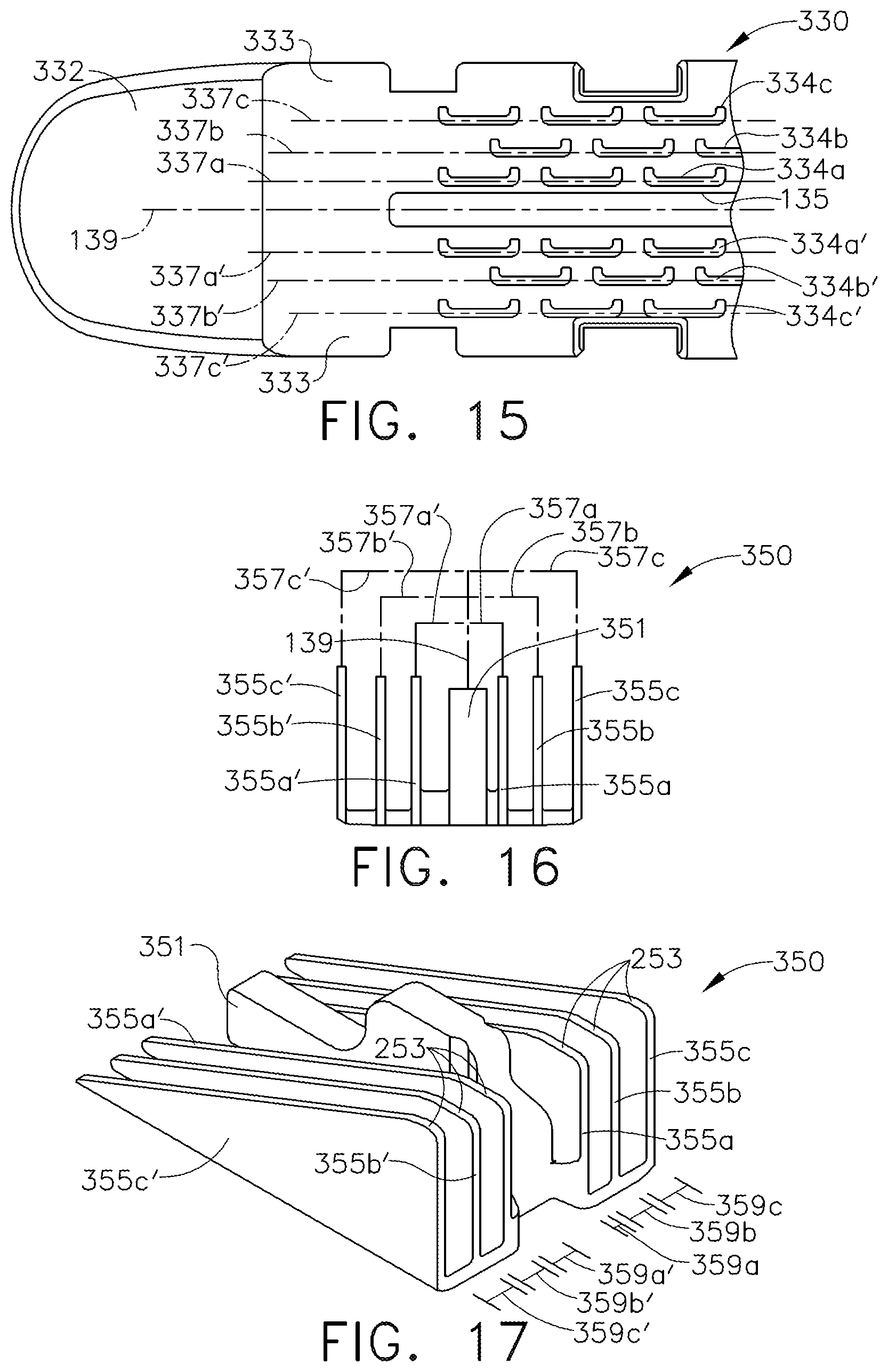
[0126] Turning now to FIGS. 15-19, a staple cartridge 330 comprises a cartridge body 332 including a deck 333 and a longitudinal slot 135 defined therein. The longitudinal slot 135 defines a longitudinal slot axis 139 extending through the center thereof. The staple cartridge 330 further comprises a first, or inner, longitudinal row of staple cavities 334a, a second, or intermediate, longitudinal row of staple cavities 334b, and a third, or outer, longitudinal row of staple cavities 334c on one side of the longitudinal slot 135. The staple cartridge 330 also comprises a first, or inner, longitudinal row of staple cavities 334a', a second, or intermediate, longitudinal row of staple cavities 334b', and a third, or outer, longitudinal row of staple cavities 334c' on the other side of the longitudinal slot 135. The staple cavities 334a, 334a', 334b, 334b', 334c, and 334c' are similar to the left-handed staple cavities 234a (FIGS. 4 and 6) in many respects. Staples 240 are removably stored in the staple cavities 334a, 334a', 334b, 334b', 334c, and 334c'.
[0127] Referring to FIGS. 16 and 17, the staple cartridge 330 further comprises a sled 350 configured to eject the staples 240 from the cartridge body 332. The sled 350 comprises a longitudinal ramp 355a configured to directly engage the staples 240 stored in the staple cavities 334a, a longitudinal ramp 355a' configured to directly engage the staples 240 stored in the staple cavities 334a', a longitudinal ramp 355b configured to directly engage the staples 240 stored in the staple cavities 334b, and a longitudinal ramp 355b' configured to directly engage the staples 240 stored in the staple cavities 334b'. The sled 350 further comprises a longitudinal ramp 355c configured to directly engage the staples 240 stored in the staple cavities 334c and a longitudinal ramp 355c' configured to directly engage the staples 240 stored in the staple cavities 334c'.
[0128] Further to the above, the staple cavities 334a are positioned along a longitudinal axis 337a, the staple cavities 334b are positioned along a longitudinal axis 337b, and the staple cavities 334c are positioned along a longitudinal axis 337c. Similarly, the staple cavities 334a' are positioned along a longitudinal axis 337a', the second staple cavities 334b' are positioned along a longitudinal axis 337b', and the staple cavities 334c' are positioned along a longitudinal axis 337c'. The distance between the longitudinal axis 337a and the longitudinal slot axis 139 is shorter than the distance between the longitudinal axis 337a' and the longitudinal slot axis 139. As a result, the longitudinal axis 337a' is staggered or offset laterally as compared to the longitudinal axis 337a. Similarly, the distance between the longitudinal row of staple cavities 334a and the longitudinal slot 135 is shorter than the distance between the longitudinal row of staple cavities 334a' and the longitudinal slot 135.
[0129] In addition, the distance between the longitudinal axis 337b and the longitudinal slot axis 139 is shorter than the distance between the longitudinal axis 337b' and the longitudinal slot axis 139. As a result, the longitudinal axis 337b' is staggered or offset laterally as compared to the longitudinal axis 337b. Similarly, the distance between the longitudinal row of staple cavities 334b and the longitudinal slot 135 is shorter than the distance between the longitudinal row of staple cavities 334b' and the longitudinal slot 135. Moreover, the distance between the longitudinal axis 337c and the longitudinal slot axis 139 is shorter than the distance between the longitudinal axis 337c' and the longitudinal slot axis 139. As a result, the longitudinal axis 337c' is staggered or offset laterally as compared to the longitudinal axis 337c. Similarly, the distance between the longitudinal row of staple cavities 334c and the longitudinal slot 135 is shorter than the distance between the longitudinal row of staple cavities 334c' and the longitudinal slot 135.
[0130] Further to the above, the longitudinal axes 337a, 337a', 337b, 337b', 337c, and 337c' comprise drive axes. These drive axes are aligned with the drive portions of the staples 240. The longitudinal ramps of the sled 350 are aligned with these drive axes. For instance, the longitudinal ramp 355a of the sled 350 is aligned with the longitudinal axis 337a. Similarly, the longitudinal ramp 355b is aligned with the longitudinal axis 337b and the longitudinal ramp 355c is aligned with the longitudinal axis 337c. Also, the longitudinal ramp 355a' is aligned with the longitudinal axis 337a', the longitudinal ramp 355b' is aligned with the longitudinal axis 337b', and the longitudinal ramp 355c' is aligned with the longitudinal axis 337c'. To this end, the longitudinal ramp 355a and the longitudinal axis 337a are a distance 357a away from the longitudinal slot axis 139, the longitudinal ramp 355b and the longitudinal axis 337b are a distance 357b away from the longitudinal slot axis 139, and the longitudinal ramp 355c and the longitudinal axis 337c are a distance 357c away from the longitudinal slot axis 139. Similarly, the longitudinal ramp 355a' and the longitudinal axis 337a' are a distance 357a' away from the longitudinal slot axis 139, the longitudinal ramp 355b' and the longitudinal axis 337b' are a distance 357b' away from the longitudinal slot axis 139, and the longitudinal ramp 355c' and the longitudinal axis 337c' are a distance 357c' away from the longitudinal slot axis 139.
[0131] Referring primarily to FIG. 17, the sled 350 comprises a central portion 351 configured to move within the longitudinal slot 135 of the cartridge body 332. The central portion 351 is sized and configured to be closely received within the slot 135 such that little, if any, lateral movement is permitted between the sled 350 and the cartridge body 332 so that the longitudinal ramps of the sled 350 remain properly aligned with the staples 240.
[0132] Referring again to FIG. 17, a gap 359a is defined between the central portion 351 of the sled 350 and the longitudinal ramp 355a. Similarly, a gap 359b is defined between the longitudinal ramp 355a and the longitudinal ramp 355b and a gap 359c is defined between the longitudinal ramp 355b and the longitudinal ramp 355c. The gap 359a is smaller than the gap 359b and, similarly, the gap 359b is smaller than the gap 359c. Likewise, a gap 359a' is defined between the central portion 351 of the sled 350 and the longitudinal ramp 355a'. Similarly, a gap 359b' is defined between the longitudinal ramp 355a' and the longitudinal ramp 355b' and a gap 359c' is defined between the longitudinal ramp 355b' and the longitudinal ramp 355c'. The gap 359a' is smaller than the gap 359b' and, similarly, the gap 359b' is smaller than the gap 359c'. Other arrangements are possible.
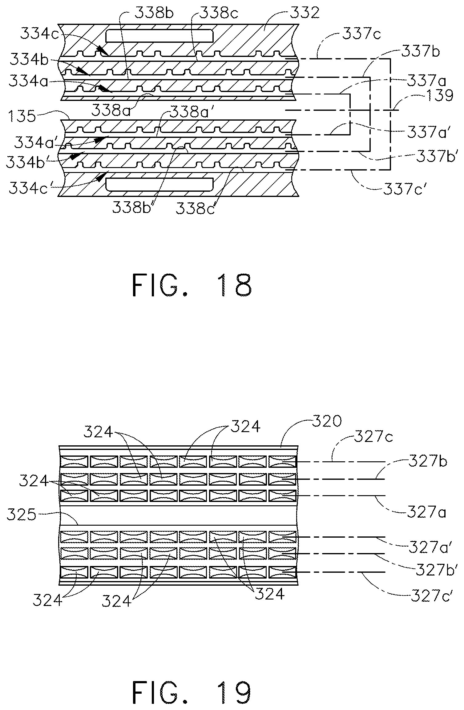
[0133] FIG. 18 is a cross-sectional view of the cartridge body 332 which illustrates longitudinal channels defined therein that connect the staple cavities in the staple cavity rows and permit the longitudinal ramps of the sled 350 to pass through the cartridge body 332. For instance, a channel 338a longitudinally connects the staple cavities 334a and is configured to receive the longitudinal ramp 355a of the sled 350. Similarly, a channel 338b longitudinally connects the staple cavities 334b and is configured to receive the longitudinal ramp 355b of the sled 350 and, in addition, a channel 338c longitudinally connects the staple cavities 334c and is configured to receive the longitudinal ramp 355c of the sled 350. Also, a channel 338a' longitudinally connects the staple cavities 334a' and is configured to receive the longitudinal ramp 355a' of the sled 350, a channel 338b' longitudinally connects the staple cavities 334b' and is configured to receive the longitudinal ramp 355b' of the sled 350, and a channel 338c' longitudinally connects the staple cavities 334c' and is configured to receive the longitudinal ramp 355c' of the sled 350.
[0134] Turning now to FIG. 19, an anvil 320 is configured to be used with the staple cartridge 330. The anvil 320 comprises forming pockets 324 configured to deform the staples 240 removably stored in the staple cartridge 330 when the staples 240 are ejected from the staple cartridge 330. The forming pockets 324 are arranged in six longitudinal rows which can be registered with the six longitudinal rows of staple cavities defined in the staple cartridge 330. For instance, a longitudinal row of forming pockets 324 is defined along a longitudinal anvil axis 327a which is alignable with the staple leg planes of the staples 240 stored in the longitudinal row of staple cavities 334a. Similarly, a longitudinal row of forming pockets 324 is defined along a longitudinal anvil axis 327b which is alignable with the staple leg planes of the staples 240 stored in the longitudinal row of staple cavities 334b and, in addition, a longitudinal row of forming pockets 324 is defined along a longitudinal anvil axis 327c which is alignable with the staple leg planes of the staples 240 stored in the longitudinal row of staple cavities 334c. Moreover, a longitudinal row of forming pockets 324 is defined along a longitudinal anvil axis 327a' which is alignable with the staple leg planes of the staples 240 stored in the longitudinal row of staple cavities 334a', a longitudinal row of forming pockets 324 is defined along a longitudinal anvil axis 327b' which is alignable with the staple leg planes of the staples 240 stored in the longitudinal row of staple cavities 334b', and a longitudinal row of forming pockets 324 is defined along a longitudinal anvil axis 327c' which is alignable with the staple leg planes of the staples 240 stored in the longitudinal row of staple cavities 334c'.
EXAMPLES
[0135] Example 1--A surgical stapling system comprising a shaft including a proximal end and a distal end, and an end effector extending from the distal end of the shaft, wherein the end effector is movable between an open configuration and a closed configuration. The end effector comprises a frame, an anvil extending distally from the frame, wherein the anvil comprises a longitudinal row of forming pockets, and a first staple cartridge assembly attachable to the end effector. The first staple cartridge assembly comprises a first cartridge body including a first longitudinal row of staple cavities and, in addition, a plurality of first staples removably stored in the first longitudinal row of staple cavities. Each first staple is comprised of a bent wire and is aligned with a forming pocket when the end effector is in the closed configuration. The surgical stapling system also comprises a second staple cartridge assembly attachable to the end effector in lieu of the first staple cartridge assembly. The second staple cartridge assembly comprises a second cartridge body including a second longitudinal row of staple cavities and, in addition, a plurality of second staples removably stored in the second longitudinal row of staple cavities. Each second staple is formed from flat stock and is aligned with a forming pocket when the end effector is in the closed configuration.
[0136] Example 2--The surgical stapling system of Example 1, wherein each forming pocket comprises a proximal forming cup and a distal forming cup.
[0137] Example 3--The surgical stapling system of Examples 1 and 2, wherein each first staple comprises a proximal leg formed by the proximal forming cup and a distal leg formed by the distal forming cup.
[0138] Example 4--The surgical stapling system of Examples 1, 2, and 3, wherein each second staple comprises a proximal leg formed by the proximal forming cup and a distal leg formed by the distal forming cup.
[0139] Example 5--The surgical stapling system of Examples 1, 2, 3, and 4, wherein the end effector further comprises a jaw configured to receive the first staple cartridge assembly and the second staple cartridge assembly in lieu of the first staple cartridge assembly.
[0140] Example 6--The surgical stapling system of Example 5, wherein the jaw is rotatable relative to the anvil to place the end effector in the closed configuration.
[0141] Example 7--The surgical stapling system of Examples 5 and 6, wherein the anvil is rotatable relative to the jaw to place the end effector in the closed configuration.
[0142] Example 8--The surgical stapling system of Example 1, wherein the first staple cartridge assembly comprises a first jaw attachable to the frame, and wherein the second cartridge assembly comprises a second jaw attachable to the frame.
[0143] Example 9--The surgical stapling system of Example 8, wherein the anvil is rotatable relative to the frame to place the end effector in the closed configuration.
[0144] Example 10--The surgical stapling system of Examples 8 and 9, wherein the first jaw is rotatable relative to the frame to place the end effector in the closed configuration when the first jaw is attached to the frame, and wherein the second jaw is rotatable relative to the frame to place the end effector in the closed configuration when the second jaw is attached to the frame.
[0145] Example 11--The surgical stapling system of Examples 1, 2, 3, 4, 5, 6, 7, 8, 9, and 10, wherein the first staple cartridge assembly comprises staple drivers configured to push the first staples out of the first staple cavities, and wherein each second staple comprises an integrally-formed staple driver.
[0146] Example 12--A surgical stapling system comprising a shaft including a proximal end and a distal end, and an end effector extending from the distal end of the shaft, wherein the end effector is movable between an unclamped configuration and a clamped configuration. The end effector comprises a frame, an anvil extending distally from the frame, wherein the anvil comprises a longitudinal row of forming pockets, and a first staple cartridge assembly attachable to the end effector. The first staple cartridge assembly comprises a first cartridge body including a first longitudinal row of staple cavities, and, in addition, a plurality of first staples removably stored in the first longitudinal row of staple cavities. Each first staple is comprised of a bent wire and is aligned with a forming pocket when the end effector is in the clamped configuration. The surgical stapling system also comprises a second staple cartridge assembly attachable to the end effector as an alternative to the first staple cartridge assembly. The second staple cartridge assembly comprises a second cartridge body including a second longitudinal row of staple cavities, and, in addition, a plurality of second staples removably stored in the second longitudinal row of staple cavities. The second staples are stamped from one or more flat sheets of material and are aligned with the forming pockets when the end effector is in the clamped configuration.
[0147] Example 13--The surgical stapling system of Example 12, wherein each forming pocket comprises a proximal forming cup and a distal forming cup.
[0148] Example 14--The surgical stapling system of Examples 12 and 13, wherein each first staple comprises a proximal leg formed by the proximal forming cup and a distal leg formed by the distal forming cup.
[0149] Example 15--The surgical stapling system of Examples 12, 13, and 14, wherein each second staple comprises a proximal leg formed by the proximal forming cup and a distal leg formed by the distal forming cup.
[0150] Example 16--The surgical stapling system of Examples 12, 13, 14, and 15, wherein the end effector further comprises a jaw configured to receive the first staple cartridge assembly and the second staple cartridge assembly as an alternative to the first staple cartridge assembly.
[0151] Example 17--The surgical stapling system of Example 16, wherein the jaw is rotatable relative to the anvil to place the end effector in the clamped configuration.
[0152] Example 18--The surgical stapling system of Examples 16 and 17, wherein the anvil is rotatable relative to the jaw to place the end effector in the clamped configuration.
[0153] Example 19--The surgical stapling system of Example 12, wherein the first staple cartridge assembly comprises a first jaw attachable to the frame, and wherein the second cartridge assembly comprises a second jaw attachable to the frame.
[0154] Example 20--The surgical stapling system of Example 19, wherein the anvil is rotatable relative to the frame to place the end effector in the clamped configuration.
[0155] Example 21--The surgical stapling system of Examples 19 and 20, wherein the first jaw is rotatable relative to the frame to place the end effector in the clamped configuration when the first jaw is attached to the frame, and wherein the second jaw is rotatable relative to the frame to place the end effector in the clamped configuration when the second jaw is attached to the frame.
[0156] Example 22--The surgical stapling system of Examples 12, 13, 14, 15, 16, 17, 18, 19, 20, and 21, wherein the first staple cartridge assembly comprises staple drivers configured to push the first staples out of the first staple cavities, and wherein the second staple comprises an integrally-formed staple driver.
[0157] Example 23--A surgical fastening system comprising a shaft including a proximal end and a distal end, and an end effector extending from the distal end of the shaft, wherein the end effector is movable between an open configuration and a closed configuration. The end effector comprises a frame and an anvil extending distally from the frame, wherein the anvil comprises forming pockets. The surgical fastening system further comprises a first fastener cartridge assembly attachable to the end effector. The first fastener cartridge assembly comprises a first cartridge body including first fastener cavities and, in addition, a plurality of first fasteners removably stored in the first fastener cavities. Each first fastener is comprised of a bent wire, and the first fastener cavities are aligned with the forming pockets when the end effector is in the closed configuration. The surgical fastening system also comprises a second fastener cartridge assembly attachable to the end effector in lieu of the first fastener cartridge assembly, wherein the second fastener cartridge assembly comprises a second cartridge body including second fastener cavities and, in addition, a plurality of second fasteners removably stored in the second fastener cavities. Each second fastener is formed from flat stock, and the second fastener cavities are aligned with the forming pockets when the end effector is in the closed configuration.
[0158] Example 24--A staple cartridge assembly comprising a cartridge body including a proximal end, a distal end, and staple cavities extending between the proximal end and the distal end, and, in addition, staples removably stored in the staple cavities, wherein each the staple is formed from flat stock. Each staple comprises a crown, a proximal leg, a distal leg, wherein the proximal leg and the distal leg define a staple leg plane, and an inclined cam surface extending from and integrally formed with the crown, wherein the inclined cam surface defines a cam plane which is different than the staple leg plane. Each staple also comprises a proximal connector which extends between and is integrally formed with the proximal leg and the crown and a distal connector which extends between and is integrally formed with the distal leg and the crown, wherein the inclined cam surface does not extend from the proximal connector, and wherein the inclined cam surface does not extend from the distal connector. The staple cartridge assembly also comprises a sled configured to engage the inclined cam surfaces of the staples and eject the staples from the staple cavities during a staple firing stroke.
[0159] Example 25--The staple cartridge assembly of Example 24, wherein the inclined cam surface is planar, and wherein the proximal connector and the distal connector bend out of the cam plane toward the staple leg plane.
[0160] Example 26--The staple cartridge assembly of Examples 24 and 25, wherein the inclined cam surface comprises a proximal lead-in in the cam plane.
[0161] Example 27--The staple cartridge assembly of Examples 24, 25, and 26, wherein each staple further comprises a clearance notch between the proximal lead-in and the proximal connector, and wherein the clearance notch is defined in the cam plane.
[0162] Example 28--The staple cartridge assembly of Examples 24, 25, 26, and 27, wherein the proximal leg and the distal leg of each staple extend outwardly in non-parallel directions from the crown when the staples are in an unfired configuration.
[0163] Example 29--The staple cartridge assembly of Examples 24, 25, 26, 27, and 28, wherein the proximal and distal legs of the staples are flexed inwardly by the sidewalls of the staple cavities when the staples are stored in the staple cavities.
[0164] Example 30--The staple cartridge assembly of Examples 24, 25, 26, 27, 28, and 29, wherein the sled does not engage the proximal connectors and the distal connectors of the staples during the staple firing stroke.
[0165] Example 31--The staple cartridge assembly of Examples 24, 25, 26, 27, 28, 29, and 30, wherein the entirety of the inclined cam surface is positioned below the proximal staple leg and the distal staple leg.
[0166] Example 32--The staple cartridge assembly of Examples 24, 25, 26, 27, 28, 29, 30, and 31, wherein the inclined cam surface comprises an initial pick-up point for the sled.
[0167] Example 33--A staple cartridge assembly, comprising a cartridge body including a proximal end, a distal end, staple cavities extending between the proximal end and the distal end, and, in addition, staples removably stored in the staple cavities, wherein the staples are formed from one or more metal sheets. Each staple comprises a crown, a proximal leg, a distal leg, and a cam surface extending from and integrally formed with the crown, wherein the cam surface defines a cam plane, and wherein the proximal leg and the distal leg are not in the cam plane. Each staple also comprises a proximal connector which extends between and is integrally formed with the proximal leg and the crown and a distal connector which extends between and is integrally formed with the distal leg and the crown, wherein the cam surface does not extend from the proximal connector. The staple cartridge assembly also comprises a sled configured to engage the cam surfaces of the staples and eject the staples from the staple cavities during a staple firing stroke.
[0168] Example 34--The staple cartridge assembly of Example 33, wherein the cam surface is planar, and wherein the proximal connector and the distal connector bend out of the cam plane.
[0169] Example 35--The staple cartridge assembly of Examples 33 and 34, wherein the cam surface comprises a proximal lead-in in the cam plane.
[0170] Example 36--The staple cartridge assembly of Examples 33, 34, and 35, wherein each staple further comprises a clearance notch between the proximal lead-in and the proximal connector, and wherein the clearance notch is defined in the cam plane.
[0171] Example 37--The staple cartridge assembly of Examples 33, 34, 35, and 36, wherein the proximal leg and the distal leg of each staple extend outwardly in non-parallel directions from the crown when the staples are in an unfired configuration.
[0172] Example 38--The staple cartridge assembly of Examples 33, 34, 35, 36, and 37, wherein the proximal and distal legs of the staples are flexed inwardly by the sidewalls of the staple cavities when the staples are stored in the staple cavities.
[0173] Example 39--The staple cartridge assembly of Examples 33, 34, 35, 36, 37, and 38, wherein the sled does not engage the proximal connectors of the staples during the staple firing stroke.
[0174] Example 40--The staple cartridge assembly of Examples 33, 34, 35, 36, 37, 38, and 39, wherein the entirety of the cam surface is positioned below the proximal staple leg and the distal staple leg.
[0175] Example 41--The staple cartridge assembly of Examples 33, 34, 35, 36, 37, 38, 39, and 40, wherein the cam surface comprises an initial pick-up point for the sled.
[0176] Example 42--A staple cartridge assembly comprising a cartridge body including a deck comprising a proximal end and a distal end, a longitudinal slot defined in the deck, wherein the longitudinal slot is configured to receive a firing member, a first longitudinal row of staple cavities, and a second longitudinal row of staple cavities. The staple cartridge assembly further comprises a sled movable toward the distal end by the firing member during a firing stroke and a plurality of first staples removably stored in the first longitudinal row of staple cavities, wherein each first staple is comprised of a bent wire. The staple cartridge assembly also comprises a plurality of staple drivers configured to support the first staples, wherein the sled is configured to engage the staple drivers to eject the first staples from the first longitudinal row of staple cavities during the firing stroke, and a plurality of second staples removably stored in the second longitudinal row of staple cavities, wherein each second staple is formed from flat stock and comprises an integrally-formed driver, and wherein the sled is configured to directly engage the integrally-formed drivers of the second staples and eject the second staples from the second longitudinal row of staple cavities during the firing stroke.
[0177] Example 43--The staple cartridge assembly of Example 42, wherein the first longitudinal row of staple cavities is adjacent the longitudinal slot, and wherein the first longitudinal row of staple cavities is intermediate the longitudinal slot and the second longitudinal row of staple cavities.
[0178] Example 44--The staple cartridge assembly of Example 42, wherein the second longitudinal row of staple cavities is adjacent the longitudinal slot, and wherein the second longitudinal row of staple cavities is intermediate the longitudinal slot and the first longitudinal row of staple cavities.
[0179] Example 45--The staple cartridge assembly of Examples 42, 43, and 44, wherein the cartridge body further comprises a third longitudinal row of staple cavities, wherein the staple cartridge assembly further comprises a plurality of third staples removably stored in the third longitudinal row of staple cavities, and wherein each third staple is comprised of a bent wire.
[0180] Example 46--The staple cartridge assembly of Example 45, wherein the third longitudinal row of staple cavities is adjacent the first longitudinal row of staple cavities, wherein the staple drivers are configured to support the third staples, and wherein the sled is configured to engage the staple drivers to eject the third staples from the third longitudinal row of staple cavities during the firing stroke.
[0181] Example 47--The staple cartridge assembly of Examples 45, further comprising a plurality of staple drivers configured to support the third staples and be engaged by the sled to eject the third staples from the third longitudinal row of staple cavities during the firing stroke.
[0182] Example 48--The staple cartridge assembly of Examples 42, 43, and 44, wherein the cartridge body further comprises a third longitudinal row of staple cavities, wherein the staple cartridge assembly further comprises a plurality of third staples removably stored in the third longitudinal row of staple cavities, wherein each third staple is formed from flat stock and comprises an integrally-formed driver, and wherein the sled is configured to directly engage the integrally-formed drivers of the third staples and eject the third staples from the third longitudinal row of staple cavities during the firing stroke.
[0183] Example 49--The staple cartridge assembly of Example 48, wherein the third longitudinal row of staple cavities is adjacent the longitudinal slot, wherein the second longitudinal row of staple cavities is adjacent the third longitudinal row of staple cavities, and wherein the second longitudinal row of staple cavities is intermediate the first longitudinal row of staple cavities and the third longitudinal row of staple cavities.
[0184] Example 50--A staple cartridge assembly comprising a cutting member and a cartridge body, wherein the cartridge body includes a deck comprising a proximal end and a distal end, a longitudinal slot defined in the deck, wherein the longitudinal slot is configured to receive the cutting member, a first longitudinal row of staple cavities, and a second longitudinal row of staple cavities. The staple cartridge assembly further comprises a sled movable toward the distal end by the cutting member during a firing stroke and a plurality of first staples removably stored in the first longitudinal row of staple cavities, wherein each first staple is comprised of a bent wire. The staple cartridge assembly also comprises a plurality of staple drivers configured to support the first staples, wherein the sled is configured to engage the staple drivers to eject the first staples from the first longitudinal row of staple cavities during the firing stroke, and, in addition, a plurality of second staples removably stored in the second longitudinal row of staple cavities, wherein the second staples are stamped from one or more metal sheets, and wherein the sled is configured to directly engage the second staples and eject the second staples from the second longitudinal row of staple cavities during the firing stroke.
[0185] Example 51--The staple cartridge assembly of Example 50, wherein the first longitudinal row of staple cavities is adjacent the longitudinal slot, and wherein the first longitudinal row of staple cavities is intermediate the longitudinal slot and the second longitudinal row of staple cavities.
[0186] Example 52--The staple cartridge assembly of Example 50, wherein the second longitudinal row of staple cavities is adjacent the longitudinal slot, and wherein the second longitudinal row of staple cavities is intermediate the longitudinal slot and the first longitudinal row of staple cavities.
[0187] Example 53--The staple cartridge assembly of Examples 50, 51, and 52, wherein the cartridge body further comprises a third longitudinal row of staple cavities, wherein the staple cartridge assembly further comprises a plurality of third staples removably stored in the third longitudinal row of staple cavities, and wherein each third staple is comprised of a bent wire.
[0188] Example 54--The staple cartridge assembly of Example 53, wherein the third longitudinal row of staple cavities is adjacent the first longitudinal row of staple cavities, wherein the staple drivers are configured to support the third staples, and wherein the sled is configured to engage the staple drivers to eject the third staples from the third longitudinal row of staple cavities during the firing stroke.
[0189] Example 55--The staple cartridge assembly of Example 53, further comprising a plurality of staple drivers configured to support the third staples and be engaged by the sled to eject the third staples from the third longitudinal row of staple cavities during the firing stroke.
[0190] Example 56--The staple cartridge assembly of Examples 50, 51, 52, 53, 54, and 55, wherein the cartridge body further comprises a third longitudinal row of staple cavities, wherein the staple cartridge assembly further comprises a plurality of third staples removably stored in the third longitudinal row of staple cavities, wherein the third staples are formed from one or more metal sheets, and wherein the sled is configured to directly engage the third staples and eject the third staples from the third longitudinal row of staple cavities during the firing stroke.
[0191] Example 57--The staple cartridge assembly of Examples 50, 51, and 52, wherein the third longitudinal row of staple cavities is adjacent the longitudinal slot, wherein the second longitudinal row of staple cavities is adjacent the third longitudinal row of staple cavities, and wherein the second longitudinal row of staple cavities is intermediate the first longitudinal row of staple cavities and the third longitudinal row of staple cavities.
[0192] Example 58--A staple cartridge assembly comprising a cartridge body including a deck comprising a proximal end and a distal end, a longitudinal slot defined in the deck, wherein the longitudinal slot is configured to receive a firing member, and a plurality of staple cavities. The staple cartridge assembly further comprises a sled movable toward the distal end by the firing member during a firing stroke, a plurality of first staples removably stored in the staple cavities, wherein each first staple is comprised of a bent wire, and, in addition, a plurality of staple drivers, wherein the sled is configured to engage the staple drivers to eject the first staples from the staple cavities during the firing stroke. The staple cartridge assembly also comprises a plurality of second staples removably stored in the staple cavities, wherein each second staple is formed from flat stock and comprises an integrally-formed driver, and wherein the sled is configured to directly engage the integrally-formed drivers of the second staples and eject the second staples from the staple cavities during the firing stroke.
[0193] Example 59--A staple cartridge assembly comprising a cartridge body including a proximal end, a distal end, a deck configured to support the tissue of a patient, and a plurality of staple cavities defined in the deck. The staple cartridge assembly also comprises a plurality of metal staples removably stored in the staple cavities, wherein each metal staple comprises a crown comprising a tissue contacting surface, a first leg connected to the crown, a second leg connected to the crown, and a driver integrally formed with the crown. In addition, the staple cartridge assembly comprises a sled movable toward the distal end during a firing stroke, wherein the sled is configured to directly engage the drivers of the metal staples and move each metal staple between an unfired position and a fired position during the firing stroke, wherein the tissue contacting surfaces of the crowns are positioned above the deck when the metal staples are in the fired position, and wherein the drivers of the metal staples are positioned at least partially below the deck when the metal staples are in the fired position.
[0194] Example 60--The staple cartridge assembly of Example 59, wherein the cartridge body further comprises guides extending from the deck which are configured to support and guide the staple legs above the deck as the metal staples are moved into the fired position, and wherein the tissue contacting surfaces of the crowns are at least partially positioned above the guides when the metal staples are in the fired position.
[0195] Example 61--The staple cartridge assembly of Examples 59 and 60, wherein the sled comprises one or more drive surfaces configured to engage the drivers of the metal staples, wherein each drive surface comprises a top surface, and wherein the top surface of each drive surface is entirely below the deck.
[0196] Example 62--A staple cartridge assembly comprising a cartridge body including a proximal end, a distal end, a deck configured to support the tissue of a patient, and a staple cavity defined in the deck. The staple cartridge assembly further comprises a staple removably stored in the staple cavity, wherein the staple includes a crown comprising a tissue engaging surface, a first leg extending from the crown, a second leg extending from the crown, and a driver integrally formed with the crown. In addition, the staple cartridge assembly comprises a sled movable toward the distal end during a firing stroke, wherein the sled is configured to directly engage the driver of the staple and move the staple between an unfired position and a fired position during the firing stroke, wherein the tissue engaging surface of the crown is positioned at least partially above the deck when the staple is in the fired position, and wherein the driver is positioned at least partially below the deck when the staple is in the fired position.
[0197] Example 63--The staple cartridge assembly of Example 62, wherein the cartridge body further comprises a guide extending from the deck which is configured to support and guide the first staple leg above the deck as the staple is moved into the fired position, and wherein the tissue contacting surface of the crown is at least partially positioned above the guide when the staple is in the fired position.
[0198] Example 64--The staple cartridge assembly of Examples 62 and 63, wherein the sled comprises a drive surface configured to engage the driver of the staple, wherein the drive surface comprises a top surface, and wherein the top surface is entirely below the deck.
[0199] Example 65--A staple cartridge assembly comprising a cartridge body including a proximal end, a distal end, a deck configured to support the tissue of a patient, and a staple cavity defined in the deck. The staple cartridge assembly further comprises a staple removably stored in the staple cavity, wherein the staple includes a crown comprising a tissue engaging surface, a first leg extending from the crown, a second leg extending from the crown, and a driver integrally formed with the crown. The staple cartridge assembly also comprises a firing member movable toward the distal end during a firing stroke, wherein the firing member is configured to directly engage the driver of the staple and move the staple between an unfired position and a fired position during the firing stroke, wherein the tissue engaging surface of the crown is positioned entirely above the deck when the staple is in the fired position, and wherein the driver is positioned entirely below the deck when the staple is in the fired position.
[0200] Example 66--The staple cartridge assembly of Example 65, wherein the cartridge body further comprises a guide extending from the deck which is configured to support and guide the first staple leg above the deck as the staple is moved into the fired position, and wherein the tissue contacting surface of the crown is entirely partially positioned above the guide when the staple is in the fired position.
[0201] Example 67--The staple cartridge assembly of Examples 65 and 66, wherein the firing member comprises a drive surface configured to engage the driver of the staple, wherein the drive surface comprises a top surface, and wherein the top surface is entirely below the deck.
[0202] Example 68--A staple cartridge assembly comprising a cartridge body, including a deck configured to support the tissue of a patient, a longitudinal slot defined in the deck, wherein the longitudinal slot defines a longitudinal slot axis, wherein the longitudinal slot is configured to receive a cutting member, and wherein the deck comprises a first deck portion on a first side of the longitudinal slot and a second deck portion on a second side of the longitudinal slot. The cartridge body further comprises a first row of staple cavities defined in the first deck portion adjacent the longitudinal slot, wherein the first row of staple cavities is defined along a first longitudinal axis, and wherein a first distance is defined between the first longitudinal axis and the longitudinal slot axis. The cartridge body also comprises a second row of staple cavities defined in the second deck portion adjacent the longitudinal slot, wherein the second row of staple cavities is defined along a second longitudinal axis, wherein a second distance is defined between the second longitudinal axis and the longitudinal slot axis, and wherein the second distance is different than the first distance. The staple cartridge assembly further comprises staples removably stored in the first row of staple cavities and the second row of staple cavities.
[0203] Example 69--The staple cartridge assembly of Example 68, further comprising a sled, wherein the sled comprises a first longitudinal ramp configured to eject the staples from the first row of staple cavities and a second longitudinal ramp configured to eject the staples from the second row of staple cavities.
[0204] Example 70--The staple cartridge assembly of Example 69, wherein the first distance is defined between the first longitudinal ramp and the longitudinal slot axis, and wherein the second distance is defined between the second longitudinal ramp and the longitudinal slot axis.
[0205] Example 71--A fastener cartridge assembly comprising a cartridge body including a deck configured to support the tissue of a patient and a longitudinal slot defined in the deck, wherein the longitudinal slot defines a longitudinal slot axis, wherein the longitudinal slot is configured to receive a cutting member, and wherein the deck comprises a first deck portion on a first side of the longitudinal slot and a second deck portion on a second side of the longitudinal slot. The cartridge body further comprises a first row of fastener cavities defined in the first deck portion adjacent to the longitudinal slot, wherein the first row of fastener cavities is defined along a first longitudinal axis, and wherein a first distance is defined between the first longitudinal axis and the longitudinal slot axis. The cartridge body also comprises a second row of fastener cavities defined in the second deck portion adjacent the longitudinal slot, wherein the second row of fastener cavities is defined along a second longitudinal axis, wherein a second distance is defined between the second longitudinal axis and the longitudinal slot axis, and wherein the second distance is different than the first distance. The fastener cartridge assembly further comprises fasteners removably stored in the first row of fastener cavities and the second row of fastener cavities, wherein the fasteners are formed from one or more sheets of material.
[0206] Example 72--The fastener cartridge assembly of Example 71, wherein the first row of fastener cavities is closer to the longitudinal slot than the second row of fastener cavities.
[0207] Example 73--The fastener cartridge assembly of Example 71, wherein the second row of fastener cavities is closer to the longitudinal slot than the first row of fastener cavities.
[0208] Example 74--The fastener cartridge assembly of Examples 71, 72, and 73, further comprising a sled, wherein the sled comprises a first longitudinal ramp configured to eject the fasteners from the first row of fastener cavities and a second longitudinal ramp configured to eject the fasteners from the second row of fastener cavities.
[0209] Example 75--The fastener cartridge assembly of Example 74, wherein the first longitudinal ramp is positioned closer to the longitudinal slot than the second longitudinal ramp.
[0210] Example 76--The fastener cartridge assembly of Example 74, wherein the second longitudinal ramp is positioned closer to the longitudinal slot than the first longitudinal ramp.
[0211] Example 77--A staple cartridge assembly comprising a cartridge body including a deck configured to support the tissue of a patient and a longitudinal slot defined in the deck, wherein the longitudinal slot is configured to receive a cutting member, and wherein the deck comprises a first deck portion on a first side of the longitudinal slot and a second deck portion on a second side of the longitudinal slot. The cartridge body further comprises a first row of staple cavities defined in the first deck portion adjacent the longitudinal slot, and wherein a first distance is defined between the first row of staple cavities and the longitudinal slot. The cartridge body also comprises a second row of staple cavities defined in the second deck portion adjacent the longitudinal slot, and wherein a second distance is defined between the second row of staple cavities and the longitudinal slot, and wherein the second distance is different than the first distance. The staple cartridge assembly further comprises staples removably stored in the first row of staple cavities and the second row of staple cavities.
[0212] Example 78--The staple cartridge assembly of Example 77, further comprising a sled, wherein the sled includes a first longitudinal ramp configured to eject the staples from the first row of staple cavities and a second longitudinal ramp configured to eject the staples from the second row of staple cavities.
[0213] Example 79--The staple cartridge assembly of Example 78, wherein the first distance is defined between the first longitudinal ramp and the longitudinal slot, and wherein the second distance is defined between second longitudinal ramp and the longitudinal slot.
[0214] Example 80--The staple cartridge assembly of Examples 78 and 79, wherein each staple comprises a crown, a cam portion integrally formed with the crown, wherein the sled is configured to directly engage the cam portion, and a tissue clenching portion offset from the cam portion.
[0215] Example 81--The staple cartridge assembly of Example 80, wherein the cam portions of the staples are positioned closer to the longitudinal slot than the tissue clenching portions.
[0216] Example 82--The staple cartridge assembly of Example 80, wherein the tissue clenching portions of the staples are positioned closer to the longitudinal slot than the cam portions.
[0217] Example 83--The staple cartridge assembly of Examples 77, 78, 79, 80, 81, and 82, wherein the first distance is shorter than the second distance.
[0218] Example 84--The staple cartridge assembly of Examples 77, 78, 79, 80, 81, and 82, wherein the second distance is shorter than the first distance.
[0219] The surgical instrument systems described herein have been described in connection with the deployment and deformation of staples; however, the embodiments described herein are not so limited. Various embodiments are envisioned which deploy fasteners other than staples, such as clamps or tacks, for example. Moreover, various embodiments are envisioned which utilize any suitable means for sealing tissue. For instance, an end effector in accordance with various embodiments can comprise electrodes configured to heat and seal the tissue. Also, for instance, an end effector in accordance with certain embodiments can apply vibrational energy to seal the tissue.
[0220] The entire disclosures of:
[0221] U.S. patent application Ser. No. 14/822,970, entitled ADAPTER ASSEMBLY FOR INTERCONNECTING ELECTROMECHANICAL SURGICAL DEVICES AND SURGICAL LOADING UNITS, AND SURGICAL SYSTEMS THEREOF, filed on Aug. 11, 2015, now U.S. Pat. No. 10,123,799;
[0222] U.S. patent application Ser. No. 13/921,890, entitled APPARATUS FOR ENDOSCOPIC PROCEDURES, filed on Jun. 19, 2013, now U.S. Pat. No. 9,480,492;
[0223] U.S. patent application Ser. No. 13/924,054, entitled SURGICAL STAPLING APPARATUS, filed on Jun. 21, 2013, now U.S. Pat. No. 9,668,729;
[0224] U.S. patent application Ser. No. 14/257,063, entitled ADAPTER ASSEMBLY WITH GIMBAL FOR INTERCONNECTING ELECTROMECHANICAL SURGICAL DEVICES AND SURGICAL LOADING UNITS, AND SURGICAL SYSTEMS THEREOF, filed Apr. 21, 2014, now U.S. Pat. No. 10,080,552;
[0225] U.S. patent application Ser. No. 14/674,152, entitled DISPOSABLE HOUSINGS FOR ENCASING HANDLE ASSEMBLIES AND METHODS OF USE, filed Mar. 31, 2015, now U.S. Pat. No. 9,987,099;
[0226] U.S. patent application Ser. No. 14/672,973, entitled ADAPTER ASSEMBLY FOR INTERCONNECTING ELECTROMECHANICAL SURGICAL DEVICES AND SURGICAL LOADING UNITS, AND SURGICAL SYSTEMS THEREOF, filed Mar. 30, 2015, now U.S. Pat. No. 9,839,425;
[0227] U.S. patent application Ser. No. 14/672,731, entitled ADAPTER ASSEMBLIES FOR INTERCONNECTING ELECTROMECHANICAL HANDLE ASSEMBLIES AND SURGICAL LOADING UNITS, filed Mar. 30, 2015, now U.S. Pat. No. 9,987,095; and
[0228] European Patent Application Publication No. EP 3005956 A1, entitled STAPLE CARTRIDGE WITH SHIPPING WEDGE, which published on Apr. 13, 2016; and
[0229] PCT Publication No. WO 2016/057225 A1, entitled HANDHELD ELECTROMECHANICAL SURGICAL SYSTEM, which published on Apr. 14, 2016, are hereby incorporated by reference herein.
[0230] The entire disclosures of:
[0231] European Patent Application No. EP 795298, entitled LINEAR STAPLER WITH IMPROVED FIRING STROKE, which was filed on Mar. 12, 1997;
[0232] U.S. Pat. No. 5,605,272, entitled TRIGGER MECHANISM FOR SURGICAL INSTRUMENTS, which issued on Feb. 25, 1997;
[0233] U.S. Pat. No. 5,697,543, entitled LINEAR STAPLER WITH IMPROVED FIRING STROKE, which issued on Dec. 16, 1997;
[0234] U.S. Patent Application Publication No. 2005/0246881, entitled METHOD FOR MAKING A SURGICAL STAPLER, which published on Nov. 10, 2005;
[0235] U.S. Patent Application Publication No. 2007/0208359, entitled METHOD FOR STAPLING TISSUE, which published on Sep. 6, 2007;
[0236] U.S. Pat. No. 4,527,724, entitled DISPOSABLE LINEAR SURGICAL STAPLING INSTRUMENT, which issued on Jul. 9, 1985;
[0237] U.S. Pat. No. 5,137,198, entitled FAST CLOSURE DEVICE FOR LINEAR SURGICAL STAPLING INSTRUMENT, which issued on Aug. 11, 1992;
[0238] U.S. Pat. No. 5,405,073, entitled FLEXIBLE SUPPORT SHAFT ASSEMBLY, which issued on Apr. 11, 1995;
[0239] U.S. Pat. No. 8,360,297, entitled SURGICAL CUTTING AND STAPLING INSTRUMENT WITH SELF ADJUSTING ANVIL, which issued on Jan. 29, 2013;
[0240] U.S. patent application Ser. No. 14/813,242, entitled SURGICAL INSTRUMENT COMPRISING SYSTEMS FOR ASSURING THE PROPER SEQUENTIAL OPERATION OF THE SURGICAL INSTRUMENT, which was filed on Jul. 30, 2015, now U.S. Pat. No. 10,194,913;
[0241] U.S. patent application Ser. No. 14/813,259, entitled SURGICAL INSTRUMENT COMPRISING SEPARATE TISSUE SECURING AND TISSUE CUTTING SYSTEMS, which was filed on Jul. 30, 2015, now U.S. Patent Application Publication No. 2017/0027572;
[0242] U.S. patent application Ser. No. 14/813,266, entitled SURGICAL INSTRUMENT COMPRISING SYSTEMS FOR PERMITTING THE OPTIONAL TRANSECTION OF TISSUE, which was filed on Jul. 30, 2015, now U.S. Pat. No. 10,524,795;
[0243] U.S. patent application Ser. No. 14/813,274, entitled SURGICAL INSTRUMENT COMPRISING A SYSTEM FOR BYPASSING AN OPERATIONAL STEP OF THE SURGICAL INSTRUMENT; which was filed on Jul. 30, 2015, now U.S. Pat. No. 10,420,558;
[0244] U.S. Pat. No. 5,403,312, entitled ELECTROSURGICAL HEMOSTATIC DEVICE, which issued on Apr. 4, 1995;
[0245] U.S. Pat. No. 7,000,818, entitled SURGICAL STAPLING INSTRUMENT HAVING SEPARATE DISTINCT CLOSING AND FIRING SYSTEMS, which issued on Feb. 21, 2006;
[0246] U.S. Pat. No. 7,422,139, entitled MOTOR-DRIVEN SURGICAL CUTTING AND FASTENING INSTRUMENT WITH TACTILE POSITION FEEDBACK, which issued on Sep. 9, 2008;
[0247] U.S. Pat. No. 7,464,849, entitled ELECTRO-MECHANICAL SURGICAL INSTRUMENT WITH CLOSURE SYSTEM AND ANVIL ALIGNMENT COMPONENTS, which issued on Dec. 16, 2008;
[0248] U.S. Pat. No. 7,670,334, entitled SURGICAL INSTRUMENT HAVING AN ARTICULATING END EFFECTOR, which issued on Mar. 2, 2010;
[0249] U.S. Pat. No. 7,753,245, entitled SURGICAL STAPLING INSTRUMENTS, which issued on Jul. 13, 2010;
[0250] U.S. Pat. No. 8,393,514, entitled SELECTIVELY ORIENTABLE IMPLANTABLE FASTENER CARTRIDGE, which issued on Mar. 12, 2013;
[0251] U.S. patent application Ser. No. 11/343,803, entitled SURGICAL INSTRUMENT HAVING RECORDING CAPABILITIES, now U.S. Pat. No. 7,845,537;
[0252] U.S. patent application Ser. No. 12/031,573, entitled SURGICAL CUTTING AND FASTENING INSTRUMENT HAVING RF ELECTRODES, filed Feb. 14, 2008;
[0253] U.S. patent application Ser. No. 12/031,873, entitled END EFFECTORS FOR A SURGICAL CUTTING AND STAPLING INSTRUMENT, filed Feb. 15, 2008, now U.S. Pat. No. 7,980,443;
[0254] U.S. patent application Ser. No. 12/235,782, entitled MOTOR-DRIVEN SURGICAL CUTTING INSTRUMENT, now U.S. Pat. No. 8,210,411;
[0255] U.S. patent application Ser. No. 12/249,117, entitled POWERED SURGICAL CUTTING AND STAPLING APPARATUS WITH MANUALLY RETRACTABLE FIRING SYSTEM, now U.S. Pat. No. 8,608,045;
[0256] U.S. patent application Ser. No. 12/647,100, entitled MOTOR-DRIVEN SURGICAL CUTTING INSTRUMENT WITH ELECTRIC ACTUATOR DIRECTIONAL CONTROL ASSEMBLY, filed Dec. 24, 2009, now U.S. Pat. No. 8,220,688;
[0257] U.S. patent application Ser. No. 12/893,461, entitled STAPLE CARTRIDGE, filed Sep. 29, 2012, now U.S. Pat. No. 8,733,613;
[0258] U.S. patent application Ser. No. 13/036,647, entitled SURGICAL STAPLING INSTRUMENT, filed Feb. 28, 2011, now U.S. Pat. No. 8,561,870;
[0259] U.S. patent application Ser. No. 13/118,241, entitled SURGICAL STAPLING INSTRUMENTS WITH ROTATABLE STAPLE DEPLOYMENT ARRANGEMENTS, now U.S. Pat. No. 9,072,535;
[0260] U.S. patent application Ser. No. 13/524,049, entitled ARTICULATABLE SURGICAL INSTRUMENT COMPRISING A FIRING DRIVE, filed on Jun. 15, 2012, now U.S. Pat. No. 9,101,358;
[0261] U.S. patent application Ser. No. 13/800,025, entitled STAPLE CARTRIDGE TISSUE THICKNESS SENSOR SYSTEM, filed on Mar. 13, 2013, now U.S. Pat. No. 9,345,481;
[0262] U.S. patent application Ser. No. 13/800,067, entitled STAPLE CARTRIDGE TISSUE THICKNESS SENSOR SYSTEM, filed on Mar. 13, 2013, now U.S. Patent Application Publication No. 2014/0263552;
[0263] U.S. Patent Application Publication No. 2007/0175955, entitled SURGICAL CUTTING AND FASTENING INSTRUMENT WITH CLOSURE TRIGGER LOCKING MECHANISM, filed Jan. 31, 2006; and
[0264] U.S. Patent Application Publication No. 2010/0264194, entitled SURGICAL STAPLING INSTRUMENT WITH AN ARTICULATABLE END EFFECTOR, filed Apr. 22, 2010, now U.S. Pat. No. 8,308,040, are hereby incorporated by reference herein.
[0265] Although various devices have been described herein in connection with certain embodiments, modifications and variations to those embodiments may be implemented. Also, where materials are disclosed for certain components, other materials may be used. Furthermore, according to various embodiments, a single component may be replaced by multiple components, and multiple components may be replaced by a single component, to perform a given function or functions. The foregoing description and following claims are intended to cover all such modification and variations.
[0266] The devices disclosed herein can be designed to be disposed of after a single use, or they can be designed to be used multiple times. In either case, however, a device can be reconditioned for reuse after at least one use. Reconditioning can include any combination of the steps including, but not limited to, the disassembly of the device, followed by cleaning or replacement of particular pieces of the device, and subsequent reassembly of the device. In particular, a reconditioning facility and/or surgical team can disassemble a device and, after cleaning and/or replacing particular parts of the device, the device can be reassembled for subsequent use. Those skilled in the art will appreciate that reconditioning of a device can utilize a variety of techniques for disassembly, cleaning/replacement, and reassembly. Use of such techniques, and the resulting reconditioned device, are all within the scope of the present application.
[0267] The devices disclosed herein may be processed before surgery. First, a new or used instrument may be obtained and, when necessary, cleaned. The instrument may then be sterilized. In one sterilization technique, the instrument is placed in a closed and sealed container, such as a plastic or TYVEK bag. The container and instrument may then be placed in a field of radiation that can penetrate the container, such as gamma radiation, x-rays, and/or high-energy electrons. The radiation may kill bacteria on the instrument and in the container. The sterilized instrument may then be stored in the sterile container. The sealed container may keep the instrument sterile until it is opened in a medical facility. A device may also be sterilized using any other technique known in the art, including but not limited to beta radiation, gamma radiation, ethylene oxide, plasma peroxide, and/or steam.
[0268] While this invention has been described as having exemplary designs, the present invention may be further modified within the spirit and scope of the disclosure. This application is therefore intended to cover any variations, uses, or adaptations of the invention using its general principles.
[0269] Any patent, publication, or other disclosure material, in whole or in part, that is said to be incorporated by reference herein is incorporated herein only to the extent that the incorporated materials do not conflict with existing definitions, statements, or other disclosure material set forth in this disclosure. As such, and to the extent necessary, the disclosure as explicitly set forth herein supersedes any conflicting material incorporated herein by reference. Any material, or portion thereof, that is said to be incorporated by reference herein, but which conflicts with existing definitions, statements, or other disclosure material set forth herein will only be incorporated to the extent that no conflict arises between that incorporated material and the existing disclosure material.
* * * * *
D00000
D00001
D00002
D00003
D00004
D00005
D00006
D00007
D00008
D00009
D00010
D00011
D00012
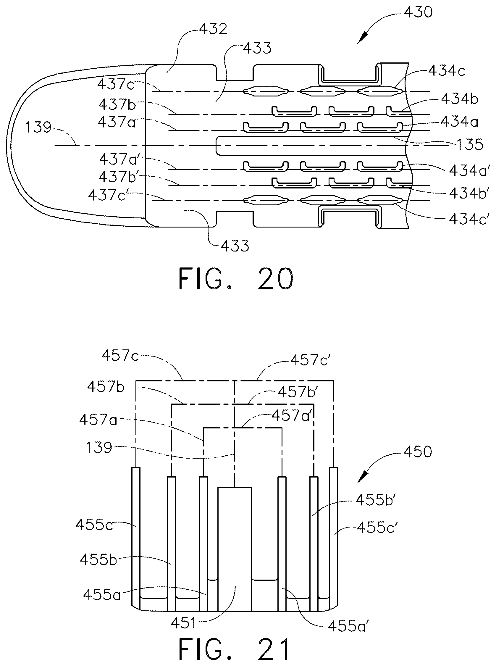
XML
uspto.report is an independent third-party trademark research tool that is not affiliated, endorsed, or sponsored by the United States Patent and Trademark Office (USPTO) or any other governmental organization. The information provided by uspto.report is based on publicly available data at the time of writing and is intended for informational purposes only.
While we strive to provide accurate and up-to-date information, we do not guarantee the accuracy, completeness, reliability, or suitability of the information displayed on this site. The use of this site is at your own risk. Any reliance you place on such information is therefore strictly at your own risk.
All official trademark data, including owner information, should be verified by visiting the official USPTO website at www.uspto.gov. This site is not intended to replace professional legal advice and should not be used as a substitute for consulting with a legal professional who is knowledgeable about trademark law.