Heat Exchanger Assemblies and Methods
Glass, III; Samuel W. ; et al.
U.S. patent application number 16/895661 was filed with the patent office on 2020-12-10 for heat exchanger assemblies and methods. This patent application is currently assigned to BATTELLE MEMORIAL INSTITUTE. The applicant listed for this patent is BATTELLE MEMORIAL INSTITUTE. Invention is credited to Samuel W. Glass, III, Morris S. Good, Matthew S. Prowant.
| Application Number | 20200388410 16/895661 |
| Document ID | / |
| Family ID | 1000004932187 |
| Filed Date | 2020-12-10 |


View All Diagrams
| United States Patent Application | 20200388410 |
| Kind Code | A1 |
| Glass, III; Samuel W. ; et al. | December 10, 2020 |
Heat Exchanger Assemblies and Methods
Abstract
Heat exchanger assemblies are provided that can include: a heat exchanger housing; at least one primary conduit operably coupled to the heat exchanger housing and configured to convey a primary heat exchange fluid; at least one secondary conduit operably coupled to the heat exchanger housing and configured to convey a secondary heat exchange fluid; at least one thermal interface between the primary and secondary fluids; and at least one sensor operably engaged with the thermal interface. Heat exchanger assemblies including molten salt, liquid metal, or water/steam as part of the heat exchange fluids of the heat exchanger assembly are provided. The heat exchanger assemblies can include: at least one thermal interface between primary and secondary heat exchange fluids of the heat exchanger assembly; and a sensor operably engaged with the at least one interface. The sensor must be installed in conjunction with the heat exchanger fabrication process as an embedded sensor. Methods for determining the structural integrity of a thermal interface within a heat exchanger assembly using the sensor are provided. The methods can include, while at least one or both of the primary or secondary conduits contain heat exchange fluid, reading structural integrity information of the thermal interface between the heat exchange fluids using one or more sensors engaged with the thermal interface.
| Inventors: | Glass, III; Samuel W.; (Richland, WA) ; Good; Morris S.; (Pasco, WA) ; Prowant; Matthew S.; (Richland, WA) | ||||||||||
| Applicant: |
|
||||||||||
|---|---|---|---|---|---|---|---|---|---|---|---|
| Assignee: | BATTELLE MEMORIAL INSTITUTE Richland WA |
||||||||||
| Family ID: | 1000004932187 | ||||||||||
| Appl. No.: | 16/895661 | ||||||||||
| Filed: | June 8, 2020 |
Related U.S. Patent Documents
| Application Number | Filing Date | Patent Number | ||
|---|---|---|---|---|
| 62858527 | Jun 7, 2019 | |||
| Current U.S. Class: | 1/1 |
| Current CPC Class: | G21C 15/28 20130101; G21C 1/22 20130101; G21C 3/24 20130101; G21C 17/022 20130101; F28F 27/00 20130101 |
| International Class: | G21C 17/022 20060101 G21C017/022; F28F 27/00 20060101 F28F027/00; G21C 3/24 20060101 G21C003/24; G21C 1/22 20060101 G21C001/22; G21C 15/28 20060101 G21C015/28 |
Goverment Interests
STATEMENT AS TO RIGHTS TO DISCLOSURES MADE UNDER FEDERALLY-SPONSORED RESEARCH AND DEVELOPMENT
[0002] This disclosure was made with Government support under Contract DE-AC0576RL01830 awarded by the U.S. Department of Energy. The Government has certain rights in the invention.
Claims
1. A heat exchanger assembly comprising: a heat exchanger housing; at least one primary conduit operably coupled to the heat exchanger housing and configured to convey a primary heat exchange fluid; at least one secondary conduit operably coupled to the heat exchanger housing and configured to convey a secondary heat exchange fluid; at least one thermal interface between the primary and secondary fluids; and at least one sensor operably engaged with the thermal interface.
2. The heat exchanger assembly of claim 1 wherein the sensor is integrated into the at least one thermal interface.
3. The heat exchanger assembly of claim 1 wherein the sensor is engaged with a secondary fluid exposed surface of the thermal interface.
4. The heat exchanger assembly of claim 1 further comprising a sensor housing defining a space about the sensor.
5. The heat exchanger assembly of claim 4 further comprising a sensor conduit extending through the heat exchanger housing to the space within the sensor housing.
6. The heat exchanger assembly of claim 4 further comprising processing circuitry operably coupled to the sensor.
7. The heat exchanger assembly of claim 6 wherein the processing circuitry is operably coupled to the sensor via one or more wires extending to the sensor within the sensor housing.
8. The heat exchanger assembly of claim 6 further comprising a sensor conduit extending through the heat exchanger housing to the space within the sensor housing, the one or more wires extending through the sensor conduit to the sensor.
9. The heat exchanger assembly of claim 1 wherein the at least one primary conduit is operably coupled to a primary conduit access plenum.
10. A heat exchanger assembly including molten salt, liquid metal, or water/steam as part of the heat exchange fluids of the heat exchanger assembly, the assembly comprising: at least one thermal interface between primary and secondary heat exchange fluids of the heat exchanger assembly; and a sensor operably engaged with the at least one thermal interface.
11. The heat exchanger assembly of claim 10 wherein one or both of the primary and/or secondary heat exchange fluids is one or both of lead, sodium or other low-melt metal.
12. The heat exchanger assembly of claim 10 wherein one or both of the primary and/or secondary heat exchange fluids is a molten salt.
13. The heat exchanger assembly of claim 10 wherein one or both of the primary and/or secondary heat exchange fluids is water or steam.
14. The heat exchanger assembly of claim 10 further comprising a fission reactor operably coupled to the heat exchanger assembly.
15. The heat exchanger assembly of claim 14 wherein the fission reactor utilizes a fuel molten salt.
16. The heat exchanger assembly of claim 15 wherein the heat exchanger assembly utilizes a coolant molten salt.
17. A method for determining the structural integrity of a thermal interface within a heat exchanger assembly, the method comprising while at least one or both of the primary and secondary conduits contain heat exchange fluid, reading structural integrity information of the thermal interface between the heat exchange fluids using one or more sensors engaged with the thermal interface.
18. The method of claim 17 further comprising providing multiple sensors associated with multiple locations within the heat exchanger assembly, and reading the structural integrity information from the one or more of the multiple locations.
19. The method of claim 17 further comprising reading the structural integrity information while heat is being exchanged between heat exchange fluids of the heat exchanger assembly.
Description
CROSS REFERENCE TO RELATED APPLICATION
[0001] This application claims priority to and the benefit of U.S. Provisional Patent Application Ser. No. 62/858,527 filed Jun. 7, 2019, entitled "Online Heat Exchanger Tube Guided Wave Sensor", the entirety of which is incorporated by reference herein.
TECHNICAL FIELD
[0003] The present disclosure related to heat exchanger assemblies and methods. In particular configurations, the present disclosure provides heat exchanger assemblies and methods for use with fission reactors such as light water pressurized reactors (PWRs), molten salt reactors (MSRs) and liquid metal reactors (LMRs).
BACKGROUND
[0004] Typical heat exchanger assemblies have at least two heat transfer fluids. These fluids are sometimes referred to as primary and secondary fluids of the heat exchanger assembly. Primary heat exchange fluids can enter the heat exchange assembly at a higher temperature than when the fluid exits the heat exchange assembly, and secondary heat exchange fluids can enter the heat exchange assembly at a lower temperature than when the fluid exits the heat exchange assembly. The heat exchange fluids can be provided within representative primary and secondary conduits.
[0005] Between these fluids is a thermal interface. This interface can be a wall or plate, multiple walls, or the wall can be part of a cylinder such as tubing or a conduit, for example. Regrettably, during operation of the assembly, the heat transfer fluids themselves, the heat transfer process, or a combination of the heat and fluid interaction, can lead to the breakdown of the integrity of these interfaces which can lead to the breakdown of the system or assembly of which the heat exchanger assembly is a component. In order to ensure the system operates consistently and reliably, the heat exchanger assembly, and particularly, the thermal interface can be inspected after one or both of the heat transfer fluids are removed from the assembly. Understandably, this requires shutting the system down for inspection, which can be costly or impractical. The present disclosure provides heat exchanger assemblies and methods that can be used to determine thermal interface integrity without removing either or both of the heat transfer fluids.
[0006] Additional advantages and novel features of the present disclosure will be set forth as follows and will be readily apparent from the descriptions and demonstrations set forth herein. Accordingly, the following descriptions of the present disclosure should be seen as illustrative of the disclosure and not as limiting in any way.
SUMMARY
[0007] Heat exchanger assemblies are provided that can include: a heat exchanger housing; at least one primary conduit operably coupled to the heat exchanger housing and configured to convey a primary heat exchange fluid; at least one secondary conduit operably coupled to the heat exchanger housing and configured to convey a secondary heat exchange fluid; at least one thermal interface between the primary and secondary fluids; and at least one sensor operably engaged with the thermal interface.
[0008] Heat exchanger assemblies including molten salt, liquid metal, or water/steam as part of the heat exchange fluids of the heat exchanger assembly are provided. The heat exchanger assemblies can include: at least one thermal interface between primary and secondary heat exchange fluids of the heat exchanger assembly; and a sensor operably engaged with at least one interface.
[0009] Methods for determining the structural integrity of a thermal interface within a heat exchanger assembly are provided. The methods can include, while at least one or both of the primary or secondary conduits contain heat exchange fluid, sensing structural integrity information of the thermal interface between the heat exchange fluids using one or more sensors engaged with the thermal interface.
[0010] In accordance with additional embodiments, heat exchanger assemblies are provided that can include: a heat exchanger housing; a hot leg conduit operably coupled to the heat exchanger housing, the hot leg plenum, and the hot leg entrance to the thermal interface volume; a cold leg conduit operably coupled to the heat exchanger housing, the cold leg plenum, and the cold leg exit from the thermal interface volume; at least one thermal interface between the hot and cold leg conduits; and a sensor operably engaged with the interface. The secondary fluid on the other side of the thermal interface also has an inlet and outlet. For heating heat exchangers, the secondary fluid enters cooler than the exit temperature. For cooling heat exchangers or condensers, the secondary fluid enters hotter than it exits. Heat exchangers can operate either as heating or cooling components and can function with the primary fluid flowing through the inside of a tubular thermal interface or on the outside of the tubular thermal interface but always with the secondary fluid on the opposite side of the thermal interface. The assemblies and/or methods of the present disclosure can be utilized with heating or cooling heat exchangers, but particular embodiments of the disclosure can be configured as a heating heat exchanger with primary fluid proceeding through the inside of a tubular thermal interface.
[0011] Heat exchanger assemblies including liquid metal, molten salt, water, or water/steam fluid as part of the primary or secondary fluid of the heat exchanger assembly are provided. The assemblies can include: at least one thermal interface between the primary and secondary fluids of the heat exchanger assembly; and a sensor is operably engaged with the thermal interface.
[0012] Methods for determining the structural integrity of a thermal interface within a heat exchanger assembly are also provided. The methods include; a sensor attached to the thermal interface--either near the hot or cold leg access plenum on the outside diameter (OD) of a tubular thermal interface; a heat exchanger housing; and a conduit and wire assembly to connect a signal from the sensor to an external multiplexer and measurement instrument.
DRAWINGS
[0013] Embodiments of the disclosure are described below with reference to the following accompanying drawings.
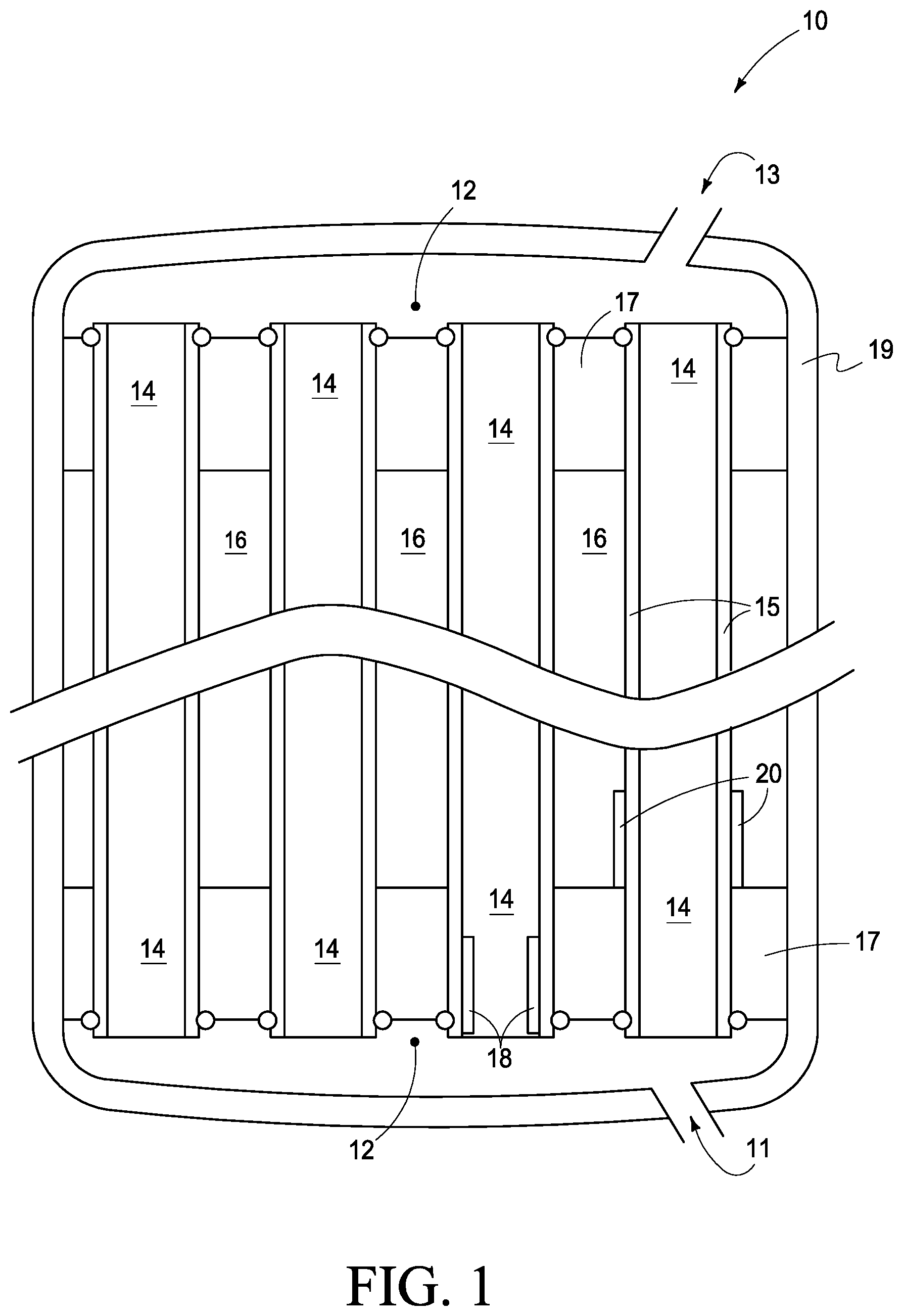
[0014] FIG. 1 is a heat exchanger assembly according to an embodiment of the disclosure.
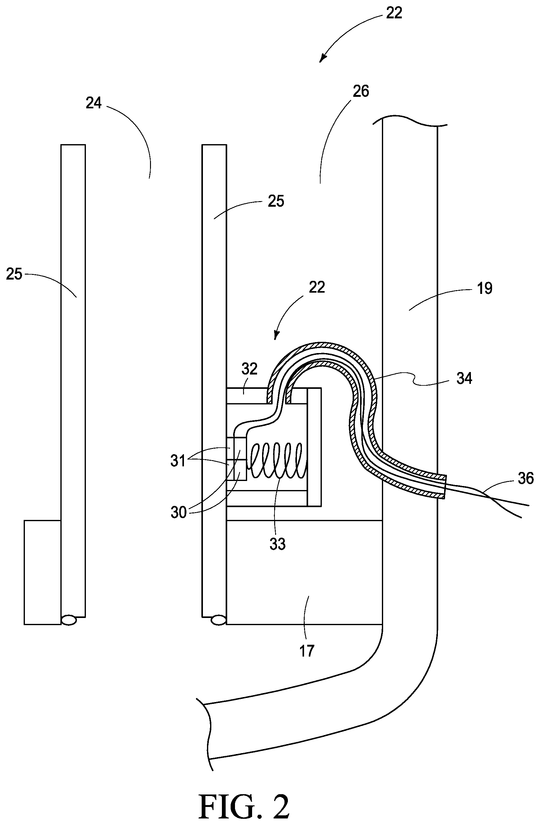
[0015] FIG. 2 is a portion of a heat exchanger assembly according to an embodiment of the disclosure.
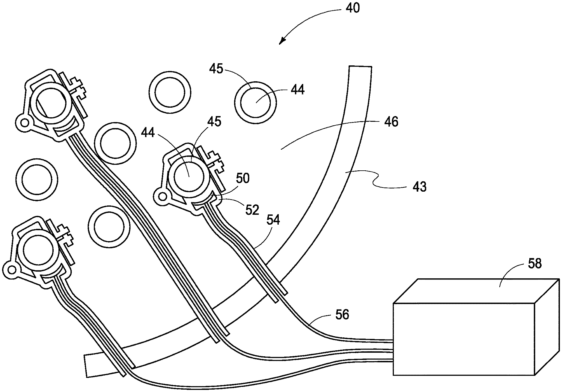
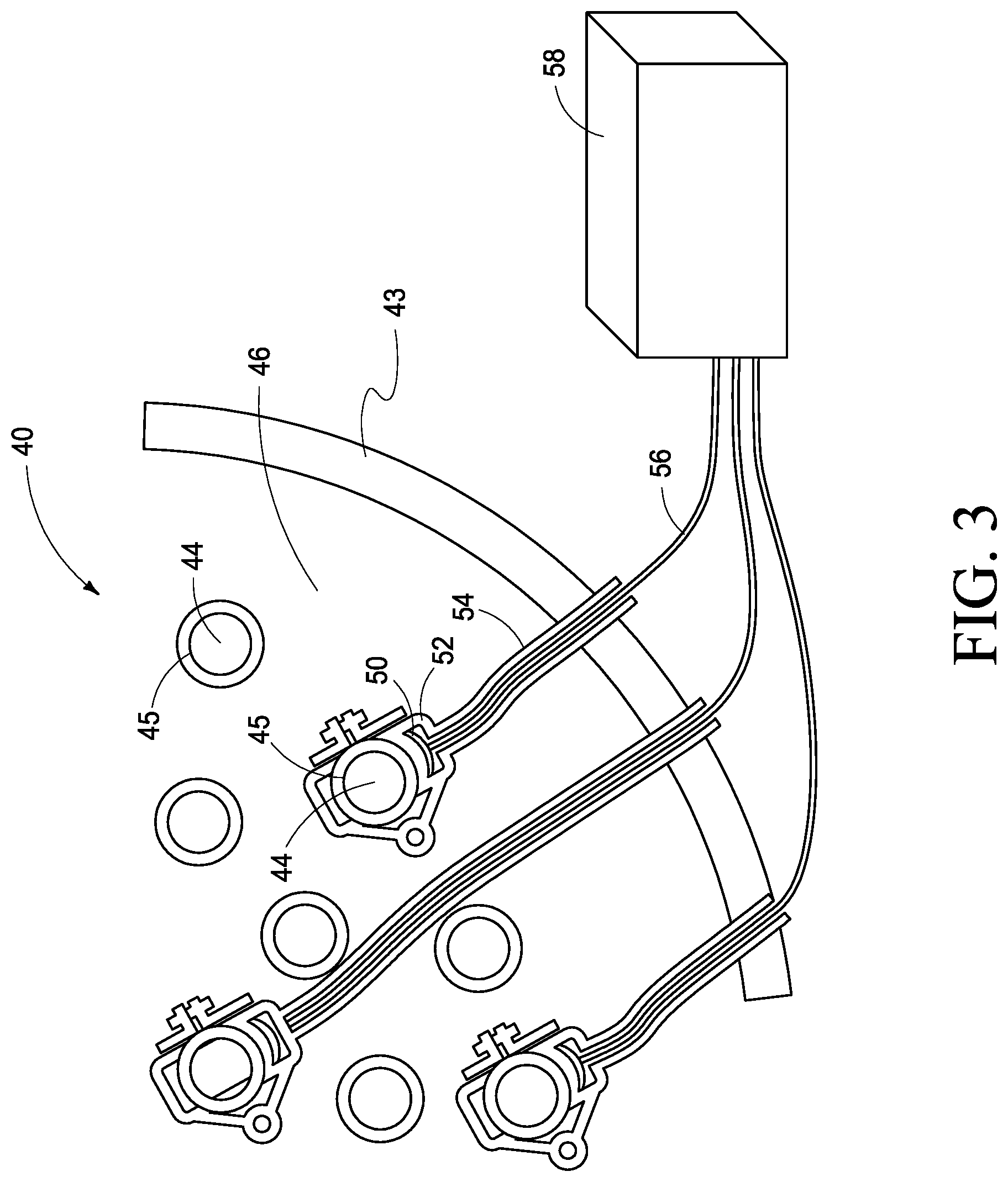
[0016] FIG. 3 is a heat exchanger assembly according to an embodiment of the disclosure.
[0017] FIG. 4 is processing circuitry utilized in accordance with the present disclosure.
[0018] FIGS. 5A-5B are depictions of sensor wave modes of interest.
[0019] FIG. 6 is a depiction of a portion of a heat exchanger assembly according to an embodiment of the disclosure.
[0020] FIG. 7 is example data acquired utilizing the assemblies and/or methods of the present disclosure.
[0021] FIGS. 8A-8B depict sensor configurations along a portion of a heat exchanger assembly and data acquired using those sensor configurations according to an embodiment of the disclosure.
[0022] FIGS. 9A-9B depict a heat exchanger assembly configured for use in a fission reactor according to an embodiment of the disclosure.
[0023] FIG. 10 is a depiction of an example fission reactor utilizing heat exchanger assemblies and methods of the present disclosure.
DESCRIPTION
[0024] This disclosure is submitted in furtherance of the constitutional purposes of the U.S. Patent Laws "to promote the progress of science and useful arts" (Article 1, Section 8).
[0025] The present disclosure will be described with reference to FIGS. 1-10. Referring first to FIG. 1, an example heat exchanger assembly 10 is shown that includes a pair of access plenums 12 operatively configured as hot (11) and cold (13) leg access plenums, 11 and 13 having primary conduits extending therebetween configured to convey primary transfer fluids 14. The access plenums can be connected by thermal exchange interfaces 15 and be operably associated with secondary heat exchange fluid 16 which can proceed via a secondary conduit defined by secondary tube sheet 17. In accordance with example implementations, the heat exchanger 10 can include sensors 18 and/or sensors 20.
[0026] Assembly 10 can be considered a shell and tube heat exchanger assembly having a cylindrical shell 19 with a 2 to 20 cm thick flat tube-sheet 17 on either end of the cylinder. Plenums 12 can be formed at the ends of the cylinder by the hemispherical shell-ends. These ends can be half-sphere caps containing one or more nozzles that allow fluid to be introduced or extracted from the end plenums and designated as the inlet or outlet plenums with inlet or outlet nozzle depending on whether fluid is entering or exiting the heat exchanger. Plenums 12 can be joined by hundreds to thousands of tubes (having thermal interfaces 15 and typically 1 to 3 cm diameter with 1 to 2 mm wall thickness) that are seal-welded to the tube-sheets 17.
[0027] Plenums 12 and the tube inside volumes can be connected as a single volume that can be filled with hotter primary fluid. The shell volume between the two tube sheets and on the outside of the tubes may be filled with cooler secondary fluid. This allows heat to flow across the tube wall without the two fluids mixing. Heat exchanger assemblies can also be provided with a single divided domed cylinder where the tubes are formed in an upside-down U-shape extending from the inlet quarter-sphere plenum to the outlet quarter-sphere plenum. This configuration can be designated as a U-Bend heat exchanger.
[0028] The heat transfer fluids for which the assemblies and/or methods of the present disclosure are applicable are those that typically do not allow for simple removal and inspection of the thermal interfaces. In particular light water nuclear fission reactor heat exchangers, the hot leg temperatures are nominally 320.degree. C.-370.degree. C. with cold leg temperatures .about.50.degree. C. less. For molten salt and other advanced reactors, hot leg temperatures can be >350.degree. C. and more typically >500.degree. C. with cold leg temperatures .about.50.degree. C. less. In most advanced reactor implementations, interrupting operation and removal of one or both of the fluids can be impossible and/or impractical.
[0029] Referring next to FIG. 2, a heat exchanger assembly 22 is shown in more detail. In accordance with an example implementation, heat exchanger assembly 22 includes sensor array 30 within sensor housing 32 operably coupled to the conduit shell penetration (sensor conduit) 34. Within the sensor conduit shell penetration 34 can be wiring 36 operably connected to the measurement instrument (not shown in this figure). In accordance with example configurations, primary fluid 24 can be operably associated with conduit 26 via thermal interface 25. Coupling between the sensor can be via an adhesive (up to .about.500.degree. C.), a brazing compound (for >500.degree. C.) 31, or via a pressure fit utilizing spring 33.
[0030] In accordance with another depiction of implementation and with reference to FIG. 3, the heat exchanger assembly 40 is shown having primary fluid conduits 44 with a thermal interface 45. The sensor 50 is operably engaged with the thermal interface 45. The sensor 50 is contained within a housing 52 providing a space in communication with shell penetration conduit 54 that can include a wire 56. This wire 56 can be operably coupled to processing circuitry 58, for example. Processing circuitry 58 can be multiplexing instrumentation.
[0031] In accordance with example implementations and with reference to FIGS. 1-3, clamp-on, adhesive, or braze-coupled high temperature piezoelectric sensors mounted near the union of the tube to the tube-sheet are envisioned to generate a Shear Horizontal guided ultrasonic wave that ideally will travel the full length of the tube or at least half way through the tube. If attenuation only allows the signal to travel half-way through the tube, a second sensor may be mounted to the other end of the tube to achieve full coverage of the heat interface. When such an ultrasonic wave reaches the opposite tube end, the signal is reflected back and may be sensed by the same signal generating piezoelectric sensor or a similar receiving piezoelectric sensor. When corrosion or crack anomalies occur in the tube, part of the signal will be reflected and will be detected by the receiving sensor at an earlier point in time than the reflected signal from the tube end. Anomalies originating from the tube ID or OD can be detected before they reach a 100% through-wall breach and ideally before exceeding 50% through wall. For very low temperature heat exchangers, high-piezoelectric coefficient piezoelectric sensor materials like Lead Zirconate Titanate (PZT-5a; Curie Temperature=350.degree. C.) may be used. Piezoelectric sensor materials like lithium niobate (LiNbO.sub.3), bismuth titanate (Bi.sub.4Ti.sub.3O.sub.12), aluminum nitride (AlN), and other materials have a lower piezoelectric coefficient but still perform up to and above 600-800.degree. C. Sensors mounted to the tube OD are subject to high temperatures but typically the lower temperature secondary fluid are on the tube ODs plus the flow forces are minimal in the stagnant area near the intersection of the tube and tube sheet.
[0032] The wires can be managed by a protective corrosion resistant structure and routed to and through the heat exchanger shell wall. This management can be characterized as an embedded sensor. Moreover, the sensor can be configured as an embedded sensor because it is installed as the heat exchanger is being fabricated. Spacing between the tubes may allow some periphery tubes to be instrumented after completing the tube/tube-sheet assembly but tubes away from the periphery can be inaccessible after all tubes are installed. Sensor signals can be brought through the tube bundle near the tube sheet or within the tube sheet to a commercial grade qualified cable penetration through the heat-exchanger shell to a multiplexing instrument located away from the heat using high temperature (ceramic or tungsten or other high-temperature insulation) cabling. Other high temperature electronics that may reduce or eliminate conducting penetrations through the shell are also contemplated.
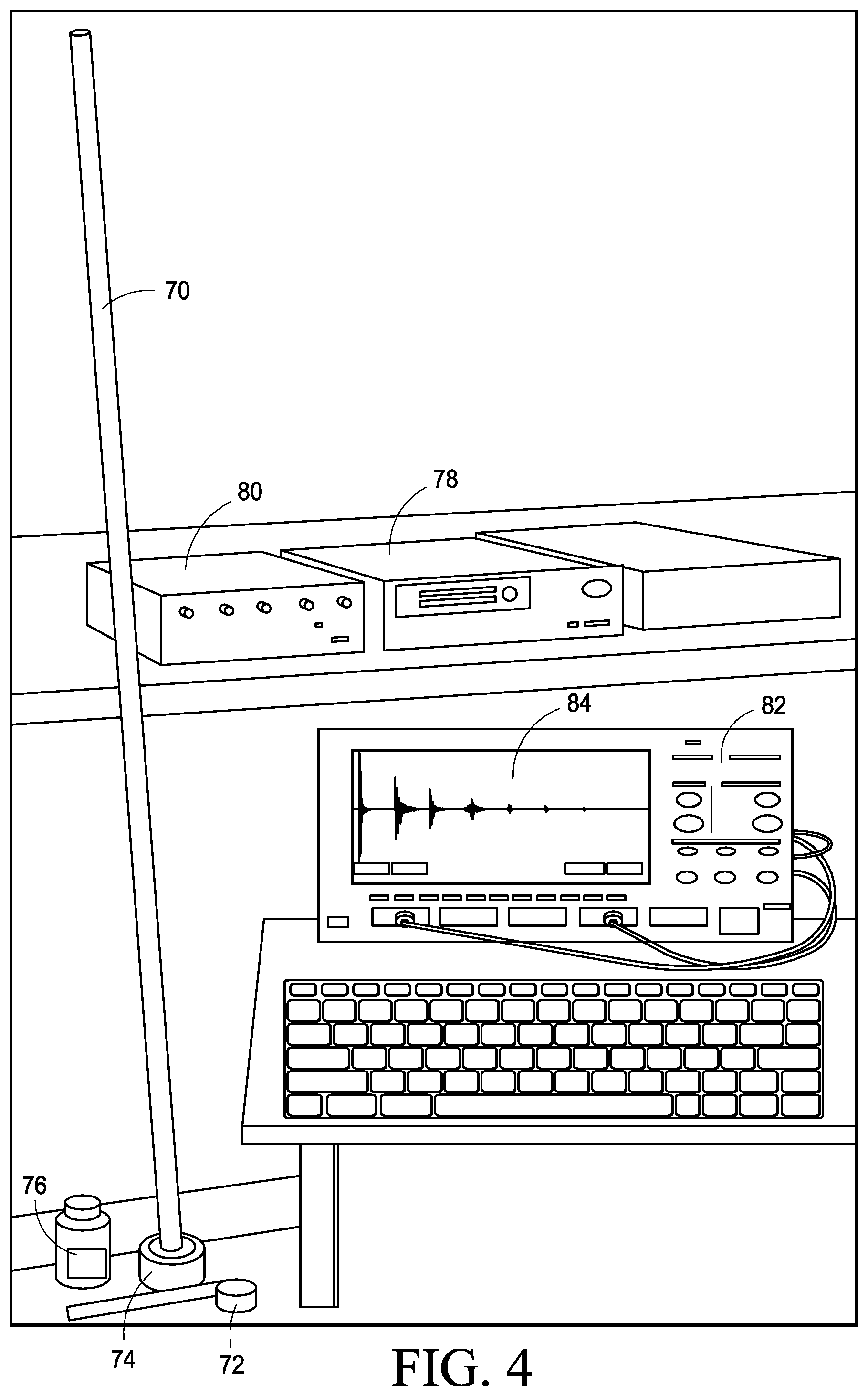
[0033] Referring next to FIG. 4, a laboratory configuration of the sensors coupled to the tube and the sensors coupled to the multiplexing equipment is shown. Some of the multiplexing equipment utilized as part of processing circuitry is shown. This multiplexing equipment and processing circuitry can provide readings for determining the integrity (presence or absence of cracks, pits, erosion, corrosion) of the thermal interfaces. Accordingly, the test configuration can include stainless steel, hasteloy, Inconel, or other corrosion-resistant metal tube 70, shear wave transducer 72, lamb wave transducer 74, couplant 76 (in the laboratory, honey; adhesive or brazing material for field installation), square wave for synchronization 78, ultrasonic pulse receiver 80, and digital oscilloscope 82 displaying responses 84.
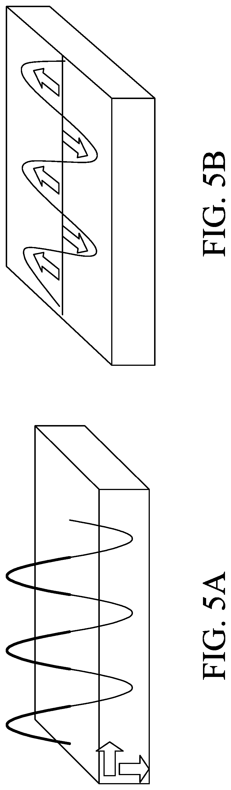
[0034] Referring to FIG. 5A-5B, wave modes are shown with 5A representing the L-0 wave and 5B representing the SH-0 Shear-Horizontal wave mode. In accordance with example implementations and with reference to FIG. 5A, the Lamb wave particle motion is perpendicular to the surface, and this motion can be attenuated by fluid. With reference to FIG. 5B, the Shear-Horizontal wave mode particle motion is parallel to the surface, and this motion is not substantially attenuated by surface-contacting fluid. These are some examples of wave modes that may be generated in plates and tubes associated with the heat exchangers. The piezoelectric crystals can be grown and cut differently to produce these different types of motions, and the sensors designed accordingly. In accordance with example implementations, the focus can be on the SH-0 wave mode to avoid influence from surface-contacting fluids.
[0035] For SH-0 to be nondispersive in steel, the frequency-thickness product (MHz-mm) may be less than approximately 1.5. Thus, for heat exchanger tubes with a wall thickness of nominally 0.8-1.5 mm, nondispersive frequencies can be <1-1.5 MHz. It has been recognized that higher frequencies can have better spatial resolution, but lower frequencies may be less attenuative.
[0036] SH mode transducers can be coupled by a material that can support shear stress. A thin layer of honey can work well for temporary (laboratory) sensors; however, an adhesive or a brazed metallurgical bond, or a high contact pressure between the sensor and the thermal interface is required for permanent (in situ) sensors. Sensor placement can be at tube ends or within the tube after the heat exchanger is fabricated however this region is typically a high flow area that can experience significant forces on both the sensor and wiring during operation, plus the sensor would occlude fluid flow through the tube thereby compromising the heat-exchange function of that tube. Thus, placing the sensor at the tube end or within the tube does not work for an on-line monitor. When sensors are incorporated during the heat exchange assembly fabrication process, however, the same kinds of SH-0 waves can be generated from a sensor mounted in the stagnant flow area of the tube outer diameter (OD) without compromising the heat-exchange tube function.
[0037] Referring next to FIG. 6, a portion of the heat exchanger assembly 200 is shown that includes primary fluid 202 and secondary fluid 204. In accordance with example implementations, sensor components 208 can be associated with the thermal transfer interface 206. In accordance with one example implementation, this can be a representation of the SH-0 mode piezoelectric sensor array adhered directly to the thermal transfer interface. The elemental direction can be important in order to reinforce the wave generated and as shown, the wave is generated in both directions equally.
[0038] In accordance with FIG. 6 sensor configuration, sensors 208 can include four elements side-to-side with alternating polarity, with three elements end-to-end circumferentially of the same polarity. This can propagate a forward wave 209 and a backward wave 211.
[0039] Several transducer (sensor) configurations were tested with the preferred configuration (3 circumferential elements.times.4 axial elements) shown in FIG. 6. This was the preferred configuration noting that acoustic noise was less when three elements were added length-to-length circumferentially to form a 90.degree. circumferential extent. Shear-wave coupling was found to be most effective at the point of contact. Signal strength is likely increased with more smaller circumferential elements. The frequency-thickness product for a 0.5 MHz wave and a 0.89 mm wall thickness was 0.5, which is well below the 1.5 criteria for a nondispersive wave.
[0040] Three anomalies representing flaws were placed in a 3.0 m (10 ft.) long 316 stainless steel tube as follows: Tube wall thickness--0.89 mm (0.035 in.); OD--191 mm (0.75 in.); 50% through-wall, 6.4 mm (0.25 in.) diameter flat-bottom hole emulating a pit; Through-wall, 6.4 mm (0.25 in.) diameter hole; 50% through-wall, 90-degree notch emulating a crack.
[0041] The sensor was composed primarily of PZT-5A (Curie temperature of 350.degree. C.) shear piezoelectric ceramic material. Each element had dimensions of 3.1 mm width, 1.79 mm thickness height, and 8.0 mm length. Chrome-gold electrodes were used with a chrome denoting the "+" polarity end. Honey was used as the ultrasonic shear-wave couplant between piezoelectric elements and the stainless-steel tube. A conventional digital oscilloscope and ultrasonic pulser-receiver were used to acquire data. A 4.times.3 array of low temperature (PZT-5a) sensors were installed as described above and demonstrated sensitivity to 50% crack/notch-like and pit-like machined flaws as well as through-wall hole flaws in a 10-ft tube at low temperature.
[0042] Referring to FIG. 7, in a configuration utilizing a 316 stainless steel seamless tube having a 3.0 m length and outside diameter of 19 mm and a wall thickness of 0.89 mm, a pit, through holes, and a notch was were provided. The pit was 6.4 mm in diameter, flat bottom, and 50% through wall depth. The Through hole was 6.4 mm in diameter, and the notch extended 90.degree. circumferentially and was 50% through wall depth. As shown in FIG. 7, all flaws were clearly detectable; the pit was noted at 230, the hole was noted at 232, the notch was noted at 234, and the tube end was noted at 236.
[0043] Referring next to FIGS. 8A and 8B, in order to investigate whether an array that covered only a small part of the interface would not be sensitive to flaws on the opposite side of the interface in a circumferential configuration such as a tube, arrays can be configured as shown in FIG. 8A and then plotted from a movable transducer rotated all the way around the tube, and data was taken at 2 cm, 5 cm, 10 cm, and 20 cm as shown in FIG. 8B. Referring to FIG. 8B, circumferential peak-to-peak (PTP) responses relative to max response @ 2 cm from 90-degree sensor at 2, 5, 10, and 20 cm axially from the transmitting sensor are demonstrated. The wave signal strength as shown is essentially uniform all the way around the circumferential configuration beyond 20 cm, which confirms that it is relatively unimportant to have a full circumference or two-sided transmitter, except perhaps to strengthen the overall transmitted signal.
[0044] Signals are not shown but it is noted that tests were performed with the same 3.times.4 sensor demonstrating that the SH-0 sensor signals were substantially unaffected by the presence or absence of water inside and outside the tube, and by the presence or absence of a simulated housing adhered to the tube.
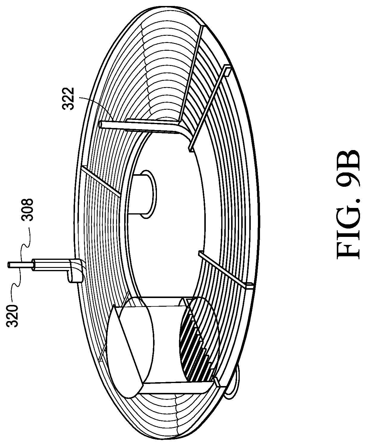
[0045] Referring next to FIGS. 9A and 9B, an example configuration of a heat exchanger assembly 300 is shown having secondary heat transfer fluid 302 within a conduit providing a thermal transfer interface 306 about a lead pool primary heat transfer fluid 304. In accordance with example implementations in this configuration, the primary lead pool fluid at 350-420.degree. C., for example and the secondary tube ID water/steam fluid is at 320-400.degree. C. System 300 can have housing and exit wire conduit 312 and through housing operably connected to thermal interface 306 can be detector assembly 308. In accordance with example implementations, an SH-0 wave can be traveling within thermal interface 306, and thermal interface 306 may have a crack or pit at 305. Accordingly, via sensor 308 and wires 312, processing circuitry 310 can record an initial signal 316, a near tube end signal 317, a flaw signal 318, and a far tube end signal 320.
[0046] In the field of Molten Salt Reactors (MSR), a variety of needs exist to sense and monitor conditions in harsh environments, and this plays a role in developing particular designs. All MSR designs have one or more heat exchangers. The broad experience with light water reactors (LWR) shows heat exchangers are among the most damage sensitive reactor system components, largely because the structural wall thickness that contain and isolate fluids are quite thin (1-2 mm). This short structural path is susceptible to corrosion and if corrosion occurs, it can quickly lead to a breach that will allow leakage and cross-contamination of primary or secondary fluid that will require shut-down and potentially very costly repair. The more limited experience with advanced reactors indicates the heat exchangers will be among the most at risk reactor system components for similar reasons.
[0047] These heat exchanger assemblies and methods can be utilized with various technologies, but for the most part, they can be particularly useful in the fission reactor technologies, particularly in molten or liquid metal heat transfer fluid technologies associated with fission reactors. These reactors are projected to provide extraordinarily inexpensive power per kilowatt hour, and can be relatively inexpensive to construct.
[0048] The principal advantages for molten salt and liquid metal reactors include that they are high temperature (vs. other fluid systems) and can configure as breeders/waste burners. They have low-pressure operation, stability of liquid under radiation, and high solubility of uranium and thorium (in fluoride salts, for example). The materials for these heat exchangers can be stainless steel, or Inconel, for example. Various layouts of these reactors can include the SFR (Super Phenix [France]), BN-600/800 [Russia], FFTR [US], Monju [Japan], EFR [China], PRISM [US], and TWR [US]. They can be used in the Hydromine lead reactors having a single-stage spiral heat-x, for example; the KAIROS power TRISO fuel-loaded molten salt reactor, for example; the FLIBE dissolved fuel molten salt reactor with hot gas heat-x and turbine, for example. These reactors can be operated at various conditions as shown in Table 1.
TABLE-US-00001 TABLE 1 Reactor Operating Parameter Comparison MSBR- Single Fluid MSFR AP1000 S-PRISM IMSR Inlet 566 675 280 363 625-660 temperature (.degree. C.) Outlet 705 775 322 510 670-700 temperature (.degree. C.) Primary coolant 11,820 18,920 14,300 2,992 5,400 flowrate (kg/s) Thermal power 2,250 3,000 3,400 1,000 400 (MW) Core power 22.2 330 110 120 9-14 density (MW/m.sup.3) Reactor ~0.1 ~0.1 15.5 ~0.1 ~0.1 pressure (MPa) (cover gas) (cover gas) (pressurizer) (cover gas) (cover gas) Core structure 63-87 0 ~50 ~63 70-95 volume (%)
[0049] Next, and with reference to FIG. 10, at least one example implementation of the heat exchangers provided in this disclosure is shown in the context of a fission reactor. The reactor can have highly radioactive heat transfer fluids. These heat transfer fluids can be molten salt fluids, lead or sodium liquid metal fluids, or water/steam but typically the reactor designs themselves require that the heat transfer fluid remain in place when operating and ideally during shutdowns, therefore making it difficult, or impossible, or very cost intensive, to completely drain the entire system, the heat exchanger assembly, and then visually or with eddy current inspect the heat exchanger by sending a probe through each of the heat exchanger thermal interface tubes. Therefore, the present disclosure provides a great advantage over the prior art, in that in situ monitoring of the integrity of the thermal interface of the heat exchangers can be accomplished. In accordance with one example fission reactor 200 including graphite moderators can include a fuel salt that may include materials such as uranium materials. Example materials can be LiF, BeF.sub.2, ThF.sub.4, UF.sub.4, and this primary coolant material can become heated during the fission process to a T1 at 204 and then pumped using a primary salt pump and motor assembly 206 to a heat exchanger assembly 10. Within this heat exchanger assembly, a coolant salt 224 can be provided, and the fuel salt can exit the heat exchanger at T2 which is substantially less than T1 at 208, for example. In accordance with example implementations, the T1 reactor exit and heat exchanger entrance piping or leg can be referred to as the hot leg of the heat exchanger. The T2 heat exchanger primary fluid exit is pumped to the reactor entrance and is referred to as the heat exchanger primary fluid exit or cold leg.
[0050] Referring next to another portion of this assembly and as shown in FIG. 10, a coolant salt 224 can be utilized to transfer thermal energy from the fuel salt. This coolant salt can exit the heat exchanger at a T3, and then provide thermal energy to steam generator 214. After leaving steam generator 214, coolant salt can be at a T4, which is substantially less than the T3 temperature exiting heat exchanger 10. This coolant salt can be provided via secondary salt pump 222 to return to heat exchanger 10 as a cold leg of heat exchanger 10. In accordance with example implementations and with reference to steam generator 214, the feedwater upon being exposed to the molten salt heat through the heat transfer interface to coolant salt 212 can have a T5 temperature, and that T5 temperature can elevate the water temperature to produce steam and allow for the operation of a turbo-generator 218. Upon leaving turbo-generator 218, temperature can be T6 at 220, and return (perhaps through a condenser) as recycled feedwater for more steam generation at steam generator 214.
[0051] In compliance with the statute, embodiments of the invention have been described in language more or less specific as to structural and methodical features. It is to be understood, however, that the entire invention is not limited to the specific features and/or embodiments shown and/or described, since the disclosed embodiments comprise forms of putting the invention into effect. The invention is, therefore, claimed in any of its forms or modifications within the proper scope of the appended claims appropriately interpreted in accordance with the doctrine of equivalents.
* * * * *
D00000
D00001
D00002
D00003
D00004
D00005
D00006
D00007
D00008
D00009
D00010
D00011
XML
uspto.report is an independent third-party trademark research tool that is not affiliated, endorsed, or sponsored by the United States Patent and Trademark Office (USPTO) or any other governmental organization. The information provided by uspto.report is based on publicly available data at the time of writing and is intended for informational purposes only.
While we strive to provide accurate and up-to-date information, we do not guarantee the accuracy, completeness, reliability, or suitability of the information displayed on this site. The use of this site is at your own risk. Any reliance you place on such information is therefore strictly at your own risk.
All official trademark data, including owner information, should be verified by visiting the official USPTO website at www.uspto.gov. This site is not intended to replace professional legal advice and should not be used as a substitute for consulting with a legal professional who is knowledgeable about trademark law.