Foldable Brace For Tieless One-sided Wall Forming
Korus; Pawel ; et al.
U.S. patent application number 16/856240 was filed with the patent office on 2020-12-10 for foldable brace for tieless one-sided wall forming. The applicant listed for this patent is Midwest Concrete & Masonry Supply, Inc.. Invention is credited to Pawel Korus, Charles Polesovsky.
| Application Number | 20200386004 16/856240 |
| Document ID | / |
| Family ID | 1000004837052 |
| Filed Date | 2020-12-10 |


| United States Patent Application | 20200386004 |
| Kind Code | A1 |
| Korus; Pawel ; et al. | December 10, 2020 |
FOLDABLE BRACE FOR TIELESS ONE-SIDED WALL FORMING
Abstract
A foldable brace assembly for supporting concrete formwork includes a ground brace member pivotably coupled with an end of a wall brace member, such that the wall brace member can pivot to be generally parallel or generally perpendicular relative to the ground brace. With the wall brace member perpendicular to the ground brace member in an erect position, a diagonal brace member detachably couples between an upper portion of the wall brace member and the other end of the ground brace member. The brace assembly may be locked in the erect position, such as by inserting a pin in aligned openings in the wall brace member and the ground brace member. When the brace assembly is not in use, the pin may be removed and the brace assembly can pivot to a folded position with the wall brace member can pivot to be generally parallel to the ground brace.
| Inventors: | Korus; Pawel; (Chicago, IL) ; Polesovsky; Charles; (Bel Air, MD) | ||||||||||
| Applicant: |
|
||||||||||
|---|---|---|---|---|---|---|---|---|---|---|---|
| Family ID: | 1000004837052 | ||||||||||
| Appl. No.: | 16/856240 | ||||||||||
| Filed: | April 23, 2020 |
Related U.S. Patent Documents
| Application Number | Filing Date | Patent Number | ||
|---|---|---|---|---|
| 62857313 | Jun 5, 2019 | |||
| Current U.S. Class: | 1/1 |
| Current CPC Class: | E04G 21/26 20130101; E04G 17/14 20130101; E04G 2011/067 20130101 |
| International Class: | E04G 17/14 20060101 E04G017/14; E04G 21/26 20060101 E04G021/26 |
Claims
1. A foldable brace assembly for supporting concrete formwork, the foldable brace assembly comprising: a ground brace member; a wall brace member pivotably coupled with a first end of the ground brace member, wherein the wall brace member is configured to pivot between a folded position and an erect position with the wall brace member perpendicular relative to the ground brace member; and a diagonal brace member detachably coupled between an upper portion of the wall brace member and a second end of the ground brace member when the wall brace member is in the erect position.
2. The foldable brace assembly of claim 1, wherein when in the folded position, the wall brace member is in parallel to relative to the ground brace member.
3. The foldable brace assembly of claim 1, wherein the wall brace member is fixedly attached to a corner bracket, and wherein the first end of the ground brace member is pivotally attached to the corner bracket with a bolt.
4. The foldable brace assembly of claim 3, wherein the corner bracket includes an upper opening and a lower opening, wherein a pin is configured to removably engage the upper opening and the ground brace member in the folded position, and wherein the pin is configured to removably engage the lower opening and the ground brace member in the erect position.
5. The foldable brace assembly of claim 3, wherein the corner bracket includes an angled support surface that is configured to support a tie bar that attaches to a tie down anchor embedded in a concrete foundation for holding the ground brace member against a ground surface.
6. The foldable brace assembly of claim 1, wherein the wall brace member includes a pair of beams spaced apart to form a channel that is configured to engage a formwork panel at a plurality of vertical locations along the vertical channel.
7. The foldable brace assembly of claim 6, further comprising a waler that includes a horizontal channel that is configured to engage the formwork panel at a plurality of locations along the horizontal channel, and wherein the wall brace member directly attaches to the waler.
8. The foldable brace assembly of claim 6, wherein the ground brace member includes a pair of beams spaced apart a distance equal to the beams of the wall brace member.
9. The foldable brace assembly of claim 8, wherein a corner bracket is fixedly attached between the pair beams at a lower end of the wall brace member, and wherein the corner bracket is pivotally attached between the pair beams at the first end of the ground brace member.
10. A foldable brace assembly for supporting concrete formwork, the foldable brace assembly comprising: a first brace assembly having a first ground member and a first wall member pivotably coupled together and pivotable between a folded position and an erect position; a first diagonal brace member detachably coupled between an upper portion of the first wall member and a rear end of the second ground member when the brace assembly is pivoted to an erect position with the first wall member perpendicular relative to the first ground member; a second brace assembly having a second ground member and a second wall member pivotably coupled together and pivotable between a folded position and an erect position; a second diagonal brace member detachably coupled between an upper portion of the second wall member and a rear end of the second ground member when the brace assembly is pivoted to an erect position with the second wall member perpendicular relative to the second ground member; and a set of cross braces that attach at and extend between the first and second brace assemblies in the erect positions.
11. The foldable brace assembly of claim 10, wherein, with the first and second diagonal brace members detached, the first and second brace assemblies are pivotable to the folded position with the first and second wall members in parallel alignment with the first and second ground members.
12. The foldable brace assembly of claim 10, wherein the first and second brace assembles each comprise a corner bracket that is fixedly coupled to lower ends of the first and second wall members and pivotally coupled to front ends of the first and second ground members.
13. The foldable brace assembly of claim 12, wherein the corner brackets each include an upper opening and a pin that is configured to removably engage the upper opening and the respective first or second ground member in the folded position, and wherein the corner brackets each include a lower opening and a pin that is configured to removably engage the lower opening and the respective first or second ground member in the erect position.
14. The foldable brace assembly of claim 12, wherein the corner brackets each includes an angled support surface that is configured to support a tie bar that attaches to a tie down anchor.
15. A foldable brace assembly for supporting concrete formwork, the foldable brace assembly comprising: a ground brace member that comprises two beams attached together along the length of the beams to secure the beams together; a wall brace member that comprises two beams attached together along the length of the beams to secure the beams together; a corner bracket attached at a lower end of the wall brace member between the beams of the wall brace member; and wherein a front end of the ground brace member is pivotably attached to the corner bracket, and wherein the wall brace member is configured to pivot between a folded position with the wall brace member parallel to the ground brace member and an erect position with the wall brace member perpendicular to the ground brace member.
16. The foldable brace assembly of claim 15, further comprising a diagonal brace member detachably coupled between an upper portion of the wall brace member and a rear end of the ground brace member when the wall brace member is in the erect position.
17. The foldable brace assembly of claim 15, wherein the two beams of the ground brace member each have a U-shaped cross-sectional shape oriented opposite each other.
18. The foldable brace assembly of claim 15, wherein the two beams of the wall brace member are consistently spaced from each other along a length of the wall brace member to form a channel, wherein a fastener engages one of a plurality of locations along the channel to attach the wall brace member a formwork panel.
19. The foldable brace assembly of claim 15, wherein the corner bracket includes an upper opening and a lower opening, wherein a pin is configured to removably engage the upper opening and the ground brace member in the folded position, and wherein the pin is configured to removably engage the lower opening and the ground brace member in the erect position.
20. The foldable brace assembly of claim 15, wherein the corner bracket includes an angled support surface that is configured to support a tie bar that attaches to a tie down anchor embedded in a concrete foundation for holding the ground brace member against a ground surface.
Description
CROSS-REFERENCE TO RELATED APPLICATION
[0001] This application claims priority under 35 U.S.C .sctn. 119(e) to U.S. Provisional Patent Application No. 62/857,313, filed Jun. 5, 2019, the disclosure of this prior application is considered part of this application and is hereby incorporated by reference in its entirety.
TECHNICAL FIELD
[0002] The present disclosure generally relates to a formwork support brace that is used to support wall panels and forms, such as during the construction of a concrete wall or other structure.
BACKGROUND
[0003] When forming concrete slab walls, it is common to temporarily brace formwork that is used to support a concrete wall while the concrete is poured into the formwork and cures. The temporary bracing may be arranged on the outer side of the formwork and may be anchored to the ground to support the pressure exerted by the concrete poured on the inner side of the formwork. Once the concrete has sufficiently cured to support itself, the bracing and formwork may be removed to expose the surface of the concrete wall.
SUMMARY
[0004] The present disclosure provides a foldable brace assembly that is used to support formwork, such as for forming a concrete wall or slab with a surface in an upright or vertical orientation. The foldable brace assembly includes at least one ground brace member and at least one wall brace member that fold together. For example, an end portion of the wall brace member can be pivotably coupled with an end portion of the ground brace member, such that the brace assembly can pivot between a folded position with the wall brace member in general parallel alignment with the ground brace member and an erect position with the wall brace member in general perpendicular orientation relative to the ground brace member. The brace assembly may be locked in the erect position, such as by inserting a pin in aligned openings in the end portions of the wall brace member and the ground brace member. When the brace assembly is not in use, the pin may be removed and the brace assembly can pivot to the folded position for easy storage and transportation.
[0005] With the wall brace member and the ground brace member generally perpendicular to each other in the erect position, a diagonal brace member attaches between an upper portion of the wall brace member and the other end portion of the ground brace member to place the brace assembly in an assembled configuration. In the assembled configuration, the brace assembly may be disposed against an outer side of a formwork panel, such as a 12 foot wall panel, and anchored to the ground, such as by attaching to anchors cast in concrete footings. The single brace assembly may then brace and support loads exerted by the formwork panel, such as the 12 foot wall panel, in an upright orientation. It is understood that two or more brace assemblies may be arranged at a spaced distance from each other along the supported formwork panel and attached together with tubular cross braces extending between adjacent wall brace members and between adjacent ground brace members. The number of brace assemblies, spacing between the brace assemblies, and dimensions of the brace members may vary and be adjusted to accommodate the height and configuration of the formwork and associated concrete structure.
[0006] According to one aspect of the present disclosure, a foldable brace assembly for supporting concrete formwork includes a ground brace member and a wall brace member. The lower end of the wall brace member is pivotably coupled with an end of the ground brace member, such that the brace assembly can pivot between a folded position with the wall brace member in general parallel alignment with the ground brace member and an erect position with the wall brace member in general perpendicular orientation relative to the ground brace member. With the wall brace member and the ground brace member in the erect position, a diagonal brace member detachably couples between an upper end of the wall brace member and the other end of the ground brace member. Optionally, a corner bracket may be pivotally disposed between the ends of the wall and ground brace members, such as with the lower end of the wall brace member connected to the corner bracket and the ground brace member pivotally coupled, such as via pin or bolt, a to the corner bracket. To facilitate locking the positions of the wall brace member, the corner bracket may include an upper opening and a lower opening, where a pin may be configured to engage the lower opening in the folded position and the upper opening in the erect position.
[0007] According to another aspect of the present disclosure, a foldable brace assembly may be adjustable to attach to various points on the supported formwork. For example, the wall brace member may include a vertical channel that is configured to engage a fastener at a plurality of locations along the vertical channel, where the fastener may extend from the wall brace member toward the supported formwork panel to engage a waler or the like. The waler may also include a horizontal channel that is configured to engage a fastener, such as a tieback, for attaching to the formwork panel at a plurality of locations along the horizontal channel.
[0008] To reduce the need for the large storage areas and high-load assembly cranes typically associated with traditional one-sided wall braces, the foldable brace assembly disclosed herein allows the ground and wall brace members to fold together for efficient storage and transportation, along with the possibility to manually assemble and position the brace assemblies on the formwork without a crane or other heavy and expensive lifting equipment. Also, once a project is complete, the foldable brace assemblies may be disassembled and later reassembled, such as in the same or a different configuration, to accommodate different projects or otherwise support different wall panel formwork.
[0009] These and other objects, advantages, purposes, and features of the present disclosure will become apparent upon review of the following specification in conjunction with the drawings.
BRIEF DESCRIPTION OF THE DRAWINGS
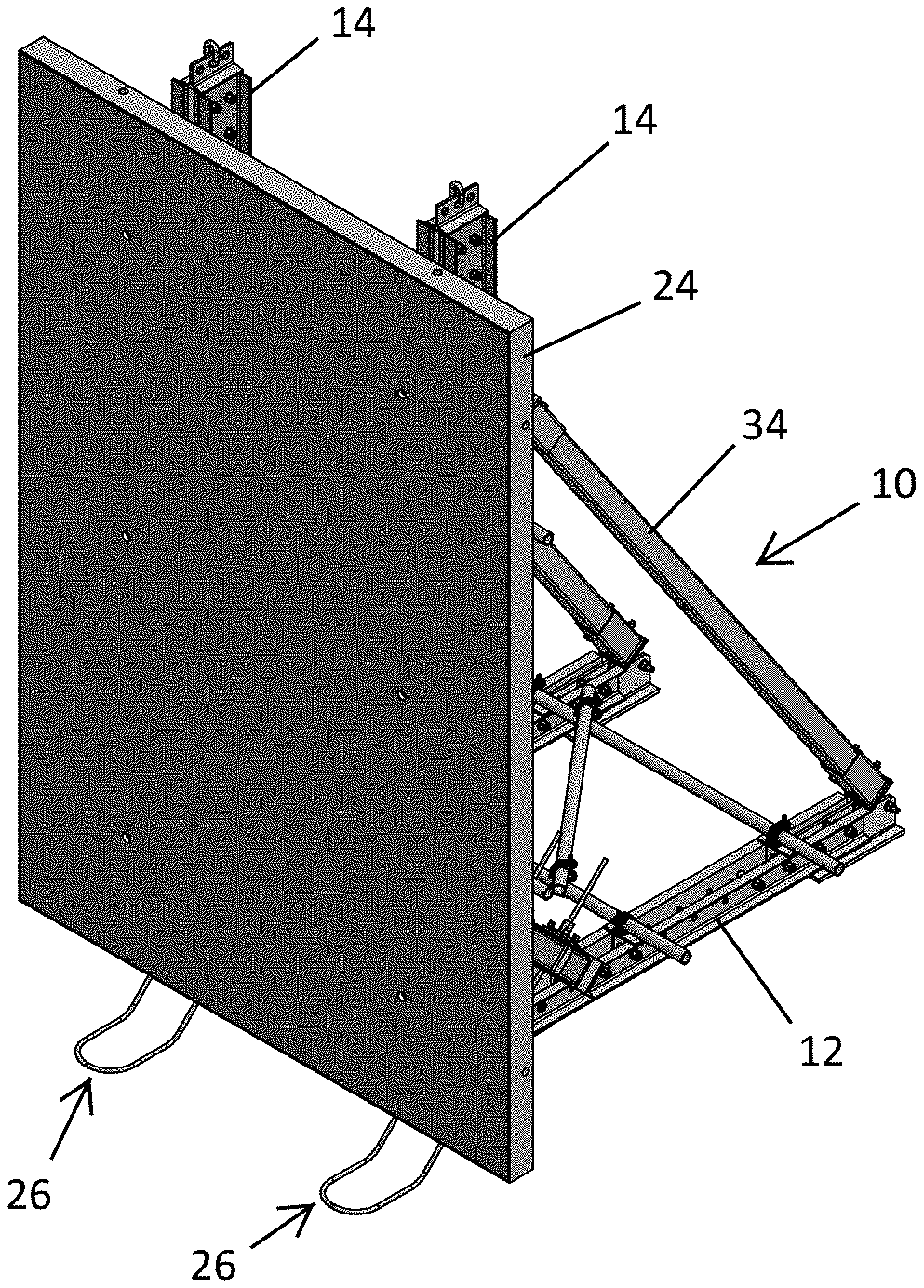
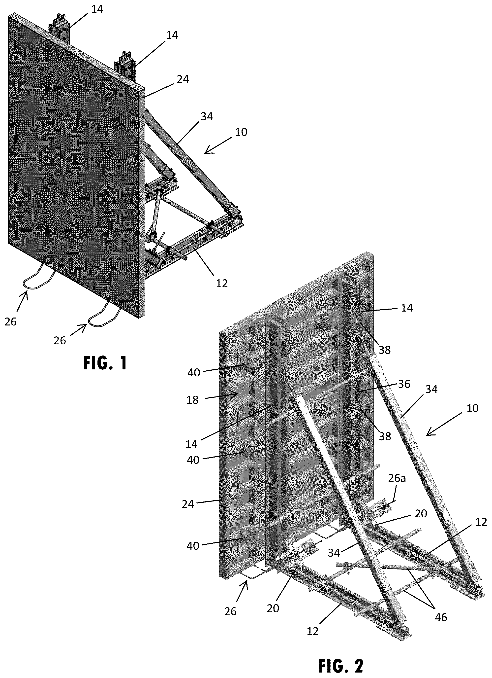
[0010] FIG. 1 is a front perspective view of a wall panel form supported by two foldable braces assemblies connected to tie down anchors;
[0011] FIG. 2 is a rear perspective view of the wall panel form and foldable braces assemblies shown in FIG. 1;
[0012] FIG. 2A is a rear perspective view of a vertical cross section of the wall panel form shown in FIG. 1;
[0013] FIG. 2B is a side elevation view of the section of the wall panel form and foldable braces assembly shown in FIG. 2A;
[0014] FIG. 3 is a front perspective view of the foldable braces assemblies shown in FIG. 1;
[0015] FIG. 4 is a rear perspective view of the foldable braces assemblies shown in FIG. 3;
[0016] FIG. 5 is a side elevation view of the foldable braces assemblies shown in FIG. 3;
[0017] FIG. 5A is an enlarged view of section A shown in FIG. 5, illustrating the tie down anchor engagement with foldable brace;
[0018] FIG. 6 is a top plan view of the foldable braces assemblies shown in FIG. 3;
[0019] FIG. 7 is a rear elevation view of the foldable braces assemblies shown in FIG. 3;
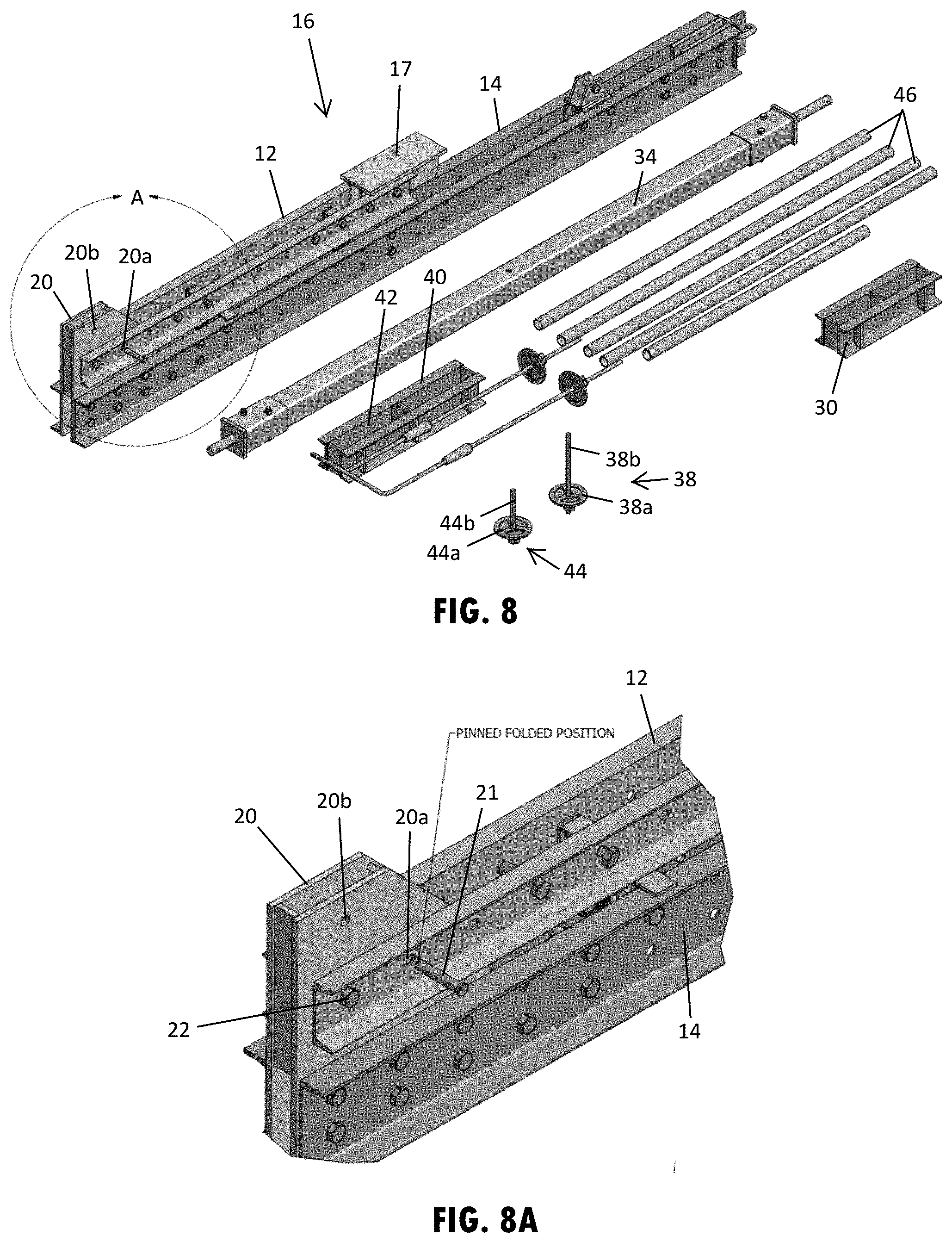
[0020] FIG. 8 is a perspective view the disassembled foldable brace assemblies shown in FIG. 3, illustrating the wall and ground brace members in a folded position;
[0021] FIG. 8A is an enlarged view of section A shown in FIG. 8, illustrating the corner bracket of the ground brace member and a pin position to engage the corner bracket; and
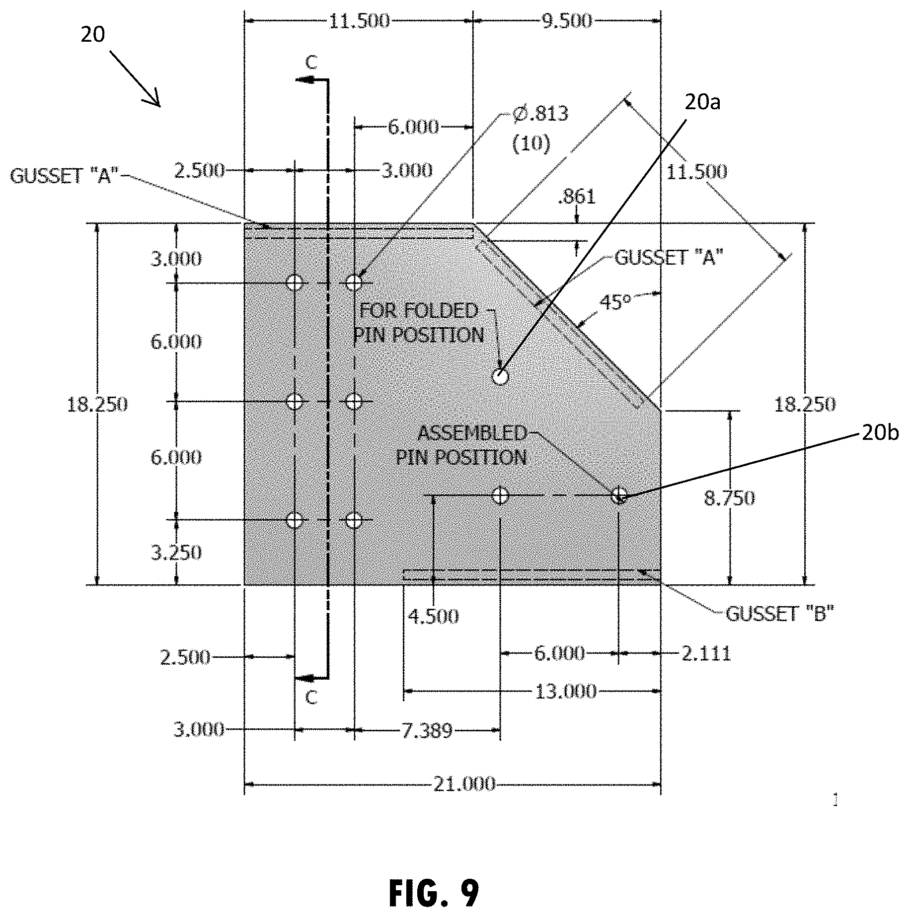
[0022] FIG. 9 is an elevation view of the corner bracket shown in FIG. 8A.
DETAILED DESCRIPTION
[0023] Referring now to the drawings and the illustrative embodiments depicted therein, a foldable brace assembly 10, such as shown in FIGS. 1-9, is capable of being stored and transported in a folded configuration and then unfolded and assembled at a worksite to support concrete formwork, such as for forming a concrete wall or slab in an upright or vertical orientation. The foldable brace assembly 10 includes at least one ground brace member 12 and at least one wall brace member 14 that are pivotably attached together. As shown for example in FIGS. 3 and 8, an end portion of the wall brace member 14 is pivotably coupled with an end portion of the ground brace member 12, such that the brace assembly 10 can pivot between a folded position 16 (FIG. 8) with the wall brace member 14 overlapping and in general parallel alignment with the ground brace member 12 and an erect position 18 (FIGS. 1-7) with the wall brace member 14 in general perpendicular orientation relative to the ground brace member 12.
[0024] As shown in FIGS. 1-5, the ground brace member 12 includes a two metal beams 13a, 13b that are attached together with nuts and bolts at multiple locations along the length of the beams to secure the beams together in parallel alignment with each other. The beams 13a, 13b each have a U-shaped cross-sectional shape oriented opposite each other, arranging the central portion of the U-shape nearest the central portion of the opposing beam. As shown in FIGS. 3 and 4, the beams 13a, 13b are consistently spaced from each other along the length of the ground brace member 12. To maintain the spacing, as shown in FIGS. 4 and 8, the rear ends of the beams 13a, 13b have a foot bracket 17 sandwiched and bolted between the beams and a corner bracket 20 is sandwiched between the front ends of the beams 13a, 13b. It is also contemplated that additional spacers at different locations along the length of the ground brace member may be used to maintain the spacing and additional attachment, such as welding, may be used to secure the beams relative to each other.
[0025] Similar to the ground brace member 12, as shown in FIGS. 1-5, the wall brace member 14 includes a two metal beams 15a, 15b that are attached together with two rows nuts and bolts at multiple locations along the length of the beams to secure the beams together in parallel alignment with each other. The beams 15a, 15b each have a U-shaped cross-sectional shape oriented opposite each other, arranging the central portion of the U-shape nearest the central portion of the opposing beam, such as to together form an I-shape. As shown in FIGS. 3 and 4, the beams 15a, 15b are consistently spaced from each other to provide a channel 36 along the length of the wall brace member 14. To maintain the spacing that forms the channel 36, as shown in FIG. 4, a lifting plate is sandwiched between the top ends of the beams 15a, 15b and the corner bracket 20 is sandwiched between the bottom ends of the beams 15a, 15b. As a result, the spacing between the beams 15a, 15b of the wall brace member 14 is substantially equal to the spacing between along the beams 13a, 13b of the ground brace member 12. It is also contemplated that additional spacers at different locations along the length of the wall brace member may be used to maintain the spacing.
[0026] The pivotal engagement of the end portions of the brace members 12, 14 may be reinforced with bracketry to maintain a stable connection when unfolded for assembly to support formwork. For example, the lower end of the wall brace member 14 may incorporate or otherwise be fixed to a corner bracket 20, such as shown in FIGS. 5 and 5A. The ground brace member 12 may then be pivotally coupled with a fastener, such as via a pin or bolt 22 (FIGS. 5A and 8A), to the corner bracket 20 at the lower end portion of the wall brace member 14. The lower end of the wall brace member 14 shown in FIG. 5A is fixedly coupled to the corner bracket 20, such as with a weld and/or the illustrated bolted connection. It is contemplated that the pivotal coupling of the ground brace member and wall brace member in additional embodiments may be constructed directly between the brace members or with additional or alternative intermediate components or brackets or the like to provide foldability to the brace assembly. As another example, a corner bracket may be fixed to the ground brace member and the wall brace member may be pivotally attached to the corner bracket.
[0027] As further shown in FIGS. 5A and 8A, the brace assembly 10 may be locked or engaged in the folded position 16 during storage and transport and may also be locked or engaged in the erect position 18 during assembly to more easily allow for positioning at or near the formwork in the desired orientation. As shown in FIGS. 8-9, the corner bracket 20 includes an upper opening 20a and a lower opening 20b, where a pin 21 may extend into and engage the upper opening 20a to hold or lock the brace assembly in the folded position 16 or extend into and engage the lower opening 20b to hold or lock the brace assembly 10 in the erect position 18. The pin 21 may prevent movement of the brace members relative to each other by also extending into and engaging an opening in the ground brace member 12. However, it is contemplated that in additional embodiments that the pin may engage an edge surface of the ground brace member, such as to act as a stop to rotation or pivoting of the ground brace member relative to the wall brace member, and similarly lock the positions of the brace assembly.
[0028] As shown in FIGS. 1 and 2, the brace assembly 10 is unfolded in the assembled configuration and disposed against an outer side of a formwork panel 24 and temporarily anchored to the ground. It is understood that prior to anchoring the wall and ground brace members to the ground, they may be leveled on a ground surface, such as with adjustable jacks or the like. To provide the anchoring, the lower portion of the brace assembly 10 may be temporarily attached to an anchor that is cast or embedded in the ground, such as a tie down anchor 26 that is cast in a concrete footing 28 as shown in FIG. 2B. The tie down anchor 26 may be a loop-shaped anchor that provides two stems 26a that protrude upward at an angle away from the ground surface, whereby the brace assembly 10 is disposed between the two stems 26a of the tie down anchor 26. The brace assembly 10 is shown in FIGS. 2-2B engaged to the tie down anchor 26 by a tie bar 30 that is secured down against an upper angled surface of the corner bracket 20 of the anchor assembly 10 by wing nuts 32 that each threadably engage down the stems 26a of the tie down anchor 26. To provide threaded engagement of the wing nuts 32 with the tie down anchor 26, the stems 26a may include threaded anchor rods that attach to a lower loop portion 26b of the tie down anchor 26, such as with the use of intermediate couplers 26c as shown in FIG. 2B. It is also contemplated that the tie down anchor in additional examples may be a single threaded anchor or may be differently configured with separate anchors, such as individual tie rods or the like on opposing sides of a single brace assembly.
[0029] With the brace assembly 10 in the erect position 18, a diagonal brace member 34 detachably couples between an upper portion of the wall brace member 14 and the rear end portion of the ground brace member 12. The diagonal brace member 34 is shown in FIGS. 1-8 having a tubular beam with a square cross-sectional shape that extends consistently along a length of the beam. As shown in FIGS. 3 and 4, the end couplings 35 of the diagonal brace member 34 include a sleeve 35a that is inserted over and fastened to an end of the tubular beam. A threaded post 35b extends through the sleeve 35a and is threadably attached to an end plate that is welded over an open end of the sleeve 35a. The ends of the threaded post 35b may be detachably connected to the respective ground and wall brace member 12, 14 with the use of brackets that are attached in the channels of the ground and wall brace members 12, 14 with threaded bolts or other fasteners that are capable of being manually disconnected, such as with or without the use of hand tools or the like. The threaded posts 35b of the diagonal brace members 34 may have an adjustable length that are adjusted by rotating the threaded post 35b relative to the sleeve 35a to the provide a length that accommodates a firm brace connection of the diagonal brace member 34.
[0030] The diagonal brace member 34 and associated couplings are configured to withstand compressive and shear forces, respectively, that are exerted by the formwork panel 24 when under the load of the concrete used to form the wall or structure on the inner side of the formwork. As shown in FIG. 5, the wall brace member 14 has a height of approximately 144 inches or 12 feet, such that the brace assembly 10 is configured to support a formwork panel 24 that is 12 feet or taller. It is understood that two or more brace assemblies may be arranged at a spaced distance from each other along the supported formwork panel and attached together with tubular cross braces 46, such as shown in FIGS. 1 and 2, extending between adjacent wall brace members 14 and between adjacent ground brace members 12. The cross braces may be attached with camps or other fasteners. The number of brace assemblies, spacing between the brace assemblies, and dimensions of the brace members may vary and be adjusted to accommodate the formwork and associated concrete structure.
[0031] The foldable brace assembly 10 may also be adjustable to attach to various points on the supported formwork 24. As shown in FIG. 2A, the wall brace member 14 may include a vertical channel 36 that is configured to engage a fastener 38, such as a tie bolt or tieback fastener, at a plurality of locations along the vertical channel 36. The fastener 38 may extend from the wall brace member 14 toward the supported formwork panel 24 to engage a horizontal beam, such as a waler 40 as shown in FIG. 2A. The waler 40 may also include a horizontal channel 42 that is configured to engage a fastener 44, such as a tie bolt or tieback fastener, for attaching to the formwork panel 24 at a plurality of locations along the horizontal channel 42. As shown in FIG. 8, the fasteners 38, 44 may include wing nuts 38a, 44a that threadably engage a threaded rod portion 38b, 44b of the fastener 38, 44 to secure the fastener in place in the respective channels. Thus, when loosening or removing one or more of the fasteners 38, 44, the waler 40 may be repositioned to a desired location on the formwork panel 24 for engagement, such that the brace assembly 10 is configurable to support the formwork panel at a desired position and thus also configurable to support various sizes and types of formwork panels.
[0032] To reduce the need for the large storage areas and high-load assembly cranes typically associated with traditional one-sided wall braces, the foldable brace assembly disclosed herein allows the ground and wall brace members to fold together for efficient storage and transportation, along with the possibility to manually assemble and position the brace assemblies on the formwork without a crane or other heavy and expensive lifting equipment. As understood, the brace assembly may be considered "tieless" due to its lack of any anchoring ties on the internal reinforcements of the formed concrete structure. Also, once a project is complete, the foldable brace assemblies may be disassembled and later reassembled, such as in the same or a different configuration, to accommodate different projects or otherwise support different wall panel formwork. The foldable brace assembly disclosed herein may be used with multiple and various types of construction projects and applications. The cross-sectional geometry, material type selections, and material thickness within the cross-sectional profile of the components of the brace assembly may be configured for such a particular use and the desired loading and performance characteristics as generally understood.
[0033] For purposes of this disclosure, the term "coupled" (in all of its forms, couple, coupling, coupled, etc.) generally means the joining of two components directly or indirectly to one another. Such joining may be stationary in nature or movable in nature; may be achieved with the two components and any additional intermediate members being integrally formed as a single unitary body with one another or with the two components; and may be permanent in nature or may be removable or releasable in nature, unless otherwise stated.
[0034] Also for purposes of this disclosure, the terms "upper," "lower," "right," "left," "rear," "front," "vertical," "horizontal," "inner," "outer," "inner-facing," "outer-facing," and derivatives thereof shall relate to the invention as oriented in FIG. 1. However, it is to be understood that the invention may assume various alternative orientations, except where expressly specified to the contrary. It is also to be understood that the specific devices and processes illustrated in the attached drawings, and described in this specification are simply exemplary embodiments of the inventive concepts defined in the appended claims. Hence, specific dimensions and other physical characteristics relating to the embodiments disclosed herein are not to be considered as limiting, unless the claims expressly state otherwise.
[0035] Changes and modifications in the specifically described embodiments may be carried out without departing from the principles of the present invention, which is intended to be limited only by the scope of the appended claims as interpreted according to the principles of patent law. The disclosure has been described in an illustrative manner, and it is to be understood that the terminology which has been used is intended to be in the nature of words of description rather than of limitation. Many modifications and variations of the present disclosure are possible in light of the above teachings, and the disclosure may be practiced otherwise than as specifically described.
* * * * *
D00000
D00001
D00002
D00003
D00004
D00005
D00006
D00007
XML
uspto.report is an independent third-party trademark research tool that is not affiliated, endorsed, or sponsored by the United States Patent and Trademark Office (USPTO) or any other governmental organization. The information provided by uspto.report is based on publicly available data at the time of writing and is intended for informational purposes only.
While we strive to provide accurate and up-to-date information, we do not guarantee the accuracy, completeness, reliability, or suitability of the information displayed on this site. The use of this site is at your own risk. Any reliance you place on such information is therefore strictly at your own risk.
All official trademark data, including owner information, should be verified by visiting the official USPTO website at www.uspto.gov. This site is not intended to replace professional legal advice and should not be used as a substitute for consulting with a legal professional who is knowledgeable about trademark law.