Spreader For Particulate Material With Improved Spread Control
GRAY; Geof J. ; et al.
U.S. patent application number 16/770140 was filed with the patent office on 2020-12-10 for spreader for particulate material with improved spread control. This patent application is currently assigned to Salford Group Inc.. The applicant listed for this patent is Salford Group Inc.. Invention is credited to John Mark AVERINK, Bradley William BAKER, Jesse Abram DYCK, Joshua Scott FIELDS, Geof J. GRAY, Steven Ray OWENBY.
| Application Number | 20200384496 16/770140 |
| Document ID | / |
| Family ID | 1000005049068 |
| Filed Date | 2020-12-10 |


View All Diagrams
| United States Patent Application | 20200384496 |
| Kind Code | A1 |
| GRAY; Geof J. ; et al. | December 10, 2020 |
SPREADER FOR PARTICULATE MATERIAL WITH IMPROVED SPREAD CONTROL
Abstract
An apparatus for spreading particulate material has a bin for holding particulate material, a rotatable disc for broadcasting the particulate material to a ground surface, a conveyor for conveying the particulate material in a particulate material path from the hopper to the rotatable disc, and a plurality of sluices situated in the particulate material path between the bin and the rotatable disc. Each sluice receives a portion of the particulate material and delivers the portion of particulate material to a radial and/or angular position on the rotatable disc. At least one of the sluices is independently moveable to adjust the radial and/or angular position on the rotatable disc to which the portion of particulate material from the at least one independently moveable sluice is delivered.
| Inventors: | GRAY; Geof J.; (Burford, CA) ; AVERINK; John Mark; (Norwich, CA) ; BAKER; Bradley William; (Stratford, CA) ; DYCK; Jesse Abram; (London, CA) ; FIELDS; Joshua Scott; (Clermont, GA) ; OWENBY; Steven Ray; (Blairsville, GA) | ||||||||||
| Applicant: |
|
||||||||||
|---|---|---|---|---|---|---|---|---|---|---|---|
| Assignee: | Salford Group Inc. Salford ON |
||||||||||
| Family ID: | 1000005049068 | ||||||||||
| Appl. No.: | 16/770140 | ||||||||||
| Filed: | December 6, 2018 | ||||||||||
| PCT Filed: | December 6, 2018 | ||||||||||
| PCT NO: | PCT/CA2018/051562 | ||||||||||
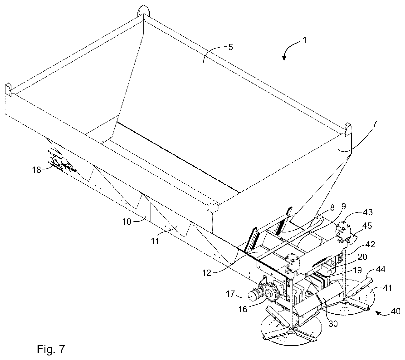
| 371 Date: | June 5, 2020 |
Related U.S. Patent Documents
| Application Number | Filing Date | Patent Number | ||
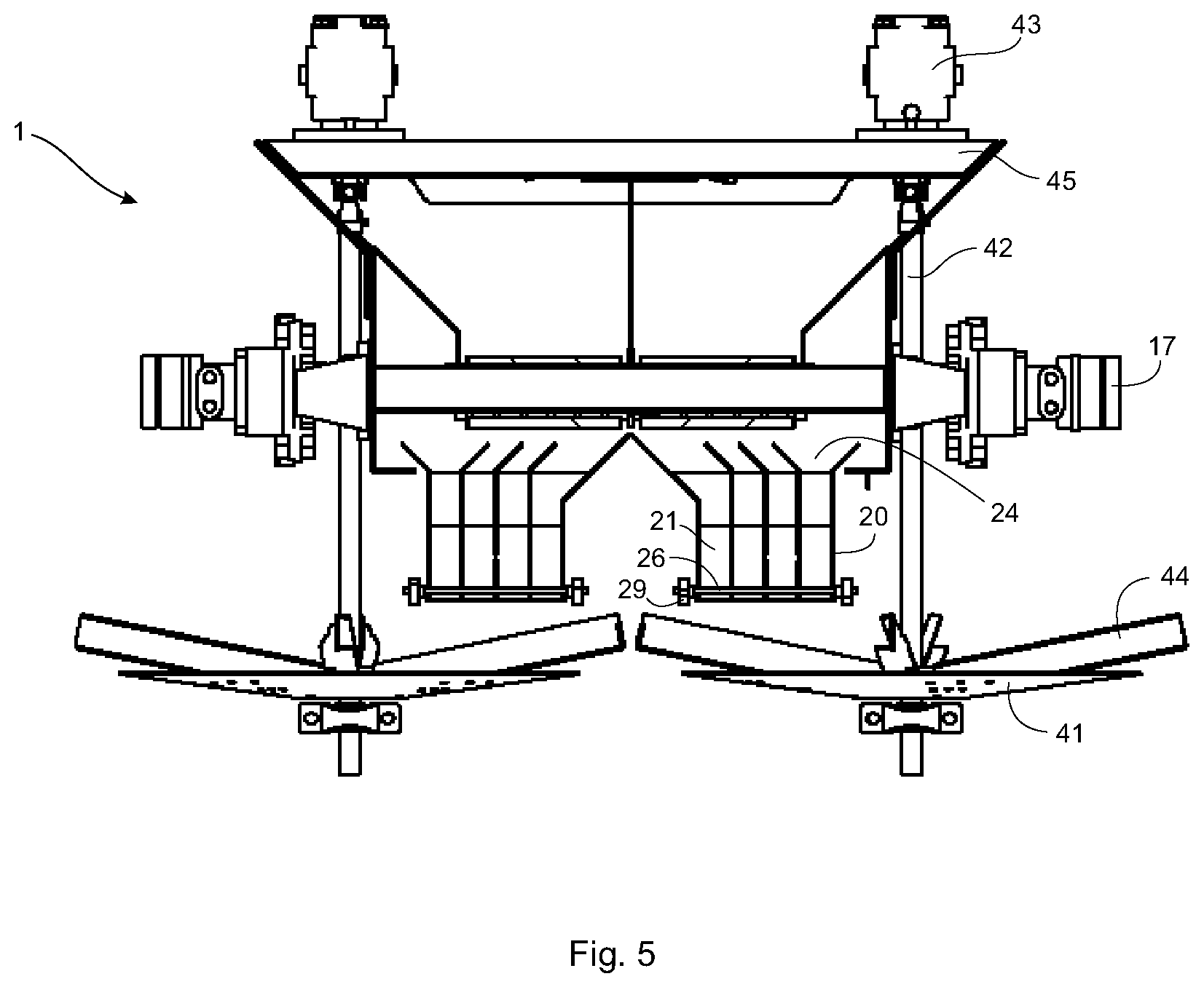
|---|---|---|---|---|
| 62595844 | Dec 7, 2017 | |||
| Current U.S. Class: | 1/1 |
| Current CPC Class: | E01C 2019/2075 20130101; B05C 19/008 20130101; B05C 19/06 20130101; A01C 15/122 20130101; B05D 1/28 20130101; A01C 15/006 20130101; A01C 19/02 20130101; E01C 19/203 20130101 |
| International Class: | B05C 19/00 20060101 B05C019/00; B05C 19/06 20060101 B05C019/06; B05D 1/28 20060101 B05D001/28 |
Claims
1. An apparatus for spreading particulate material, the apparatus comprising: a bin for holding particulate material; a rotatable disc for broadcasting the particulate material to a ground surface; a conveyor for conveying the particulate material in a particulate material path from the hopper to the rotatable disc; and, a plurality of sluices situated in the particulate material path between the bin and the rotatable disc, each sluice receiving a portion of the particulate material and delivering the portion of particulate material to a radial and/or angular position on the rotatable disc, at least one of the sluices independently moveable to adjust the radial and/or angular position on the rotatable disc to which the portion of particulate material from the at least one independently moveable sluice is delivered, each sluice comprising substantially vertically oriented side walls, an open first end for receiving the particulate material from the conveyor, an inclined floor inclined downwardly from the first end to an open second end of the sluice so that the particulate material in the sluice flows freely out the open second end.
2. The apparatus of claim 1, wherein each of the plurality of sluices is independently moveable to adjust the radial positions on the rotatable disc to which the portions of particulate material from the independently moveable sluices are delivered.
3. The apparatus of claim 1, wherein the rotatable disc comprises first and second rotatable discs, and the plurality of sluices comprises first and second sets of sluices, the first set of sluices delivering the particulate material to the first rotatable disc and the second set of sluices delivering the particulate material to the second rotatable disc.
4. The apparatus of claim 1, wherein the plurality of sluices comprises at least four sluices.
5. The apparatus of claim 1, wherein the open first end is at a top of the sluice.
6. The apparatus of claim 1, wherein the sluices are independently moveable to adjust at least the radial position on the rotatable disc to which the portion of particulate material is delivered.
7. The apparatus of claim 1, further comprising one or more crank adjusters, one or more linear actuators, one or more hydraulic cylinders, one or more pneumatic cylinders, or some combination thereof for moving the sluices.
8. The apparatus of claim 1, wherein: the sluices are disposed transversely to one another to form a series of parallel channels; each of the sluices is independently moveable to adjust the radial positions on the rotatable disc to which the portions of particulate material from the independently moveable sluices are delivered; the substantially vertically oriented side walls of each sluice comprise elongated slots; and, the plurality of sluices comprises an elongated securing element that passes through the aligned elongated slots in the side walls so that each of the sluices rests on the elongated securing element, each of the sluices independently translatable on the elongated securing element when not secured by the securing element and not translatable when secured by the securing element.
9. The apparatus of claim 8, wherein the elongated securing element comprises a threaded rod and one or more nuts, wherein tightening the one or more nuts on the rod immobilizes the sluices and loosening the one or more nuts on the rod permits the sluices to translate on the rod.
10. The apparatus of claim 1, wherein the substantially vertically oriented side walls of each sluice are not common with any of the other sluices.
11. A method of controlling spread pattern of a particulate material broadcasted by a spinner spreader, the method comprising: permitting particulate material to flow through a plurality of sluices situated in a particulate material path between a bin and a rotatable disc of a spinner spreader, each sluice receiving a portion of the particulate material and delivering the portion of particulate material to a radial and/or angular position on the rotatable disc, each sluice comprising substantially vertically oriented side walls, an open first end for receiving the particulate material from the conveyor, an inclined floor inclined downwardly from the first end to an open second end of the sluice so that the particulate material in the sluice flows freely out the open second end; and, adjusting the radial and/or angular position on the rotatable disc to which the portion of particulate material from at least one of sluices is delivered by moving the at least one of the sluices relative to the rotating disc thereby changing the spread pattern of the particulate material broadcasted by the rotatable disc.
12. The method according to claim 11, wherein each of the sluices in the plurality of sluices is independently moveable.
13. The method according to claim 11 or 12, wherein rate at which the particulate material is delivered to the rotatable disc is controlled to further change the spread pattern of the particulate material.
14. The method according to claim 11, wherein rotational speed of the rotatable disc is controlled to further change the spread pattern of the particulate material.
Description
CROSS-REFERENCE TO RELATED APPLICATIONS
[0001] This application claims the benefit of U.S. Provisional Patent Application U.S. Ser. No. 62/595,844 filed Dec. 7, 2017, the entire contents of which is herein incorporated by reference.
FIELD
[0002] This application relates to apparatuses for spreading particulate material.
BACKGROUND
[0003] Spinner spreaders are known in the art for broadcasting particulate material to a ground surface (e.g. an agricultural field, a road, and the like) for a variety of applications, for example, spreading fertilizer, fertilizer supplements, seed, sand, gravel, road salt, lime and the like. Spread pattern of the particulate material is dependent on spinner design, including size, placement and orientation of fins on a spinner disc, and on rotational speed of the disc. Distance to which particulate material is ejected may be controlled by the spinner design and the rotational speed of the disc, but uniformity of the spread pattern may be unduly affected when the disc speed is changed, especially when the rotational speed is reduced below a certain rate. However, for some applications, it is desirable to be able to reduce the disc speed while maintaining a uniform spread pattern. In other applications, it is desirable to be able to manipulate the spread pattern to provide a desired pattern.
[0004] Therefore, there remains a need in the art for a spinner spreader that provides greater control over spread pattern.
SUMMARY
[0005] There is provided an apparatus for spreading particulate material, the apparatus comprising: a bin for holding particulate material; a rotatable disc for broadcasting the particulate material to a ground surface; a conveyor for conveying the particulate material in a particulate material path from the hopper to the rotatable disc; and, a plurality of sluices situated in the particulate material path between the bin and the rotatable disc, each sluice receiving a portion of the particulate material and delivering the portion of particulate material to a radial and/or angular position on the rotatable disc, at least one of the sluices independently moveable to adjust the radial and/or angular position on the rotatable disc to which the portion of particulate material from the at least one independently moveable sluice is delivered, each sluice comprising substantially vertically oriented side walls, an open first end for receiving the particulate material from the conveyor, an inclined floor inclined downwardly from the first end to an open second end of the sluice so that the particulate material in the sluice flows freely out the open second end.
[0006] A method of controlling spread pattern of a particulate material broadcasted by a spinner spreader, the method comprising: permitting particulate material to flow through a plurality of sluices situated in a particulate material path between a bin and a rotatable disc of a spinner spreader, each sluice receiving a portion of the particulate material and delivering the portion of particulate material to a radial and/or angular position on the rotatable disc, each sluice comprising substantially vertically oriented side walls, an open first end for receiving the particulate material from the conveyor, an inclined floor inclined downwardly from the first end to an open second end of the sluice so that the particulate material in the sluice flows freely out the open second end; and, adjusting the radial and/or angular position on the rotatable disc to which the portion of particulate material from at least one of sluices is delivered by moving the at least one of the sluices relative to the rotating disc thereby changing the spread pattern of the particulate material broadcasted by the rotatable disc.
[0007] In an embodiment, each of the plurality of sluices is independently moveable to adjust the radial and/or angular positions on the rotatable disc to which the portions of particulate material from the independently moveable sluices are delivered. In an embodiment, the plurality of sluices comprises at least four sluices. Each of the sluices may be moveable longitudinally, transversely, vertically, rotationally or any combination thereof. Each sluice may be independently moveable in at least one of a longitudinal, transverse, vertical or rotational direction. Each sluice may be independently moveable in two, three or all four of the longitudinal, transverse, vertical and rotational directions. In some embodiments, the sluices may be collectively moveable in at least one of the longitudinal, transverse, vertical and rotational directions. The sluices may be collectively moveable in two, three or all four of the longitudinal, transverse, vertical and rotational directions. The ability to move the sluices in a number of different directions permits fine tuning of the spread pattern of the particulate material.
[0008] In an embodiment, each sluice comprises substantially vertically oriented side walls, an open top for receiving the particulate material from the conveyor, an inclined floor inclined downwardly from a first end to an open second end of the sluice so that the particulate material in the sluice flows freely out the open second end. In an embodiment, the sluices are disposed transversely to one another to form a series of parallel channels. In one embodiment, adjacent sluices of the series of parallel channels abut each other at the substantially vertically oriented side walls. In one embodiment, the sluices do not share common side walls.
[0009] The sluices are moveable using any suitable mechanism. For example, the sluices may be moveable manually, using one or more crank adjusters, using one or more linear actuators, using one or more hydraulic cylinders, using one or more pneumatic cylinders, or some combination thereof. Each sluice may be moveable by its own dedicated mechanism or mechanisms, or may be moveable by a mechanism or mechanisms common to more than one sluice. In an embodiment, the plurality of sluices comprises an elongated securing element that passes through aligned elongated slots in the side walls so that each of the sluices rests on the elongated securing element, each of the sluices independently translatable on the elongated securing element when not secured by the securing element and not translatable when secured by the securing element. In an embodiment, the elongated securing element comprises a threaded rod and one or more nuts, wherein tightening the one or more nuts on the rod immobilizes the sluices and loosening the one or more nuts on the rod permits the sluices to translate on the rod.
[0010] In an embodiment, the rotatable disc comprises first and second rotatable discs, and the plurality of sluices comprises first and second sets of sluices, the first set of sluices delivering the particulate material to the first rotatable disc and the second set of sluices delivering the particulate material to the second rotatable disc.
[0011] Deliberate control of the radial and/or angular position to which the particulate material is delivered to the rotatable disc and the speed at which the particulate material is delivered to the rotatable disc may be used to develop custom spread patterns for the particulate material. The rotational speed of the rotatable disc controls rotational positions at which the particulate material is broadcasted from the rotatable disc. The speed at which the particulate material is delivered to the rotatable disc controls the amount of particulate material delivered from the rotatable discs in a given time period. Manipulating these variables permits fine tuning the spread pattern of particulate material. Additionally, accuracy of the spread pattern may be further adjusted by altering the size and/or shape of the open rear ends of the sluices. For example, narrower sluices may reduce the likelihood of the particulate material shattering when delivered to the rotatable disc by localizing the particulate material more toward the center of the disc where rotational speed of the disc is lower.
[0012] Further features will be described or will become apparent in the course of the following detailed description. It should be understood that each feature described herein may be utilized in any combination with any one or more of the other described features, and that each feature does not necessarily rely on the presence of another feature except where evident to one of skill in the art.
BRIEF DESCRIPTION OF THE DRAWINGS
[0013] For clearer understanding, preferred embodiments will now be described in detail by way of example, with reference to the accompanying drawings, in which:
[0014] FIG. 1 depicts a rear perspective view of one embodiment of a spinner spreader;
[0015] FIG. 2 depicts a side view of the spinner spreader of FIG. 1;
[0016] FIG. 3 depicts a rear view of a spinner spreader of FIG. 1;
[0017] FIG. 4 depicts a cross-sectional view through A-A in FIG. 2;
[0018] FIG. 5 depicts a cross-sectional view through B-B in FIG. 2;
[0019] FIG. 6 depicts a cross-sectional view through C-C in FIG. 3;
[0020] FIG. 7 depicts the spinner spreader of FIG. 1 including deflection plates over spinner discs;
[0021] FIG. 8 depicts a magnified side view of a rear end of the spinner spreader of FIG. 7;
[0022] FIG. 9 depicts a division of particulate material spread pattern produced by the spinner spreader of FIG. 7 with all sluices at the same longitudinal position;
[0023] FIG. 10A, FIG. 10B and FIG. 10C illustrate how particle spread pattern is affected by increasing (FIG. 10B) and decreasing (FIG. 10C) rotational speed of the spinner discs of the spinner spreader of FIG. 7;
[0024] FIG. 11A, FIG. 11B and FIG. 11C illustrate how particle spread pattern is affected by forwardly (FIG. 11B) and rearwardly (FIG. 11C) moving a sluice of the spinner spreader of FIG. 7; and,
[0025] FIG. 12 illustrates how moving sluices and adjusting rotational speed of spinner discs can be used to manipulate particle spread pattern to switch off one of eight broadcast sections of the spinner spreader of FIG. 7.
DETAILED DESCRIPTION
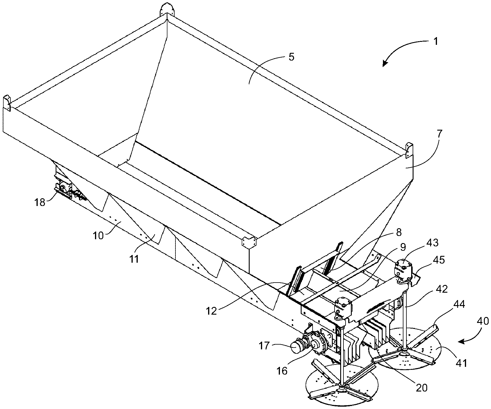
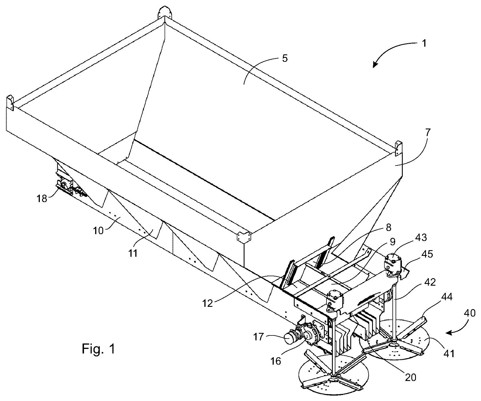
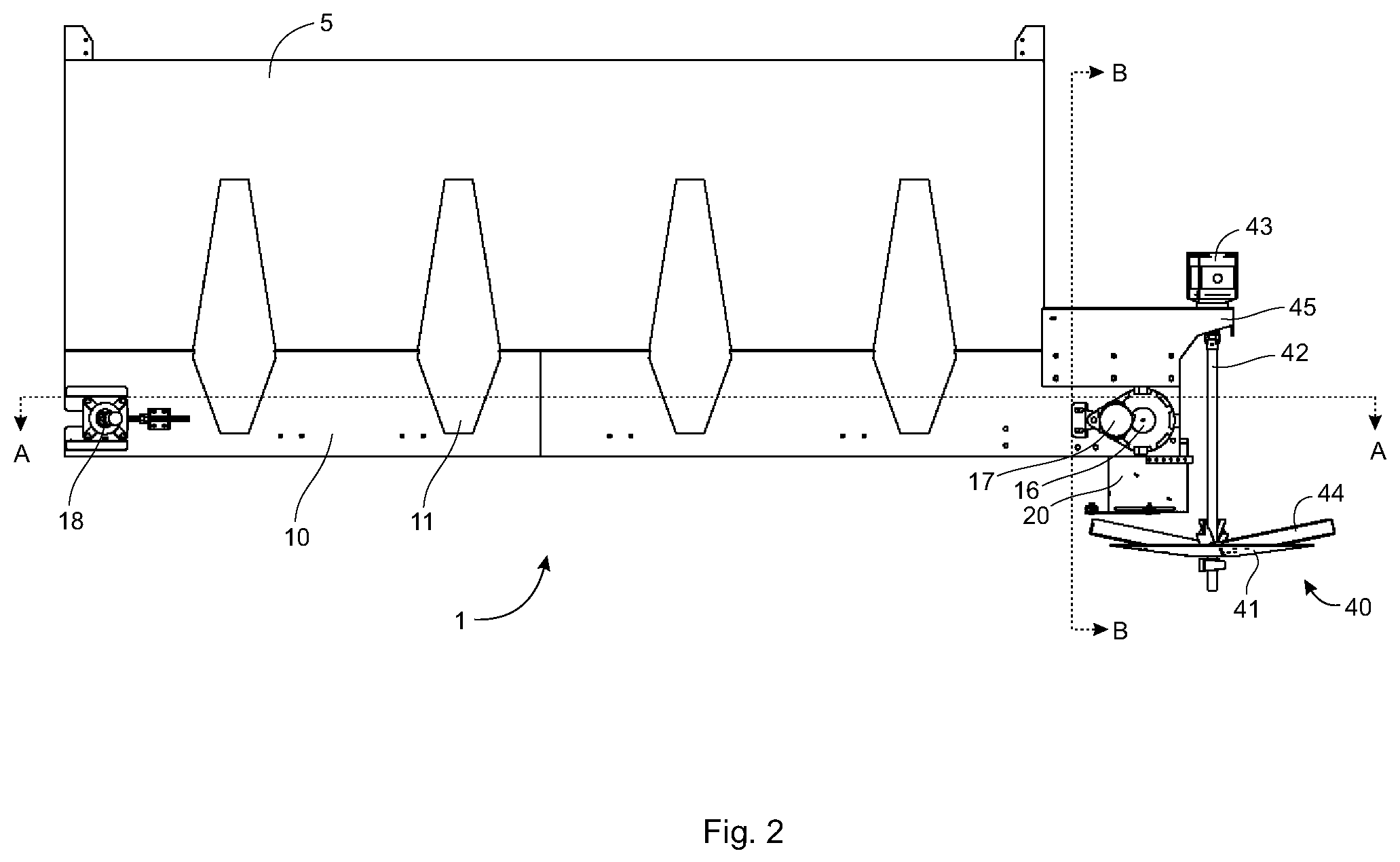
[0026] Referring to FIG. 1 to FIG. 8, one embodiment of a spinner spreader 1 comprises a hopper 5 mounted on a frame 10, the frame 10 comprising a plurality of support rails 11 (only one labeled) for supporting the hopper 5 on the frame 10. The frame 10 is mounted on a vehicle (not shown), for example a truck, a trailer and the like. The hopper 5 is designed to contain particulate material (e.g. fertilizer, fertilizer supplements, seed, sand, gravel, road salt, lime and the like) to be spread on a ground surface as the vehicle drives or is driven on or adjacent the ground surface.
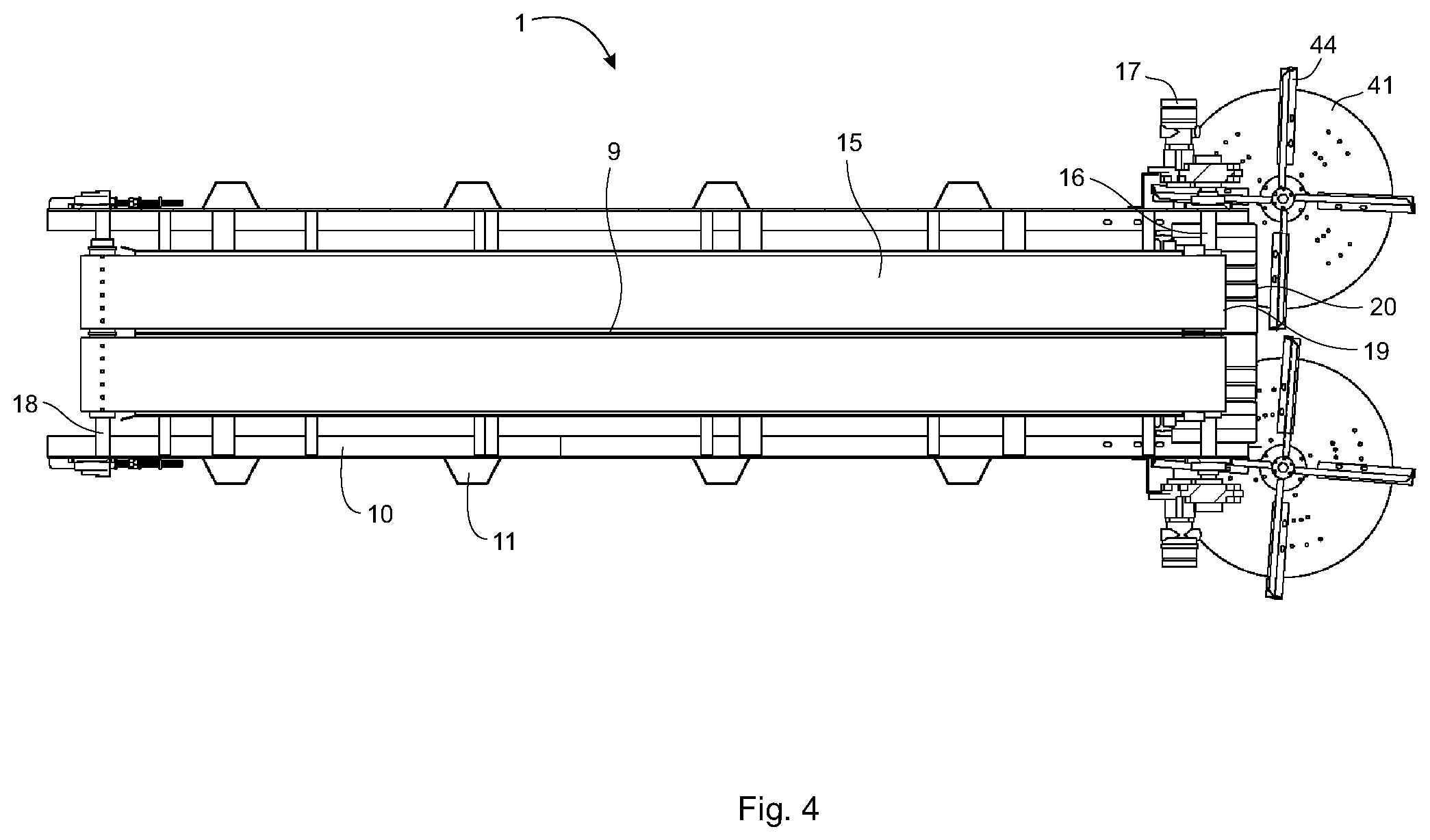
[0027] The spinner spreader 1 further comprises a pair of adjacent conveyor belts 15 (only one labeled) situated at a bottom of the hopper 5 and oriented longitudinally with respect to direction of motion of the vehicle. The conveyor belts 15 transport the particulate material in the hopper 5 toward a rear of the hopper 5, and therefore toward a rear of the spinner spreader 1. The conveyor belts 15 comprise endless belts rotationally mounted on transversely oriented drive rollers 16 (only one labeled) located proximate the rear of the spinner spreader 1, and on transversely oriented idler rollers 18 (only one labeled) located proximate a front of the spinner spreader 1. The rollers 16, 18 are rotatably mounted on the frame 10. There are separate drive and idler rollers 16, 18 for each conveyor belt 15 so that the conveyor belts may be driven independently, permitting driving the conveyor belts at different speeds, or even stopping one conveyor belt entirely, if desired. The two drive rollers 16 may be physically separated, or form a nested arrangement in which one of the drive rollers is hollow and a portion of the other of the drive rollers is mounted inside the hollow drive roller on bearings, permitting the two drive rollers to be operated independently. The same kind of nested arrangement may be utilized with the idler rollers 18. The drive rollers 16 are driven by hydraulic motors 17 (only one labeled) mounted on the frame 10. The conveyor belts 15 extend rearwardly past a rear wall 7 of the hopper 5 transporting the particulate material out of the hopper 5 through a hopper outlet 8 into a transition box 12. A flow divider 9 situated between the two conveyor belts 15 in the hopper 5 and the transition box 12 keeps the particulate material separated into two flow paths.
[0028] Two sets 20 (only one labeled) of individually translatable sluices 21 (only one in each set labeled) are disposed below rear ends 19 of the conveyor belts 15 to receive the particulate material flowing off the rear ends 19 of the conveyor belts 15. One set 20 of sluices 21 is associated with one of the conveyor belts 15 and receives the particulate material from the one conveyor belt 15. The other set of sluices receives the particulate material from the other conveyor belt, thereby keeping the flow paths of particulate material separate. Each of the sets 20 is shown with four individual sluices 21, although the sets may comprise more or fewer sluices and/or each of the sets need not have the same number of sluices. In some embodiments, each set may have one, two, three, four, five, six or more sluices.
[0029] With specific reference to FIG. 5 and FIG. 8, each of the sluices 21 comprise substantially vertically oriented side walls 22. The sluices 21 have open tops, but are closed at a bottom and front thereof by an inclined floor 23. The floor 23 is inclined downwardly from front to rear so that the particulate material may flow freely out of open rear ends of the sluices 21. The open tops may comprise funnels 24 to guide particulate material from the conveyor belts 15 into the sluices 21 so that each sluice 21 receives a portion of the particulate material, each portion being substantially the same amount. The funnels atop the end sluices in each set of sluices may be flared outwardly from the sets of sluices to ensure that all of, or at least most of, the particulate material falling off the conveyor belts 15 enters the sluices 21.
[0030] With specific reference to FIG. 8, the sluices 21 are disposed transversely to one another to form a series of parallel channels. Each of the side walls 22 of each of the sluices 21 comprise a longitudinally oriented elongated slot 25 situated in the side wall 22 below the floor 23. All of the slots 25 in a given set of sluices are parallel to each other and transversely aligned so that a threaded rod 26 maybe inserted transversely through all of the slots 25 in the sluices of the given set thereby supporting all of the sluices in the given set on the rod 26. Loosening one or more nuts, for example one or both of nuts 29 (see FIG. 5, only one labeled) on the threaded rod permits the sluices 21 to translate longitudinally forward and backward on the rod 26 by virtue of the elongated slot 25. Once the sluices 21 have been moved to desired longitudinal positions, the nuts 29 may be tightened on the rod 26 to immobilize all of the sluices 21 in new longitudinal positions. Because each of the sluices 21 supported on the rod 26 are individual structures, the sluices 21 may be longitudinally positioned independently of each other.
[0031] The spinner spreader 1 further comprises deflection plates 30 (only one labeled) mounted on the frame 10 to a rear of the sets 20 of sluices 21. The deflection plates 30 downwardly deflects the particulate material exiting from the open rear ends of the sluices 21.
[0032] The spinner spreader 1 further comprises a pair of adjacent spinner assemblies 40 (only one labeled) mounted on the frame 10 at the rear of the spinner spreader 1 behind the hopper 5 and below the sluices 21. If desired, the spinner assemblies may be mounted on a side of or in front of the hopper, with the sluices and conveyor belts positioned accordingly, but mounting the spinner assemblies behind the hopper is more typical in the art. Each spinner assembly 40 comprises a spinner disc 41 having a slightly concave upper surface that receives the particulate material from one set 20 of the sluices 21. Each spinner assembly 40 comprises a substantially vertically oriented spinner drive shaft 42 attached to a center of the spinner disc 41 and to a spinner drive motor 43. The spinner drive motor 43 is mounted on a spinner motor mount 45 mounted on the frame 10. Operation of the spinner drive motor 43 causes the spinner disc 41 to rotate in a plane parallel to the ground surface. Particulate material from the sluices 21 landing on the spinner disc 41 is propelled horizontally off the spinner disc 41 under the influence of centripetal force to be broadcast outwardly from the spinner spreader 1. The upper surface of the spinner disc 41 further comprises radially oriented fins 44, which assist with propelling the particulate material off the disc 41. The fins 44 may be designed to enhance throw distance and uniformity of spread pattern of the particulate material. While four fins 44 per spinner disc 41 are illustrated, each spinner disc 41 may comprise fewer or more fins, for example, each spinner disc 41 may comprise one, two, three, four, five, six or more fins.
[0033] The particulate material transported by one of the conveyor belts 15 through one set 20 of the sluices 21 is delivered to one of the spinner discs 41, while the other spinner disc of the pair receives the particulate material transported by the other of the conveyor belts through the other set of sluices. Because the longitudinal position of the spinner discs 41 is fixed, longitudinal translation of an individual sluice 21 results in the portion of particulate material from the individual sluice 21 to fall on the corresponding spinner disc 41 at a different radial position on the disc 41. Thus, swath control of the particulate material broadcast from each spinner disc 41 can be controlled independently for each disc 41 by independently controlling speed of the conveyor belts 15, longitudinal position of each sluice 21 in each set 20 of sluices 21, and rotational speed of each disc 41.
[0034] While a pair of conveyor belts, two sets of sluices and a pair of spinner assemblies are illustrated in the embodiment shown in the Figures, it is understood that the spinner spreader may comprise one or more conveyor belt, one or more set of sluices and/or one or more spinner assembly, where one or more may be, for example, one, two, three, four or more.
[0035] Referring to FIG. 9 to FIG. 12, the spinner spreader 1 provides improved control over spread pattern of the particulate material being broadcast by the spreader 1.
[0036] FIG. 9 illustrates a division of particulate material spread pattern 50 (individually labeled as 50a, 50b, 50c, 50d, 50e, 50f, 50g, 50h for the particle spread pattern from each sluice) and particle trajectories 60 (individually labeled as 60a, 60b, 60c, 60d, 60e, 60f, 60g, 60h for the trajectory from each sluice) produced by the spinner spreader 1 when all of the sluices 21 (individually labeled as 21a, 21b, 21c, 21d, 21e, 21f, 21g, 21h) are at the same longitudinal position. The sluices 21 are in two sets 20 of sluices, the sets 20 individually labeled as left set 20a and right set 20b. The sluices 21a, 21b, 21c, 21d are in the left set 20a, while the sluices 21d, 21e, 21f, 21g, 21h are in the right set 20b. The individual particle spread patterns 50a, 50b, 50c, 50d, 50e, 50f, 50g, 50h correspond to the individual trajectories 60a, 60b, 60c, 60d, 60e, 60f, 60g, 60h, respectively, which correspond to the individual sluices 21a, 21b, 21c, 21d, 21e, 21f, 21g, 21h, respectively. Particle flow paths from each sluice 21a, 21b, 21c, 21d, 21e, 21f, 21g, 21h are illustrated in dashed lines.
[0037] Still referring to FIG. 9, particulate material flowing out of the sluices 21 is delivered to the spinner discs 41 (individually labeled as left disc 41a and right disc 41b) to be broadcast to the ground following the illustrated trajectories 60. The left disc 41a broadcasts particulate material delivered by the left set 20a of sluices and the right disc 41b broadcasts particulate material delivered by the right set 20b of sluices. The particulate material delivered from one of the sluices in one set of sluices is dropped on the associated spinner disc at a different radial distance from a center of the spinner disc than the particulate material delivered from the other of the sluices in that set. For example, the particulate material from the outermost sluice 21a in the left set 20a is dropped on the left disc 41a proximate a center 48a of the left disc 41a. In comparison, the particulate material from the innermost sluice 21d in the left set 20a is dropped on the left disc 41a proximate a periphery 49a of the left disc 41a. Consequently, the particulate material from the outermost sluice 21a spends more time on the left disc 41a and has a more rearward trajectory 60a compared to the particulate material from the innermost sluice 21d when the respective particulate materials are finally broadcast by the spinning left disc 41a. The two middle sluices 21b, 21c deliver particulate material at different radial positions on the left disc 41a, which are intermediate between the more central position of the particulate material from the outermost sluice 21a and the more peripheral position of the particulate material from the innermost sluice 21d. An equivalent arrangement applies to the right disc 41b having a center 48b and a periphery 49b, and servicing the right set 20b.
[0038] As can be seen in FIG. 9, the arrangements of sluices 21 and spinner discs 41 described above can provide a uniform spread pattern 50 of particulate material through an angle of about 240.degree. behind the spreader 1.
[0039] The trajectory and spread pattern of particulate material delivered from an individual sluice is affected by the rotational speed of the spinner discs. Thus, the integrity of the spread pattern illustrated in FIG. 9 would be disrupted if an operator wants to alter the rotational speed of one or more of the spinner discs. For example, with reference to FIG. 10A, FIG. 10B and FIG. 10C, increasing the rotational speed of the right disc 41b (FIG. 10B) in comparison to a `normal` rotational speed (FIG. 10A) causes the particulate material delivered to the right disc 41b from the sluice 21e to be broadcast from the right disc 41b at a position transversely rightward from the position the particulate material is delivered at the `normal` rotational speed of the right disc 41b. Thus, the trajectory 60e and the spread pattern 50e of the particulate material delivered by the sluice 21e are skewed to the right when the rotational speed of the right disc 41b is increased (compare FIG. 10A to FIG. 10B). Conversely, decreasing the rotational speed of the right disc 41b (FIG. 10C) in comparison to a `normal` rotational speed (FIG. 10A) causes the particulate material delivered to the right disc 41b from the sluice 21e to be broadcast from the right disc 41b at a position transversely leftward from the position the particulate material is delivered at the `normal` rotational speed of the right disc 41b. Thus, the trajectory 60e and the spread pattern 50e of the particulate material delivered by the sluice 21e are skewed to the left when the rotational speed of the right disc 41b is decreased (compare FIG. 10A to FIG. 10C).
[0040] The trajectory and spread pattern of particulate material delivered from an individual sluice may be altered by adjusting position of the individual sluice forward or rearward (i.e. longitudinally) with respect to the other sluices. Independent adjustment of the longitudinal position of an individual sluice adjusts the radial position at which the particulate material from the individual sluice is dropped on the spinner disc, because longitudinal position of the spinner disc remains fixed. The ability to independently adjust the longitudinal position of each sluice permits compensating for changes in the rotational speed of one or more of the spinner discs to maintain spread pattern integrity. For example, with reference to FIG. 11A, FIG. 11B and FIG. 11C, rearwardly translating the sluice 21e (FIG. 11B) with respect to the other sluices causes the particulate material to drop on the right disc 41b radially closer to the center 48b than when the sluice 21e is in a `normal` longitudinal position (FIG. 11A). The particulate material therefore resides for a longer period of time on the spinning right disc 41b before being broadcast, resulting in the particulate material being broadcast in a particle trajectory 60e that is skewed to the right (compare FIG. 11A to FIG. 11B). As a result, the spread pattern 50e of the particulate material from the sluice 21e is also skewed to the right (compare FIG. 11A to FIG. 11B). Conversely, forwardly translating the sluice 21e (FIG. 11C) with respect to the other sluices causes the particulate material to drop on the right disc 41b radially closer to the periphery 49b than when the sluice 21e is in a `normal` longitudinal position (FIG. 11A). The particulate material therefore resides for a shorter period of time on the spinning right disc 41b before being broadcast, resulting in the particulate material being broadcast in a particle trajectory 60e that is skewed to the left (compare FIG. 11A to FIG. 11C). As a result, the spread pattern 50e of the particulate material from the sluice 21e is also skewed to the left (compare FIG. 10A to FIG. 11C). Particle flow path from the sluice 21e is illustrated with a dashed line in FIG. 11A, FIG. 11B and FIG. 11C. FIG. 11A, FIG. 11B and FIG. 11C illustrate that trajectory and spread pattern of the particulate material delivered from any particular sluice can be skewed left or right by altering the longitudinal position of the particular sluice.
[0041] Deliberate control of the longitudinal position of one or more of the sluices, the rotational speed of one or more of the spinner discs and the speed of one or more of the conveyor belts can be used to develop custom spread patterns for the particulate material. The rotational speed of the spinner discs controls rotational positions at which the particulate material is broadcasted from the spinner discs. The speed of the conveyor belts controls rates at which the particulate material is delivered to the spinner discs. FIG. 12 illustrates one possibility in which particle spread pattern is manipulated to switch off one of eight broadcast sections while maintaining a uniform spread pattern in the other seven broadcast sections. With reference to FIG. 12, the left set 20a of sluices and the right set 20b of sluices receive particulate material from a left conveyor belt 15a and a right conveyor belt 15b, respectively. The left set 20a of sluices and the right set 20b of sluices deliver the particulate material to the left disc 41a and the right disc 41b, respectively. The particulate material is normally broadcast into broadcast sections. The broadcast sections comprise four left-side sections 70a, 70b, 70c, 70d on a left side of the spreader 1, the four left-side sections 70a, 70b, 70c, 70d each correlating to the four sluices 21a, 21b, 21c, 21d (see FIG. 9), respectively, of the left set 20a of sluices. Likewise, the broadcast sections comprise four right-side sections 70e, 70f, 70g, 70h on a right side of the spreader 1, the four right-side sections 70e, 70f, 70g, 70h each correlating to the four sluices 21e, 21f, 21g, 21h (see FIG. 9), respectively, of the right set 20b of sluices. However, it may be desirable in some applications to switch off broadcasting the particulate material to section 70h while maintaining a uniform spread pattern across the other seven sections 70a, 70b, 70c, 70d, 70e, 70f, 70g. To accomplish such a custom spread pattern, the left conveyor belt 15a and the left disc 41a may be operated at normal speeds with the left set 20a of sluices in the normal longitudinal positions, thereby delivering 1 unit of particulate material to each of the four left-side sections 70a, 70b, 70c, 70d. On the right side, the right conveyor belt 15b may be operated at three-quarters of the normal speed, the right disc 41b may be operated at lower rotational speed and the right set 20b of sluices may be translated rearwardly. The lower rotational speed of the right disc 41b and the rearward translation of the right set 20b of sluices are balanced so that section 70h receives no particulate material, and the other three right-side sections 70e, 70f, 70g each receive the same amount of particulate material as each of the left-side sections (i.e. 1 unit), but each of the three right-side sections 70e, 70f, 70g receive particulate from two of the sluices of the right set 20b of sluices. Particle flow paths from each sluice are illustrated in dashed lines. Thus, section 70e receives 0.75 unit of particulate material from the sluice 21e and 0.25 unit of particulate material from the sluice 21f; section 70f receives 0.5 unit of particulate material from the sluice 21f and 0.5 unit of particulate material from the sluice 21g; section 70g receives 0.25 unit of particulate material from the sluice 21g and 0.75 unit of particulate material from the sluice 21h; and, section 70h receives no particulate material. Each of the sluices 21e, 21f, 21g, 21h of the right set 20b of sluices delivers a total of 0.75 unit because the right conveyor belt 15b is operated at three-quarters of the normal speed. However, the particulate material delivered by each of the four sluices 21e, 21f, 21g, 21h is divided between the three right-side sections 70e, 70f, 70g as a result of balancing the lower rotational speed of the right disc 41b with the rearward longitudinal translation of the right set 20b of sluices. Because the longitudinal position of each sluice is independently adjustable, it is possible to create many different spread patterns for a variety of different applications and situations by balancing longitudinal sluice positions, rotational speeds of the spinner discs and operating speeds of the conveyor belts.
[0042] The novel features will become apparent to those of skill in the art upon examination of the description. It should be understood, however, that the scope of the claims should not be limited by the embodiments, but should be given the broadest interpretation consistent with the wording of the claims and the specification as a whole.
* * * * *
D00000
D00001
D00002
D00003
D00004
D00005
D00006
D00007
D00008
D00009
D00010
D00011
D00012

XML
uspto.report is an independent third-party trademark research tool that is not affiliated, endorsed, or sponsored by the United States Patent and Trademark Office (USPTO) or any other governmental organization. The information provided by uspto.report is based on publicly available data at the time of writing and is intended for informational purposes only.
While we strive to provide accurate and up-to-date information, we do not guarantee the accuracy, completeness, reliability, or suitability of the information displayed on this site. The use of this site is at your own risk. Any reliance you place on such information is therefore strictly at your own risk.
All official trademark data, including owner information, should be verified by visiting the official USPTO website at www.uspto.gov. This site is not intended to replace professional legal advice and should not be used as a substitute for consulting with a legal professional who is knowledgeable about trademark law.