Undulated Interlocking Housing-endplate Interface Geometry
Ouweleen; Philip M. ; et al.
U.S. patent application number 16/487209 was filed with the patent office on 2020-12-10 for undulated interlocking housing-endplate interface geometry. This patent application is currently assigned to CUMMINS FILTRATION IP, INC.. The applicant listed for this patent is CUMMINS FILTRATION IP, INC.. Invention is credited to Robert A. Bannister, Joshua Crooks, Sean M. Grabein, Zemin Jiang, Mark J. Johnson, Karthik Kothakota, Ted S. Loftis, Connor D. Oren, Philip M. Ouweleen, Brian M. Palmer, Mano Raj Sekar, Aaron M. Wells.
| Application Number | 20200384395 16/487209 |
| Document ID | / |
| Family ID | 1000005062120 |
| Filed Date | 2020-12-10 |


View All Diagrams
| United States Patent Application | 20200384395 |
| Kind Code | A1 |
| Ouweleen; Philip M. ; et al. | December 10, 2020 |
UNDULATED INTERLOCKING HOUSING-ENDPLATE INTERFACE GEOMETRY
Abstract
A filtration system having an undulated interlocking housing-endplate interface geometry is described. In the filtration system, a filter element endplate and a filter housing component (e.g., a shell housing, a filter mounting head, etc.) meet at an interface. The filter housing component includes an undulating or repeating pattern that meshes with a matching undulating or repeating pattern on the endplate of the filter element. The undulating or repeating pattern prevents the filter element from freely rotating with respect to the filter housing component of the filtration system.
| Inventors: | Ouweleen; Philip M.; (Cookeville, TN) ; Jiang; Zemin; (Cookeville, TN) ; Loftis; Ted S.; (Cookeville, TN) ; Kothakota; Karthik; (Cookeville, TN) ; Sekar; Mano Raj; (Columbus, IN) ; Johnson; Mark J.; (Cookeville, IN) ; Wells; Aaron M.; (Cookeville, TN) ; Bannister; Robert A.; (Ames, IA) ; Crooks; Joshua; (Cookeville, TN) ; Palmer; Brian M.; (Cookeville, TN) ; Grabein; Sean M.; (Rock Island, TN) ; Oren; Connor D.; (Cookeville, TN) | ||||||||||
| Applicant: |
|
||||||||||
|---|---|---|---|---|---|---|---|---|---|---|---|
| Assignee: | CUMMINS FILTRATION IP, INC. Columbus IN |
||||||||||
| Family ID: | 1000005062120 | ||||||||||
| Appl. No.: | 16/487209 | ||||||||||
| Filed: | February 20, 2018 | ||||||||||
| PCT Filed: | February 20, 2018 | ||||||||||
| PCT NO: | PCT/US2018/018724 | ||||||||||
| 371 Date: | August 20, 2019 |
Related U.S. Patent Documents
| Application Number | Filing Date | Patent Number | ||
|---|---|---|---|---|
| 62461497 | Feb 21, 2017 | |||
| Current U.S. Class: | 1/1 |
| Current CPC Class: | B01D 2201/4053 20130101; B01D 2201/52 20130101; B01D 35/30 20130101; B01D 2201/295 20130101; B01D 2201/4076 20130101; B01D 2265/026 20130101; B01D 46/009 20130101; B01D 2265/021 20130101; B01D 29/15 20130101; B01D 46/2414 20130101; B01D 2201/4092 20130101 |
| International Class: | B01D 35/30 20060101 B01D035/30; B01D 29/15 20060101 B01D029/15; B01D 46/00 20060101 B01D046/00; B01D 46/24 20060101 B01D046/24 |
Claims
1. A filter element comprising: filter media; and a first endplate coupled to the filter media, the first endplate comprising: a top surface, a bottom surface parallel to and displaced from the top surface, a central opening passing through the top surface and the bottom surface, at least one inlet, and a first undulated wall positioned between the top surface and the bottom surface, the first undulated wall having a pattern that defines an outer circumferential uneven surface structured to mesh with a matching pattern of a shell housing when the filter element is installed in the shell housing.
2. The filter element of claim 1, wherein the pattern includes a plurality of interlocking features.
3. The filter element of claim 1, wherein the first endplate further comprises a gasket retaining lip and a gasket retaining wall, the gasket retaining wall perpendicular to the top surface, the gasket retaining lip parallel to the top surface, the gasket retaining lip connecting the first undulated wall and the gasket retaining wall, the gasket retaining lip and the gasket retaining wall forming a first portion of a U-shaped channel that receives an outer seal member.
4. The filter element of claim 3, wherein the first endplate further comprises an inner gasket retaining lip, a first gasket retaining wall, and a second gasket retaining wall, the first gasket retaining wall and the second gasket retaining wall perpendicular to the top surface and spaced inward from the gasket retaining wall, the inner gasket retaining lip and first gasket retaining wall and the second gasket retaining wall forming a second U-shaped channel that receives an inner seal member.
5. The filter element of claim 4, wherein a first space is defined between the outer seal member and the inner seal member, the first space in fluid communication with the at least one inlet and a second space is defined inside of the inner seal member, the second space in fluid communication with the central opening.
6. A filtration system comprising: a filter mounting head having a fluid inlet and a fluid outlet; a shell housing removably coupled to the filter mounting head through a threaded connection, the shell housing defining a central compartment, the shell housing including a second undulating wall having the matching pattern; and the filter element of claim 1 positioned within the central compartment such that first undulated wall meshes with the second undulated wall.
7. The filtration system of claim 6, wherein filter element is rotationally locked with respect to the shell housing.
8. The filtration system of claim 6, wherein the first endplate is inscribed with the pattern.
9. The filtration system of claim 6, wherein the first endplate circumscribes the pattern.
10. The filtration system of claim 6, wherein the first endplate includes a raised tab extending from a top surface of the first endplate, the raised tab received in a circular channel of the filter mounting head.
11. The filter element of claim 1, wherein the top surface comprises a nutplate and the bottom surface comprises an endplate; the nutplate comprises a top nutplate surface and a bottom nutplate surface parallel to and displaced from the top nutplate surface, the first undulated wall disposed between the top nutplate surface and the bottom nutplate surface; and the endplate comprises a top endplate surface and a bottom endplate surface parallel to and displaced from the top endplate surface, the top endplate surface substantially parallel to the bottom nutplate surface, the top endplate surface spaced away from the bottom nutplate surface by a fluid passageway.
12. The filter element of claim 11, wherein the nutplate further comprises a plurality of ribs between the top nutplate surface and the bottom nutplate surface, each of the plurality of ribs radially disposed from the central opening to the first undulated wall, and at least one opening is disposed between the plurality of ribs and in fluid communication with the at least one inlet.
13. The filter element of claim 11, wherein the top nutplate surface further comprises a gasket retaining lip and a gasket retaining wall, the gasket retaining wall perpendicular to the top nutplate surface, the gasket retaining lip parallel to the top nutplate surface, the gasket retaining lip connecting the first undulated wall and the gasket retaining wall, the gasket retaining lip and the gasket retaining wall forming a first portion of a U-shaped channel that receives an outer seal member.
14. A filtration system comprising: a filter mounting head having a fluid inlet and a fluid outlet; a filter element comprising: filter media; and a first endplate coupled to the filter media, the first endplate comprising: a top surface, a bottom surface parallel to and displaced from the top surface, a central opening passing through the top surface and the bottom surface, at least one inlet, and a first undulated wall positioned between the top surface and the bottom surface, the first undulated wall having a pattern that defines an outer circumferential uneven surface structured to mesh with a matching pattern of a shell housing when the filter element is installed in the shell housing, the top surface comprises a nutplate and the bottom surface comprises an endplate; the nutplate comprising a top nutplate surface and a bottom nutplate surface parallel to and displaced from the top nutplate surface, the first undulated wall disposed between the top nutplate surface and the bottom nutplate surface; and the endplate comprising a top endplate surface and a bottom endplate surface parallel to and displaced from the top endplate surface, the top endplate surface substantially parallel to the bottom nutplate surface, the top endplate surface spaced away from the bottom nutplate surface by a fluid passageway; a shell housing removably coupled to the filter mounting head through a threaded connection, the shell housing defining a central compartment, the shell housing including a second undulating wall having the matching pattern, the filter element positioned within the central compartment such that first undulated wall meshes with the second undulated wall.
15. The filtration system of claim 14, wherein the shell housing further comprises a endplate lip disposed below the second undulating wall, the endplate lip engaging with a portion of the bottom nutplate surface.
16. The filtration system of claim 14, wherein filter element is rotationally locked with respect to the shell housing.
17. The filtration system of claim 14, wherein the first endplate is inscribed with the pattern.
18. The filtration system of claim 14, wherein the first endplate circumscribes the pattern.
19. A filter element comprising: filter media; and a first endplate coupled to the filter media, the first endplate comprising: a top surface, a bottom surface parallel to and displaced from the top surface, a central opening passing through the top surface and the bottom surface, at least one inlet, a flange axially protruding away from and perpendicular to the bottom surface, and a first undulated wall positioned on a surface of the flange, the first undulated wall protruding radially away from the flange and having a pattern that defines an outer circumferential surface structured to mesh with a matching pattern of a shell housing when the filter element is installed in the shell housing.
20. The filter element of claim 19, wherein the flange is radially flexible toward the filter media.
21. A filtration system comprising: a filter mounting head having a fluid inlet and a fluid outlet; a filter element comprising: filter media; and a first endplate coupled to the filter media, the first endplate comprising: a top surface, a bottom surface parallel to and displaced from the top surface, a central opening passing through the top surface and the bottom surface, at least one inlet, a flange axially protruding away from and perpendicular to the bottom surface, and a first undulated wall positioned on a surface of the flange, the first undulated wall protruding radially away from the flange and having a pattern that defines an outer circumferential surface structured to mesh with a matching pattern of a shell housing when the filter element is installed in the shell housing; and a shell housing removably coupled to the filter mounting head through a threaded connection, the shell housing defining a central compartment, the shell housing including a second undulating wall having the matching pattern, the second undulating wall comprising a shell channel below a wall retaining ridge, the filter element positioned within the central compartment such that first undulated wall meshes with the second undulated wall when the first undulated wall is positioned in the shell housing below the wall retaining ridge.
22. The filtration system of claim 21, further comprising a biasing member disposed on second endplate, the second endplate coupled to the filter media opposite the first endplate, the biasing member provides a biasing force on filter element causing the first undulated wall to contact the wall retaining ridge and remain in the shell channel.
Description
CROSS-REFERENCE TO RELATED PATENT APPLICATION
[0001] The present application claims the benefit of priority to U.S. Provisional Patent Application No. 62/461,497, filed Feb. 21, 2017 and the contents of which are incorporated herein by reference in its entirety.
TECHNICAL FIELD
[0002] The present application relates to filtration systems.
BACKGROUND
[0003] Internal combustion engines generally combust a mixture of fuel (e.g., gasoline, diesel, natural gas, etc.) and air. Lubrication oil is also supplied to the engine to lubricate the various moving components of the engine. Either prior to entering the engine or during engine operation, the intake air, fuel, lubrication oil, and other fluids are typically passed through filtration systems to remove contaminants (e.g., dust, water, oil, etc.) from the fluids. The filtration systems include filter elements having filter media. As the fluid passes through the filter media, the filter media removes at least a portion of the contaminants in the fluid.
[0004] Oftentimes, the filter elements in the filtration systems require periodic replacement (e.g., as the pressure drop across the filter media increases). As cost saving measures, some technicians install counterfeit, non-genuine, or non-authorized filter elements into the filtration system (collectively referred to as "non-authorized" filter elements). Such non-authorized filter elements may not conform to original manufacturer quality, performance and safety parameters. For example, the non-authorized filter elements may utilize sub-optimal sealing technology, suboptimal filter media, poor or improper assembly, or the like. Accordingly, non-authorized filter elements may allow more contaminants to pass through the filtration system, thereby damaging the downstream components (e.g., the internal combustion engine, pumps, turbochargers, etc.).
SUMMARY
[0005] Various example embodiments relate to filter elements and filter housings that include an undulated interlocking housing-endplate interface geometry. One example embodiment relates to a filter element. The filter element includes filter media and a first endplate coupled to the filter media. The first endplate includes a top surface and a bottom surface parallel to and displaced from the top surface. The first endplate includes a central opening passing through the top surface and the bottom surface. The first endplate further includes at least one inlet. The first endplate further includes a first undulated wall positioned between the top surface and the bottom surface. The first undulated wall includes a repeating pattern that defines an outer circumferential uneven surface structured to mesh with a matching repeating pattern of a shell housing when the filter element is installed in the shell housing.
[0006] Another example embodiment relates to a filtration system. The filtration system includes a filter mounting head having a fluid inlet and a fluid outlet. The filtration system further includes a shell housing removably coupled to the filter mounting head through a threaded connection. The shell housing defines a central compartment. The shell housing includes a second undulating wall having the matching repeating pattern. The filtration system further includes a filter element positioned within the central compartment. The filter element includes filter media and a first endplate coupled to the filter media. The first endplate includes a top surface and a bottom surface parallel to and displaced from the top surface. The first endplate includes a central opening passing through the top surface and the bottom surface. The first endplate further includes at least one inlet. The first endplate further includes a first undulated wall positioned between the top surface and the bottom surface. The first undulated wall includes a repeating pattern that defines an outer circumferential uneven surface structured to mesh with the matching repeating pattern of the shell housing.
[0007] Another example embodiment relates to a filter element. The filter element includes filter media and a first endplate coupled to the filter media. The first endplate includes a top surface and a bottom surface parallel to and displaced from the top surface. The first endplate includes a central opening passing through the top surface and the bottom surface. The first endplate further includes at least one inlet. The first endplate further includes a first undulated wall positioned between the top surface and the bottom surface. The first undulated wall includes a repeating pattern that defines an outer circumferential uneven surface structured to mesh with a matching repeating pattern of a shell housing when the filter element is installed in the shell housing. The top surface includes a nutplate and the bottom surface includes an endplate. The nutplate includes a top nutplate surface and a bottom nutplate surface parallel to and displaced from the top nutplate surface. The first undulated wall is disposed between the top nutplate surface and the bottom nutplate surface. The endplate includes a top endplate surface and a bottom endplate surface parallel to and displaced from the top endplate surface. The top endplate surface is substantially parallel to the bottom nutplate surface. The top endplate surface is spaced away from the bottom nutplate surface by a fluid passageway.
[0008] Another example embodiment relates to a filtration system. The filtration system includes a filter mounting head having a fluid inlet and a fluid outlet. The filtration system further includes a shell housing removably coupled to the filter mounting head through a threaded connection. The shell housing defines a central compartment. The shell housing includes a second undulating wall having the matching repeating pattern. The filtration system further includes a filter element positioned within the central compartment. The filter element includes filter media and a first endplate coupled to the filter media. The first endplate includes a top surface and a bottom surface parallel to and displaced from the top surface. The first endplate includes a central opening passing through the top surface and the bottom surface. The first endplate further includes at least one inlet. The first endplate further includes a first undulated wall positioned between the top surface and the bottom surface. The first undulated wall includes a repeating pattern that defines an outer circumferential uneven surface structured to mesh with the matching repeating pattern of the shell housing. The top surface includes a nutplate and the bottom surface includes an endplate. The nutplate includes a top nutplate surface and a bottom nutplate surface parallel to and displaced from the top nutplate surface. The first undulated wall is disposed between the top nutplate surface and the bottom nutplate surface. The endplate includes a top endplate surface and a bottom endplate surface parallel to and displaced from the top endplate surface. The top endplate surface is substantially parallel to the bottom nutplate surface. The top endplate surface is spaced away from the bottom nutplate surface by a fluid passageway.
[0009] Another example embodiment relates to a filter element. The filter element includes filter media and a first endplate coupled to the filter media. The first endplate includes a top surface and a bottom surface parallel to and displaced from the top surface. The first endplate includes a central opening passing through the top surface and the bottom surface. The first endplate further includes at least one inlet. A flange axially protrudes away from and is perpendicular to the bottom surface. The first endplate further includes a first undulated wall positioned on a surface of the flange. The first undulated wall protrudes radially away from the flange and has a pattern that defines an outer circumferential surface structured to mesh with a matching repeating pattern of a shell housing when the filter element is installed in the shell housing.
[0010] Another example embodiment relates to a filtration system. The filtration system includes a filter mounting head having a fluid inlet and a fluid outlet. The filtration system further includes a shell housing removably coupled to the filter mounting head through a threaded connection. The shell housing defines a central compartment. The shell housing includes a second undulating wall having the matching repeating pattern. The filtration system further includes a filter element positioned within the central compartment The filter element includes filter media and a first endplate coupled to the filter media. The first endplate includes a top surface and a bottom surface parallel to and displaced from the top surface. The first endplate includes a central opening passing through the top surface and the bottom surface. The first endplate further includes at least one inlet. A flange axially protrudes away from and is perpendicular, or substantially perpendicular, to the bottom surface. The first endplate further includes a first undulated wall positioned on a surface of the flange. The first undulated wall protrudes radially away from the flange and has a pattern that defines an outer circumferential surface structured to mesh with a matching repeating pattern of a shell housing when the filter element is installed in the shell housing.
[0011] These and other features, together with the organization and manner of operation thereof, will become apparent from the following detailed description when taken in conjunction with the accompanying drawings, wherein like elements have like numerals throughout the several drawings described below.
BRIEF DESCRIPTION OF THE FIGURES
[0012] FIG. 1 shows a cross-sectional view of a filtration system according to an example embodiment.
[0013] FIG. 2 shows a cross-sectional view of the interaction between the first endplate and the shell housing of the filtration system of FIG. 1.
[0014] FIG. 3A shows a top view of a portion of the shell housing of the filtration system of FIG. 1.
[0015] FIG. 3B shows a perspective view of the portion of the shell housing of the filtration system of FIG. 1.
[0016] FIG. 4A shows a portion of a perspective view of a top side of the first endplate of the filtration system of FIG. 1.
[0017] FIG. 4B shows a portion of a perspective view of a bottom side of the first endplate of the filtration system of FIG. 1.
[0018] FIG. 5A shows a top view of the first endplate installed in the shell housing of the filtration system of FIG. 1.
[0019] FIG. 5B shows a close-up view of the first endplate installed in the shell housing of the filtration system of FIG. 1.
[0020] FIG. 6 shows a cross-sectional view of a non-authorized filter element being improperly installed in the filtration system of FIG. 1.
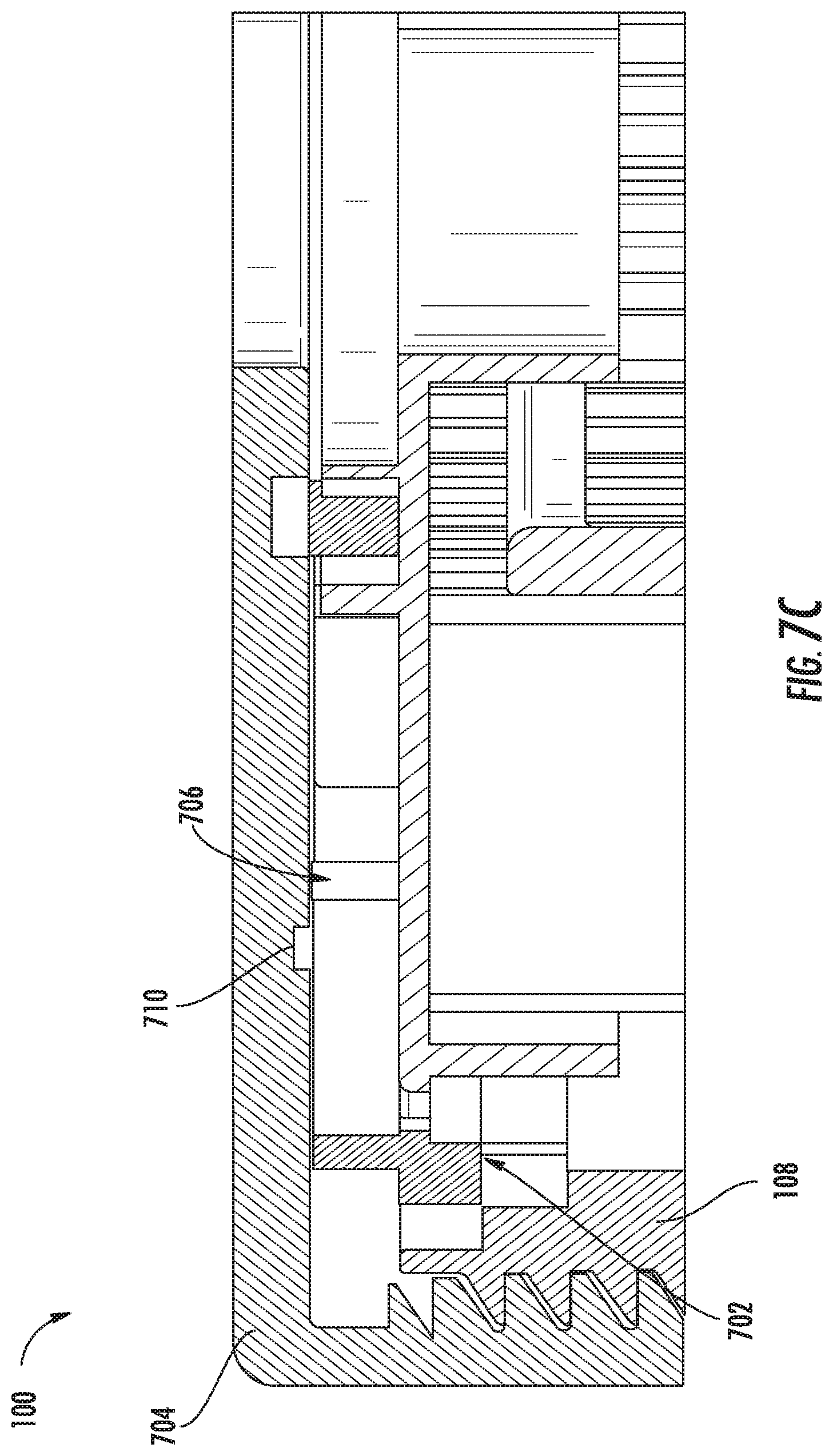
[0021] FIG. 7A shows a perspective view of a first endplate according to an example embodiment.
[0022] FIG. 7B shows a perspective view of a filter mounting head according to an example embodiment.
[0023] FIG. 7C shows a cross-sectional view of the first endplate of FIG. 7A interfacing with the filter mounting head of FIG. 7B.
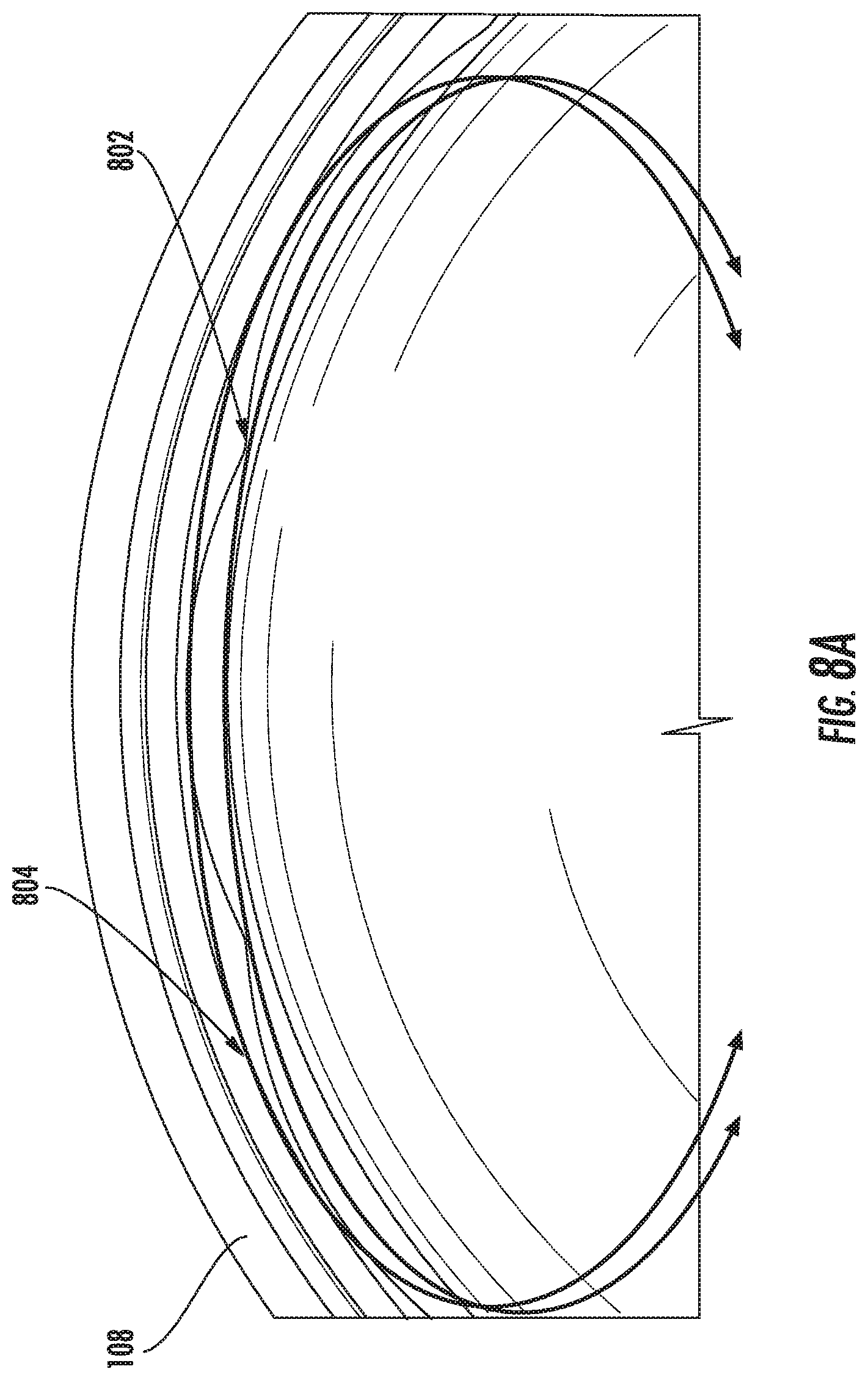
[0024] FIG. 8A shows a perspective view of different first endplates being mounted into a shell housing.
[0025] FIGS. 8B and 8C show views of a first arrangement of the first endplate of FIG. 8 mounted into the shell housing.
[0026] FIGS. 8D and 8E show views of a second arrangement of the first endplate of FIG. 8 mounted into the shell housing.
[0027] FIG. 9 shows a cross-sectional view of a filtration system according to an example embodiment.
[0028] FIG. 10A shows a perspective view of the shell housing of the filtration system of FIG. 9.
[0029] FIG. 10B shows a cross-sectional view of a portion of the shell housing of the filtration system of FIG. 9.
[0030] FIG. 11 shows a perspective view of the filter element of the filtration system of FIG. 9.
[0031] FIG. 12A shows a cross-sectional view of the first endplate of the filter element of the filtration system of FIG. 9.
[0032] FIG. 12B shows a perspective view of the first endplate of the filter element of the filtration system of FIG. 9.
[0033] FIG. 13 shows a perspective view of the first endplate installed in the shell housing of the filtration system of FIG. 9.
[0034] FIG. 14 shows a cross-sectional view of a filtration system according to another example embodiment.
[0035] FIG. 15A shows a perspective view of the shell housing of the filtration system of FIG. 14.
[0036] FIG. 15B shows a cross-sectional view of a portion of the shell housing of the filtration system of FIG. 14.
[0037] FIG. 16 shows a cross-sectional view of the filter element of the filtration system of FIG. 14.
[0038] FIG. 17 shows a cross-sectional view of a filtration system according to another example embodiment.
[0039] FIG. 18A shows a perspective view of the shell housing of the filtration system of FIG. 17.
[0040] FIG. 18B shows a cross-sectional view of a portion of the shell housing of the filtration system of FIG. 17.
[0041] FIG. 19 shows a perspective view of the filter element of the filtration system of FIG. 17.
[0042] FIG. 20A shows a cross-sectional view of the first endplate of the filter element of the filtration system of FIG. 17.
[0043] FIG. 20B shows a perspective view of the first endplate of the filter element of the filtration system of FIG. 17.
[0044] FIG. 21 shows a perspective view of the first endplate installed in the shell housing of the filtration system of FIG. 17.
DETAILED DESCRIPTION
[0045] Referring to the figures generally, a filtration system having an undulated interlocking housing-endplate interface geometry is described. In the filtration system, a filter element endplate and a filter housing component (e.g., a shell housing, a filter mounting head, etc.) meet at an interface. The interface may form a seal between the endplate and the filter housing component. The filter housing component includes an undulating or repeating pattern that meshes with a matching undulating or repeating pattern on the endplate of the filter element. The two undulating or repeating patterns "mesh" when the two patterns engage and lock in a similar manner as the teeth of two meshing gears thereby preventing substantial rotation of the endplate with respect to the filter housing component (i.e., preventing the endplate from rotating with respect to the filter housing component by more than five degrees in a given direction). In some arrangements, the undulating interlocking interface forms a seal between the filter housing component and the endplate. In some embodiments, the endplate with the undulating or repeating pattern may include an integrated nutplate. The endplate with the integrated nutplate can provide drop-in and drop-out assembly of the filter element into the filter housing. In other embodiments, the pattern on the endplate includes mesh protrusions (e.g., fingers) that interlock (e.g., snap) with a lip formed on the inside of the filter housing.
[0046] As will be appreciated, if a non-authorized filter element lacking the matching undulating pattern is attempted to be installed in or on the filter housing component, the non-authorized filter element may not fit against the filter housing component and/or may not form the appropriate seal with the filter housing component. Accordingly, the undulating or repeating pattern prevents non-authorized filter elements from being installed in the filtration system. Additionally, the undulating or repeating pattern prevents the filter element from freely rotating with respect to the filter housing component of the filtration system.
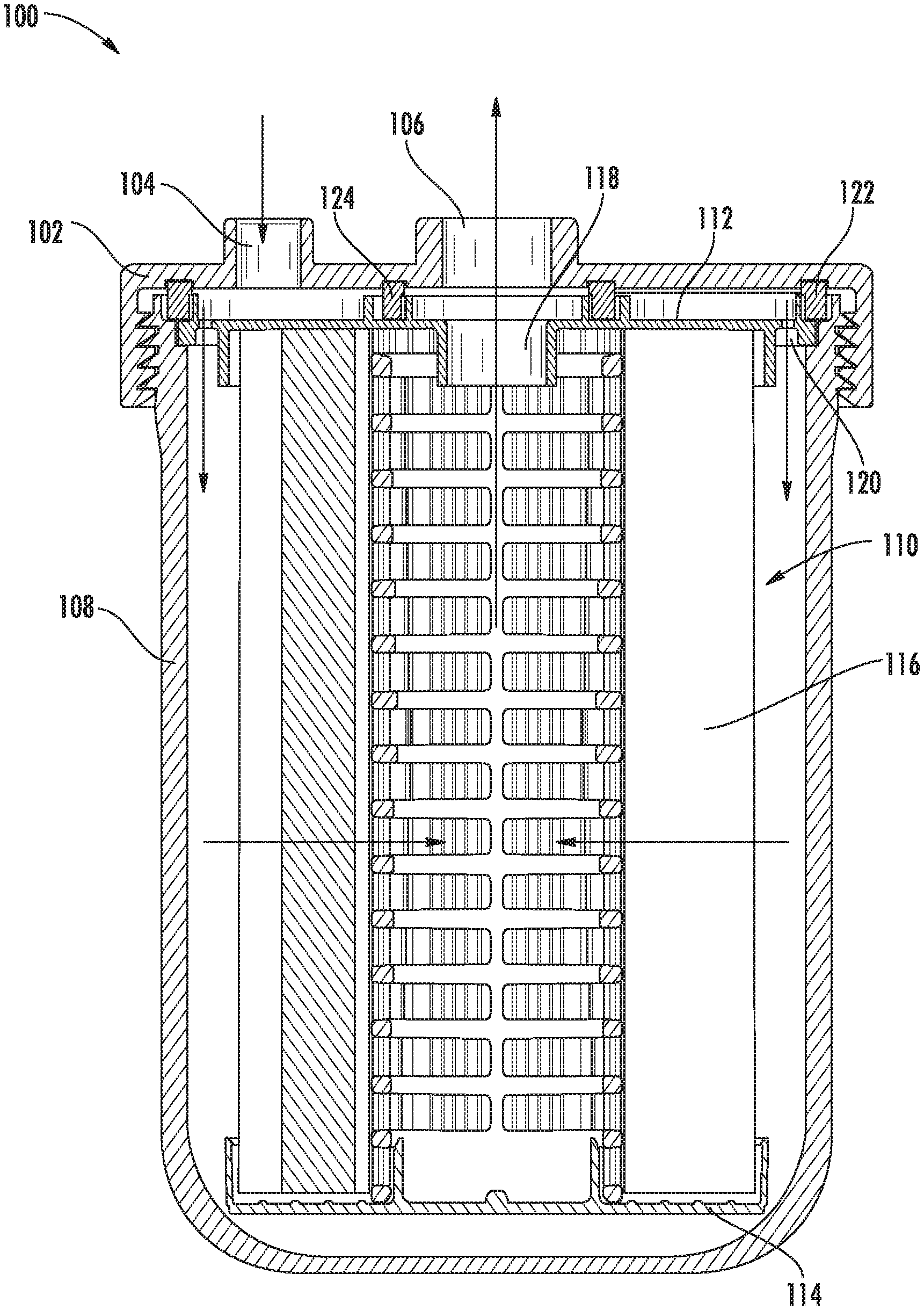
[0047] Referring to FIG. 1, a cross-sectional view of a filtration system 100 is shown according to an example embodiment. The filtration system 100 may be a fuel filtration system, a lubricant filtration system, a hydraulic fluid filtration system, a water filtration system, or the like. The filtration system 100 includes a filter mounting head 102 having an inlet 104 and an outlet 106. The filter mounting head 102 removably receives a shell housing 108 through a threaded connection. The shell housing 108 is substantially cylindrical in shape having an open top end adjacent to the filter mounting head 102 and a closed bottom end opposite the open top end. In some arrangements, the closed bottom end includes a closeable drain opening, a sensor port, or another opening that can be selectively sealed.
[0048] A filter element 110 is installed in the filtration system 100. The filter element 110 is received in a central compartment formed by the shell housing 108. The filter element 110 includes a first endplate 112, a second endplate 114, and filter media 116 positioned between the first endplate 112 and the second endplate 114. The filter media 116 is arranged in a cylindrical manner between the first endplate 112 and the second endplate 114. As shown in FIG. 1, the first endplate 112 is an open endplate that includes a central opening 118 in fluid communication with the outlet 106. The second endplate 114 is a closed endplate. The first endplate 112 includes at least one inlet opening 120 in fluid communication with the inlet 104. In some arrangements, the total inlet flow area created by the at least one inlet opening 120 is larger than the most restrictive design feature of the system receiving the fluid such that the inlet openings 120 are not the most restrictive design feature.
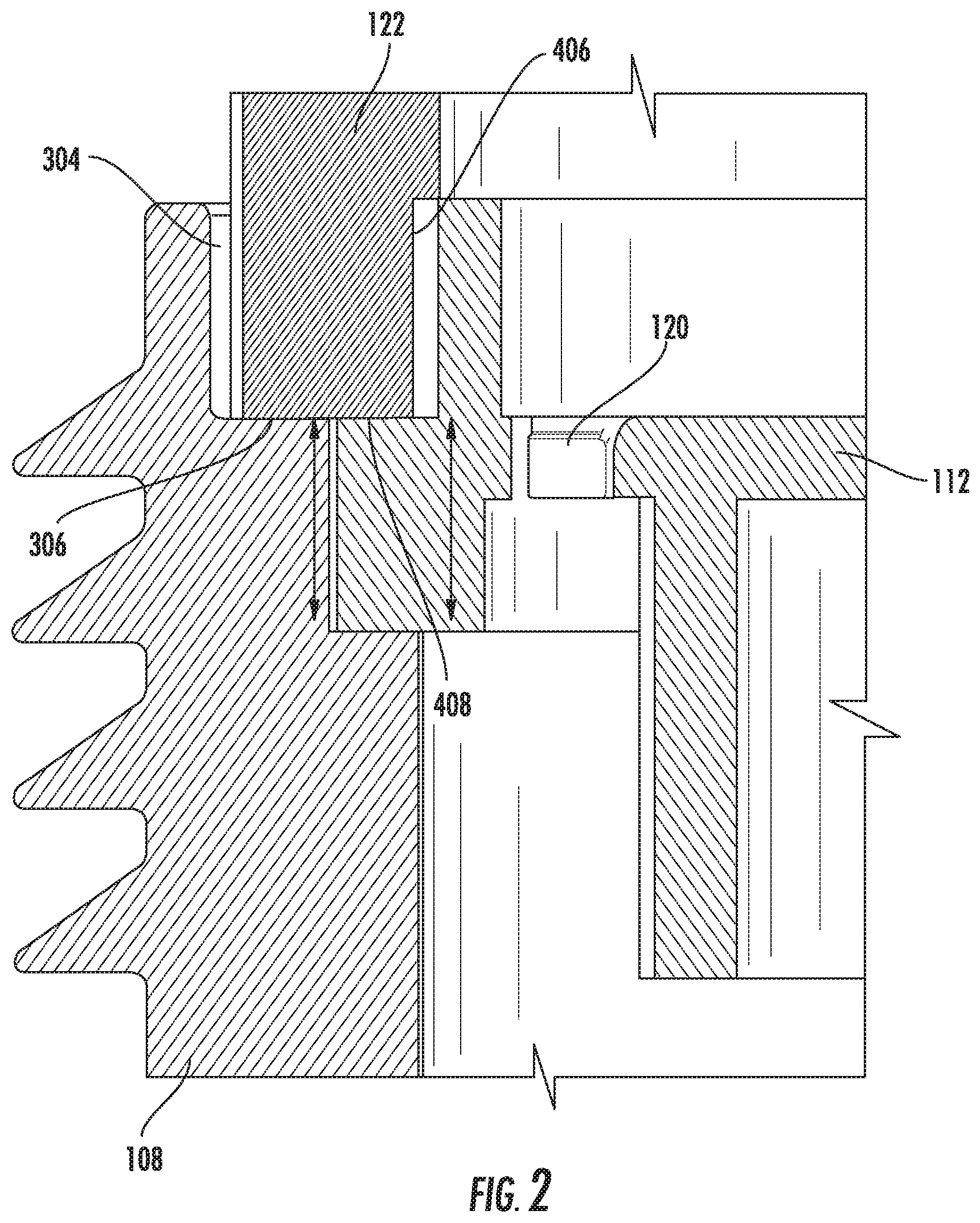
[0049] The filtration system 100 includes an outer seal member 122 and an inner seal member 124. The outer seal member 122 is supported in a U-shaped channel formed by the first endplate 112 and the shell housing 108 (e.g., as shown in FIG. 2, which shows a cross-sectional view of the interaction between the first endplate 112 and the shell housing 108). The inner seal member 124 is supported in a U-shaped channel formed by projections on the first endplate 112. When the filter element 110 and the shell housing 108 are installed in the filtration system 100 (e.g., as shown in FIG. 1), the outer seal member 122 and inner seal member 124 are pressed against the filter head and form seals. The space defined between the outer seal member 122 and the inner seal member 124 is in fluid communication with the inlet 104 and the inlet openings 120. The space inside of the inner seal member 124 is in fluid communication with the outlet 106 and the central opening 118. Accordingly, when the filter element 110 is installed in the filtration system (as shown in FIG. 1), fluid to be filtered flows through the inlet 104, through the inlet openings 120, through the filter media 116 in an outside-in flow direction, out the central opening 118, and out the outlet 106 as shown by the flow arrows of FIG. 1.
[0050] As described in further detail below with respect to FIGS. 3A through 6, the shell housing 108 and the first endplate 112 include matching undulated surfaces that mesh when the filter element 110 is installed in the shell housing 108. The matching undulated surfaces include a plurality of curves or shapes. The matching undulated surfaces prevent the filter element 110 from rotating with respect to the shell housing 108 during installation of the shell housing 108 to the filter mounting head 102. Additionally, the undulated surface of the shell housing 108 prevents a non-authorized filter element (e.g., a filter element without the matching undulated surface) from being installed in the shell housing 108 and ultimately installed in the filtration system 100.
[0051] Referring to FIGS. 3A and 3B, views of the shell housing 108 are shown. FIG. 3A shows a top view of a portion of the shell housing 108. FIG. 3B shows a perspective view of the same portion of the shell housing 108 shown in FIG. 3A. As described above with respect to FIG. 1, the shell housing 108 includes an open top end. The open top end is defined by a top surface 302, a gasket retaining wall 304, a gasket retaining lip 306, an undulated wall 308, and an endplate retaining lip 310. In some arrangements, the top surface 302, the gasket retaining lip 306, and the endplate retaining lip 310 are parallel, or substantially parallel, surfaces. In some arrangements, the gasket retaining wall 304 and the undulated wall 308 are perpendicular, or substantially perpendicular, to the top surface 302, the gasket retaining lip 306, and/or the endplate retaining lip 310. The gasket retaining wall 304 and the gasket retaining lip 306 define a first portion of the U-shaped channel (a first half of the U-shaped channel in one embodiment) that receives the outer seal member 122 (as described above with respect to FIGS. 1 and 2). The undulated wall 308 and the endplate retaining lip 310 receive the first endplate 112 when the filter element 110 is installed in the shell housing 108. The undulated wall 308 defines an inner circumferential uneven surface such that only filter elements with a complimentary undulated wall (e.g., the undulated wall 410 of the first endplate 112) can be retained in the shell housing 108. The undulated pattern that defines the undulated wall 308 may be continuous or intermittent throughout the inner circumference of the undulated wall 308. As used herein, "undulated" or "undulating" may refer to a repeating pattern or non-repeating pattern that may follow a wave pattern (e.g., a sinusoidal pattern), a flower pattern, a triangular pattern, a continuous pattern (e.g., raised surface), or any other pattern such that a mating pattern can mesh with the undulated or undulating pattern.
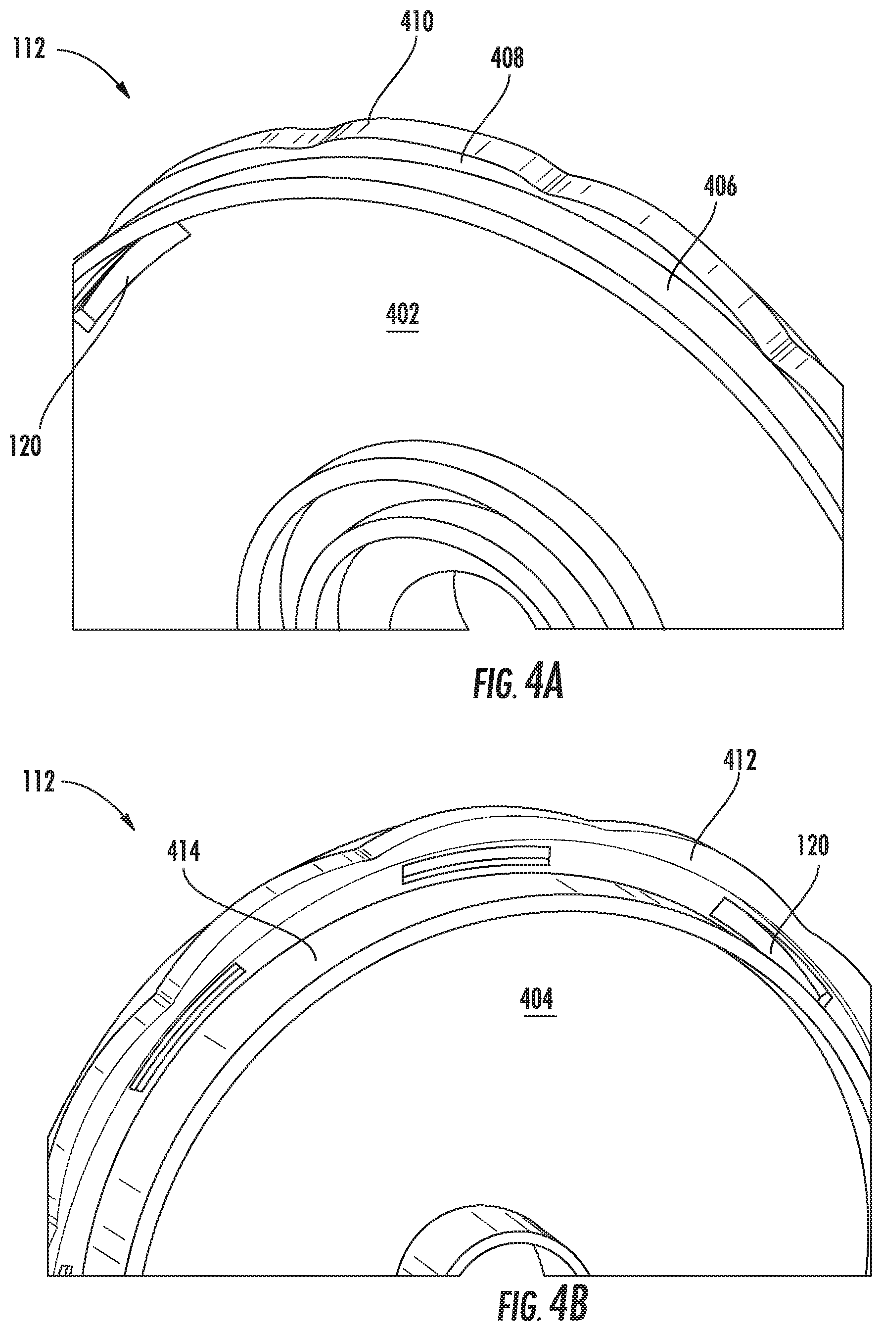
[0052] Referring to FIGS. 4A and 4B, views of the first endplate 112 are shown. FIG. 4A shows a portion of a perspective view of a top side of the first endplate 112. FIG. 4B shows a portion of a perspective view of a bottom side of the first endplate 112. The first endplate 112 includes a top surface 402 and a bottom surface 404. The top surface 402 and bottom surface 404 are parallel, or substantially parallel, and displaced from each other. The first endplate 112 includes a gasket retaining wall 406 extending from the top surface 402, a gasket retaining lip 408, an undulated wall 410, a housing support lip 412, and a lower wall 414 extending from the bottom surface. In some arrangements, the top surface 402, the gasket retaining lip 408, the housing support lip 412, and the bottom surface 404 are all parallel, or substantially parallel, to each other. In some arrangements, the gasket retaining wall 406, the undulated wall 410, and the lower wall 414 are perpendicular, or substantially perpendicular, to the top surface 402, the bottom surface 404, the gasket retaining lip 408, and/or the housing support lip 412. The gasket retaining wall 406 and the gasket retaining lip 408 define a second half of the U-shaped channel that receives the outer seal member 122 (as described above with respect to FIGS. 1 and 2). The undulated wall 410 and the housing support lip 412 are sized and shaped to be supported by the undulated wall 308 and the endplate retaining lip 310 of the shell housing 108 when the filter element 110 is installed in the shell housing 108. The undulated wall 410 defines an outer circumferential uneven surface such that is complimentary with undulated wall 308 of the shell housing 108. The undulated pattern that defines the undulated wall 308 may be continuous or intermittent throughout the inner circumference of the undulated wall 308. The undulated pattern may follow a wave pattern, a flower pattern, a triangular pattern, or the like so long as the undulated patter of the undulated wall 410 is complimentary with the undulated pattern of the undulated wall 308.
[0053] Accordingly, since the filter element 110 is an authorized filter element, the first endplate 112 can be received in the shell housing 108 as shown in FIGS. 5A and 5B. When the filter element 110 is installed in the shell housing 108, the undulated wall 410 of the first endplate 112 meshes with the undulated wall 308 of the shell housing 108 such that the first endplate 112 (and thus the filter element 110) cannot be rotated with respect to the shell housing 108. Further, as shown best in FIG. 2, when the filter element 110 is installed in the shell housing 108, the first endplate 112 and the shell housing 108 form a U-shaped channel that receives the outer seal member 122. The outer seal member 122 is supported by the gasket retaining wall 304, the gasket retaining lip 306, the gasket retaining wall 406, and the gasket retaining lip 408. When the filter element 110 is installed in the filtration system 100, the outer seal member 122 will undergo compression as it is pressed between the filter mounting head 102 and the U-shaped channel that causes the outer seal member 122 to press against the walls of the U-shaped channel and the filter mounting head 102. In some arrangements, the walls of the U-shaped channel are at least two-thirds the height of the outer seal member 122.
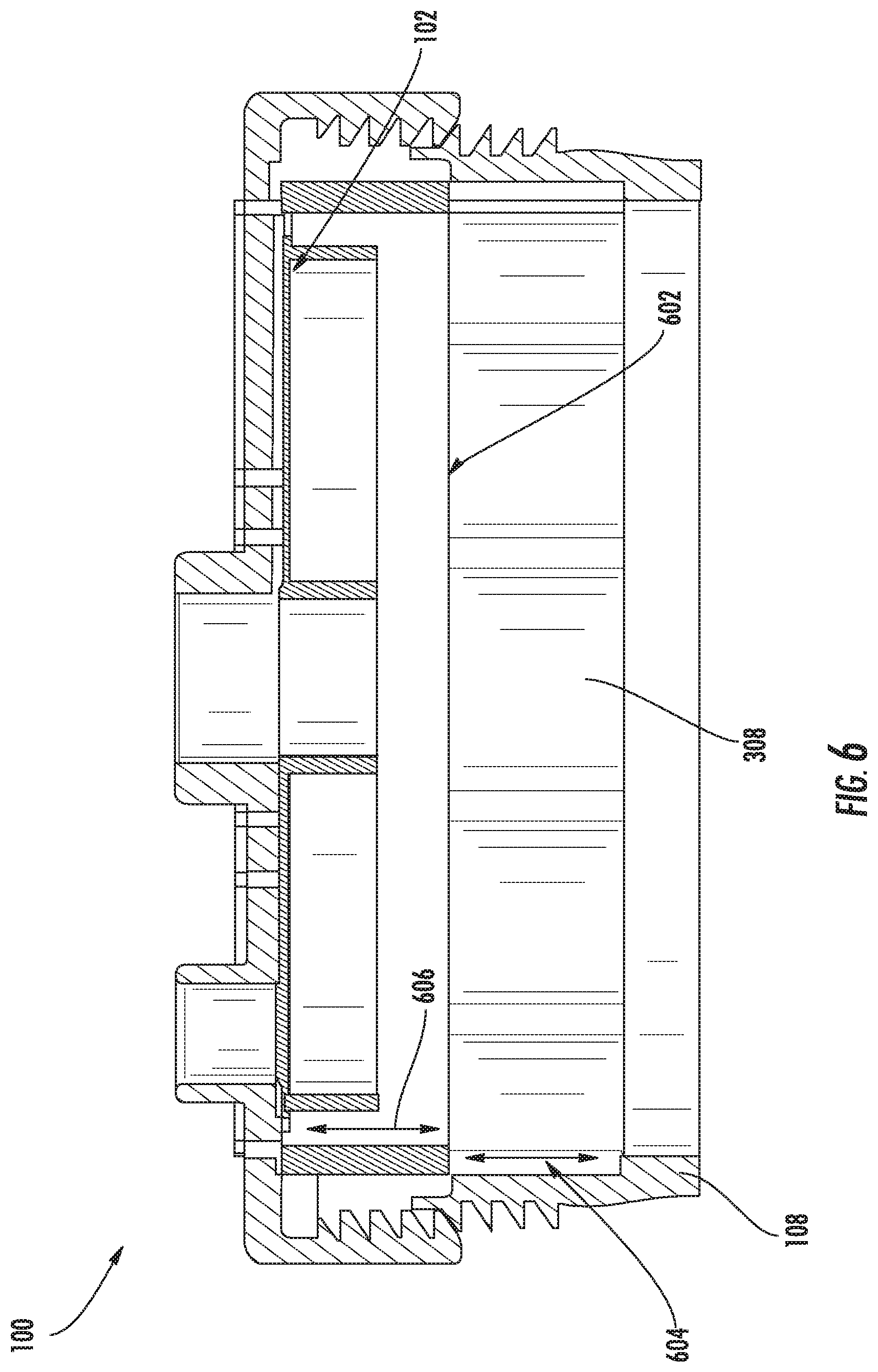
[0054] If a technician attempts to insert a non-authorized filter element into the shell housing 108 (e.g., a filter element that does not include a first endplate having the undulated wall 410), the non-authorized filter element will not fit in the shell housing 108. For example, as shown in FIG. 6, a first endplate 602 of a non-authorized filter element will not slide all the way in to the shell housing 108 because the pattern of the undulated wall 308 prevents the first endplate 602 from sliding into the shell housing 108. Accordingly, the non-authorized filter element is raised from a fully installed position by the height 604 of the undulated wall 308, and sits above the top of the undulated wall 308 by the height 606 of the first endplate. The height 604 is sufficiently large to allow the first endplate 602 to protrude above the top surface 302 of the shell housing 108. Since the first endplate 602 is raised, the first endplate 602 comes into contact with the filter mounting head 102 before the threaded connection between the shell housing 108 and the filter mounting head 102 is engaged (and before any seals form between the first endplate 602 and the filter mounting head 102), which prevents the non-authorized filter element from being installed in the filtration system 100. If a filter element is not installed in the filtration system 100, any corresponding system associated with the filtration system 100 (e.g., an internal combustion engine) may be prevented from starting. The height 604 may be varied depending on the application such that any installed non-authorized filter element protrudes above the top surface 302 thereby preventing the threads of the shell housing 108 from coupling to the threads of the filter mounting head 102.
[0055] Referring to FIGS. 7A, 7B, and 7C, a first endplate 702 and filter mounting head 704 are shown according to another example embodiment. The first endplate 707 and the filter mounting head 704 may be used in place of the first endplate 112 and the filter mounting head 102 in the same manner as described above with respect to the filtration system 100. Accordingly, like numbering is used to designate similar components between the filtration system 100 and the components shown in FIGS. 7A, 7B, and 7C. As shown in FIG. 7A, the first endplate 702 includes raised tabs 706 extending from the top surface 402. Although three tabs 706 are shown, any number of tabs may be positioned on the top surface 402. The tabs are evenly spaced at the same radius from a center point of the first endplate 702 such that the tabs fall along the circle 708 defined by the radius and the center point. As shown in FIG. 7B, the filter mounting head includes a circular channel 710. In some arrangements the circular channel 710 is interrupted with a notch 712 that interferes with the tabs 706 during rotation of the first endplate 702 with respect to the filter mounting head 704.
[0056] As shown best in FIG. 7C, the circular channel 710 is sized and shaped to receive the tabs 706 of the first endplate 702 when the filter element 110 is installed in the filtration system 100. During installation of the filter element 110 in the filtration system 100, the tabs 706 are received in the channel 710. As the shell housing 108 is rotated to form the threaded connection between the shell housing 108 and the filter mounting head 704, the filter element also rotates until one of the tabs 706 abuts the notch 712. The filter element 110 is then rotationally locked with respect to the filter mounting head 704 while the shell housing 108 continues to rotate. When the pattern of the undulated wall 410 lines up with the matching pattern of the undulated wall 308, the filter element 110 and the first endplate 702 drop into the shell housing 108 and will seat correctly within the shell housing 108 (e.g., as shown in FIG. 2). Accordingly, the tabs 706 and circular channel 710 having the notch 712 serve as a guiding feature that allows the filter element 110 to easily drop down into the shell housing 108 when the undulated patterns on the shell housing 108 and first endplate 702 line up. If a non-authorized filter element having a different tab arrangement (or no tabs) is attempted to be installed in the filtration system 100, the non-authorized filter element will not rotate and fall into the shell housing 108 as described above.
[0057] Referring to FIG. 8A, a perspective view of the outlines of a first endplate 802 and a second endplate 804 positioned within the shell housing 108 are shown according to an example embodiment. Each of the first endplate 802 or second endplate 804 may be substituted for the first endplate 112 of the filtration system 100. The first endplate 802 is inscribed within the undulating pattern that matches the undulated wall 308 of the shell housing 108 such that the first endplate 802 conforms to the small circle that can be drawn touching the troughs of the undulating pattern. The second endplate 804 circumscribes the undulating pattern of the undulated wall 308 of the shell housing 108 such that the second endplate 804 conforms to the largest circle that can be drawn touching the peaks of the undulating pattern. The first endplate 802 and second endplate 804 are described in further detail below with respect to FIGS. 8B through 8E.
[0058] FIG. 8B and 8C each show different views of the second endplate 804 positioned within the shell housing 108 as described above with respect to FIG. 8A. As shown in FIGS. 8B and 8C, the second endplate 804 is circumscribed with the undulating pattern that matches the undulated wall 308 of the shell housing 108 such that the second endplate 804 rests on the gasket retaining lip 306 of the shell housing 108. In this arrangement, the first endplate 802 only contacts the innermost edges of the undulating pattern of the undulated wall 308. In some arrangements, the second endplate 804 may form a seal with the shell housing 108.
[0059] FIG. 8D and 8E each show different views of the first endplate 802 positioned within the shell housing 108 as described above with respect to FIG. 8A. As shown in FIGS. 8D and 8E, the first endplate 802 is inscribed with the undulating pattern that matches the undulated wall 308 of the shell housing 108 such that the first endplate 802 rests on the gasket retaining lip 306 of the shell housing 108. In this arrangement, the first endplate 802 only contacts the innermost edges of the undulating pattern of the undulated wall 308. In some arrangements, the first endplate 802 may form a seal with the shell housing 108.
[0060] Referring to FIG. 9, a cross-sectional view of a filtration system 900 is shown according to an example embodiment. The filtration system 900 may be a fuel filtration system, a lubricant filtration system, a hydraulic fluid filtration system, a water filtration system, or the like. The filtration system 900 is similar to the filtration system 100 of FIG. 1. A difference between the filtration system 900 and the filtration system 100 is the integration of a nutplate on the first endplate of the filtration system 900. Similarly, the first endplate 912 may be used in place of the first endplate 112 in the same manner as described above with respect to the filtration system 100. Accordingly, like numbering is used to designate similar components between the filtration system 100 and the components shown in FIGS. 9, 10A, 10B, 11, 12A, 12B, and 13 of the filtration system 900. As shown in FIG. 9, the filtration system 900 includes a shell housing 908 and a filter element 910.
[0061] The shell housing 908 is substantially cylindrical in shape having an open top end adjacent to first endplate 912 and a closed bottom end opposite the open top end. The bottom end includes a protrusion to assist in removal of the shell housing 908 from the filter element 910 and/or filtration system 900. In some arrangements, the closed bottom end includes a closeable drain opening, a sensor port, or another opening that can be selectively sealed. The shell housing 908 includes a threaded member 906 formed around the top end of the shell housing 908. The threaded member 906 is configured to threadedly engage with a filter housing component (e.g., a filter mounting head) of the filtration system 900. In some embodiments, the shell housing 908 and the threaded member 906 are separate components.
[0062] A filter element 910 is installed in the filtration system 900. The filter element 910 is received in a central compartment formed by the shell housing 908. The filter element 910 includes a first endplate 912, a second endplate 914, and filter media 116 positioned between the first endplate 912 and the second endplate 914. The filter media 116 is arranged in a cylindrical manner between the first endplate 912 and the second endplate 914. The first endplate 912 includes a nutplate portion 1102 integrated with an endplate portion 1104 such that the top surface of the first endplate 912 is the nutplate portion 1102 and the bottom surface is an endplate portion 1104 vertically spaced away from the nutplate portion 1102 and structured to attach to the filter media 116. As will be appreciated, incorporating an integrated nutplate portion 1102 on an endplate portion 1104 to form the first endplate 912 of the filter element 910 reduces the need for additional components for interfacing with and sealing with the shell housing 908. As shown in FIG. 9, the first endplate 912 is an open endplate that includes a central opening 918 in fluid communication with an outlet. The second endplate 914 is a closed endplate. The first endplate 912 includes at least one inlet opening in fluid communication with an inlet. In some arrangements, one or both of the first endplate 912 and second endplate 914 may include raised tabs extending from a surface. The tabs may be evenly spaced at the same radius from a center point of the first endplate 912 and second endplate 914 such that the tabs fall along the circle defined by the radius and the center point.
[0063] The filtration system 900 includes an outer seal member 122 and an inner seal member 124. The outer seal member 122 is supported in a U-shaped channel formed by the first endplate 912 and the shell housing 908 (e.g., as shown in FIG. 9, which shows a cross-sectional view of the interaction between the first endplate 912 and the shell housing 908). The inner seal member 124 is supported in a U-shaped channel formed by projections on the first endplate 912. Specifically, the inner seal member 124 is supported by the inner gasket retaining walls 1216 and the inner gasket retaining lip 1124 of the first endplate 1412. When the filter element 910 and the shell housing 908 are installed in the filtration system 900 (e.g., as shown in FIG. 9), the outer seal member 122 and inner seal member are pressed against a cover or a filter head and form seals. In some embodiments, the shell housing 908 and the nutplate portion 1102 of the first endplate 912 interlock to form the outer seal member 122. In some arrangements, a space defined between the outer seal member 122 and the inner seal member 124 is in fluid communication with the inlet and the inlet openings. The space inside of the inner seal member 124 is in fluid communication with the outlet and the central opening 918. Accordingly, when the filter element 910 is installed in the filtration system (as shown in FIG. 9), fluid to be filtered flows through the inlet, through the inlet openings, through the filter media 116 in an outside-in flow direction, out the central opening 918, and out the outlet as shown by the flow arrows of FIG. 9.
[0064] As described in further detail below with respect to FIGS. 10A through 13, the shell housing 908 and the first endplate 912 include matching undulated surfaces that mesh when the filter element 910 is installed in the shell housing 908. Expanding generally, the nutplate portion 1102 of the first endplate 912 includes a top nutplate surface 1220 and a bottom nutplate surface 1222, with the undulated wall 1110 disposed between the top nutplate surface 1220 and a bottom nutplate surface 1222. The matching undulated surfaces include a plurality of curves or shapes. The matching undulated surfaces prevent the filter element 910 from rotating with respect to the shell housing 908 during installation of the shell housing 908 to the filter mounting head or other filter housing component. Additionally, the undulated surface of the shell housing 908 prevents a non-authorized filter element (e.g., a filter element without the matching undulated surface) from being installed in the shell housing 908 and ultimately installed in the filtration system 900.
[0065] Referring to FIGS. 10A and 10B, views of the shell housing 908 are shown. FIG. 10A shows a perspective view of the shell housing 908. FIG. 10B shows a cross-sectional view of the top portion of the shell housing 908 shown in FIG. 10A. As described above with respect to FIG. 9, the shell housing 908 includes an open top end. The open top end is defined by a top surface 1002, a gasket retaining wall 1004, a gasket retaining lip 1006, an undulated wall 1008, and an endplate retaining lip 1010. In some arrangements, the top surface 1002, the gasket retaining lip 1006, and the endplate retaining lip 1010 are parallel, or substantially parallel, surfaces. In some arrangements, the gasket retaining wall 1004 and the undulated wall 1008 are perpendicular, or substantially perpendicular, to the top surface 1002, the gasket retaining lip 1006, and/or the endplate retaining lip 1010. The gasket retaining wall 1004 and the gasket retaining lip 1006 define a first portion of the U-shaped channel (a first half of the U-shaped channel in one embodiment) that receives the outer seal member 122 (as described above with respect to FIG. 9).
[0066] The undulated wall 1008 and the endplate retaining lip 1010 receive the first endplate 912 when the filter element 910 is installed in the shell housing 908. The undulated wall 1008 defines an inner circumferential uneven surface such that only filter elements with a complimentary undulated wall (e.g., the undulated wall 1110 of the first endplate 912) can be retained in the shell housing 908. The undulated pattern that defines the undulated wall 1008 may be continuous or intermittent throughout the inner circumference of the undulated wall 1008. In some embodiments, and as shown in FIG. 10A, the undulated wall 1008 includes twelve replications of the undulated pattern (e.g., extrusion) extruded axially about the center of the shell housing 908 with a plurality of axial notches (e.g., curved extrusions) in-between each replication of the undulated pattern (although other numbers of replications could also be used). As used herein, "undulated" or "undulating" may refer to a repeating pattern or non-repeating pattern that may follow a wave pattern (e.g., a sinusoidal pattern), a flower pattern, a triangular pattern, or any other pattern such that a mating pattern can mesh with the undulated or undulating pattern.
[0067] FIG. 11 shows a perspective view of the filter element 910 of the filtration system 900 of FIG. 9. As described above with respect to FIG. 9, the filter element 910 includes a nutplate portion 1102 integrally formed on an endplate portion 1104 to form the first endplate 912. The nutplate portion 1102 and the endplate portion 1104 may be formed in a single injection shot. In some embodiments, the nutplate portion 1102 is a different color from the endplate portion 1104. The nutplate portion 1102 includes a plurality of ribs 1108, an outer gasket retaining lip 1122 (as shown in FIG. 12A), an outer gasket retaining wall 1206, an inner gasket retaining lip 1124 (as shown in FIG. 12A), inner gasket retaining walls 1216, and an undulated wall 1110. In some embodiments, the plurality of ribs 1108 assist in facilitating the installation of the filter element 910 into the shell housing 908. In some arrangements, the space defined between the plurality of ribs 1108 are inlet openings in fluid communication with an inlet, such that fluid to be filtered flows through the inlet, through the inlet openings, and into the filter media 116. The undulated wall 1110 includes an undulating or repeating pattern that mesh with the matching undulating or repeating pattern on the filter housing component (e.g., the undulated wall 1008 of the shell housing 908). The two undulating or repeating patterns "mesh" when the two patterns engage and lock in a similar manner as the teeth of two meshing gears thereby preventing substantial rotation of the first endplate 912 with respect to the shell housing 908 (i.e., preventing the endplate from rotating with respect to the filter housing component by more than five degrees in a given direction).
[0068] Referring to FIGS. 12A and 12B, views of the first endplate 912 are shown. FIG. 12A shows a cross-sectional view of the first endplate 912. FIG. 12B shows a perspective view of the first endplate 912. The first endplate 912 includes a top surface 1202 and a bottom surface 1204. The top surface 1202 and bottom surface 1204 are parallel, or substantially parallel, to and displaced from each other. The top surface 1202 includes the nutplate portion 1102 of the first endplate 912. The bottom surface 1204 includes the endplate portion 1104 of the first endplate 912. The nutplate portion 1102 of the first endplate 912 includes an outer gasket retaining wall 1206 extending from the top surface 1202, the outer gasket retaining lip 1122, inner gasket retaining walls 1216 extending from the top surface 1202, the inner gasket retaining lip 1124, an undulated wall 1110, and a housing support lip 1212. In some arrangements, the top surface 1202, the outer gasket retaining lip 1122, the inner gasket retaining lip 1124, the housing support lip 1212, and the bottom surface 1204 are all parallel, or substantially parallel, to each other. In some arrangements, the outer gasket retaining wall 1206, the inner gasket retaining walls 1216, and the undulated wall 1110 are perpendicular, or substantially perpendicular, to the top surface 1202, the bottom surface 1204, the gasket retaining lip 1208, and/or the housing support lip 1212. The outer gasket retaining wall 1206 and the outer gasket retaining lip 1122 define a second half of the U-shaped channel that receives the outer seal member 122 (as described above with respect to FIGS. 9 and 11).
[0069] The undulated wall 1110 and the housing support lip 1212 are sized and shaped to be supported by the undulated wall 1008 and the endplate retaining lip 1010 of the shell housing 908 when the filter element 910 is installed in the shell housing 908. The undulated wall 1110 defines an outer circumferential uneven surface such that is complimentary with undulated wall 1008 of the shell housing 908. The undulated pattern that defines the undulated wall 1008 may be continuous or intermittent throughout the inner circumference of the undulated wall 1008. The undulated pattern may follow a wave pattern, a flower pattern, a triangular pattern, or the like so long as the undulated patter of the undulated wall 1110 is complimentary with the undulated pattern of the undulated wall 1008. In some embodiments, and as shown in FIG. 12B, the undulated wall 1110 includes twelve replications of the undulated pattern (e.g., extrusion) extruded axially about the center of the nutplate portion 1102 of the first endplate 912 that are complementary to twelve replications of the undulated pattern extruded axially about the center of the shell housing 908 on the undulated wall 1008 (with other numbers of replications being used if other replications are used for the undulated pattern extruded axially about the center of the shell housing 908 on the undulated wall 1008).
[0070] The endplate portion 1104 includes a top endplate surface 1230 that is parallel, or substantially parallel, to and displaced from a bottom endplate surface 1232. The endplate portion 1104 includes an axially protruding flange 1234 extending away from the bottom endplate surface 1232 toward the second endplate 914. As will be appreciated, the top surface 1202, the bottom surface 1204, the top nutplate surface 1220, the bottom nutplate surface 1222, the top endplate surface 1230, and the bottom endplate surface 1232 are parallel, or substantially parallel, to each other. Additionally, the top surface 1202 of the first endplate 912 is a circumferential protrusion extending away from and around the top nutplate surface 1220. As shown in FIG. 12A, the top nutplate surface 1220 is displaced axially away from the bottom nutplate surface 1222 by a greater distance than the axial distance between the top endplate surface 1230 and the bottom endplate surface 1232. A space 1224 is formed between the bottom nutplate surface 1222 and the top endplate surface 1230. The nutplate portion 1102 and the endplate portion 1104 are integrated such that the fluid flows through the top surface 1202 of the first endplate 912, through the openings between the plurality of ribs 1108 on the top nutplate surface 1220, into the space 1224, and around the top endplate surface 1230 and the flange 1234 to contact the filter media 116. In some embodiments, the space 1224 is configured to control inlet fuel flow through the first endplate 912 towards the filter media 116.
[0071] Accordingly, since the filter element 910 is an authorized filter element, the first endplate 912 can be received in the shell housing 908 as shown in the filtration system 900 of FIG. 13. When the filter element 910 is installed in the shell housing 908, the undulated wall 1110 of the first endplate 912 meshes with the undulated wall 1008 of the shell housing 908 such that the first endplate 912 (and thus the filter element 910) cannot be rotated with respect to the shell housing 908. Further, when the filter element 910 is installed in the shell housing 908, the first endplate 912 and the shell housing 908 form a U-shaped channel that receives the outer seal member 122. The outer seal member 122 is supported by the outer gasket retaining wall 1206, the outer gasket retaining lip 1122, the gasket retaining wall 1004, and the gasket retaining lip 1006. When the filter element 910 is installed in the filtration system 100, the outer seal member 122 will undergo compression as it is pressed between a filter housing component (e.g., filter mounting head) and the U-shaped channel that causes the outer seal member 122 to press against the walls of the U-shaped channel and the filter housing component. In some arrangements, the walls of the U-shaped channel are at least two-thirds the height of the outer seal member 122.
[0072] If a technician attempts to insert a non-authorized filter element into the shell housing 908 (e.g., a filter element that does not include a first endplate having the undulated wall 1110), the non-authorized filter element will not fit in the shell housing 908. For example, a first endplate of a non-authorized filter element will not slide all the way in to the shell housing 908 because the pattern of the undulated wall 1008 prevents the unauthorized first endplate from sliding into the shell housing 908. Accordingly, the non-authorized filter element is raised from a fully installed position by the height of the undulated wall 1008, and sits above the top of the undulated wall 1008 by the height of the unauthorized first endplate. The height is sufficiently large to allow the unauthorized first endplate to protrude above the top surface 1002 of the shell housing 908. Since the unauthorized first endplate is raised, the unauthorized first endplate comes into contact with a filter mounting head before the threaded connection between the shell housing 108 and the filter mounting head is engaged (and before any seals form between the unauthorized first endplate and the filter mounting head), which prevents the unauthorized filter element from being installed in the filtration system 900. If a filter element is not installed in the filtration system 900, any corresponding system associated with the filtration system 900 (e.g., an internal combustion engine) may be prevented from starting.
[0073] Turning to FIG. 14, a cross-sectional view of a filtration system 1400 is shown according to an example embodiment. The filtration system 1400 may be a fuel filtration system, a lubricant filtration system, a hydraulic fluid filtration system, a water filtration system, or the like. The filtration system 1400 is similar to the filtration system 100 of FIG. 1. A difference between the filtration system 1400 and the filtration system 100, is repeating pattern of the filter housing that meshes with a complementary pattern on an endplate of the filter element. Specifically, the pattern on the endplate includes mesh protrusions (e.g., snap fingers) that interlock (e.g., snap) with a lip formed on the inside of the filter housing. Similarly, the first endplate 1412 may be used in place of the first endplate 112 in the same manner as described above with respect to the filtration system 100. In some embodiments, the filtration system 1400 may include fingers spaced radially along the outside of the endplate (or a nutplate) to interlock with a shell housing that includes a corresponding set of slots that the fingers might interlock with. Accordingly, like numbering is used to designate similar components between the filtration system 100 and the components shown in FIGS. 14, 15A, 15B, and 16. As shown in FIG. 14, the filtration system 1400 includes a shell housing 1408 and a filter element 910.
[0074] The shell housing 1408 is substantially cylindrical in shape having an open top end adjacent to first endplate 912 and a closed bottom end opposite the open top end. The bottom end includes a biasing member (e.g., spring) 1420 between the bottom end and a location to receive the filter element 1410. The biasing member 1420 is structured to facilitate the "snap-in" installation of the filter element 1410 into the shell housing 1408 and applies a biasing force of the filter element 1410 to ensure engagement of the filter element protruding wall with a complementary surface of the shell housing 1408. In some arrangements, the closed bottom end includes a closeable drain opening, a sensor port, or another opening that can be selectively sealed. The shell housing 1408 is structured to engage a threaded member 1406 (e.g., collar) formed around the top end of the shell housing 1408. The threaded member 1406 is configured to snap fit onto the shell housing 1408 and threadedly engage with a filter housing component (e.g., a filter mounting head) of the filtration system 1400. In some embodiments, the shell housing 1408 and the threaded member 1406 are formed as one component. Beneficially, the threaded member 1406 and shell housing 1408 are locked together to impede vertical movement and rotation between the threaded member 1406 and the shell housing 1408.
[0075] A filter element 1410 is installed in the filtration system 1400. The filter element 1410 is received in a central compartment formed by the shell housing 1408. The filter element 1410 includes a first endplate 1412, a second endplate 1414, and filter media 116 positioned between the first endplate 1412 and the second endplate 1414. The filter media 116 is arranged in a cylindrical manner between the first endplate 1412 and the second endplate 1414. As shown in FIG. 14, the first endplate 1412 is an open endplate that includes a central opening 1418 in fluid communication with an outlet. The second endplate 1414 is a closed endplate. The first endplate 1412 includes at least one inlet opening in fluid communication with an inlet. In some arrangements, one or both of the first endplate 1412 and second endplate 1414 may include raised tabs extending from a surface. The tabs may be evenly spaced at the same radius from a center point of the first endplate 1412 and second endplate 1414 such that the tabs fall along the circle defined by the radius and the center point.
[0076] The filtration system 1400 includes an outer seal member 122 and an inner seal member 124. The outer seal member 122 is supported in a U-shaped channel formed in the shell housing 1408 (e.g., as shown in FIG. 14, which shows a cross-sectional view of the channel around the outside of the shell housing 1408). The inner seal member 124 is supported in a U-shaped channel formed by projections on the first endplate 1412. Specifically, the inner seal member 124 is supported by the inner gasket retaining walls 1616 and the inner gasket retaining lip 1624 of the first endplate 1412. When the filter element 1410 and the shell housing 1408 are installed in the filtration system 1400 (e.g., as shown in FIG. 14), outer seal member 122 and inner seal member are pressed against a cover or a filter head and form seals. In some arrangements, a space defined between the outer seal member 122 and the inner seal member 124 is in fluid communication with the inlet and the inlet openings. The space inside of the inner seal member 124 is in fluid communication with the outlet and the central opening 1418. Accordingly, when the filter element 1410 is installed in the filtration system (as shown in FIG. 14), fluid to be filtered flows through the inlet, through the inlet openings, through the filter media 116 in an outside-in flow direction, out the central opening 1418, and out the outlet as shown by the flow arrows of FIG. 14.
[0077] As described in further detail below with respect to FIGS. 15A, 15B, and 16, the shell housing 1408 and the first endplate 1412 include complementary (e.g., matching) surfaces that mesh when the filter element 1410 is installed in the shell housing 1408. The matching surfaces include at least one radially protruding wall around an outside surface of the first endplate 1412. The matching surfaces facilitate a snap fit of the filter element 1410 with respect to the shell housing 1408 during installation of the shell housing 1408 to the filter mounting head or other filter housing component. Once installed, the matching surfaces impede the vertical movement of the filter element 1410 inside the shell housing 1408. Additionally, the surface of the shell housing 1408 prevents a non-authorized filter element (e.g., a filter element without the matching undulated surface) from being installed in the shell housing 1408 and ultimately installed in the filtration system 1400.
[0078] Referring to FIGS. 15A and 15B, views of the shell housing 1408 are shown. FIG. 15A shows a perspective view of the shell housing 1408. FIG. 15B shows a cross-sectional view of the top portion of the shell housing 1408 shown in FIG. 15A. As described above with respect to FIG. 14, the shell housing 1408 includes an open top end. The open top end is defined by a top surface 1502, a first gasket retaining wall 1504, a gasket retaining lip 1522, a second gasket retaining wall 1506, a recessed (e.g., patterned) wall 1508, a recessed lip 1512, and an endplate retaining lip 1510. In some arrangements, the first gasket retaining wall 1504, the second gasket retaining wall 1506, and the wall 1508 are perpendicular, or substantially perpendicular, to the top surface 1502, the second gasket retaining wall 1506, and/or the endplate retaining lip 1510. Contrary to the shell housing 108 or shell housing 908, a U-shaped channel that receives the outer seal member 122 (as described above with respect to FIG. 14) is formed directly in the shell housing 1408. Specifically, the outer seal member 122 is received by a channel formed by the first gasket retaining wall 1504, the second gasket retaining wall 1506, and the gasket retaining lip 1522. The recessed wall 1508 and the endplate retaining lip 1510 receive the first endplate 1412 when the filter element 1410 is installed in the shell housing 1408. The recessed wall 1508 defines an inner circumferential recessed surface such that only filter elements with complimentary protrusions (e.g., the protruding wall 1610 of the first endplate 1412) can be retained in the shell housing 1408. The recessed pattern that defines the recessed wall 1508 may be continuous or intermittent throughout the inner circumference of the recessed wall 1508. As used herein, "recessed" may refer to a repeating pattern or non-repeating pattern that may follow a continuous pattern, a wave pattern (e.g., a sinusoidal pattern), a flower pattern, a triangular pattern, or any other pattern such that a mating pattern can mesh with the protrusion. As will be appreciated, the endplate retaining lip 1510 facilitates the protruding wall 1610 of the first endplate 1412 engaging the recessed wall 1508.
[0079] FIG. 16 shows a perspective view of the filter element 1410 of the filtration system 1400 of FIG. 14. As described above with respect to FIG. 14, the filter element 1410 includes a first endplate 1412 with at least one radially protruding wall 1610. The first endplate 1412 includes a top surface 1602 and a bottom surface 1604. The top surface 1062 and bottom surface 1604 are parallel, or substantially parallel, and displaced from each other. The first endplate 1412 includes the inner gasket retaining walls 1616 extending from the top surface 1602, an inner gasket retaining lip 1624, and, extending downward from the top surface 1602, an axially protruding flange 1614 with a radially protruding wall 1610 along the surface of the protruding flange 1614. In some embodiments, the axially protruding flange 1614 is flexible in the radial direction toward the filter media 116. In some arrangements, the top surface 1602, the inner gasket retaining lip 1624 and the bottom surface 1604 are all parallel, or substantially parallel, to each other. In some arrangements, the inner gasket retaining walls 1616 and the axially protruding flange 1614 are perpendicular, or substantially perpendicular, to the top surface 1602, the bottom surface 1604, and the inner gasket retaining lip 1624. In some arrangements, the axially protruding flange 1614 is continuous around a circumference of the filter element 1410. In some arrangements, the radially protruding wall 1610 is continuous around a circumference of the filter element 1410. The radially protruding wall 1610 includes a shape (e.g., triangular, rectangular, obtuse, angled, etc.) that allows for the first endplate 1412 to be vertically pressed down, past the recessed lip 1512 and endplate retaining lip 1510 thereby causing the axially protruding flange 1614 to flex inward. In some embodiments, the radially protruding wall 1610 is substantially parallel to the top surface 1602, the inner gasket retaining lip 1624 and the bottom surface 1604.
[0080] Accordingly, since the filter element 1410 is an authorized filter element, the first endplate 1412 can be received in the shell housing 1408. When the filter element 1410 is installed in the shell housing 1408, the radially protruding wall 1610 of the first endplate 1412 drops into the shell housing 1408. Once the radially protruding wall 1610 is pushed below the endplate retaining lip 1510, the mesh of the shape of the radially protruding wall 1610 and the shape of the endplate retaining lip 1510 of the shell housing 1408 impedes vertical movement of the filter element 1410 with respect to the shell housing 1408. As will be appreciated, the biasing member 1420 is structured to facilitate the "snap-in" installation of the filter element 1410 into the shell housing 1408 and applies a vertical force of the filter element 1410 to ensure engagement of the radially protruding wall 1610 of the first endplate 1412 with the complementary surface of the shell housing 1408. In other words, the two repeating patterns "mesh" when the two patterns engage and lock in a similar manner as the teeth of two meshing gears thereby preventing substantial rotation of the first endplate 1412 with respect to the shell housing 1408.
[0081] As shown in FIG. 16, the radially protruding wall 1610 further includes a housing support lip 1612 that is complementary to the endplate retaining lip 1510 of the shell housing 1408 such that the engagement of the housing support lip 1612 and the endplate retaining lip 1510 impedes vertical movement of the filter element 1410 with respect to the shell housing 1408. Further, when the filter element 1410 is installed in the shell housing 1408, the outer gasket channel (e.g., the channel formed by the first gasket retaining wall 1504, the second gasket retaining wall 1506, and the gasket retaining lip 1522) receives the outer seal member 122. When the filter element 1410 is installed in the filtration system 1400, the outer seal member 122 will undergo compression as it is pressed between a filter housing component (e.g., filter mounting head) and the U-shaped channel that causes the outer seal member 122 to press against the walls of the U-shaped channel and the filter housing component. In some arrangements, the walls of the U-shaped channel are at least two-thirds the height of the outer seal member 122.
[0082] If a technician attempts to insert a non-authorized filter element into the shell housing 1408 (e.g., a filter element that does not include a first endplate having the radially protruding wall 1610), the non-authorized filter element will not fit in the shell housing 1408. For example, a first endplate of a non-authorized filter element will not slide all the way in to the shell housing 1408 because the pattern of the recessed wall 1508 prevents the unauthorized first endplate from sliding into the shell housing 1408. Accordingly, the non-authorized filter element is raised from a fully installed position by the height of the recessed wall 1508, and sits above the top of the recessed wall 1508 by the height of the unauthorized first endplate. The height is sufficiently large to allow the unauthorized first endplate to protrude above the top surface 1502 of the shell housing 1408. Since the unauthorized first endplate is raised, the unauthorized first endplate comes into contact with a filter mounting head before the threaded connection between the shell housing 108 and the filter mounting head is engaged (and before any seals form between the unauthorized first endplate and the filter mounting head), which prevents the unauthorized filter element from being installed in the filtration system 1400. If a filter element is not installed in the filtration system 1400, any corresponding system associated with the filtration system 1400 (e.g., an internal combustion engine) may be prevented from starting.
[0083] Referring to FIG. 17, a cross-sectional view of a filtration system 1700 is shown according to another example embodiment. The filtration system 1700 may be a fuel filtration system, a lubricant filtration system, a hydraulic fluid filtration system, a water filtration system, or the like. The filtration system 1700 is similar to the filtration system 900 of FIG. 9 in many respects. A difference between the filtration system 1700 and the filtration system 900 is a modification of the undulated wall of the nutplate where the nutplate interlocks with the housing. The filtration system 1700 includes a different pattern and numerosity of replicated patters extruded axially about the center of the first endplate 1712 and shell housing 1708 compared to the filtration system 900. In some embodiments, the filtration system 1700 includes six replications of the pattern extruded axially about the center of the filtration system 1700 on the undulated walls of the shell housing 1708 and first endplate 1712, as opposed to twelve replications of the pattern extruded axially about the center of the filtration system 900 on the undulated walls of the shell housing 908 and first endplate 912. As will be appreciated, the differing undulated patterns prevents the first endplate 912 to be used in place of the first endplate 1712 with the shell housing 1708 of the filtration system 1700. Relatedly, the differing undulated patterns prevents the first endplate 1712 to be used in place of the first endplate 912 with the shell housing 908 of the filtration system 900. Accordingly, like numbering is used to designate similar components between the filtration system 900 and the components shown in FIGS. 17, 18A, 18B, 19, 20A, 20B, and 21 of the filtration system 1700. As shown in FIG. 17, the filtration system 1700 includes a shell housing 1708 and a filter element 1710.
[0084] The shell housing 1708 is substantially cylindrical in shape, having an open top end adjacent to first endplate 1712 and a closed bottom end opposite the open top end. The bottom end includes a protrusion to assist in removal of the shell housing 1708 from the filter element 1710 and/or filtration system 1700. In some arrangements, the closed bottom end includes a closeable drain opening, a sensor port, or another opening that can be selectively sealed. The shell housing 1708 includes a threaded member 1706 formed around the top end of the shell housing 1708. The threaded member 1706 is configured to engage with the threads of a filter housing component (e.g., a filter mounting head) of the filtration system 1700. In some embodiments, the shell housing 1708 and the threaded member 1706 are separate components.
[0085] A filter element 1710 is installed in the filtration system 1700. The filter element 1710 is received in a central compartment formed by the shell housing 1708. The filter element 1710 includes a first endplate 1712, a second endplate 1714, and filter media 116 positioned between the first endplate 1712 and the second endplate 1714. The filter media 116 is arranged in a cylindrical manner between the first endplate 1712 and the second endplate 1714. The first endplate 1712 includes a nutplate portion 1902 integrated with an endplate portion 1904 such that the top surface of the first endplate 1712 is the nutplate portion 1902 and the bottom surface is an endplate portion 1904 vertically spaced away from the nutplate portion 1902 and structured to attach to the filter media 116. As will be appreciated, incorporating an integrated nutplate portion 1902 on an endplate portion 1904 to form the first endplate 1712 of the filter element 1710 reduces the need for additional components for interfacing with and sealing with the shell housing 1708. As shown in FIG. 17, the first endplate 1712 is an open endplate that includes a central opening 1718 in fluid communication with an outlet. The second endplate 1714 is a closed endplate. The first endplate 1712 includes at least one inlet opening in fluid communication with an inlet. In some arrangements, one or both of the first endplate 1712 and second endplate 1714 may include raised tabs extending from a surface. The tabs may be evenly spaced at the same radius from a center point of the first endplate 1712 and second endplate 1714 such that the tabs fall along the circle defined by the radius and the center point.
[0086] The filtration system 1700 includes an outer seal member 122 and an inner seal member 124. The outer seal member 122 is supported in a U-shaped channel formed by the first endplate 1712 and the shell housing 1708 (e.g., as shown in FIG. 17, which shows a cross-sectional view of the interaction between the first endplate 1712 and the shell housing 1708). The inner seal member 124 is supported in a U-shaped channel formed by projections on the first endplate 1712. Specifically, the inner seal member 124 is supported by the inner gasket retaining walls 2016 and the inner gasket retaining lip 1924 of the first endplate 1712. When the filter element 1710 and the shell housing 1708 are installed in the filtration system 1700 (e.g., as shown in FIG. 17), the outer seal member 122 and inner seal member are pressed against a cover or a filter head and form seals. In some embodiments, the shell housing 1708 and the nutplate portion 1902 of the first endplate 1712 interlock to form the outer seal member 122. In some arrangements, a space defined between the outer seal member 122 and the inner seal member 124 is in fluid communication with the inlet and the inlet openings. The space inside of the inner seal member 124 is in fluid communication with the outlet and the central opening 1718. Accordingly, when the filter element 1710 is installed in the filtration system (as shown in FIG. 17), fluid to be filtered flows through the inlet, through the inlet openings, through the filter media 116 in an outside-in flow direction, out the central opening 918, and out the outlet as shown by the flow arrows of FIG. 17.
[0087] As described in further detail below with respect to FIGS. 18A through 21, the shell housing 1708 and the first endplate 1712 include matching undulated surfaces that mesh when the filter element 1710 is installed in the shell housing 1708. Expanding generally, the nutplate portion 1902 of the first endplate 1712 includes a top nutplate surface 2020 and a bottom nutplate surface 2029, with the undulated wall 1910 disposed between the top nutplate surface 2020 and a bottom nutplate surface 2029. The matching undulated surfaces include a plurality of curves or shapes. The matching undulated surfaces prevent the filter element 1710 from rotating with respect to the shell housing 1708 during installation of the shell housing 1708 to the filter mounting head or other filter housing component. Additionally, the undulated surface of the shell housing 1708 prevents a non-authorized filter element (e.g., a filter element without the matching undulated surface) from being installed in the shell housing 1708 and ultimately installed in the filtration system 1700.
[0088] Referring to FIGS. 18A and 18B, views of the shell housing 1708 are shown. FIG. 18A shows a perspective view of the shell housing 1708. FIG. 18B shows a cross-sectional view of the top portion of the shell housing 1708 shown in FIG. 18A. As described above with respect to FIG. 17, the shell housing 1708 includes an open top end. The open top end is defined by a top surface 1802, a gasket retaining wall 1804, a gasket retaining lip 1806, an undulated wall 1808, and an endplate retaining lip 1810. In some arrangements, the top surface 1802, the gasket retaining lip 1806, and the endplate retaining lip 1810 are parallel, or substantially parallel, surfaces. In some arrangements, the gasket retaining wall 1804 and the undulated wall 1808 are perpendicular, or substantially perpendicular, to the top surface 1802, the gasket retaining lip 1806, and/or the endplate retaining lip 1810. The gasket retaining wall 1804 and the gasket retaining lip 1806 define a first portion of the U-shaped channel (a first half of the U-shaped channel in one embodiment) that receives the outer seal member 122 (as described above with respect to FIG. 17).
[0089] The undulated wall 1808 and the endplate retaining lip 1810 receive the first endplate 1712 when the filter element 1710 is installed in the shell housing 1708. The undulated wall 1808 defines an inner circumferential uneven surface such that only filter elements with a complimentary undulated wall (e.g., the undulated wall 1910 of the first endplate 1712) can be retained in the shell housing 1708. The undulated pattern that defines the undulated wall 1808 may be continuous or intermittent throughout the inner circumference of the undulated wall 1808. In some embodiments, and as shown in FIG. 18A, the undulated wall 1808 includes six replications of the undulated pattern (e.g., extrusion) extruded axially about the center of the shell housing 1708. As used herein, "undulated" or "undulating" may refer to a repeating pattern or non-repeating pattern that may follow a wave pattern (e.g., a sinusoidal pattern), a flower pattern, a triangular pattern, or any other pattern such that a mating pattern can mesh with the undulated or undulating pattern.
[0090] FIG. 19 shows a perspective view of the filter element 1710 of the filtration system 1700 of FIG. 17. As described above with respect to FIG. 17, the filter element 1710 includes a nutplate portion 1902 integrally formed on an endplate portion 1904 to form the first endplate 1712. The nutplate portion 1902 and the endplate portion 1904 may be formed in a single injection shot. In some embodiments, the nutplate portion 1902 is a different color from the endplate portion 1904. The nutplate portion 1902 includes a plurality of ribs 1908, an outer gasket retaining lip 1922 (as shown in FIG. 20A), an outer gasket retaining wall 2006, an inner gasket retaining lip 1924 (as shown in FIG. 20A), inner gasket retaining walls 2016, and an undulated wall 1910. In some embodiments, the plurality of ribs 1908 assist in facilitating the installation of the filter element 1710 into the shell housing 1708. In some arrangements, the space defined between the plurality of ribs 1908 are inlet openings in fluid communication with an inlet, such that fluid to be filtered flows through the inlet, through the inlet openings, and into the filter media 116. The undulated wall 1910 includes an undulating or repeating pattern that mesh with the matching undulating or repeating pattern on the filter housing component (e.g., the undulated wall 1808 of the shell housing 1708). The two undulating or repeating patterns "mesh" when the two patterns engage and lock in a similar manner as the teeth of two meshing gears thereby preventing substantial rotation of the first endplate 1712 with respect to the shell housing 1708 (i.e., preventing the endplate from rotating with respect to the filter housing component by more than five degrees in a given direction).
[0091] Referring to FIGS. 20A and 20B, views of the first endplate 1712 are shown. FIG. 12A shows a cross-sectional view of the first endplate 1712. FIG. 20B shows a perspective view of the first endplate 1712. The first endplate 1712 includes a top surface 2002 and a bottom surface 2004. The top surface 2002 and bottom surface 2004 are parallel, or substantially parallel, to and displaced from each other. The top surface 2002 includes the nutplate portion 1902 of the first endplate 1712. The bottom surface 2004 includes the endplate portion 1904 of the first endplate 1712. The nutplate portion 1902 of the first endplate 1712 includes an outer gasket retaining wall 2006 extending from the top surface 2002, the outer gasket retaining lip 1922, inner gasket retaining walls 2016 extending from the top surface 2002, the inner gasket retaining lip 1924, an undulated wall 1910, and a housing support lip 2012. In some arrangements, the top surface 2002, the outer gasket retaining lip 1922, the inner gasket retaining lip 1924, the housing support lip 2012, and the bottom surface 2004 are all parallel, or substantially parallel, to each other. In some arrangements, the outer gasket retaining wall 2006, the inner gasket retaining walls 2016, and the undulated wall 1910 are perpendicular, or substantially perpendicular, to the top surface 2002, the bottom surface 2004, the gasket retaining lip 2008, and/or the housing support lip 2012. The outer gasket retaining wall 2006 and the outer gasket retaining lip 1922 define a second half of the U-shaped channel that receives the outer seal member 122 (as described above with respect to FIGS. 17 and 19).
[0092] The undulated wall 1910 and the housing support lip 2012 are sized and shaped to be supported by the undulated wall 1808 and the endplate retaining lip 1810 of the shell housing 1708 when the filter element 1710 is installed in the shell housing 1708. The undulated wall 1910 defines an outer circumferential uneven surface such that is complimentary with undulated wall 1808 of the shell housing 1708. The undulated pattern that defines the undulated wall 1808 may be continuous or intermittent throughout the inner circumference of the undulated wall 1808. The undulated pattern may follow a wave pattern, a flower pattern, a triangular pattern, or the like so long as the undulated patter of the undulated wall 1910 is complimentary with the undulated pattern of the undulated wall 1808. In some embodiments, and as shown in FIG. 20B, the undulated wall 1910 includes six replications of the undulated pattern (e.g., extrusion) extruded axially about the center of the nutplate portion 1902 of the first endplate 1712 that are complementary to six replications of the undulated pattern extruded axially about the center of the shell housing 1708 on the undulated wall 1008.
[0093] The endplate portion 1904 includes a top endplate surface 2030 that is parallel, or substantially parallel, to and displaced from a bottom endplate surface 2032. The endplate portion 1904 includes an axially protruding flange 2034 extending away from the bottom endplate surface 2032 toward the second endplate 1714. As will be appreciated, the top surface 2002, the bottom surface 2004, the top nutplate surface 2020, the bottom nutplate surface 2029, the top endplate surface 2030, and the bottom endplate surface 2032 are parallel, or substantially parallel, to each other. Additionally, the top surface 2002 of the first endplate 1712 is a circumferential protrusion extending away from and around the top nutplate surface 2020. As shown in FIG. 20A, the top nutplate surface 2020 is displaced axially away from the bottom nutplate surface 2029 by a greater distance than the axial distance between the top endplate surface 2030 and the bottom endplate surface 2032. A space 2024 is formed between the bottom nutplate surface 2029 and the top endplate surface 2030. The nutplate portion 1902 and the endplate portion 1904 are integrated such that the fluid flows through the top surface 2002 of the first endplate 1712, through the openings between the plurality of ribs 1908 on the top nutplate surface 2020, into the space 2024, and around the top endplate surface 1230 and the flange 1234 to contact the filter media 116. In some embodiments, the space 2024 is configured to control inlet fuel flow through the first endplate 1712 towards the filter media 116.
[0094] Accordingly, since the filter element 1710 is an authorized filter element, the first endplate 1712 can be received in the shell housing 1708 as shown in the filtration system 1700 of FIG. 21. When the filter element 1710 is installed in the shell housing 1708, the undulated wall 1910 of the first endplate 1712 meshes with the undulated wall 1808 of the shell housing 1708 such that the first endplate 1712 (and thus the filter element 1710) cannot be rotated with respect to the shell housing 1708. Further, when the filter element 1710 is installed in the shell housing 1708, the first endplate 1712 and the shell housing 1708 form a U-shaped channel that receives the outer seal member 122. The outer seal member 122 is supported by the outer gasket retaining wall 2006, the outer gasket retaining lip 1922, the gasket retaining wall 1804, and the gasket retaining lip 1806. When the filter element 1710 is installed in the filtration system 1700, the outer seal member 122 will undergo compression as it is pressed between a filter housing component (e.g., filter mounting head) and the U-shaped channel that causes the outer seal member 122 to press against the walls of the U-shaped channel and the filter housing component. In some arrangements, the walls of the U-shaped channel are at least two-thirds the height of the outer seal member 122.
[0095] If a technician attempts to insert a non-authorized filter element into the shell housing 1708 (e.g., a filter element that does not include a first endplate having the undulated wall 1910), the non-authorized filter element will not fit in the shell housing 1708. For example, a first endplate of a non-authorized filter element will not slide all the way in to the shell housing 1708 because the pattern of the undulated wall 1808 prevents the unauthorized first endplate from sliding into the shell housing 1708. Accordingly, the non-authorized filter element is raised from a fully installed position by the height of the undulated wall 1808, and sits above the top of the undulated wall 1808 by the height of the unauthorized first endplate. The height is sufficiently large to allow the unauthorized first endplate to protrude above the top surface 1802 of the shell housing 1708. Since the unauthorized first endplate is raised, the unauthorized first endplate comes into contact with a filter mounting head before the threaded connection between the shell housing 908 and the filter mounting head is engaged (and before any seals form between the unauthorized first endplate and the filter mounting head), which prevents the unauthorized filter element from being installed in the filtration system 1700. If a filter element is not installed in the filtration system 1700, any corresponding system associated with the filtration system 1700 (e.g., an internal combustion engine) may be prevented from starting.
[0096] The above described undulating pattern of any of the above described arrangements (e.g., of the undulated walls 308, 410, 1008, 1110, 1508, 1610, 1808, and 1910), can be varied from product to product to designate different characteristics of given filtration systems of filter elements. The difference characteristics may include any combination of media type, filter element service life, application (e.g., on vs. off highway), filter type (e.g., fuel, oil, water, etc.), presence of special components (e.g., coalescing layers, screens, etc.), filter media grade, filter element efficiency or ISO code, filter element stage designation, the presence of sensors, or the like. The undulating pattern can be changed by varying the shape of the pattern (e.g., rounded flower petals, jagged teeth, geometric shapes, etc.), the frequency of the pattern (e.g., the number of petals, teeth, etc.), the color of the endplate, the material of the endplate, the size of the entry holes, the number of entry holes, the depth of the pattern, or a combination thereof.
[0097] It should be noted that any use of the term "example" herein to describe various embodiments is intended to indicate that such embodiments are possible examples, representations, and/or illustrations of possible embodiments (and such term is not intended to connote that such embodiments are necessarily extraordinary or superlative examples).
[0098] The terms "coupled" and the like as used herein mean the joining of two members directly or indirectly to one another. Such joining may be stationary (e.g., permanent) or moveable (e.g., removable or releasable). Such joining may be achieved with the two members or the two members and any additional intermediate members being integrally formed as a single unitary body with one another or with the two members or the two members and any additional intermediate members being attached to one another.
[0099] References herein to the positions of elements (e.g., "top," "bottom," "above," "below," etc.) are merely used to describe the orientation of various elements in the FIGURES. It should be noted that the orientation of various elements may differ according to other example embodiments, and that such variations are intended to be encompassed by the present disclosure.
[0100] It is important to note that the construction and arrangement of the various example embodiments are illustrative only. Although only a few embodiments have been described in detail in this disclosure, those skilled in the art who review this disclosure will readily appreciate that many modifications are possible (e.g., variations in sizes, dimensions, structures, shapes and proportions of the various elements, values of parameters, mounting arrangements, use of materials, colors, orientations, etc.) without materially departing from the novel teachings and advantages of the subject matter described herein. For example, elements shown as integrally formed may be constructed of multiple parts or elements, the position of elements may be reversed or otherwise varied, and the nature or number of discrete elements or positions may be altered or varied. The order or sequence of any process or method steps may be varied or re-sequenced according to alternative embodiments. Additionally, features from particular embodiments may be combined with features from other embodiments as would be understood by one of ordinary skill in the art. Other substitutions, modifications, changes and omissions may also be made in the design, operating conditions and arrangement of the various example embodiments without departing from the scope of the present invention.
* * * * *
D00000
D00001
D00002
D00003
D00004
D00005
D00006
D00007
D00008
D00009
D00010
D00011
D00012
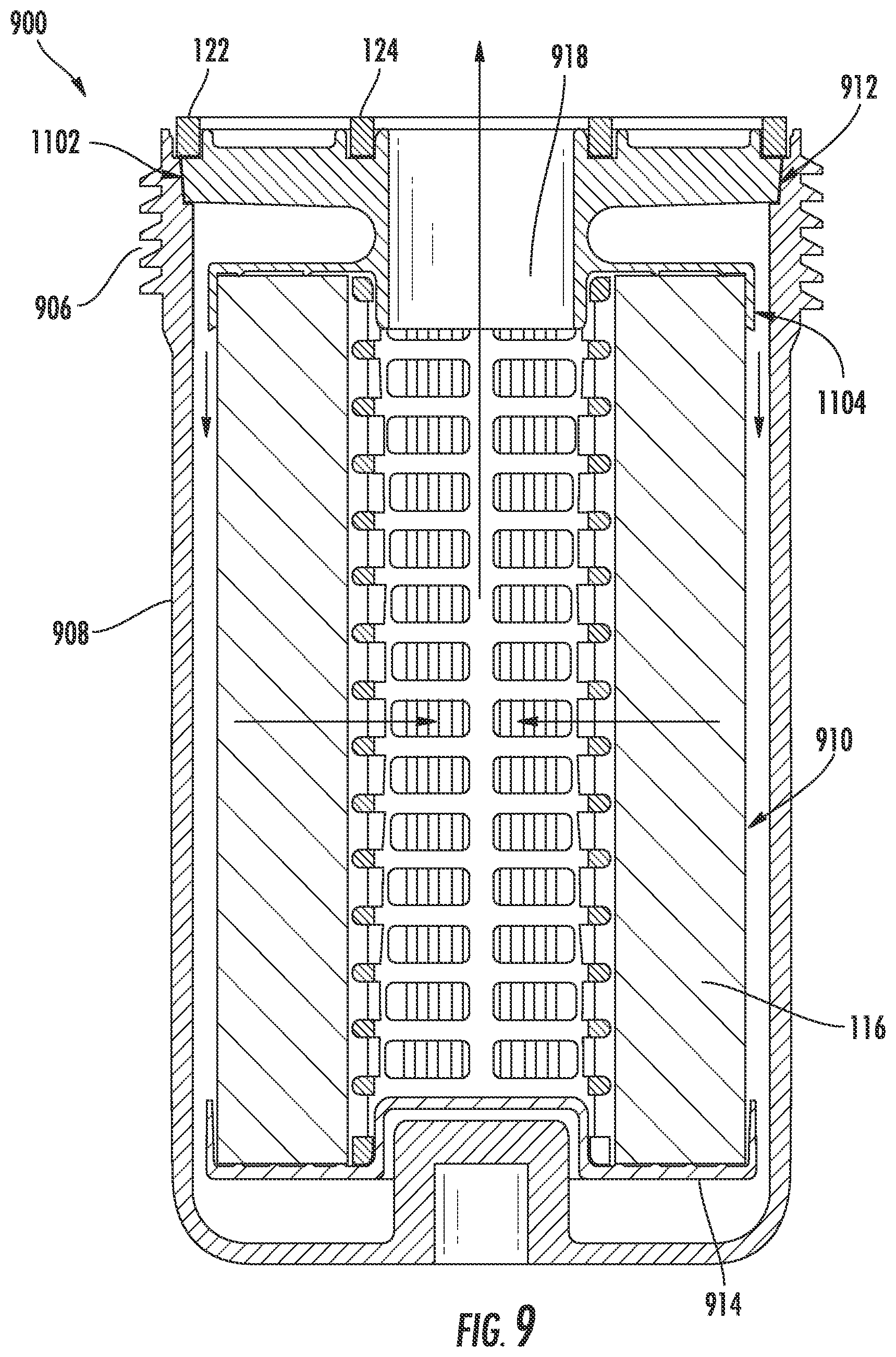
D00013
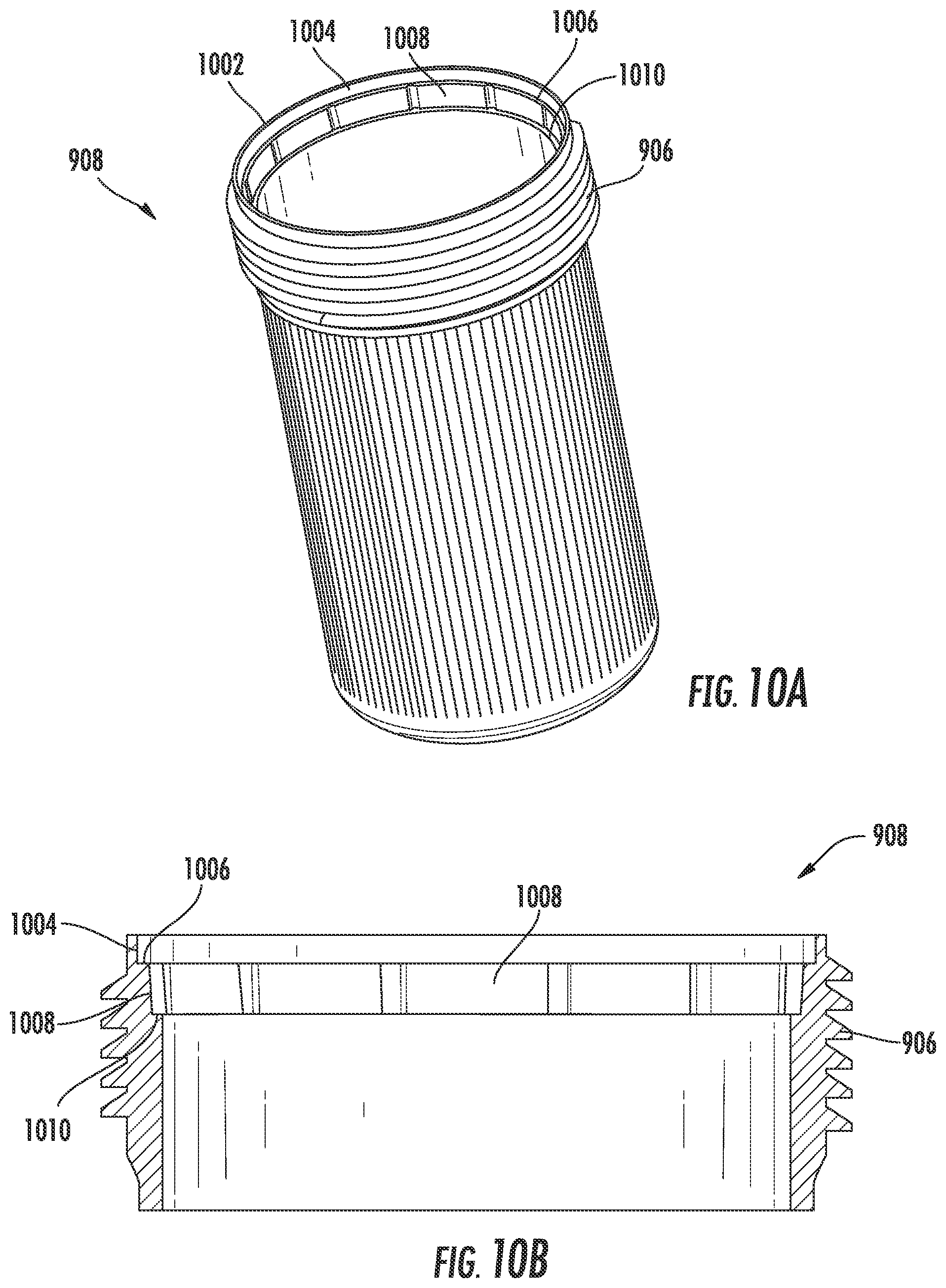
D00014
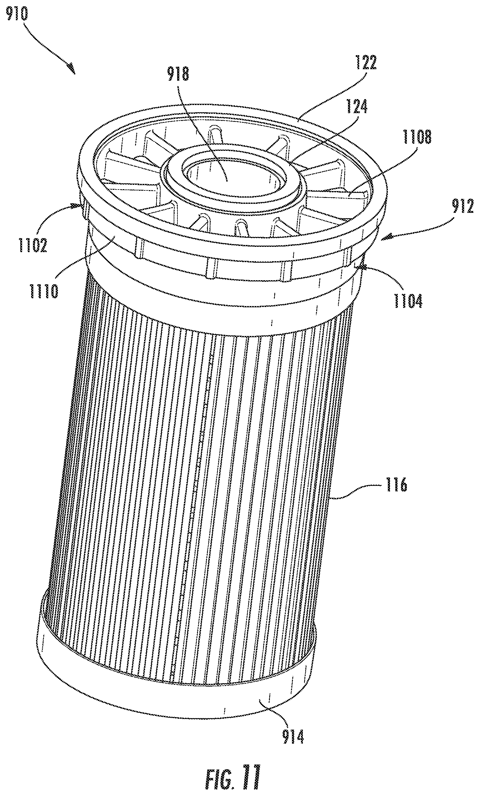
D00015

D00016

D00017
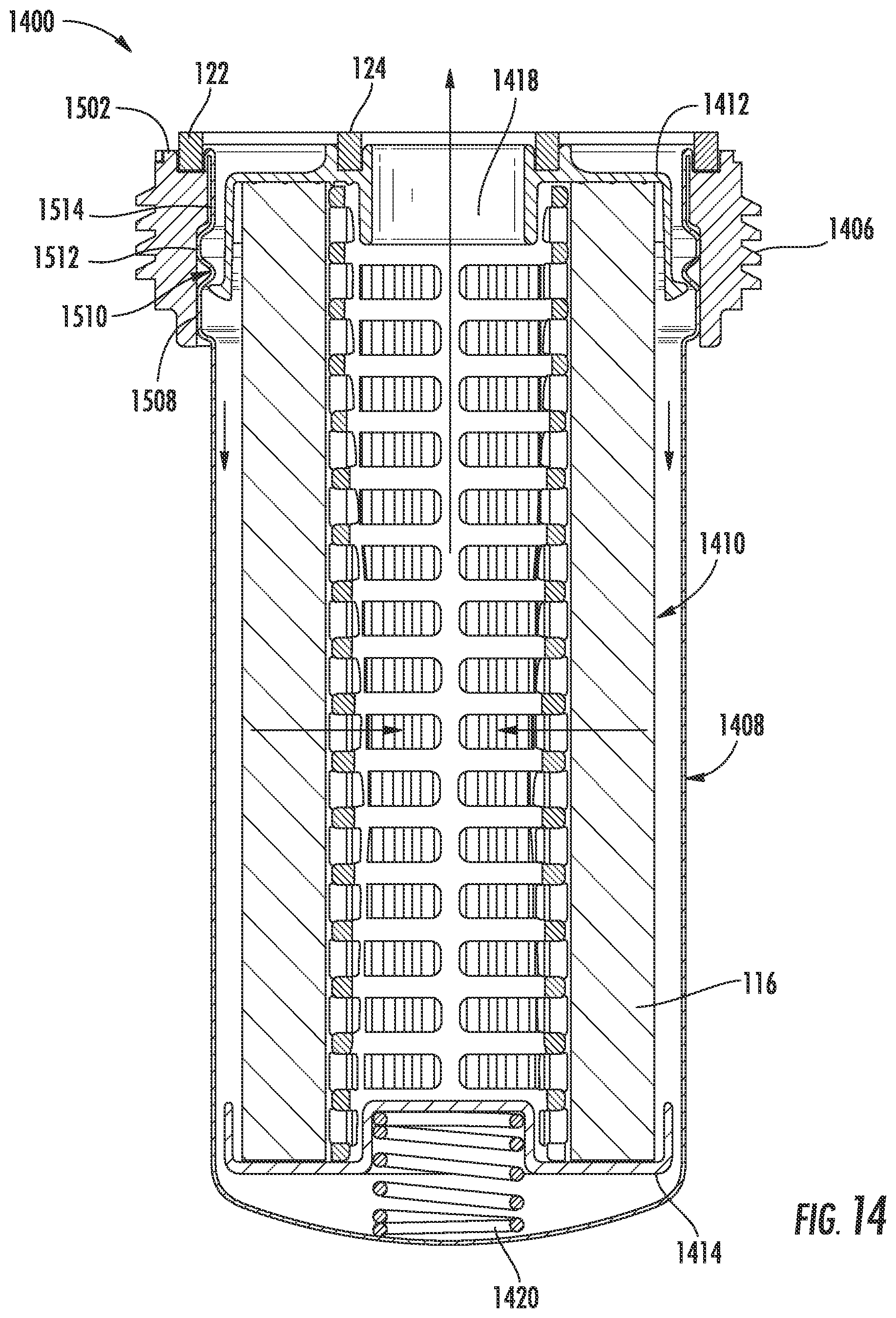
D00018
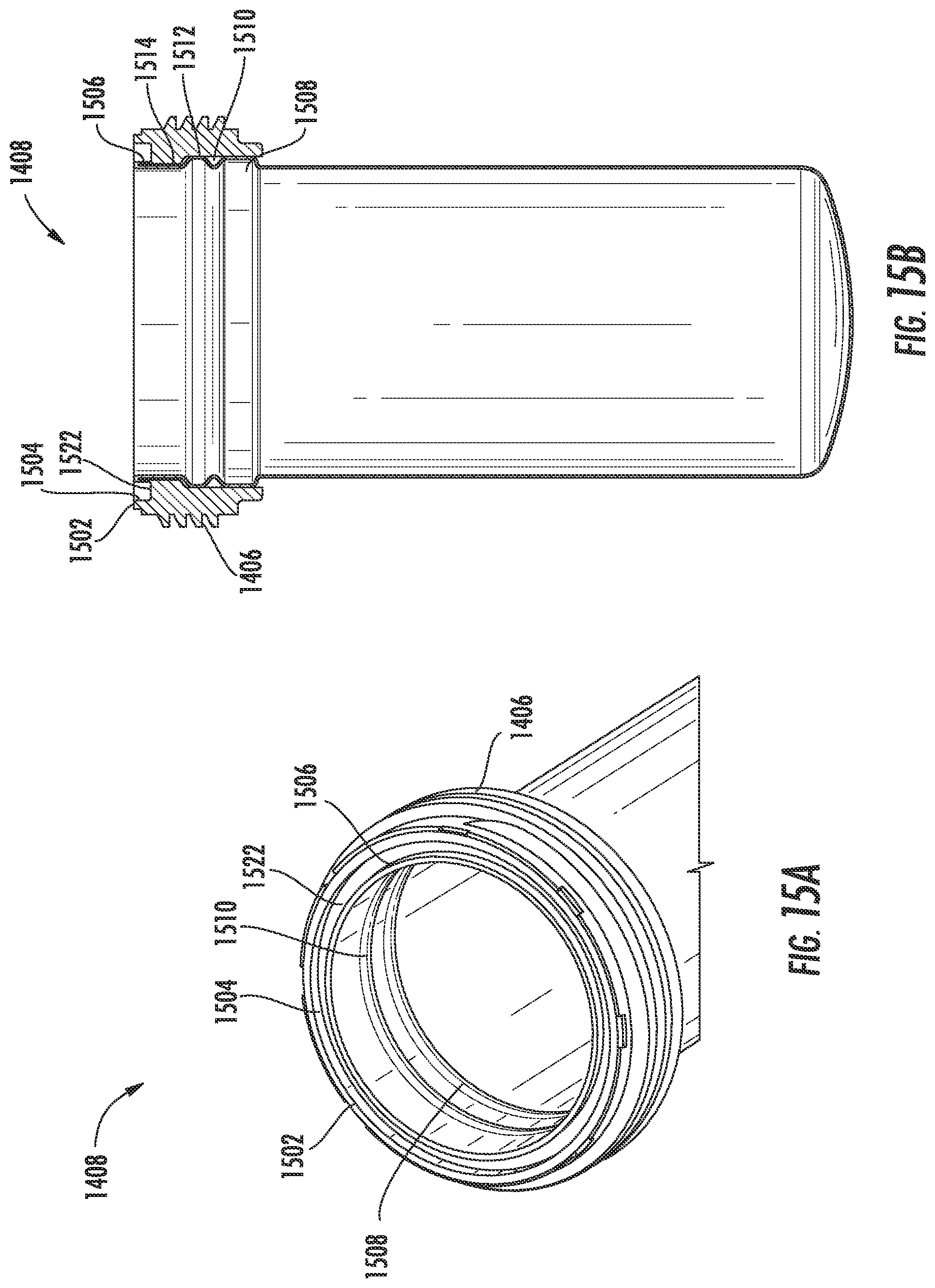
D00019

D00020

D00021
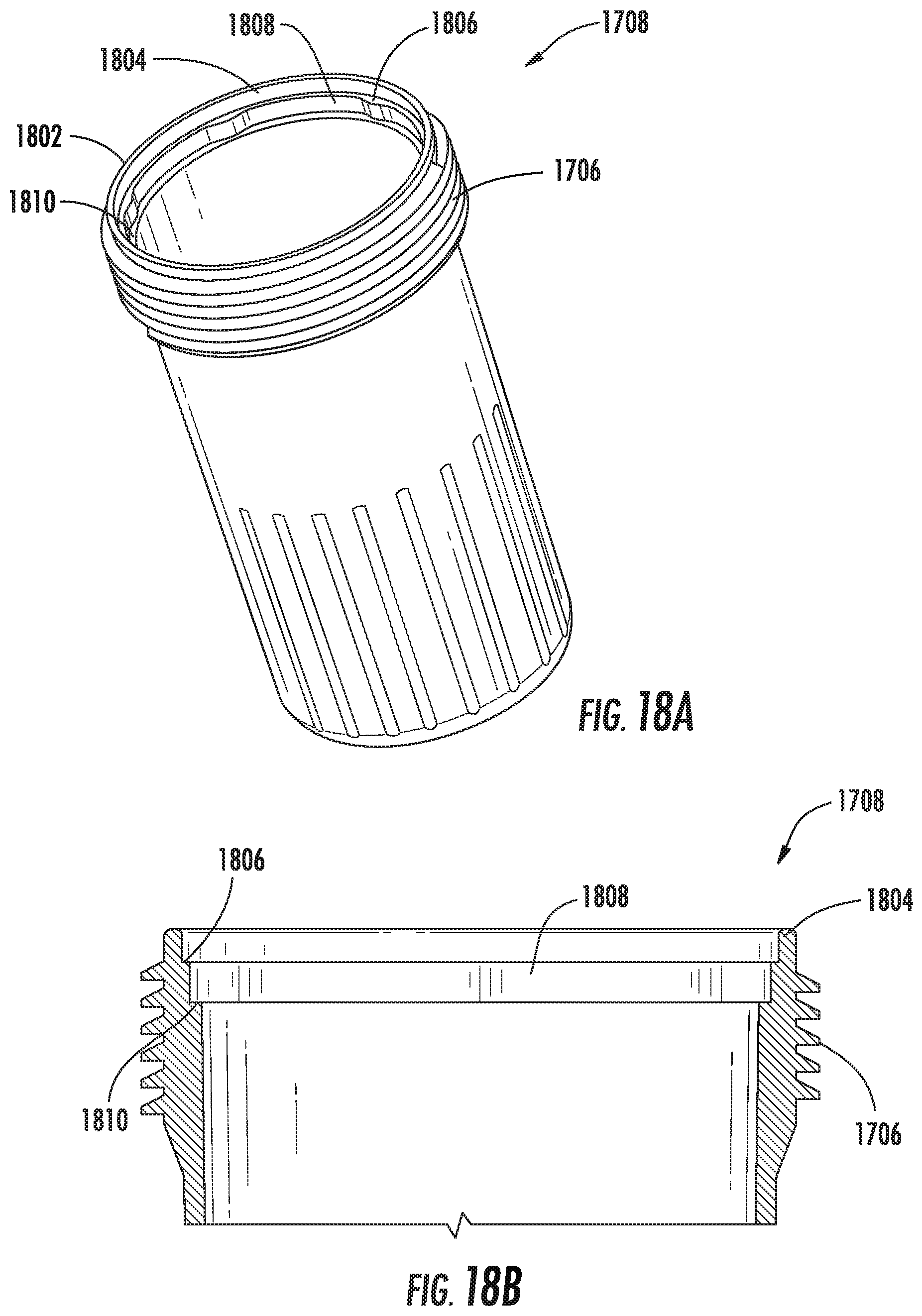
D00022

D00023

D00024
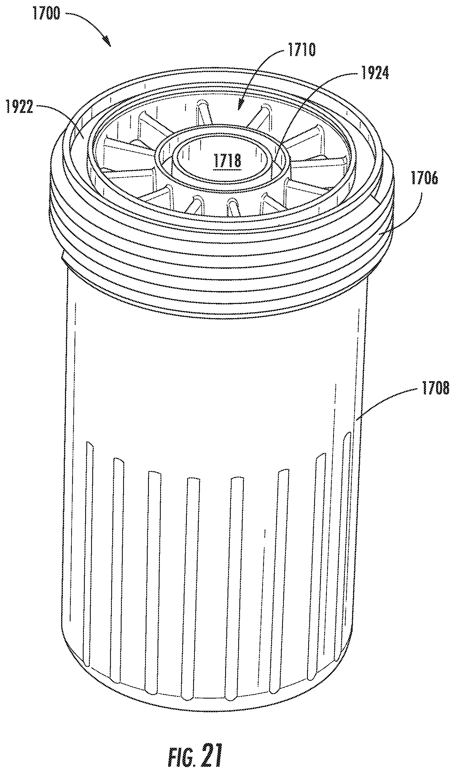
XML
uspto.report is an independent third-party trademark research tool that is not affiliated, endorsed, or sponsored by the United States Patent and Trademark Office (USPTO) or any other governmental organization. The information provided by uspto.report is based on publicly available data at the time of writing and is intended for informational purposes only.
While we strive to provide accurate and up-to-date information, we do not guarantee the accuracy, completeness, reliability, or suitability of the information displayed on this site. The use of this site is at your own risk. Any reliance you place on such information is therefore strictly at your own risk.
All official trademark data, including owner information, should be verified by visiting the official USPTO website at www.uspto.gov. This site is not intended to replace professional legal advice and should not be used as a substitute for consulting with a legal professional who is knowledgeable about trademark law.