Applicator Cap With Interconnect Feature
Park; Kyoo Jin
U.S. patent application number 16/431611 was filed with the patent office on 2020-12-10 for applicator cap with interconnect feature. This patent application is currently assigned to L'Oreal. The applicant listed for this patent is L'Oreal. Invention is credited to Kyoo Jin Park.
| Application Number | 20200383457 16/431611 |
| Document ID | / |
| Family ID | 1000004127940 |
| Filed Date | 2020-12-10 |


| United States Patent Application | 20200383457 |
| Kind Code | A1 |
| Park; Kyoo Jin | December 10, 2020 |
APPLICATOR CAP WITH INTERCONNECT FEATURE
Abstract
A cosmetic formula applicator configured for use with a handle for improved ergonomics and to aid in application by a user. In general, examples of the applicators described herein include a cap for coupling the applicator to a bottle. The cap includes a cavity configured to receive a corresponding protrusion of the handle therein. The cap includes a retainer associated with the cavity to interface with the protrusion to create a releasable connection requiring a larger separation force to release than without the retainer. The applicator may include a data storage device configured to communicate information to a sensor positioned in the handle.
| Inventors: | Park; Kyoo Jin; (Clark, NJ) | ||||||||||
| Applicant: |
|
||||||||||
|---|---|---|---|---|---|---|---|---|---|---|---|
| Assignee: | L'Oreal Paris FR |
||||||||||
| Family ID: | 1000004127940 | ||||||||||
| Appl. No.: | 16/431611 | ||||||||||
| Filed: | June 4, 2019 |
| Current U.S. Class: | 1/1 |
| Current CPC Class: | A46B 2200/1046 20130101; A46B 9/021 20130101; A45D 40/265 20130101; A46B 5/021 20130101 |
| International Class: | A45D 40/26 20060101 A45D040/26; A46B 9/02 20060101 A46B009/02; A46B 5/02 20060101 A46B005/02 |
Claims
1. An applicator for applying a cosmetic formula, the applicator comprising: a first end of the applicator configured to retain an amount of the cosmetic formula for application; a cap positioned at a second end of the applicator opposite the first end, the cap having a coupling portion configured to releasably couple the applicator to a bottle of cosmetic formula, and a cavity extending at least partially into the cap and configured to receive a corresponding protrusion therein; and a retainer associated with the cavity, the retainer configured to interface with the protrusion to create a releasable connection requiring a larger separation force to release than without the retainer.
2. The applicator of claim 1, wherein the retainer includes a magnet positioned adjacent to the cavity, the magnet configured to magnetically interface with a magnet positioned in the protrusion for creating the releasable connection.
3. The applicator of claim 1, wherein the retainer is selected from the group consisting of a magnet, threads, press fit, snap fit, clearance fit, and combinations thereof, the retainer configured to cooperatingly interface with the protrusion for creating the releasable connection.
4. The applicator of claim 1, wherein the application end has a plurality of application bristles configured to retain an amount of the cosmetic formula for application.
5. The applicator of claim 1, wherein the cavity has a non-circular cross section configured to fix the applicator from rotating about a central axis of the elongate stem with respect to the protrusion when the applicator is releasably connected to the protrusion.
6. The applicator of claim 1, wherein the cap includes a data storage device configured to communicate information to a sensor positioned in the protrusion.
7. The applicator of claim 1, further comprising an elongate stem positioned between the application end and the cap.
8. An applicator for applying a cosmetic formula using an articulating handle, the applicator comprising: an elongate stem having an application end configured to retain an amount of the cosmetic formula for application; a cap positioned at an end of the elongate stem opposite the application end; a cavity extending at least partially into the cap and configured to receive a corresponding protrusion of the articulating handle therein; and a retainer associated with the cavity, the retainer configured to interface with the protrusion to create a releasable connection requiring a larger separation force to release than without the retainer.
9. The applicator of claim 8, wherein the retainer includes a magnet positioned adjacent to the cavity, the magnet configured to magnetically interface with a magnet positioned in the protrusion for creating the releasable connection.
10. The applicator of claim 8, wherein the retainer is selected from the group consisting of a magnet, threads, press fit, snap fit, clearance fit, and combinations thereof, the retainer configured to cooperatingly interface with the protrusion for creating the releasable connection.
11. The applicator of claim 8, wherein the application end has a plurality of application bristles configured to retain an amount of the cosmetic formula for application.
12. The applicator of claim 8, wherein the cavity has a non-circular cross section configured to fix the applicator from rotating about a central axis of the elongate stem with respect to the protrusion when the applicator is releasably connected to the protrusion.
13. The applicator of claim 8, wherein the cap includes a data storage device configured to communicate information to a sensor positioned in the articulating handle.
14. The applicator of claim 8, wherein the articulating handle is configured to orient the applicator between 45.degree. and 90.degree. with respect to an axis of the articulating handle during application to eyelashes.
15. The applicator of claim 8, wherein the articulating handle is configured to orient the applicator substantially horizontal with respect to the ground during application to eyelashes.
16. The applicator of claim 8, wherein the articulating handle is configured to orient the applicator between 30.degree. and 80.degree. with respect to an axis of the articulating handle during application to lips.
17. The applicator of claim 8, wherein the articulating handle is configured to orient the applicator between 45.degree. and 60.degree. from horizontal with respect to the ground during application to lips.
18. The applicator of claim 8, wherein the articulating handle is configured to orient the applicator between about 0.degree. and 60.degree. with respect to an axis of the articulating handle during application to nails.
19. The applicator of claim 8, wherein the articulating handle is configured to orient the applicator at about 45.degree. from horizontal with respect to the ground during application to nails.
20. The applicator of claim 8, wherein the articulating handle is configured to orient the applicator between about 0.degree. and 90.degree. with respect to an axis of the articulating handle during application to a face.
Description
SUMMARY
[0001] The present disclosure is directed to, among other things, representative embodiments of an applicator for cosmetic formula having an interconnect feature. In an embodiment, the applicator includes an elongate stem having an application end configured to retain an amount of the cosmetic formula for application. In some embodiments, the applicator further includes a cap positioned at an end of the elongate stem opposite the application end such that the applicator can releasably couple to a bottle of cosmetic formula. In one embodiment, the cap has a cavity extending at least partially into the cap and configured to receive a corresponding protrusion therein, for example, a protrusion of an ergonomic handle. The cap further includes a retainer associated with the cavity configured to interface with the protrusion to create a releasable connection requiring a larger separation force to release than without the retainer.
[0002] The present disclosure is also directed to one or more embodiments of a cosmetic formula applicator configured for use with an articulating handle. In an embodiment, the applicator includes an elongate stem having an application end configured to retain an amount of the cosmetic formula for application. In some embodiments, the applicator further includes a cap positioned at an end of the elongate stem opposite the application end, and a cavity extending at least partially into the cap and configured to receive a corresponding protrusion of the articulating handle therein. In embodiments, the cap further includes a retainer associated with the cavity and configured to interface with the protrusion to create a releasable connection requiring a larger separation force to release than without the retainer.
[0003] In accordance with any of the embodiments described herein, the retainer may include a magnet positioned adjacent to the cavity, the magnet configured to magnetically interface with a magnet positioned in the protrusion for creating the releasable connection.
[0004] In accordance with any of the embodiments described herein, the retainer may be selected from the group consisting of a magnet, threads, press fit, snap fit, clearance fit, and combinations thereof, the retainer configured to cooperatingly interface with the protrusion for creating the releasable connection.
[0005] In accordance with any of the embodiments described herein, the application end may have a plurality of application bristles configured to retain an amount of the cosmetic formula for application.
[0006] In accordance with any of the embodiments described herein, the cavity may have a non-circular cross section configured to fix the applicator from rotating about a central axis of the elongate stem with respect to the protrusion when the applicator is releasably connected to the protrusion.
[0007] In accordance with any of the embodiments described herein, the cap may include a data storage device configured to communicate information to a sensor positioned in the protrusion.
[0008] In accordance with any of the embodiments described herein, the articulating handle may be configured to orient the applicator between 45.degree. and 90.degree. with respect to an axis of the articulating handle during application to eyelashes.
[0009] In accordance with any of the embodiments described herein, the articulating handle may be configured to orient the applicator substantially horizontal with respect to the ground during application to eyelashes.
[0010] In accordance with any of the embodiments described herein, the articulating handle may be configured to orient the applicator between 30.degree. and 80.degree. with respect to an axis of the articulating handle during application to lips.
[0011] In accordance with any of the embodiments described herein, the articulating handle may be configured to orient the applicator between 45.degree. and 60.degree. from horizontal with respect to the ground during application to lips.
[0012] In accordance with any of the embodiments described herein, the articulating handle may be configured to orient the applicator between about 0.degree. and 60.degree. with respect to an axis of the articulating handle during application to nails.
[0013] In accordance with any of the embodiments described herein, the articulating handle may be configured to orient the applicator at about 45.degree. from horizontal with respect to the ground during application to nails.
[0014] In accordance with any of the embodiments described herein, the articulating handle may be configured to orient the applicator between about 0.degree. and 90.degree. with respect to an axis of the articulating handle during application to a face.
[0015] This summary is provided to introduce a selection of concepts in a simplified form that are further described below in the Detailed Description. This summary is not intended to identify key features of the claimed subject matter, nor is it intended to be used as an aid in determining the scope of the claimed subject matter.
DESCRIPTION OF THE DRAWINGS
[0016] The foregoing aspects and many of the attendant advantages of the disclosed subject matter will become more readily appreciated as the same become better understood by reference to the following detailed description, when taken in conjunction with the accompanying drawings, wherein:
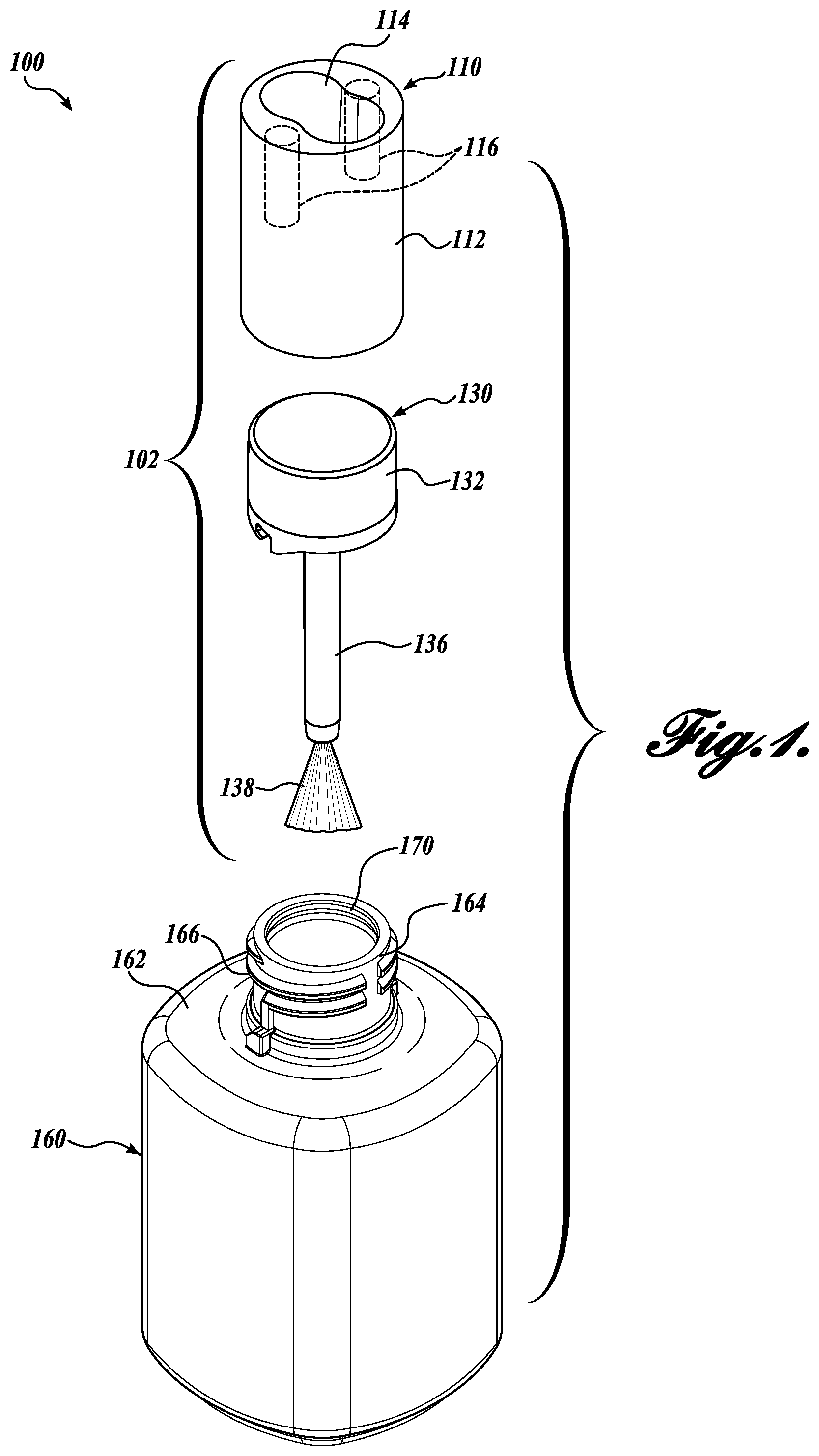
[0017] FIG. 1 is an exploded view of one representative embodiment of a cosmetic formula container having an applicator cap with an interconnect feature in accordance with an aspect of the present disclosure;
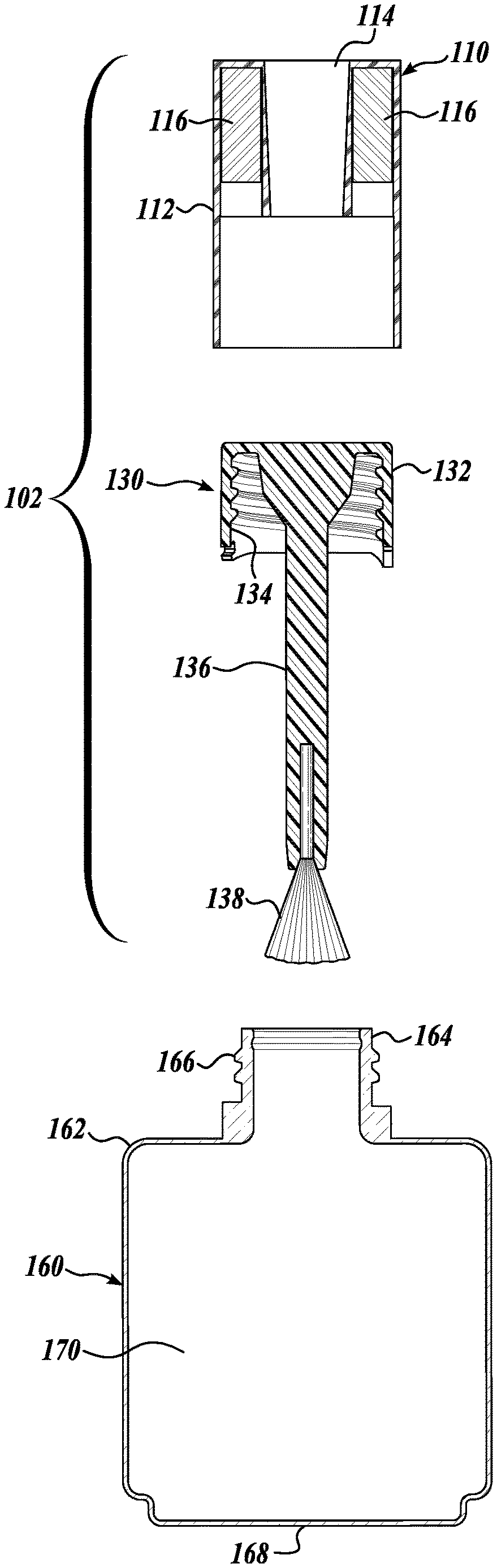
[0018] FIG. 2 is an exploded, cutaway view of the cosmetic formula container of FIG. 1;
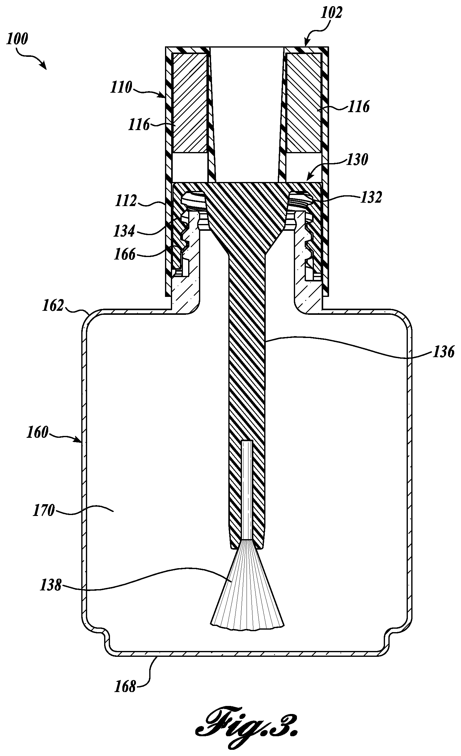
[0019] FIG. 3 is an assembled, cutaway view of the cosmetic formula container of FIG. 1;
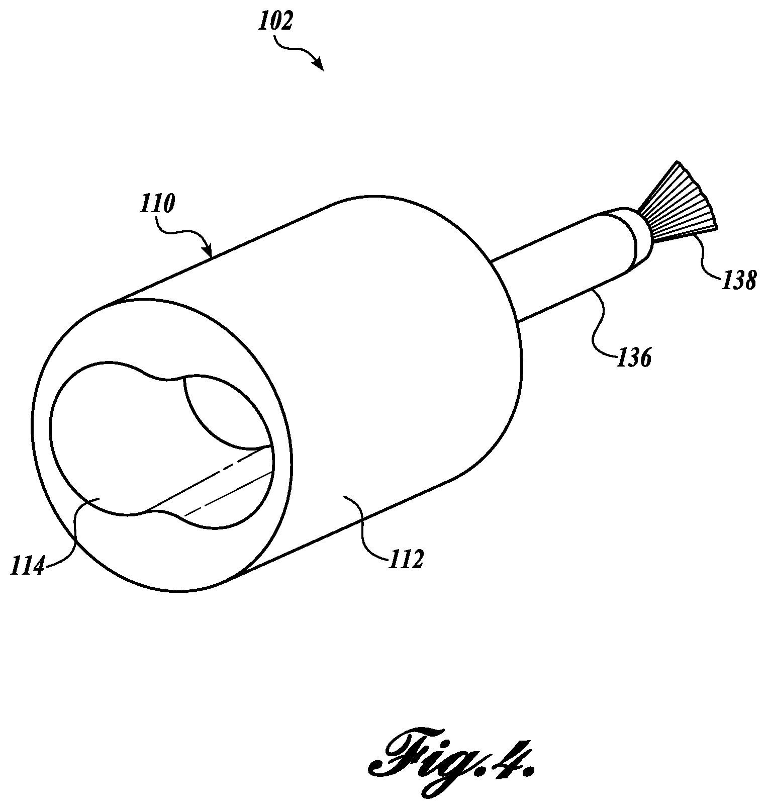
[0020] FIG. 4 is a perspective view of the applicator cap with an interconnect feature of FIG. 1; and
[0021] FIG. 5 is a cutaway view of the applicator cap with an interconnect feature of FIG. 1.
DETAILED DESCRIPTION
[0022] The following description provides several examples that relate to cosmetic applicators and containers. Application of a wide variety of cosmetic formulas to the human body is a common practice, including eyelashes, eyelids, eyebrows, fingernails, toenails, lips, and other body parts. Some examples of such cosmetic formula include mascara, eyeliner, eye shadow, nail polish, shellac, glitter, clearcoat, nail supplements, nail proteins, lipstick, lip gloss, etc. To apply the cosmetic formula, an applicator can be used. Generally described, an applicator includes a brush or a similarly structured portion at one end of the applicator that retains formula for application to the body part. The opposite end of the applicator may be integrated into a cap for the cosmetic container and is grasped during use. For users who are self-applying the cosmetic formula, improving ergonomics may, for example, ease the transition from the dominant hand to the non-dominant hand during application. In this regard, the ergonomics may be further improved by providing an increased grasping area for the user.
[0023] FIG. 1 shows one representative embodiment of a cosmetic formula container having an applicator cap with an interconnect feature for implementing one or more methodologies or technologies, such as, for example, providing improved ergonomics for the user. In an example, the applicator cap may couple to an extension handle through the interconnect feature. Conventional applicators are unable to readily couple to such an extension handle without an adaptor, which typically increases the length of the overall combination and detrimentally affects ergonomics.
[0024] Accordingly, to address the deficiencies in conventional applicators, and others, embodiments of the present disclosure relate to an applicator cap with an interconnect feature to attach the applicator cap to a handle, such as an articulating handle, that provides improved ergonomics for use with both a user's left and right hands. To achieve these benefits and others, embodiments of the applicator cap disclosed herein include an interconnect feature.
[0025] The embodiments illustrated in the FIGURES have been designed for use with cosmetic formulas applied to the user's eyelashes, eyelids, eyebrows, fingernails, toenails, lips, etc. (e.g., mascara, eyeliner, eye shadow, polish, shellac, glitter, clearcoat, supplements, protein, lipstick, lip gloss, etc.). Embodiments of the present disclosure are also suitable for applying a cosmetic formula to any surface of the user's body.
[0026] Embodiments of the applicator cap disclosed herein are suitable for use with standard cosmetic formula bottles, among others. In one embodiment, the cosmetic formula bottle generally includes a neck and an interior cavity configured to hold a quantity of cosmetic formula. The neck is configured to interface with a cap in a removably couplable manner for enclosing the cosmetic formula within the bottle. In one embodiment, the cap is adapted to be coupled to the applicator cap. In certain embodiments disclosed herein, the cosmetic formula bottle is about 15 centimeters or smaller in height, about 7.5 centimeters or smaller in width or diameter, and contains less than 0.5 liters of cosmetic formula. In an embodiment, a major dimension of the cosmetic formula bottle ranges from about 2 centimeters to about 15 centimeters. In an embodiment, a major dimension of the cosmetic formula bottle ranges from about 2 centimeters to about 7 centimeters. In an embodiment, the volume of the cosmetic formula bottle ranges from about 0.08 fluid ounces (fl. oz.) to about 20 fl. oz. In an embodiment, the volume of the cosmetic formula bottle ranges from about 0.08 fluid ounces (fl. oz.) to about 3 fl. oz. In an embodiment, the volume of the cosmetic formula bottle ranges from about 0.08 fluid ounces (fl. oz.) to about 1 fl. oz. In an embodiment, the volume of the cosmetic formula bottle ranges from about 0.08 fluid ounces (fl. oz.) to about 0.5 fl. oz. In an embodiment, the volume of the cosmetic formula bottle ranges from about 2.5 milliliters (ml) to about 600 ml. In an embodiment, the volume of the cosmetic formula bottle ranges from about 2.5 milliliters (ml) to about 100 ml. In an embodiment, the volume of the cosmetic formula bottle ranges from about 2.5 milliliters (ml) to about 50 ml. In an embodiment, the volume of the cosmetic formula bottle ranges from about 2.5 milliliters (ml) to about 15 ml.
[0027] Referring now to FIGS. 1-3, there is shown one embodiment of a cosmetic formula container, generally designated 100, in accordance with one or more aspects of the present disclosure. In the illustrated embodiment, the cosmetic formula container 100 includes an applicator cap assembly 102, having a cap portion 110 and an applicator 130, and a cosmetic bottle 160. In some embodiments, the applicator cap assembly 102 comprises multiple pieces, such as the cap portion 110 and the applicator 130 having a coupling portion 132 and an applicator stem 136. When the applicator cap assembly 102 is assembled, the applicator 130 includes features to removably couple to the cosmetic bottle 160, and the applicator stem 136 extends into the interior of the cosmetic bottle 160. In some embodiments, the applicator stem 136 can be directly coupled to the cap portion 110, omitting the coupling portion 132. In other embodiments, the applicator stem 136 is a separate device, which is not coupled to the cap portion 110. In further embodiments, the applicator 130 does not include a stem, for example, when the applicator is a sponge type applicator for applying a cosmetic formula to a face.
[0028] Still generally referring to FIGS. 1-3, each component of the container 100 will be described in more detail. The FIGURES illustrate one or more embodiments of the applicator cap assembly 102 in accordance with aspects of the present disclosure. As shown in FIG. 1, the applicator cap assembly 102 includes the applicator stem 136 having a plurality of bristles 138 fixedly secured to an end distal to the cap portion 110. To aid in fixedly securing the plurality of bristles 138 to the applicator stem 136, a bristle cavity (not shown) may be provided. In other embodiments, the applicator stem 136 includes a flocked surface (not shown) on the application end of the applicator stem 136, or any other surface configured to retain a portion of the cosmetic formula for application to the body.
[0029] The applicator stem 136 is of suitable length and diameter for the plurality of bristles 138 to interface the cosmetic formula within the cosmetic bottle 160. In this regard, in some embodiments, the applicator stem 136 is of a length such that the free ends of the plurality of bristles 138 contact an interior bottom of the cosmetic bottle 160 when the cosmetic formula container 100 is closed. In other embodiments, the applicator stem 136 is of a length such that the free ends of the plurality of bristles 138 are between about 1 millimeter and about 25 millimeters away from the interior bottom of the cosmetic bottle 160 when the cosmetic formula container 100 is closed. In further embodiments, the applicator stem 136 is of a length such that the free ends of the plurality of bristles 138 are between about 1 millimeter and about 5 millimeters away from the interior bottom of the cosmetic bottle 160 when the cosmetic formula container 100 is closed. The applicator stem 136 has a diameter suitable to pass through a neck 164 of the cosmetic bottle 160 to interface the cosmetic formula therein.
[0030] As described above, embodiments of the cosmetic container 100 include the applicator cap assembly 102 and a cosmetic bottle 160. The cosmetic bottle 160 includes bottle body 162 that forms an interior cavity 170 configured to hold a preselected quantity of cosmetic formula. Non-limiting examples of formulas include cosmetic formulations, treatment formulations, mascara, eye shadow, eyeliner, nail care formulation, cosmetic products, care products, nail polish cosmetic compositions, Ultraviolet (UV) curable cosmetic nail gel compositions, anti-fungal compositions, color cosmetic compositions, nail care cosmetic formulations, lip care cosmetic formulations, eye cosmetic formulations, eye treatment compositions, and the like. Although one type of cosmetic bottle 160 is illustrated and described herein, any suitable shape, size, and design of a cosmetic container may be used with the embodiments of the present disclosure.
[0031] Further non-limiting examples of formulas include cuticle care formulations (e.g., apricot cuticle oil formations, hydrating formulations, and the like); based coat formulations (e.g., strengtheners, rubber adhesives, primers, color adhesives, anti-break compositions, ridge fillers, and the like); treatment formulations (e.g., nutra-keratin formulations, bamboo extract formulations, ridge filler formulations, anti-chip formulations, and the like); top coat formulations (e.g., GEL SETTER.TM., shine, polish, matte finisher, anti-chip, color adhesive, primer, quick drying, and the like); and the like. In one embodiment, the cosmetic formula includes nail care cosmetic compositions.
[0032] The cosmetic bottle also includes the neck 164 for interfacing with the cap portion 110 and the applicator 130. In some embodiments, the neck 164 extends from the bottle body 162 with a smaller cross-section than the bottle body 162. The applicator cap assembly 102 selectively attaches to the neck 164 of the cosmetic bottle 160 using a mechanical coupling, such as press fit, turn to lock, threads, interlock, etc. In the illustrated embodiment shown in FIG. 3, the applicator cap assembly 102 selectively attaches via a coupling portion, e.g., internal applicator threads 134, that engage the cooperatingly configured bottle threads 166 disposed on the neck 164. In several embodiments, the applicator cap assembly 102 is configured to closely interface with the neck 164 to provide a hermetic seal, keeping the cosmetic formula from escaping the bottle cavity 170, evaporating, etc.
[0033] In some embodiments, the cap portion 110 is adapted to be coupled to the applicator 130 to form the applicator cap assembly 102. In the embodiment shown, the applicator 130 is coupled to the cap portion 110 via the coupling portion 132. In this regard, the cap portion 110 and the applicator 130, in some embodiments, function as a single unit during application of the cosmetic formula to the user. In other embodiments, the cap portion 110 is integral to the applicator 130 such that together the components form a single unit. Still, in other embodiments, the applicator 130 remains a separate component such that the cap portion 110 is removed from the cosmetic bottle 160 to reveal the applicator 130 prior to application of the cosmetic formula.
[0034] Embodiments of cap portion 110 will now be described with reference to the FIGURES. Referring initially to FIG. 5, the cap portion 110 includes a cap 112 having an interconnect cavity 114 configured to interface an ergonomic handle H. In the illustrated embodiment, the interconnect cavity 114 is configured as a female cavity adapted to receive a male protrusion of the ergonomic handle H. As shown in FIG. 4, the interconnect cavity 114 of the cap portion 110 is shaped irregularly in cross-section to interface the ergonomic handle H such that the applicator cap assembly 102 does not turn with respect to the ergonomic handle H during use. In this regard, the illustrated embodiment of the interconnect cavity 114 is a "kidney" shape. In other embodiments, the interconnect cavity 114 is suitably any shape configured to interface the ergonomic handle H.
[0035] In some embodiments, the cap portion 110 includes a feature to releasably couple and retain the applicator cap assembly 102 in position on the ergonomic handle H. In these embodiments, the retention feature or retainer is any suitable feature to prevent inadvertent detachment of the applicator cap assembly 102 from the ergonomic handle H. In this regard, the retainer creates a connection between the applicator cap assembly 102 and the ergonomic handle H that has a higher separation force required to release the applicator cap assembly 102 from the ergonomic handle H than the separation force required without the retainer. In the illustrated embodiment, the cap portion 110 includes a magnetic retainer having magnets 116. The orientation and polarity of the magnets 116 is configured to interface one or more magnets in the ergonomic handle H to provide a readily releasable coupling of the applicator cap assembly 102 to the ergonomic handle H. In other embodiments, the cap portion 110 includes a retainer having threads, press fit, snap fit, clearance fit, etc. In these embodiments, suitable cooperating features are included on the ergonomic handle H to create the releasable coupling.
[0036] The ergonomic handle H may be configured to detect the type of applicator cap assembly upon connection to adjust settings based on the type of connection. In this regard, the applicator assembly 102 may be configured with an identification feature. In some embodiments, a data storage device, such as an RFID chip, may be embedded in the cap portion 110 to communicate with a sensor in the ergonomic handle H and provide information related to the type of applicator, the cosmetic formula being applied, environmental data, user preferences, authenticity of the product, expiration date, opening date, among other information. In other embodiments, the polarity of the magnets 116 may provide information to the ergonomic handle H.
[0037] In some embodiments, the ergonomic handle H is configured to position the applicator cap assembly 102 at various angles upon detection of the type of cosmetic formula being applied to the body. In this regard, for example, during an application to eyelashes, the applicator cap assembly 102 may be oriented substantially horizontal with respect to the ground, or between 45.degree. and 90.degree. with respect to the ergonomic handle H. In another example, during application to lips, the applicator cap assembly 102 may be oriented between 30.degree. and 80.degree., or between 45.degree. and 60.degree. from horizontal with respect to the ground. In a further example, during application to nails, the applicator cap assembly 102 may be oriented at about 45.degree. from horizontal with respect to the ground, or between 0.degree. and 60.degree. with respect to the ergonomic handle H. In another example, during application to the face, the applicator cap assembly 102 may be oriented between 0.degree. and 90.degree. with respect to the ergonomic handle H. As will be appreciated, other positioning of the applicator cap assembly 102 is also within the scope of the present disclosure. In other embodiments, the ergonomic handle H is configured to mechanically remove the applicator cap assembly 102 from the bottle 160, such as by motorized unscrewing of the applicator cap assembly 102.
[0038] Returning to FIGS. 1-3, one embodiment of the coupling portion 132 will be described in more detail. The coupling portion 132 provides one representative technique for coupling the applicator 130 to the cap portion 110, although other techniques or methodologies can be practiced with embodiments of the present disclosure. As shown in FIGS. 1-3, the coupling portion 132 configured to interface with the cap portion 110 and retain the coupling portion 132 therewith. In this regard, the coupling portion 132 interfaces with the cap portion 110 using a press fit, threads, glue, or any other suitable mechanical coupling. In some embodiments, the stem 136 is formed from the coupling portion 132 to form the applicator 130. In other embodiments, the stem 136 forms a separate piece from the coupling portion 132.
[0039] The detailed description set forth above in connection with the appended drawings, where like numerals reference like elements, are intended as a description of various embodiments of the present disclosure and are not intended to represent the only embodiments. Each embodiment described in this disclosure is provided merely as an example or illustration and should not be construed as preferred or advantageous over other embodiments. The illustrative examples provided herein are not intended to be exhaustive or to limit the disclosure to the precise forms disclosed. Similarly, any steps described herein may be interchangeable with other steps, or combinations of steps, in order to achieve the same or substantially similar result.
[0040] In the foregoing description, specific details are set forth to provide a thorough understanding of exemplary embodiments of the present disclosure. It will be apparent to one skilled in the art, however, that the embodiments disclosed herein may be practiced without embodying all of the specific details. In some instances, well-known process steps have not been described in detail in order not to unnecessarily obscure various aspects of the present disclosure. Further, it will be appreciated that embodiments of the present disclosure may employ any combination of features described herein.
[0041] The present application may include references to directions, such as "forward," "rearward," "front," "back," "upward," "downward," "right hand," "left hand," "lateral," "medial," "in," "out," "extended," "advanced," "retracted," "proximal," "distal," "central," etc. These references, and other similar references in the present application, are only to assist in helping describe and understand the particular embodiment and are not intended to limit the present disclosure to these directions or locations.
[0042] The present application may also reference quantities and numbers. Unless specifically stated, such quantities and numbers are not to be considered restrictive, but exemplary of the possible quantities or numbers associated with the present application. Also in this regard, the present application may use the term "plurality" to reference a quantity or number. In this regard, the term "plurality" is meant to be any number that is more than one, for example, two, three, four, five, etc. The term "about," "approximately," etc., means plus or minus 5% of the stated value. For the purposes of the present disclosure, the phrase "at least one of A, B, and C," for example, means (A), (B), (C), (A and B), (A and C), (B and C), or (A, B, and C), including all further possible permutations when greater than three elements are listed.
[0043] The principles, representative embodiments, and modes of operation of the present disclosure have been described in the foregoing description. However, aspects of the present disclosure, which are intended to be protected, are not to be construed as limited to the particular embodiments disclosed. Further, the embodiments described herein are to be regarded as illustrative rather than restrictive. It will be appreciated that variations and changes may be made by others, and equivalents employed, without departing from the spirit of the present disclosure. Accordingly, it is expressly intended that all such variations, changes, and equivalents fall within the spirit and scope of the present disclosure as claimed.
* * * * *
D00000
D00001
D00002
D00003
D00004
D00005
XML
uspto.report is an independent third-party trademark research tool that is not affiliated, endorsed, or sponsored by the United States Patent and Trademark Office (USPTO) or any other governmental organization. The information provided by uspto.report is based on publicly available data at the time of writing and is intended for informational purposes only.
While we strive to provide accurate and up-to-date information, we do not guarantee the accuracy, completeness, reliability, or suitability of the information displayed on this site. The use of this site is at your own risk. Any reliance you place on such information is therefore strictly at your own risk.
All official trademark data, including owner information, should be verified by visiting the official USPTO website at www.uspto.gov. This site is not intended to replace professional legal advice and should not be used as a substitute for consulting with a legal professional who is knowledgeable about trademark law.