Method, System and Apparatus for Adaptive Ceiling-Based Localization
Mazaheri Tehrani; Mehdi ; et al.
U.S. patent application number 16/429586 was filed with the patent office on 2020-12-03 for method, system and apparatus for adaptive ceiling-based localization. The applicant listed for this patent is ZEBRA TECHNOLOGIES CORPORATION. Invention is credited to Feng Cao, Tze Fung Christopher Chan, Mehdi Mazaheri Tehrani, Mahyar Vajedi.
| Application Number | 20200379480 16/429586 |
| Document ID | / |
| Family ID | 1000004156713 |
| Filed Date | 2020-12-03 |


| United States Patent Application | 20200379480 |
| Kind Code | A1 |
| Mazaheri Tehrani; Mehdi ; et al. | December 3, 2020 |
Method, System and Apparatus for Adaptive Ceiling-Based Localization
Abstract
A method in a navigational controller includes: controlling a ceiling-facing camera of a mobile automation apparatus to capture a stream of images of a facility ceiling; activating a primary localization mode including: (i) detecting primary features in the captured image stream; and (ii) updating, based on the primary features, an estimated pose of the mobile automation apparatus and a confidence level corresponding to the estimated pose; determining whether the confidence level exceeds a confidence threshold; when the confidence level does not exceed the threshold, switching to a secondary localization mode including: (i) detecting secondary features in the captured image stream; (ii) updating the estimated pose and the confidence level based on the secondary features; and (iii) searching the image stream for the primary features; and responsive to detecting the primary features in the image stream, re-activating the primary localization mode.
| Inventors: | Mazaheri Tehrani; Mehdi; (Brampton, CA) ; Vajedi; Mahyar; (Mississauga, CA) ; Cao; Feng; (Burlington, CA) ; Chan; Tze Fung Christopher; (Toronto, CA) | ||||||||||
| Applicant: |
|
||||||||||
|---|---|---|---|---|---|---|---|---|---|---|---|
| Family ID: | 1000004156713 | ||||||||||
| Appl. No.: | 16/429586 | ||||||||||
| Filed: | June 3, 2019 |
| Current U.S. Class: | 1/1 |
| Current CPC Class: | G05D 1/027 20130101; G05D 1/0253 20130101; G06K 9/6212 20130101; G05D 1/0094 20130101 |
| International Class: | G05D 1/02 20060101 G05D001/02; G05D 1/00 20060101 G05D001/00; G06K 9/62 20060101 G06K009/62 |
Claims
1. A method in a navigational controller, the method comprising: controlling a ceiling-facing camera of a mobile automation apparatus to capture a stream of images of a facility ceiling; activating a primary localization mode including: (i) detecting primary features in the captured image stream; and (ii) updating, based on the primary features, an estimated pose of the mobile automation apparatus and a confidence level corresponding to the estimated pose; determining whether the confidence level exceeds a confidence threshold; when the confidence level does not exceed the confidence threshold, switching to a secondary localization mode including: (i) detecting secondary features in the captured image stream; (ii) updating the estimated pose and the confidence level based on the secondary features; and (iii) searching the image stream for the primary features; and responsive to detecting the primary features in the image stream, re-activating the primary localization mode.
2. The method of claim 1, further comprising: when the confidence level exceeds the confidence threshold, outputting the estimated pose.
3. The method of claim 1, wherein detecting the primary features comprises detecting corner features.
4. The method of claim 1, wherein detecting the secondary features comprises detecting features corresponding to lamps on the facility ceiling.
5. The method of claim 4, wherein the secondary features include at least one of: point features corresponding to bulb-type lamps; and linear features corresponding to linear-type lamps.
6. The method of claim 5, further comprising: storing a configuration setting indicating which lamp types are active in the facility.
7. The method of claim 1, further comprising: responsive to updating the estimated pose and confidence level based on the secondary features, repeating the determination of whether the confidence level exceeds the confidence threshold; when the confidence level does not exceed the confidence threshold, switching to a backup localization mode including: (i) controlling a motion sensor to obtain odometry data; (ii) updating the estimated pose and confidence level based on the odometry data, and (iii) searching the image stream for the secondary features; and responsive to detecting the secondary features, re-activating the secondary localization mode.
8. A mobile automation apparatus comprising: a chassis; a ceiling-facing camera supported by the chassis; and a navigational controller configured to: control the ceiling-facing camera to capture a stream of images of a facility ceiling; activate a primary localization mode to: (i) detect primary features in the captured image stream; and (ii) update, based on the primary features, an estimated pose of the mobile automation apparatus and a confidence level corresponding to the estimated pose; determine whether the confidence level exceeds a confidence threshold; when the confidence level does not exceed the confidence threshold, switch to a secondary localization mode to: (i) detect secondary features in the captured image stream; (ii) update the estimated pose and the confidence level based on the secondary features; and (iii) search the image stream for the primary features; and responsive to detection of the primary features in the image stream, re-activate the primary localization mode.
9. The mobile automation apparatus of claim 8, wherein the navigational controller is further configured, when the confidence level exceeds the confidence threshold, to output the estimated pose.
10. The mobile automation apparatus of claim 8, wherein the navigational controller is further configured, in order to detect the primary features, to detect corner features.
11. The mobile automation apparatus of claim 8, wherein the navigational controller is further configured, in order to detect the secondary features, to detect features corresponding to lamps on the facility ceiling.
12. The mobile automation apparatus of claim 11, wherein the secondary features include at least one of: point features corresponding to bulb-type lamps; and linear features corresponding to linear-type lamps.
13. The mobile automation apparatus of claim 12, further comprising: a memory storing a configuration setting indicating which lamp types are active in the facility.
14. The mobile automation apparatus of claim 8, wherein the navigational controller is further configured to: responsive to updating of the estimated pose and confidence level based on the secondary features, repeat the determination of whether the confidence level exceeds the confidence threshold; when the confidence level does not exceed the confidence threshold, switch to a backup localization mode to: (i) control a motion sensor to obtain odometry data; (ii) update the estimated pose and confidence level based on the odometry data, and (iii) search the image stream for the secondary features; and responsive to detection of the secondary features, re-activate the secondary localization mode.
15. A method in a navigational controller, the method comprising: controlling a camera of a mobile automation apparatus to capture a stream of images in a facility; updating an estimated pose of the mobile automation apparatus based on one of primary features and secondary features detected in the images; and selecting whether to detect one of the primary features and the secondary features in the images according to a confidence level associated with the estimated pose.
16. The method of claim 15, further comprising controlling the camera to capture the images using constant capture parameters.
17. The method of claim 16, wherein the capture parameters include a shutter speed and an exposure setting.
18. The method of claim 15, wherein the camera faces a ceiling of the facility.
19. The method of claim 15, wherein the primary features include corner features, and wherein the secondary features correspond to lamps.
20. The method of claim 15, wherein the selecting includes selecting to detect the secondary features when the confidence level associated with the estimated pose falls below a predefined threshold.
Description
BACKGROUND
[0001] Environments in which objects are managed, such as retail facilities, warehousing and distribution facilities, and the like, may be complex and fluid. For example, a retail facility may include objects such as products for purchase, and a distribution facility may include objects such as parcels or pallets. The visual and structural features of such facilities may also vary widely. A mobile automation apparatus may be deployed within such facilities to perform tasks at various locations. For example, a mobile automation apparatus may be deployed to capture data relating to these objects at various locations in a retail, warehousing, or distribution facility. To navigate to the appropriate locations, the mobile automation apparatus may track its own location within the facility. The complexity and variability of the facility may reduce the accuracy of the apparatus' localization.
BRIEF DESCRIPTION OF THE SEVERAL VIEWS OF THE DRAWINGS
[0002] The accompanying figures, where like reference numerals refer to identical or functionally similar elements throughout the separate views, together with the detailed description below, are incorporated in and form part of the specification, and serve to further illustrate embodiments of concepts that include the claimed invention, and explain various principles and advantages of those embodiments.
[0003] FIG. 1 is a schematic of a mobile automation system.
[0004] FIG. 2 depicts a mobile automation apparatus in the system of FIG. 1.
[0005] FIG. 3 is a block diagram of certain internal components of the mobile automation apparatus in the system of FIG. 1.
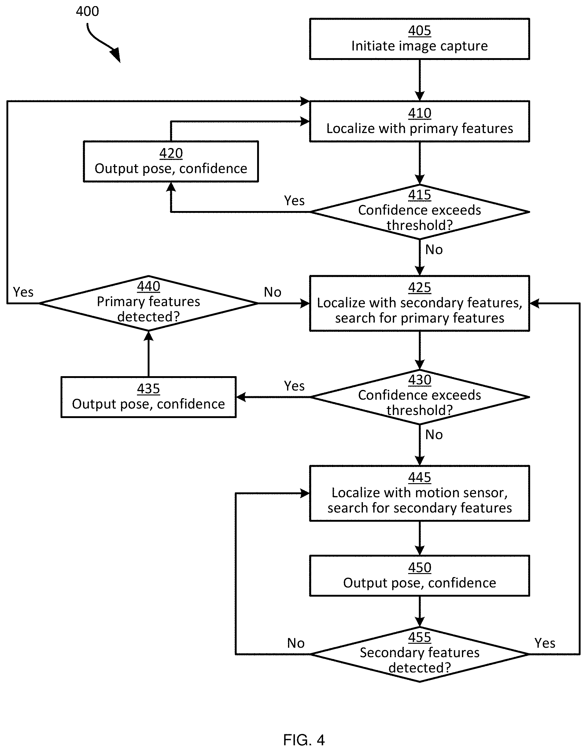
[0006] FIG. 4 is a flowchart of a method of adaptive ceiling-based localization in the system of FIG. 1.
[0007] FIG. 5 is a diagram illustrating localization in a primary localization mode according to the method of FIG. 4.
[0008] FIG. 6 is a diagram illustrating conditions preventing primary localization according to the method of FIG. 4.
[0009] FIG. 7 is a diagram illustrating localization in a secondary localization mode according to the method of FIG. 4.
[0010] FIG. 8 is a diagram illustrating conditions preventing secondary localization according to the method of FIG. 4.
[0011] Skilled artisans will appreciate that elements in the figures are illustrated for simplicity and clarity and have not necessarily been drawn to scale. For example, the dimensions of some of the elements in the figures may be exaggerated relative to other elements to help to improve understanding of embodiments of the present invention.
[0012] The apparatus and method components have been represented where appropriate by conventional symbols in the drawings, showing only those specific details that are pertinent to understanding the embodiments of the present invention so as not to obscure the disclosure with details that will be readily apparent to those of ordinary skill in the art having the benefit of the description herein.
DETAILED DESCRIPTION
[0013] Examples disclosed herein are directed to a method in a navigational controller including: controlling a ceiling-facing camera of a mobile automation apparatus to capture a stream of images of a facility ceiling; activating a primary localization mode including: (i) detecting primary features in the captured image stream; and (ii) updating, based on the primary features, an estimated pose of the mobile automation apparatus and a confidence level corresponding to the estimated pose; determining whether the confidence level exceeds a confidence threshold; when the confidence level does not exceed the threshold, switching to a secondary localization mode including: (i) detecting secondary features in the captured image stream; (ii) updating the estimated pose and the confidence level based on the secondary features; and (iii) searching the image stream for the primary features; and responsive to detecting the primary features in the image stream, re-activating the primary localization mode.
[0014] Additional examples disclosed herein are directed to a mobile automation apparatus comprising: a chassis; a ceiling-facing camera supported by the chassis; and
[0015] a navigational controller configured to: control the ceiling-facing camera to capture a stream of images of a facility ceiling; activate a primary localization mode to:
[0016] (i) detect primary features in the captured image stream; and (ii) update, based on the primary features, an estimated pose of the mobile automation apparatus and a confidence level corresponding to the estimated pose; determine whether the confidence level exceeds a confidence threshold; when the confidence level does not exceed the threshold, switch to a secondary localization mode to: (i) detect secondary features in the captured image stream; (ii) update the estimated pose and the confidence level based on the secondary features; and (iii) search the image stream for the primary features; and responsive to detection of the primary features in the image stream, re-activate the primary localization mode.
[0017] Further examples disclosed herein are directed to a method in a navigational controller, the method comprising: controlling a camera of a mobile automation apparatus to capture a stream of images in a facility; updating an estimated pose of the mobile automation apparatus based on one of primary features or secondary features detected in the images; and selecting whether to detect the primary features or the secondary features in the images according to a confidence level associated with the estimated pose.
[0018] FIG. 1 depicts a mobile automation system 100 in accordance with the teachings of this disclosure. The system 100 includes a server 101 in communication with at least one mobile automation apparatus 103 (also referred to herein simply as the apparatus 103) and at least one client computing device 104 via communication links 105, illustrated in the present example as including wireless links. In the present example, the links 105 are provided by a wireless local area network (WLAN) deployed via one or more access points (not shown). In other examples, the server 101, the client device 104, or both, are located remotely (i.e. outside the environment in which the apparatus 103 is deployed), and the links 105 therefore include wide-area networks such as the Internet, mobile networks, and the like. The system 100 also includes a dock 106 for the apparatus 103 in the present example. The dock 106 is in communication with the server 101 via a link 107 that in the present example is a wired link. In other examples, however, the link 107 is a wireless link.
[0019] The client computing device 104 is illustrated in FIG. 1 as a mobile computing device, such as a tablet, smart phone or the like. In other examples, the client device 104 is implemented as another type of computing device, such as a desktop computer, a laptop computer, another server, a kiosk, a monitor, and the like. The system 100 can include a plurality of client devices 104 in communication with the server 101 via respective links 105.
[0020] The system 100 is deployed, in the illustrated example, in a retail facility including a plurality of support structures such as shelf modules 110-1, 110-2, 110-3 and so on (collectively referred to as shelf modules 110 or shelves 110, and generically referred to as a shelf module 110 or shelf 110--this nomenclature is also employed for other elements discussed herein). Each shelf module 110 supports a plurality of products 112. Each shelf module 110 includes a shelf back 116-1, 116-2, 116-3 and a support surface (e.g. support surface 117-3 as illustrated in FIG. 1) extending from the shelf back 116 to a shelf edge 118-1, 118-2, 118-3.
[0021] The shelf modules 110 are typically arranged in a plurality of aisles, each of which includes a plurality of modules 110 aligned end-to-end. In such arrangements, the shelf edges 118 face into the aisles, through which customers in the retail facility, as well as the apparatus 103, may travel. As will be apparent from FIG. 1, the term "shelf edge" 118 as employed herein, which may also be referred to as the edge of a support surface (e.g., the support surfaces 117) refers to a surface bounded by adjacent surfaces having different angles of inclination. In the example illustrated in FIG. 1, the shelf edge 118-3 is at an angle of about ninety degrees relative to the support surface 117-3 and to the underside (not shown) of the support surface 117-3. In other examples, the angles between the shelf edge 118-3 and the adjacent surfaces, such as the support surface 117-3, is more or less than ninety degrees.
[0022] The apparatus 103 is equipped with a plurality of navigation and data capture sensors 108, such as image sensors (e.g. one or more digital cameras) and depth sensors (e.g. one or more Light Detection and Ranging (LIDAR) sensors, one or more depth cameras employing structured light patterns, such as infrared light, or the like). The apparatus 103 is deployed within the retail facility and, via communication with the server 101 and use of the sensors 108, navigates autonomously or partially autonomously along a length 119 of at least a portion of the shelves 110.
[0023] While navigating among the shelves 110, the apparatus 103 can capture images, depth measurements and the like, representing the shelves 110 (generally referred to as shelf data or captured data). Navigation may be performed according to a frame of reference 102 established within the retail facility. The apparatus 103 therefore tracks its pose (i.e. location and orientation) in the frame of reference 102. The process of updating the current pose of the apparatus 103 relative to the frame of reference 102 is also referred to as localization. As will be discussed below, the apparatus 103 implements a plurality of localization modes, and switches between those localization modes under various conditions in order to maintain an accurate pose estimate under a wide variety of environmental and operational conditions.
[0024] The server 101 includes a special purpose controller, such as a processor 120, specifically designed to control and/or assist the mobile automation apparatus 103 to navigate the environment and to capture data. The processor 120 is interconnected with a non-transitory computer readable storage medium, such as a memory 122, having stored thereon computer readable instructions for performing various functionality, including control of the apparatus 103 to navigate the modules 110 and capture shelf data, as well as post-processing of the shelf data. The memory 122 can also store data for use in the above-mentioned control of the apparatus 103, such as a repository 123 containing a map of the retail environment and any other suitable data (e.g. operational constraints for use in controlling the apparatus 103, data captured by the apparatus 103, and the like).
[0025] The memory 122 includes a combination of volatile memory (e.g. Random Access Memory or RAM) and non-volatile memory (e.g. read only memory or ROM, Electrically Erasable Programmable Read Only Memory or EEPROM, flash memory). The processor 120 and the memory 122 each comprise one or more integrated circuits. In some embodiments, the processor 120 is implemented as one or more central processing units (CPUs) and/or graphics processing units (GPUs).
[0026] The server 101 also includes a communications interface 124 interconnected with the processor 120. The communications interface 124 includes suitable hardware (e.g. transmitters, receivers, network interface controllers and the like) allowing the server 101 to communicate with other computing devices--particularly the apparatus 103, the client device 104 and the dock 106--via the links 105 and 107. The links 105 and 107 may be direct links, or links that traverse one or more networks, including both local and wide-area networks. The specific components of the communications interface 124 are selected based on the type of network or other links that the server 101 is required to communicate over. In the present example, as noted earlier, a wireless local-area network is implemented within the retail facility via the deployment of one or more wireless access points. The links 105 therefore include either or both wireless links between the apparatus 103 and the mobile device 104 and the above-mentioned access points, and a wired link (e.g. an Ethernet-based link) between the server 101 and the access point.
[0027] The processor 120 can therefore obtain data captured by the apparatus 103 via the communications interface 124 for storage (e.g. in the repository 123) and subsequent processing (e.g. to detect objects such as shelved products in the captured data, and detect status information corresponding to the objects). The server 101 may also transmit status notifications (e.g. notifications indicating that products are out-of-stock, in low stock or misplaced) to the client device 104 responsive to the determination of product status data. The client device 104 includes one or more controllers (e.g. central processing units (CPUs) and/or field-programmable gate arrays (FPGAs) and the like) configured to process (e.g. to display) notifications received from the server 101.
[0028] Turning now to FIG. 2, the mobile automation apparatus 103 is shown in greater detail. The apparatus 103 includes a chassis 201 containing a locomotive assembly 203 (e.g. one or more electrical motors driving wheels, tracks or the like). The apparatus 103 further includes a sensor mast 205 supported on the chassis 201 and, in the present example, extending upwards (e.g., substantially vertically) from the chassis 201. The mast 205 supports the sensors 108 mentioned earlier. In particular, the sensors 108 include at least one imaging sensor 207, such as a digital camera. In the present example, the mast 205 supports seven digital cameras 207-1 through 207-7 oriented to face the shelves 110. The mast 205 also supports a ceiling-facing camera 208 having a field of view oriented upwards, towards a ceiling of the retail facility. As will be discussed in greater detail below, images captured by the camera 208 are employed by the apparatus 103 for localization.
[0029] The mast 205 also supports at least one depth sensor 209, such as a 3D digital camera capable of capturing both depth data and image data. The apparatus 103 also includes additional depth sensors, such as LIDAR sensors 211. In the present example, the mast 205 supports two LIDAR sensors 211-1 and 211-2. As shown in FIG. 2, the cameras 207 and the LIDAR sensors 211 are arranged on one side of the mast 205, while the depth sensor 209 is arranged on a front of the mast 205. That is, the depth sensor 209 is forward-facing (i.e. captures data in the direction of travel of the apparatus 103), while the cameras 207 and LIDAR sensors 211 are side-facing (i.e. capture data alongside the apparatus 103, in a direction perpendicular to the direction of travel). In other examples, the apparatus 103 includes additional sensors, such as one or more RFID readers, temperature sensors, and the like.
[0030] The mast 205 also supports a plurality of illumination assemblies 213, configured to illuminate the fields of view of the respective cameras 207. That is, the illumination assembly 213-1 illuminates the field of view of the camera 207-1, and so on. The sensors 207 and 211 are oriented on the mast 205 such that the fields of view of the sensors each face a shelf 110 along the length 119 of which the apparatus 103 is traveling. As noted earlier, the apparatus 103 is configured to track a pose of the apparatus 103 (e.g. a location and orientation of the center of the chassis 201) in the frame of reference 102, permitting data captured by the apparatus 103 to be registered to the frame of reference 102 for subsequent processing.
[0031] Referring to FIG. 3, certain components of the mobile automation apparatus 103 are shown, in addition to the cameras 207 and 208, depth sensor 209, lidars 211, and illumination assemblies 213 mentioned above. The apparatus 103 includes a special-purpose controller, such as a processor 300, interconnected with a non-transitory computer readable storage medium, such as a memory 304. The memory 304 includes a suitable combination of volatile memory (e.g. Random Access Memory or RAM) and non-volatile memory (e.g. read only memory or ROM, Electrically Erasable Programmable Read Only Memory or EEPROM, flash memory). The processor 300 and the memory 304 each comprise one or more integrated circuits. The memory 304 stores computer readable instructions for execution by the processor 300. In particular, the memory 304 stores a localization application 308 which, when executed by the processor 300, configures the processor 300 to perform various functions related to tracking the pose of the apparatus 103 within the facility. In particular, execution of the application 308 configures the processor 300 to maintain an updated pose estimate for the apparatus 103, based on data received from the sensors 108, and also to switch between the above-mentioned localization modes in update the pose estimate.
[0032] The processor 300, when so configured by the execution of the application 308, may also be referred to as a navigational controller 300. Those skilled in the art will appreciate that the functionality implemented by the processor 300 via the execution of the application 308 may also be implemented by one or more specially designed hardware and firmware components, such as FPGAs, ASICs and the like in other embodiments.
[0033] The memory 304 may also store a repository 312 containing, for example, a map of the environment in which the apparatus 103 operates, for use during the execution of the application 308. In addition, the apparatus 103 can (e.g. via execution of the application 308) update the map in the repository 312, in a process referred to as simultaneous localization and mapping (SLAM). The apparatus 103 also includes a communications interface 316 enabling the apparatus 103 to communicate with the server 101 (e.g. via the link 105 or via the dock 106 and the link 107), for example to receive instructions to navigate to specified locations and initiate data capture operations.
[0034] In addition to the sensors mentioned earlier, the apparatus 103 includes a motion sensor 318, such as one or more wheel odometers coupled to the locomotive assembly 203. The motion sensor 318 can also include, in addition to or instead of the above-mentioned wheel odometer(s), an inertial measurement unit (IMU) configured to measure acceleration along a plurality of axes.
[0035] FIG. 3 also illustrates certain components of the application 308. As will be apparent to those skilled in the art, the components of the application 308 can also be implemented as a suite of distinct applications, or in other subcombinations than that shown in FIG. 3.
[0036] The application 308, in the present example, includes a data capture controller 320 that controls the sensors of the apparatus 108 to obtain data for subsequent processing by the remaining components of the application 308. For example, the data capture controller 320 controls the camera 208 to capture a stream of images, and can also control the motion sensor to capture wheel odometry data, acceleration measurements, or the like.
[0037] The data obtained by the data capture controller 320 is provided to either or both of a pose estimator 324 and a set of feature detectors 328. The pose estimator 324 executes any suitable mechanism, or combination of mechanisms, to generate an estimated pose of the apparatus 103 according to the frame of reference 102, as well as a confidence level associated with the estimated pose. The pose estimator 324 can generate the estimated pose and confidence directly from sensor data received from the data capture controller 320 under some conditions. Under other conditions, the pose estimator 324 generates the pose and confidence based on features detected in the sensor data by the feature detectors 328. Two feature detectors 328-1 and 328-2 are shown in the illustrated example, but in other embodiments a greater number of feature detectors 328 may be implemented. The pose estimator 324 also controls the activity of the feature detectors 328, as will be discussed in greater detail below, enabling or disabling the feature detectors 328 depending on the active localization mode.
[0038] The actions performed by the apparatus 103, and specifically by the processor 300 as configured via execution of the application 308, to maintain an updated pose estimate of the apparatus in the frame of reference 102 will now be discussed in greater detail, with reference to FIG. 4. FIG. 4 illustrates a method 400 of adaptive ceiling-based localization, which will be described in conjunction with its performance in the system 100, and in particular by the apparatus 103, with reference to the components illustrated in FIGS. 2 and 3. As will be apparent in the discussion below, in other examples, some or all of the processing performed by the server 101 may be performed by the apparatus 103, and some or all of the processing performed by the apparatus 103 may be performed by the server 101.
[0039] In general, via the performance of the method 400, the apparatus 103 implements at least two localization modes (three modes are discussed in the example below). In each localization mode, the apparatus 103 detects distinct types of features present in the retail facility from captured sensor data, and updates the estimated pose of the apparatus 103 based on the detected features. The apparatus 103 additionally monitors certain conditions and switches between localization modes when such conditions are met.
[0040] Beginning at block 405, the apparatus 103 initiates capture of an image stream via the camera 208. For example, the data capture controller 320 shown in FIG. 3 can control the camera 208 to begin capturing a stream of images at any suitable rate, e.g. 30 frames per second. The captured images can be stored in the memory 304, and are obtained by the data capture controller 320 for further processing by the other components of the application 308. The capture of images continues throughout the performance of the method 400 as described below.
[0041] At block 410, the apparatus 103 performs localization via the detection of primary features in the images captured by the camera 208. In particular, the pose estimator 324 activates the primary feature detector 328-1. The primary feature detector 328-1, in turn, searches the image stream initiated at block 405 for primary features. Various forms of primary features are contemplated. In the present example, the primary features are corner-point features, detected via any suitable feature-tracking mechanism.
[0042] An example of such a mechanism, which also enables the application 308 to update the map in the repository 312 simultaneously with the localization functions discussed herein (i.e. which enables the apparatus 103 to perform SLAM), is ORB SLAM. In such an implementation, the primary feature detector 328-1 is an Oriented FAST and rotated BRIEF (ORB) feature detector configured to detect the positions of salient points in successive images of the image stream. Various other examples of SLAM mechanisms and feature detectors will be apparent to those skilled in the art.
[0043] Turning to FIG. 5, a side view of the apparatus 103 is shown adjacent to a shelf module 110. A ceiling 500 of the facility is also shown, and a field of view 504 of the camera 208 is illustrated. As shown in FIG. 5, various physical features present on the ceiling 500 are captured by the camera 208. An example image 508 captured at the position shown in FIG. 5 is illustrated in the upper portion of FIG. 5. As illustrated, the ceiling supports lamps in the form of bulb lamps 512 and linear lamps 516, as well as a sign 520 bearing text and/or other indicia. As shown in the image, the ceiling 500 may also include ridged elements 524 such as a support beams or the like. The lamps 512 and 516 are characterized by greater contrast relative to the ceiling 500 than the sign 520 as a result of the light emitted by the lamps 512 and 516. However, the lamps 512 typically lack clearly detectable edges or corners in images. The lamps 516 may be detectable as edge features (i.e. lines), but typically lack clearly detectable corner features in images. Further, the lamps 512 and 516 may occur in repeating patterns along the ceiling 500, complicating the task of determining the location of any individual lamp 512 or 516. The sign 520, on the other hand, includes readily detectable edges and corners, including for example the point 528 which may be identified by the primary feature detector 328-1. Various other features may also be detected by the primary feature detector 328-1 from the image 508.
[0044] Returning to FIG. 4, at block 410 the apparatus 103 therefore generates an estimated pose and a confidence level by tracking the point 528 (and any other primary features, such as other corners of the sign 520, corners of the indicia on the sign 520, and the like) over successive frames in the image stream. The estimated pose and confidence level may also be generated with reference to the map stored in the repository 312, if the map contains an indication of the point 528. Alternatively, as noted above, in a SLAM process the point 528 may be added to the map for subsequent use in localization of the apparatus 103.
[0045] Referring again to FIG. 5, an estimated pose 532 of the apparatus 103 is illustrated over a portion of a map 534. A confidence level 536 is also illustrated in connection with the pose 532. The confidence level 536 is illustrated graphically as an ellipse indicating a degree of error in the pose 532. The confidence level need not be expressed graphically, however. For example, the confidence level may be a score (e.g. a percentage) generated by the pose estimator 324 indicating a degree of certainty corresponding to the pose 532.
[0046] At block 415, the pose estimator 324 determines whether the confidence level associated with the current pose estimate (i.e. the confidence level 532, in the illustrated example) exceeds a threshold. The threshold may be configurable, and may represent a level below which the estimated pose is considered insufficiently accurate for use in navigation. Assuming that, in the example illustrated in FIG. 5, the confidence level 532 exceeds the threshold, the pose estimator 324 proceeds to block 420. At block 420, the pose estimator 324 provides the estimated pose (and optionally the associated confidence level) to another suitable process executed by the processor 300, such as a navigation module, for example to enable control of the locomotive assembly 203.
[0047] The performance of the method 400 then returns to block 410, for continued detection of primary features and updating of the current estimated pose and associated confidence level. As will now be apparent, as the apparatus 103 travels along the shelf module 110, the position of the point 528 within successive images (i.e. captured after the image 508 shown in FIG. 5) changes, and such change in position is employed to track changes in the pose of the apparatus 103. The pose estimate can therefore continue to be updated based on detected primary features such as the point 528, so long as the primary feature detector 328-1 is able to detect such features in successive images. Under some conditions, the primary feature detector 328-1 may no longer be able to detect the point 528, as discussed below.
[0048] Turning to FIG. 6, a further performance of blocks 410 and 415 is illustrated. As seen in FIG. 6, the apparatus 103 has traveled along the shelf module 110 and turned approximately 90 degrees to face away from the shelf module 110. A further image 608 captured by the camera 208 is shown, illustrating that the rotation of the apparatus 103 has negatively impacted the quality of captured images. For example, the rotation of the apparatus 103 may introduce motion blur, and as a result the ridged elements 524 of the ceiling 500 are no longer visible, and the edges and indicia of the sign 520 may no longer be detectable in the image 608. For example, the point 528 may be incorrectly detected at the location shown in FIG. 6, or may simply not be detected at all. Other environmental and operational conditions may also contribute to inaccurately detected primary features. Examples of such conditions include increases in a speed at which the apparatus 103 is travelling, insufficient lighting in the retail facility, and the like.
[0049] The pose estimate and confidence generated at block 415 may reflect the reduced accuracy of primary feature detection under such conditions. For example, FIG. 6 illustrates an updated pose estimate 632 and a confidence level 636 indicating greater uncertainty than in the example of FIG. 5. It is assumed that the confidence level 636 does not exceed the threshold assessed at block 415. Referring again to FIG. 4, the performance of the method 400 therefore proceeds to block 425.
[0050] At block 425, the pose estimator 324 switches from the primary localization mode implemented by blocks 410-420 into a secondary localization mode. In the secondary localization mode, the secondary feature detector 328-2 is enabled, and the apparatus therefore localizes based on secondary features detected in the image stream. The secondary features, in the present example, are the lamps 512 and 516. As will be apparent, certain facilities may contain both linear and bulb lamps, while other facilities may contain only linear lamps, or only bulb lamps. The memory 304 can store a configuration setting indicating the types of lamps present in the facility, to reduce computational load on the processor 300 in facilities known to contain only one of the above types of lamps.
[0051] As noted earlier, the lamps 512 and 516 generally lack clearly detectable corner features, and the lamps 512 also generally lack detectable edge features. The lamps 512 and 516 may also appear in repeating patterns throughout the facility. These attributes may render the lamps 512 and 516 less effective for pose tracking than corner features such as the point 528 mentioned above. However, the lamps 512 and 516 are generally detectable in a wide range of environmental and operational conditions. For example, the lamps 512 and 516 may be less susceptible to motion blur caused by movement and/or rotation of the apparatus 103. Specifically, the generally circular shape of the lamps 512 reduces the impact of motion blur in images of the lamps 512. The lamps 516, as a result of their readily detectable linear shapes and high contrast (when the lamps 516 are emitting light), may also be less susceptible to motion blur under at least some conditions (e.g. when the lamps 516 are at or near the center of the field of view of the camera 208).
[0052] The motion blur mentioned above may be caused by rapid movement of the apparatus 103, rotation of the apparatus 103, alone or in combination with insufficient shutter speed or exposure parameters of the camera 208. The camera 208 may, for example, adjust such parameters too slowly to counteract changes in motion of the apparatus 103. In other examples, the camera 208 may have fixed shutter speed and/or exposure settings. Further, in some examples the camera 208 may employ a fisheye lens, which captures images with distorted edges. The bulb lamps 512 in particular may be less susceptible to such distortion, remaining readily detectable by the secondary feature detector 328-1 over the full field of view 504 of the camera 208.
[0053] The lamps 512 and 516 may be detected by the secondary feature detector 328-1 according to any suitable detection algorithms, including for example intensity-based algorithms suited to detecting the contrast between the lamps 512 and 516 and the ceiling 500. Blob detection algorithms may be employed to detect the lamps 512, while edge detection algorithms may be employed to detect the lamps 516. Turning to FIG. 7, the image 608 is shown with example detected features 700 and 704 are shown. The feature 700 is a point feature marking the center of a bulb lamp 512, and the feature 704 is a linear feature marking the centerline of a linear lamp 516. Based on the positions of the features 700 and 704 within the image 608, the pose estimator 324 generates a pose estimate 732 with a confidence level 736. As seen by comparing FIGS. 6 and 7, the confidence level 736 is greater than the confidence level 636 as a result of the greater detectability of the lamps 512 and 516 under challenging imaging conditions.
[0054] Due to the repetitive nature of the lamps 512 and 516 in the facility, localization at block 425 can include the definition of a search area centered on the most recent pose estimate with a confidence level exceeding the threshold (e.g. the pose estimate 532 of FIG. 5). The pose estimator 324 can then retrieve, from the map in the repository 312, the positions of any lamps within the search area. By comparing the mapped lamp positions retrieved from the repository 312 with the detected lamp features (e.g. 700 and 704), the pose estimator 324 can then generate a pose estimate. The lamps 512 and 516 may, in other words, be used to regain a lost localization, despite their repetitive nature that renders the identification of specific lamps 512 and 516 in the image stream difficult.
[0055] Referring again to FIG. 4, at block 430 the pose estimator 324 determines whether the confidence level of the current pose estimate exceeds the threshold, as described above in connection with block 415. In some examples, a different threshold (e.g. a lower threshold, permitting greater uncertainty in localization for the secondary localization mode) may be implemented at block 430. In other examples, blocks 415 and 430 employ the same threshold. When the determination at block 430 is affirmative, the pose estimator outputs the pose estimate and confidence level at block 435, as discussed above in connection with block 420.
[0056] While localizing the secondary localization mode, the apparatus 103 continues to search the image stream for primary features. That is, during the determination of pose estimates based on the secondary features, the primary feature detector 328-1 remains active, and any detected primary features are provided to the pose estimator. At block 440, the pose estimator 324 determines whether any primary features have been detected by the primary feature detector 328-1. Detection of primary features when the secondary (i.e. lamp-based) localization mode is active may indicate a return to environmental or operational conditions that are favorable to the more accurate primary localization mode. When the determination at block 440 is affirmative, the pose estimator 324 therefore returns to block 410 (i.e. switches back to the primary localization mode). The secondary feature detector 328-2 is therefore disabled, and localization proceeds according to blocks 410-420 as discussed above. Thus, when the rotation of the apparatus 103 mentioned above ceases, the point 528 may once again be detectable on the sign 520, and the primary localization mode may be reactivated.
[0057] Under certain conditions, the lamps 512 and 516 may also be rendered difficult to detect by the secondary feature detector 328-2. For example, the lamps 512 and 516 may be turned off at certain hours of the day. Further, certain lamps may fail unpredictably, or the apparatus 103 may enter an area of the facility that does not contain ceiling-mounted lamps. Under such conditions, the secondary localization mode may also not generate a pose estimate with sufficiently high confidence.
[0058] For example, referring to FIG. 8, a further image 808 is shown as having been captured by the camera 208 after the lamps 512 and 516 have been disabled. As a result, the secondary feature detector 328-2 may be unable to detect any secondary features. Alternatively, the secondary feature detector 328-2 may detect secondary features inaccurately, as there is insufficient contrast to correctly identify the lamps 512 and 516 in the image 808. The determination at block 430 is therefore negative, and the apparatus proceeds to block 445.
[0059] At block 445, the pose estimator 324 obtains odometry data directly from the data capture controller 320, and generates a pose estimate and confidence level according to the odometry data alone. The performance of block 445 constitutes a backup localization mode. At block 450 the pose estimator 324 provides the pose estimate and associated confidence level for use by other components of the apparatus 103. At block 455, the pose estimator 324 then determines whether any secondary features have been detected. That is, in the backup localization mode, the secondary feature detector 328-2 remains active. The primary feature detector 328-1, however, is disabled in the backup localization mode. When the determination at block 455 is negative, localization based on odometry data continues at block 445.
[0060] When the determination at block 455 is affirmative, however (e.g. when the lamps 512 and 516 are turned back on), the pose estimator 324 returns to block 425, and begins localizing based on the detected secondary features. As still now be apparent, when the pose estimator returns to block 425 from block 455, the primary feature detector 328-1 is also enabled, to search for primary features that can be used to return to the primary localization mode.
[0061] Variations to the above systems and methods are contemplated. For example, in each of the primary and secondary localization modes noted above, odometry data may also be employed, for example by integrating odometry with visual features (whether primary or secondary) to generate the pose estimate.
[0062] In the foregoing specification, specific embodiments have been described. However, one of ordinary skill in the art appreciates that various modifications and changes can be made without departing from the scope of the invention as set forth in the claims below. Accordingly, the specification and figures are to be regarded in an illustrative rather than a restrictive sense, and all such modifications are intended to be included within the scope of present teachings.
[0063] The benefits, advantages, solutions to problems, and any element(s) that may cause any benefit, advantage, or solution to occur or become more pronounced are not to be construed as a critical, required, or essential features or elements of any or all the claims. The invention is defined solely by the appended claims including any amendments made during the pendency of this application and all equivalents of those claims as issued.
[0064] Moreover in this document, relational terms such as first and second, top and bottom, and the like may be used solely to distinguish one entity or action from another entity or action without necessarily requiring or implying any actual such relationship or order between such entities or actions. The terms "comprises," "comprising," "has", "having," "includes", "including," "contains", "containing" or any other variation thereof, are intended to cover a non-exclusive inclusion, such that a process, method, article, or apparatus that comprises, has, includes, contains a list of elements does not include only those elements but may include other elements not expressly listed or inherent to such process, method, article, or apparatus. An element proceeded by "comprises . . . a", "has . . . a", "includes . . . a", "contains . . . a" does not, without more constraints, preclude the existence of additional identical elements in the process, method, article, or apparatus that comprises, has, includes, contains the element. The terms "a" and "an" are defined as one or more unless explicitly stated otherwise herein. The terms "substantially", "essentially", "approximately", "about" or any other version thereof, are defined as being close to as understood by one of ordinary skill in the art, and in one non-limiting embodiment the term is defined to be within 10%, in another embodiment within 5%, in another embodiment within 1% and in another embodiment within 0.5%. The term "coupled" as used herein is defined as connected, although not necessarily directly and not necessarily mechanically. A device or structure that is "configured" in a certain way is configured in at least that way, but may also be configured in ways that are not listed.
[0065] It will be appreciated that some embodiments may be comprised of one or more specialized processors (or "processing devices") such as microprocessors, digital signal processors, customized processors and field programmable gate arrays (FPGAs) and unique stored program instructions (including both software and firmware) that control the one or more processors to implement, in conjunction with certain non-processor circuits, some, most, or all of the functions of the method and/or apparatus described herein. Alternatively, some or all functions could be implemented by a state machine that has no stored program instructions, or in one or more application specific integrated circuits (ASICs), in which each function or some combinations of certain of the functions are implemented as custom logic. Of course, a combination of the two approaches could be used.
[0066] Moreover, an embodiment can be implemented as a computer-readable storage medium having computer readable code stored thereon for programming a computer (e.g., comprising a processor) to perform a method as described and claimed herein. Examples of such computer-readable storage mediums include, but are not limited to, a hard disk, a CD-ROM, an optical storage device, a magnetic storage device, a ROM (Read Only Memory), a PROM (Programmable Read Only Memory), an EPROM (Erasable Programmable Read Only Memory), an EEPROM (Electrically Erasable Programmable Read Only Memory) and a Flash memory. Further, it is expected that one of ordinary skill, notwithstanding possibly significant effort and many design choices motivated by, for example, available time, current technology, and economic considerations, when guided by the concepts and principles disclosed herein will be readily capable of generating such software instructions and programs and ICs with minimal experimentation.
[0067] The Abstract of the Disclosure is provided to allow the reader to quickly ascertain the nature of the technical disclosure. It is submitted with the understanding that it will not be used to interpret or limit the scope or meaning of the claims. In addition, in the foregoing Detailed Description, it can be seen that various features are grouped together in various embodiments for the purpose of streamlining the disclosure. This method of disclosure is not to be interpreted as reflecting an intention that the claimed embodiments require more features than are expressly recited in each claim. Rather, as the following claims reflect, inventive subject matter lies in less than all features of a single disclosed embodiment. Thus the following claims are hereby incorporated into the Detailed Description, with each claim standing on its own as a separately claimed subject matter.
* * * * *
D00000
D00001
D00002
D00003
D00004
D00005
D00006
D00007
D00008
XML
uspto.report is an independent third-party trademark research tool that is not affiliated, endorsed, or sponsored by the United States Patent and Trademark Office (USPTO) or any other governmental organization. The information provided by uspto.report is based on publicly available data at the time of writing and is intended for informational purposes only.
While we strive to provide accurate and up-to-date information, we do not guarantee the accuracy, completeness, reliability, or suitability of the information displayed on this site. The use of this site is at your own risk. Any reliance you place on such information is therefore strictly at your own risk.
All official trademark data, including owner information, should be verified by visiting the official USPTO website at www.uspto.gov. This site is not intended to replace professional legal advice and should not be used as a substitute for consulting with a legal professional who is knowledgeable about trademark law.