Waveguide Display And Display Element With Novel Grating Configuration
BLOMSTEDT; Kasimir
U.S. patent application number 16/954957 was filed with the patent office on 2020-12-03 for waveguide display and display element with novel grating configuration. This patent application is currently assigned to DISPELIX OY. The applicant listed for this patent is DISPELIX OY. Invention is credited to Kasimir BLOMSTEDT.
| Application Number | 20200379158 16/954957 |
| Document ID | / |
| Family ID | 1000005046561 |
| Filed Date | 2020-12-03 |

| United States Patent Application | 20200379158 |
| Kind Code | A1 |
| BLOMSTEDT; Kasimir | December 3, 2020 |
WAVEGUIDE DISPLAY AND DISPLAY ELEMENT WITH NOVEL GRATING CONFIGURATION
Abstract
The invention concerns a waveguide display and display element therefor, and a method of designing a waveguide element. The element comprises a waveguide and at least one grating arranged on or within the waveguide, the at least one grating being arranged to couple visible light into, within, and/or out of the waveguide. According to the invention, the period of the grating is in the range of 5 .mu.m or more. The invention increases freedoms of design of grating-based display elements and allows for better color and FOV control.
| Inventors: | BLOMSTEDT; Kasimir; (Espoo, FI) | ||||||||||
| Applicant: |
|
||||||||||
|---|---|---|---|---|---|---|---|---|---|---|---|
| Assignee: | DISPELIX OY Espoo FI |
||||||||||
| Family ID: | 1000005046561 | ||||||||||
| Appl. No.: | 16/954957 | ||||||||||
| Filed: | December 20, 2018 | ||||||||||
| PCT Filed: | December 20, 2018 | ||||||||||
| PCT NO: | PCT/FI2018/050959 | ||||||||||
| 371 Date: | June 17, 2020 |
| Current U.S. Class: | 1/1 |
| Current CPC Class: | G02B 27/0012 20130101; G02B 27/0081 20130101; G02B 6/0016 20130101; G02B 6/0036 20130101 |
| International Class: | F21V 8/00 20060101 F21V008/00; G02B 27/00 20060101 G02B027/00 |
Foreign Application Data
| Date | Code | Application Number |
|---|---|---|
| Dec 22, 2017 | FI | 20176157 |
Claims
1. A waveguide image display element comprising a waveguide and at least one grating arranged on or within the waveguide, the at least one grating being arranged to couple visible light into, within, and/or out of the waveguide, wherein the period of the grating is in the range of 5 .mu.m or more.
2. The display element according to claim 1, wherein the period of the grating is in the range of 5-1000 .mu.,m, such as 5-75 .mu.m.
3. The display element according to claim 1 or 2, wherein the period of the grating is in the range of 10 .mu.m or more, in particular 10-50 .mu.m for a two-dimensional grating and 10-500 .mu.m for a one-dimensional grating.
4. The display element according to any of the preceding claims, wherein each period of the grating comprises a non-periodic microstructure pattern which repeats from period to period.
5. The display element according to any of the preceding claims, wherein the grating is periodic in two dimensions, the period in each of said two dimensions being in said range.
6. The display element according to any of the preceding claims, wherein the grating is adapted to produce wavelength-dependent and incident angle-dependent division of diffraction efficiencies to different propagating angles in the waveguide.
7. The display element according to any of the preceding claims, wherein the at least one grating is an achromatic grating, diffracting at least two different wavelengths having the same angle of incidence into approximately the same diffraction angle using different diffraction orders.
8. The display element according to claim 7, wherein the grating is achromatic for at least three different wavelength bands for at least 50 angles of incidence spread over an angle range of at least 20 degrees.
9. The display element according to any of the preceding claims, wherein the grating is adapted to couple light into or out of the waveguide at a field-of-view of at least 60 degrees.
10. The display element according to any of the preceding claims, being an image display element suitable for a near-to-the-eye display (NED), head-mounted display (HMD) or head-up display (HUD) device.
11. A waveguide display device comprising a waveguide image display element comprising a waveguide and an in-coupling grating according to couple incoming light into the waveguide, and an out-coupling grating adapted to couple light out of the waveguide into an eye of a user, an image projector capable of illuminating the in-coupling grating, wherein at least one of the gratings has a period in the range of 5 .mu.m or more.
12. The display device according to claim 11, wherein the display element is according to any of claims 1-10.
13. A method of designing, and optionally manufacturing a waveguide element, the method comprising choosing a waveguide having a thickness and material, choosing one or more grating regions on the waveguide, choosing at least one optical performance target of the waveguide for light diffracting via said one or more grating regions, providing a grating optimization processor containing a grating model having as a variable at least one of the following: period of the grating and microstructure of the grating unit, keeping the period of the grating above 5 .mu.m, running the grating optimization processor for optimizing the at least one variable of the grating model so that the grating satisfies said optical performance target when placed on said one or more grating regions.
14. The method according to claim 13, wherein the at least one performance target comprises the diffraction of at least three separate wavelength bands, such as red, green and blue bands, having the same angle of incidence essentially to the same angle using different diffraction orders for each band.
15. The method according to claim 13 or 14, comprising manufacturing the waveguide having said grating on said one or more grating regions.
Description
FIELD OF THE INVENTION
[0001] The invention relates to grating-based waveguide displays and waveguide elements thereof. In particular, the invention relates to in-coupling, pupil expansion and out-coupling gratings for such displays.
BACKGROUND OF THE INVENTION
[0002] Head-mounted displays (HMDs) and head-up displays (HUDs) can be implemented using waveguide technology. Light can be coupled to a waveguide, redirected therein or coupled out of the waveguide using diffraction gratings. In one conventional display design, light is directed from a projector to a one-dimensional in-coupling grating, which diffracts the wavelengths of the incoming light into the waveguide, where they propagate via total internal reflections towards an out-coupling grating. The out-coupling grating diffracts light out of the waveguide, reproducing the image originally displayed to the in-coupling grating. An exit pupil expander grating can be used between the in- and out-coupling gratings to extend the viewable area of the display laterally. The gratings have periods which are in the order of wavelength of visible light.
[0003] Recently, much effort has been put on extending the field-of-view (FOV) of waveguide displays in particular in the HMD field. In the basic configuration, the FOV is fundamentally limited by the material chosen for the waveguide, but there are many attempts to make the apparent FOV larger for improving user experience. For example, Han J. et al, "Portable waveguide display system with a large field of view by integrating freeform elements and volume holograms", Optics Express. 23. 3534. 10.1364/OE.23.003534, discuss the use of volume holograms for extending the FOV. The FOV limit has also given raise to several multi-layer designs in which different colors of the original light are directed to and propagated in different waveguide layers for allowing better color control and reproduction.
[0004] There is, however, need for alternative and improved means for increasing freedoms of design, FOV and providing better color control in waveguide displays.
SUMMARY OF THE INVENTION
[0005] It is an aim of the invention to solve at least some problems of the prior art and to provide a novel waveguide display element and a waveguide display device utilizing such element.
[0006] Particular aims include achieving grating structures which provide new freedom of design, which can be used e.g. for increasing the FOV of the element or controlling colors better. One specific aim is to provide a grating configuration which allows at least partial achromatization of the grating.
[0007] The invention is based on providing a grating which has a substantially larger period than the wavelength of visible light. In particular, the period is at least fivefold compared to the maximum visible light wavelength (700 nm) and typically 5 .mu.m or more. Such gratings are still diffractive for incident light beams that are larger than the period, as the case typically is in display applications, but their diffraction is not limited to conventional few diffraction orders (+/-1 and 0).
[0008] In a first aspect, the invention provides a waveguide display element comprising a waveguide and at least one grating arranged on or within the waveguide, the at least one grating being arranged to couple visible light into, within, and/or out of the waveguide, wherein the period of the grating is in the range of 5 .mu.m or more, such as 5-1000 .mu.m. Each period of the grating may comprise a one- or two-dimensional non-periodic microstructure pattern which repeats from period to period.
[0009] According to a second aspect there is provided a waveguide display device comprising a waveguide display element comprising a waveguide region, an in-coupling grating according to couple incoming light into the waveguide and an out-coupling grating adapted to couple light out of the waveguide into an eye of a user. At least one of the gratings has a period in the range of 5 .mu.m or more. In addition, there is provided an image projector capable of illuminating the in-coupling grating.
[0010] According to a third aspect, there is provided a method comprising [0011] choosing a waveguide having a thickness and material, [0012] choosing one or more grating regions on the waveguide, [0013] choosing at least one optical performance target of the waveguide for light diffracting via said one or more gratin regions, [0014] providing a grating optimization processor containing a grating model having as a variable at least one of the following: period of the grating and microstructure of the grating unit, [0015] keeping the period of the grating above 5 urn, running the grating optimization processor for optimizing the at least one variable of the grating model so that the grating satisfies said optical performance target when placed on said one or more grating regions.
[0016] The method may optionally comprise manufacturing the waveguide having a grating in accordance with the grating model and the at least one optimized variable.
[0017] In particular, the invention is characterized by what is stated in the independent claims.
[0018] The invention offers significant benefits. The proposed solution allows for the utilization of many more diffraction orders than conventional short-period gratings. The division of diffraction angles is finer and therefore the amount of image data that can be carried inside the waveguide is bigger than in the case of conventional gratings.
[0019] In addition, the invention allows for complete separation of the behaviour of different wavelength bands, such as the commonly used red, blue and green wavelength bands. For example, the grating structure may be designed so that these bands are diffracted essentially to the same angles inside the waveguide, utilizing different orders of diffraction for each band and for each angle of incidence. This is in contrast with conventional short-period gratings, in which typically only the first diffraction order is available for light transmission along the waveguide, resulting in different diffraction angles for different wavelength bands. Thus, by means of the invention, an achromatic waveguide element is feasible.
[0020] These factors provide new freedoms of design for waveguide displays. In conventional gratings, although the grating profile can be varied in order to divide power between diffraction orders, there are no or only few "spare" diffraction orders available where power can be directed. In a large-period grating, the amount of diffraction orders is higher and also the microstructure of the grating is wide, thereby offering a lot more design options. This makes for example the achromatization of the waveguide possible.
[0021] The invention allows for tailoring the grating for different purposes. In some conventional grating design processes first the behaviour of a limited set of gratings is computed and then those having the best performance (but still usually far from optimal) in the application concerned are chosen. By means of the invention, this design scheme can be radically improved: one can differentiate the design of the waveguide and the grating to a higher degree and optimize them separately. Specifically, the waveguide optimization leads to a set of required grating responses, which are then the targets for the grating optimizations. The additional freedoms available when large-period gratings are used makes it possible to find good solutions to the latter optimization problems, a feat that cannot be achieved with short-period gratings.
[0022] User experience of HMD and HUD devices can also be improved. For example, diffracting different colors to (approximately) the same angle in a controlled way as herein described allows for increasing the FOV of the element. Also, a further increase in the FOV can be achieved by utilizing the finer angular division of the diffraction order angles by directing different FOV angle-ranges into different diffraction orders, thus essentially performing compression/decompression of the FOV inside the waveguide.
[0023] The dependent claims are directed to selected embodiments of the invention.
[0024] The grating can be one- or two-dimensionally periodic. In case the grating is periodic in two dimensions, the period in each of the two dimensions is preferably in the range of 5 .mu.m or more.
[0025] In some embodiments, the grating is adapted to produce wavelength-dependent and incident angle-dependent division of diffraction efficiencies to different propagating angles in the waveguide. For example, the grating may be adapted to diffract at least two different wavelengths having the same angle of incidence into approximately (+/-5 degrees) the same diffraction angle using different diffraction orders. This kind of behaviour/grating is herein called achromatic multi-order behavior/grating. In a further embodiment, the grating is achromatic in this sense for at least three different wavelength bands and for at least two angles of incidence having an angle separation of at least 30 degrees.
[0026] In some embodiments, the grating is adapted to couple light into or out of the waveguide at a field-of-view of at least 60 degrees.
[0027] Next, selected embodiments of the invention and advantages thereof are discussed in more details with reference to the attached drawings.
BRIEF DESCRIPTION OF THE DRAWINGS
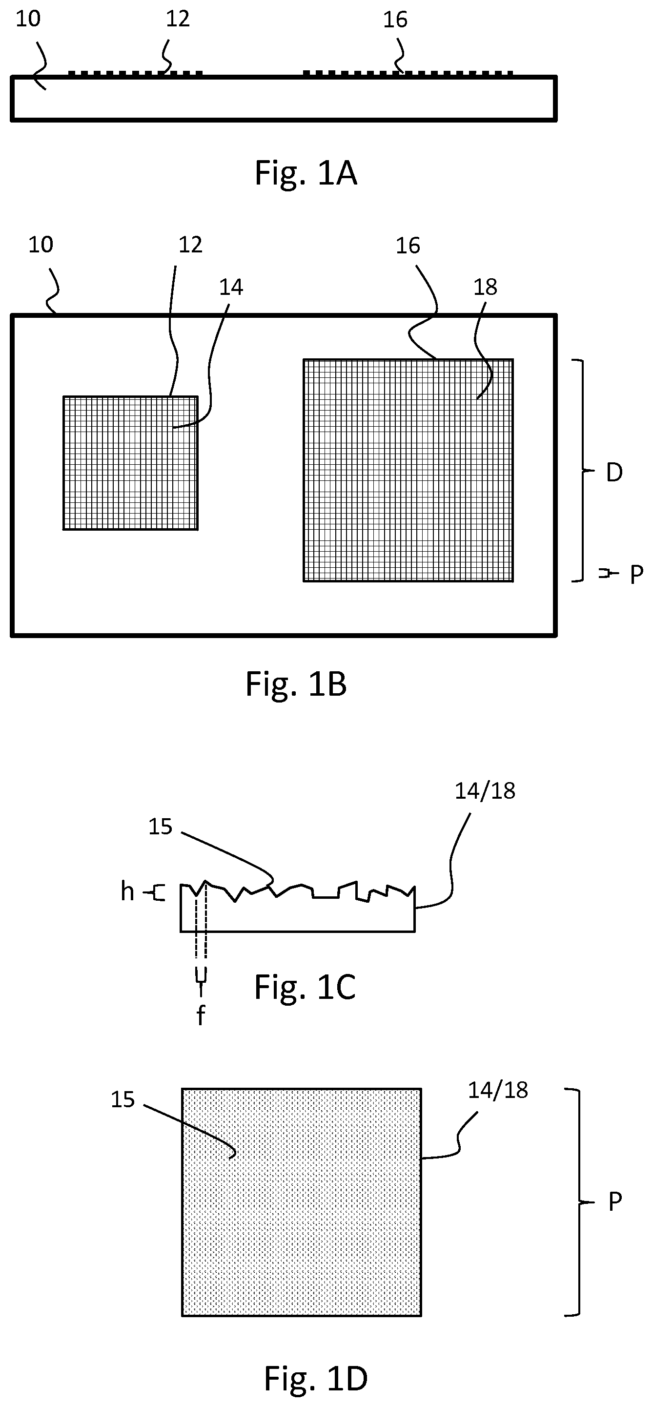
[0028] FIGS. 1A and 1B shows side and top views, respectively, of a display element with two two-dimensional large-period gratings arranged thereon.
[0029] FIGS. 1C and 1D show side and top views, respectively, of a microstructure of a single period of a large-period grating.
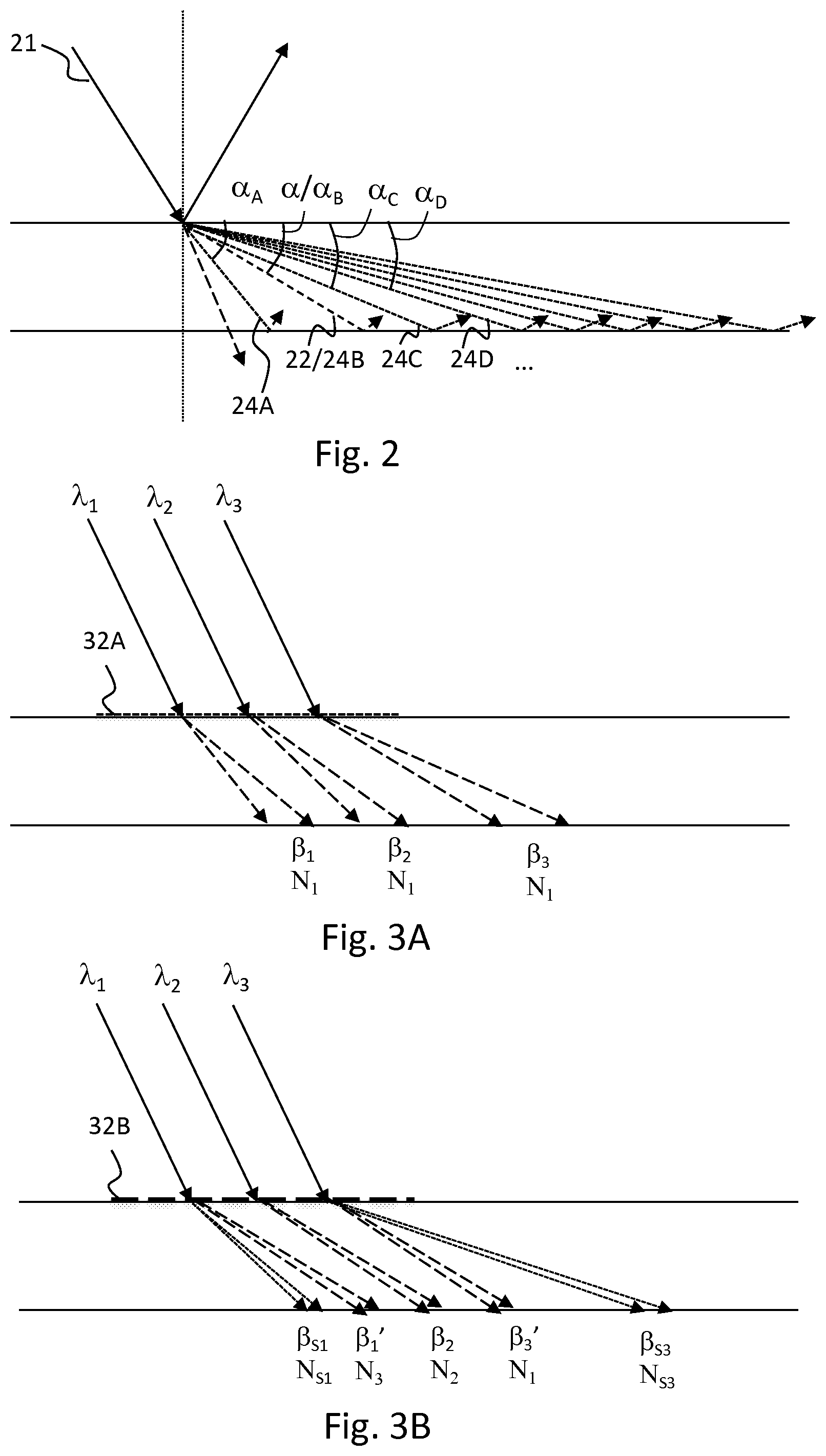
[0030] FIG. 2 illustrates the finer set of diffraction angles available in the invention.
[0031] FIGS. 3A and 3B illustrate the behavior of different wavelength bands on a conventional grating and a large-period grating according to one embodiment of the invention, correspondingly.
DETAILED DESCRIPTION OF EMBODIMENTS
[0032] Definitions
[0033] "(Grating) unit element" refers to the largest non-periodic unit that repeats inside the grating in one or two dimensions. The dimension, or two lateral dimensions, of the grating unit determines the period or periods, respectively, of the grating.
[0034] "Feature" refers to a geometric formation inside the unit element.
[0035] Unless otherwise mentioned, the term "wavelength band" herein means a band having a width of 20 nm or less, in particular 10 nm or less. In an RGB element or display, these wavelength bands can be chosen for example from the wavelength ranges of 600-750 nm, 495-600 nm and 450-495 nm, correspondingly. The number of bands can also be more than 3, such as 4-6.
[0036] "Achromatic" grating herein means a grating which, generates approximately the same response (i.e. approximately the same angular intensity distribution) for different wavelengths for a fixed incident angle and intensity. Herein, "approximately the same response" means that the relative intensity distribution is within -/+10% for all wavelengths going to the same angle (with an angular accuracy of 5 degrees, in particular 2 degrees). Relative intensity is determined as the proportion of intensity of light diffracted to a particular angle to the intensity of the incident light.
[0037] While it is possible to manufacture essentially entirely achromatic gratings using the presently disclosed principles for operating ranges that constitute only a limited number of narrow wavelength ranges. However, herein the term has a wider meaning and covers gratings satisfying the abovementioned condition. In practical applications, it is often sufficient that the achromatic condition is satisfied for the extreme angles of incidence of incoming light that are used in the device concerned. Between the extreme angles, the distributions of the rays with different wavelengths may overlap more freely.
[0038] Waveguide display devices and elements as herein used refer to devices and elements of producing a viewable image at least substantially maintaining relative pixel positions of an image to be displayed.
[0039] Description of Selected Embodiments
[0040] FIGS. 1A and 1B show an exemplary waveguide element in a cross-sectional side view and top view. The element comprises an in-coupling grating 12 and an out-coupling grating 16 laterally positioned with respect to each other on a waveguide body 10. The gratings 12, 16 are composed of repeating unit elements 14, 18, which have a side length P, corresponding to the period of the gratings 12, 16. The dimensions of the gratings as a whole (like dimension D of the out-coupling grating 16) can be e.g. 100-10000 times the period P, depending on the application.
[0041] In some embodiments, the grating is a one-dimensional grating, in which case a suitable period range is 5-1000 .mu.m, such as 10-500 .mu.m.
[0042] In some embodiments, the grating is a two-dimensional grating, whereby its period in each periodic direction can be e.g. 5-75 .mu.m, such as 10-50 .mu.m.
[0043] The element may also comprise guide gratings, exit pupil expander gratings or the like.
[0044] The unit elements 14, 18 of different gratings may be similar or different. The period is, however, in typical embodiments the same.
[0045] FIGS. 10 and 1D show an exemplary unit element in cross-sectional side view and top view. The unit element has a surface profile 15, which is essentially non-periodic, in order not to decrease the effective period of the grating. The structure is composed of microfeatures, which have the average size f and maximum height of h. Herein, f is defined as the average distance from the bottom of a valley to the top of the neighboring peak.
[0046] The feature size f can be e.g. 10-700 nm and maximum height h e.g. 20-500 nm.
[0047] FIG. 2 illustrates the finer diffraction angle division. Whereas a conventional small-period grating is capable of producing effectively only a single propagating diffraction order beam 22 at angle .alpha. for incident light 21, the present grating can diffract beams 24A, 24B, 24C, 24D, . . . in several propagating diffraction orders at angles .alpha..sub.A, .alpha..sub.B, .alpha..sub.C, .alpha..sub.D. . . .
[0048] FIGS. 3A and 3B illustrate how the finer angle division and design of the grating unit can be taken advantage of to produce a wavelength-dependent and incident angle-dependent division of diffraction efficiencies to different angles. In this example, an achromatic grating is illustrated.
[0049] FIG. 3A shows how three wavelength bands at .lamda..sub.1, .lamda..sub.2, .lamda..sub.3 having the same incident angle behave at a conventional grating 32A. One sees dispersive diffraction into the first propagating diffraction order N.sub.1 to angles .beta..sub.1, .beta..sub.2, .beta..sub.3, respectively, the amount of dispersion depending on the breadth of the bands.
[0050] In FIG. 3B, the grating is replaced with a large-period grating 32B, which is configured to diffract majority of light at band .lamda..sub.1 to diffraction order N.sub.3, at band .lamda..sub.2 to diffraction order N.sub.2 and at band .lamda..sub.3 to diffraction order N.sub.1, which all have essentially the same angle, i.e. .beta..sub.1'=.beta..sub.2=.beta..sub.3'. Stray light of band .lamda..sub.1 and band .lamda..sub.3 goes to stray diffraction orders N.sub.S1 , and N.sub.S3 having an angle .beta..sub.S1 and .beta..sub.S3different from .beta..sub.1'=.beta..sub.2=.beta..sub.3'. The grating can be configured to do the same for a plurality of incident angles. It must be noted that in the FIG. 3B only some stray diffraction orders have been illustrated, but in practice a small (controlled) amount of light is inevitably diffracted to all available orders.
[0051] In one embodiment, different incident angle ranges are diffracted into different diffraction orders.
[0052] Thus, the suggested grating structure/configuration can be used to "compress"/"decompress" the angular range of the diffracted light into a smaller/larger range, which can be used to increase the FOV of the element.
[0053] In typical embodiments, the majority of energy of incoming light is guided to a set of diffraction orders (primary diffraction orders) that is smaller than the set of all available diffraction orders. The remaining orders (secondary diffraction orders) may be used to carry stray light, as determined in grating optimization, in order to maximize the power to the primary diffraction orders or to satisfy other design targets. The number of primary diffraction orders can be e.g. 10 or less, such as 5 or less.
[0054] When inspected in the normalized wave vector space (k-space with lengths divided by k) of the light field, a conventional grating introduces a linear shift, whose direction and magnitude depends on the diffraction order, but not on the wavelength. In contrast to that, the present grating can induce non-linear shifts, which may be utilized to achieve for example compression/decompression of the angular spread and essentially achromatic behaviour for across small sets of narrow wavelength-bands.
[0055] In one embodiment, the present method comprises [0056] choosing a waveguide having a thickness and material, [0057] choosing one or more grating regions on the waveguide, [0058] choosing at least one optical performance target of the waveguide for light diffracting via said one or more grating regions, [0059] providing a grating model having as a variable at least one of the following: period of the grating and microstructure of the grating unit, [0060] keeping the period of the grating above 5 .mu.m, optimizing the at least one variable of the grating model so that the grating satisfied said optical performance target when placed on said one or more grating regions.
[0061] In a further embodiment, the at least one performance target comprises the diffraction of at least three separate wavelength bands, such as red, green and blue bands, having the same angle of incidence essentially to the same angle using different diffraction orders for each band. In a further embodiment, the at least one performance target comprises this condition to hold for several different angles of incidence, such as for at least 100 angles of incidence.
[0062] In a further embodiment, the method comprises manufacturing the waveguide having said grating on said one or more grating regions.
[0063] The detailed, sub-micrometer scale, structure of the present grating depends on the performance target and leans on the principle of using a great number of diffraction orders (in particular .gtoreq.10) as targets of light. In one embodiment, the diffraction to secondary diffraction orders is not forced to zero, but is allowed to carry a portion of light in order to increase the freedoms of design to achieve the performance target. In general, to optimize the structure, one can for example apply optimization strategies and ideas, such as the above one of not forcing secondary diffraction orders to zero, that are known from the design of so-called computer-generated holograms (CGHs). For the grating computations we recommend the use of recently developed publicly available fast methods, such as those discussed in A. Shcherbakov and A. V. Tishchenko, "New fast and memory-sparing method for rigorous electromagnetic analysis of 2D periodic dielectric structures", J. Quant. Spectrosc. Ra., 113, 158-171, 2012 and A. Junker and K.-H. Brenner, "High mode count rigorous simulation of diffractive optical elements by an iterative solution approach", EOS Topical Meeting on Diffractive Optics 2017, p. 23, to obtain realistic computation times.
[0064] Embodiments of the invention can be utilized in various personal display devices, augmented reality (AR), virtual reality (VR) and mixed reality (MR) devices, like near-to-the-eye displays (NEDs) and other head-mounted displays (HMDs), as well as head-up displays (HUDs), in their different forms.
CITATIONS LIST
Non-patent literature
[0065] Han J. et al, "Portable waveguide display system with a large field of view by integrating freeform elements and volume holograms", Optics Express. 23. 3534. 10.1364/OE.23.003534
[0066] A. Shcherbakov and A. V. Tishchenko, "New fast and memory-sparing method for rigorous electromagnetic analysis of 2D periodic dielectric structures", J. Quant. Spectrosc. Ra., 113, 158-171, 2012
[0067] A. Junker and K.-H. Brenner, "High mode count rigorous simulation of diffractive optical elements by an iterative solution approach", EOS Topical Meeting on Diffractive Optics 2017, p. 23
* * * * *
D00000
D00001
D00002
XML
uspto.report is an independent third-party trademark research tool that is not affiliated, endorsed, or sponsored by the United States Patent and Trademark Office (USPTO) or any other governmental organization. The information provided by uspto.report is based on publicly available data at the time of writing and is intended for informational purposes only.
While we strive to provide accurate and up-to-date information, we do not guarantee the accuracy, completeness, reliability, or suitability of the information displayed on this site. The use of this site is at your own risk. Any reliance you place on such information is therefore strictly at your own risk.
All official trademark data, including owner information, should be verified by visiting the official USPTO website at www.uspto.gov. This site is not intended to replace professional legal advice and should not be used as a substitute for consulting with a legal professional who is knowledgeable about trademark law.