Ascertaining the Pose of an X-Ray Unit Relative to an Object on the Basis of a Digital Model of the Object
Albarqouni; Shadi ; et al.
U.S. patent application number 16/497092 was filed with the patent office on 2020-12-03 for ascertaining the pose of an x-ray unit relative to an object on the basis of a digital model of the object. This patent application is currently assigned to Siemens Aktiengesellschaft. The applicant listed for this patent is Siemens Aktiengesellschaft. Invention is credited to Shadi Albarqouni, Linda Mai Bui, Slobodan Ilic, Michael Schrapp.
| Application Number | 20200378904 16/497092 |
| Document ID | / |
| Family ID | 1000005037748 |
| Filed Date | 2020-12-03 |


View All Diagrams
| United States Patent Application | 20200378904 |
| Kind Code | A1 |
| Albarqouni; Shadi ; et al. | December 3, 2020 |
Ascertaining the Pose of an X-Ray Unit Relative to an Object on the Basis of a Digital Model of the Object
Abstract
Various embodiments include a method for facilitating tomographic reconstruction comprising: emitting an x-ray beam from an x-ray unit; ascertaining an attenuation of the x-ray beam during transmission through an object situated in a beam path of the x-ray beam; ascertaining structure data of the object based at least in part on the attenuation of the x-ray beam; and ascertaining a pose of the x-ray unit relative to the object using a digital model of the object and based at least in part on the attenuation of the x-ray beam.
| Inventors: | Albarqouni; Shadi; (Munchen, DE) ; Bui; Linda Mai; (Olching/Grasslfing, DE) ; Schrapp; Michael; (Munchen, DE) ; Ilic; Slobodan; (Munchen, DE) | ||||||||||
| Applicant: |
|
||||||||||
|---|---|---|---|---|---|---|---|---|---|---|---|
| Assignee: | Siemens Aktiengesellschaft Munchen DE |
||||||||||
| Family ID: | 1000005037748 | ||||||||||
| Appl. No.: | 16/497092 | ||||||||||
| Filed: | March 20, 2018 | ||||||||||
| PCT Filed: | March 20, 2018 | ||||||||||
| PCT NO: | PCT/EP2018/056949 | ||||||||||
| 371 Date: | September 24, 2019 |
| Current U.S. Class: | 1/1 |
| Current CPC Class: | G01N 23/046 20130101; G06N 3/08 20130101; G01B 15/025 20130101; G01N 2223/419 20130101; G01N 2223/04 20130101; G06N 3/04 20130101; G01N 23/083 20130101; G01N 2223/401 20130101 |
| International Class: | G01N 23/046 20060101 G01N023/046; G01N 23/083 20060101 G01N023/083; G01B 15/02 20060101 G01B015/02; G06N 3/08 20060101 G06N003/08; G06N 3/04 20060101 G06N003/04 |
Foreign Application Data
| Date | Code | Application Number |
|---|---|---|
| Mar 27, 2017 | DE | 10 2017 205 113.2 |
Claims
1. A method for facilitating tomographic reconstruction, the method comprising: emitting an x-ray beam from an x-ray unit; ascertaining an attenuation of the x-ray beam during transmission through an object situated in a beam path of the x-ray beam; ascertaining structure data of the object based at least in part on the attenuation of the x-ray beam; and ascertaining a pose of the x-ray unit relative to the object using a digital model of the object and based at least in part on the attenuation of the x-ray beam.
2. The method as claimed in claim 1, wherein the x-ray unit comprises an x-ray source and an x-ray detector.
3. The method as claimed in claim 1, further comprising calculating model values for the attenuation of the x-ray beam during transmission through the object using the digital model of the object for a plurality of poses of the x-ray unit relative to the object.
4. The method as claimed in claim 3, wherein a device for machine learning is trained to ascertain the pose of the x-ray unit relative to the object using the ascertained attenuation of the x-ray beam using the model values.
5. The method as claimed in claim 3, wherein ascertaining the pose of the x-ray unit relative to the object includes comparing the ascertained attenuation of the x-ray beam to the model values.
6. The method as claimed in claim 5, wherein the device is further trained by backpropagation.
7. The method as claimed in claim 1, further comprising calculating projection values for the attenuation of the x-ray beam for the ascertained pose of the x-ray unit relative to the object; and comparing the projection values to the ascertained attenuation of the x-ray beam.
8. The method as claimed in claim 7, wherein the calculation of the projection values and/or ascertainment of the pose of the x-ray unit relative to the object by backpropagation is further trained on the basis of the comparison of the projection values with the ascertained attenuation.
9. An x-ray apparatus, comprising: an x-ray source for emitting an x-ray beam along a beam path; an x-ray detector for ascertaining an attenuation of the x-ray beam through an object situated in the beam path; a computing unit; and a memory unit storing a digital model of the object; wherein the computing unit executes a program containing instructions to ascertain a pose of the x-ray unit relative to the object based at least in part on the detected attenuation of the x-ray beam using the digital model.
10. The x-ray apparatus as claimed in claim 9, wherein the computing unit comprises an artificial neural network.
Description
CROSS-REFERENCE TO RELATED APPLICATIONS
[0001] This application is a U.S. National Stage Application of International Application No. PCT/EP2018/056949 filed Mar. 20, 2018, which designates the United States of America, and claims priority to DE Application No. 10 2017 205 113.2 filed Mar. 27, 2017, the contents of which are hereby incorporated by reference in their entirety.
TECHNICAL FIELD
[0002] The present disclosure relates to x-ray machines. Various embodiments may include methods for facilitating tomographic reconstruction of an object by means of an x-ray apparatus and/or x-ray apparatus.
BACKGROUND
[0003] X-ray apparatuses are used for diagnostics and testing as they can provide information about the inner structure of an object. X-ray images represent an attenuation of an x-ray beam caused by passing through an object. Typically, an x-ray beam is emitted by an x-ray source and detected by an x-ray detector. The attenuation is measured along the x-ray beam and depends both on the object and on the configuration of the x-ray apparatus. The configuration of the x-ray apparatus may relate to the precise distance between the x-ray source and the x-ray detector and the precise distance of the object from the x-ray source and from the x-ray detector. An accurate 3-D reconstruction can be achieved via tomographic reconstruction methods; a large number of x-ray images from different positions and angles and a precise configuration of the x-ray apparatus may be required to this end.
[0004] The precise configuration of the x-ray apparatus is achieved by the geometric reconstruction and geometric calibration of the x-ray apparatus. Mobile x-ray systems are frequently used in industrial applications. In this case, both the positions of the x-ray source and of the x-ray detector and the object to be inspected are as desired. Therefore, no precise configuration of the x-ray apparatus is provided in this case.
[0005] By way of example, C-arms for medical applications are known from the prior art. Here, inaccuracies in the configuration of the x-ray apparatus may lead to poor image quality of tomographically reconstructed images. The use of a calibration body for calibration purposes and the use of self-calibrating methods are known solutions to this problem. The calibration body is configured in such a way that its x-ray image is unambiguously identifiable, and position and orientation of the x-ray source and of the x-ray detector are unambiguously ascertainable therefrom. Methods for self-calibration envisage an analysis of the x-ray images. By way of example, the tomographically reconstructed image is estimated and geometric parameters are iteratively optimized in order to obtain an optimal reconstructed image.
SUMMARY
[0006] The teachings of the present disclosure may facilitate improved tomographic reconstruction of an object. For example, some embodiments include a method for facilitating tomographic reconstruction, including the steps of: emitting an x-ray beam (5) by an x-ray unit (1), ascertaining an attenuation of the x-ray beam (5) during transmission through the object (4) situated in a beam path of the x-ray beam (5) of the x-ray unit (1), ascertaining structure data of the object (4) on the basis of the attenuation of the x-ray beam (5), characterized in that a pose of the x-ray unit (1) is ascertained relative to the object (4) on the basis of a digital model of the object (4) and on the basis of the attenuation of the x-ray beam (5), for the purposes of facilitating the tomographic reconstruction.
[0007] In some embodiments, the x-ray unit (1) comprises an x-ray source (2) and an x-ray detector (3), wherein a relative position between x-ray source (2), object (4) and x-ray detector (3) is freely chosen provided the condition that the object (4) is situated in the beam path of the x-ray beam (5) is observed.
[0008] In some embodiments, model values (11) for the attenuation of the x-ray beam (5) during transmission through the object (4) are calculated on the basis of the digital model of the object (4) for a plurality of poses of the x-ray unit (5) relative to the object (4).
[0009] In some embodiments, a device (7) for machine learning, more particularly an artificial neural network, is trained to ascertain the pose of the x-ray unit (4) relative to the object (4) on the basis of the ascertained attenuation of the x-ray beam (5) using the model values (11).
[0010] In some embodiments, the pose of the x-ray unit (1) relative to the object (4) is ascertained at least in part by comparing the ascertained attenuation of the x-ray beam (5) to the model values (11).
[0011] In some embodiments, the device (7) for machine learning, more particularly the artificial neural network, is further trained by backpropagation (20).
[0012] In some embodiments, projection values for the attenuation of the x-ray beam (5) are calculated for the ascertained pose of the x-ray unit (1) relative to the object (4) and said projection values are compared to the ascertained attenuation of the x-ray beam (5).
[0013] In some embodiments, the calculation of the projection values and/or ascertainment of the pose of the x-ray unit (1) relative to the object (4) by backpropagation (21) is further trained on the basis of the comparison of the projection values with the ascertained attenuation.
[0014] As another example, some embodiments include an x-ray apparatus (9), comprising: an x-ray source (2) for emitting an x-ray beam (5), an x-ray detector (3) for ascertaining an attenuation of the x-ray beam (5) through an object (4) situated in the beam path of the x-ray beam (5), and comprising a computing unit (6) configured to ascertain structure data of the object (4) on the basis of the attenuation of the x-ray beam (5), characterized by a memory unit (8), in which a digital model of the object (4) is storable, wherein the computing unit (6) is configured to ascertain a pose of the x-ray unit (1) relative to the object (4) on the basis of the detected attenuation of the x-ray beam (5) and the digital model.
[0015] In some embodiments, the computing unit (6) comprises a device (7) for machine learning, more particularly an artificial neural network.
BRIEF DESCRIPTION OF THE DRAWINGS
[0016] Further features and advantages of the methods and systems described herein can be gathered from the following description on the basis of the appended figures. In the figures, the same reference signs denote the same features and functions. The exemplary embodiments only serve to explain the disclosure but not to restrict the scope.
[0017] In detail:
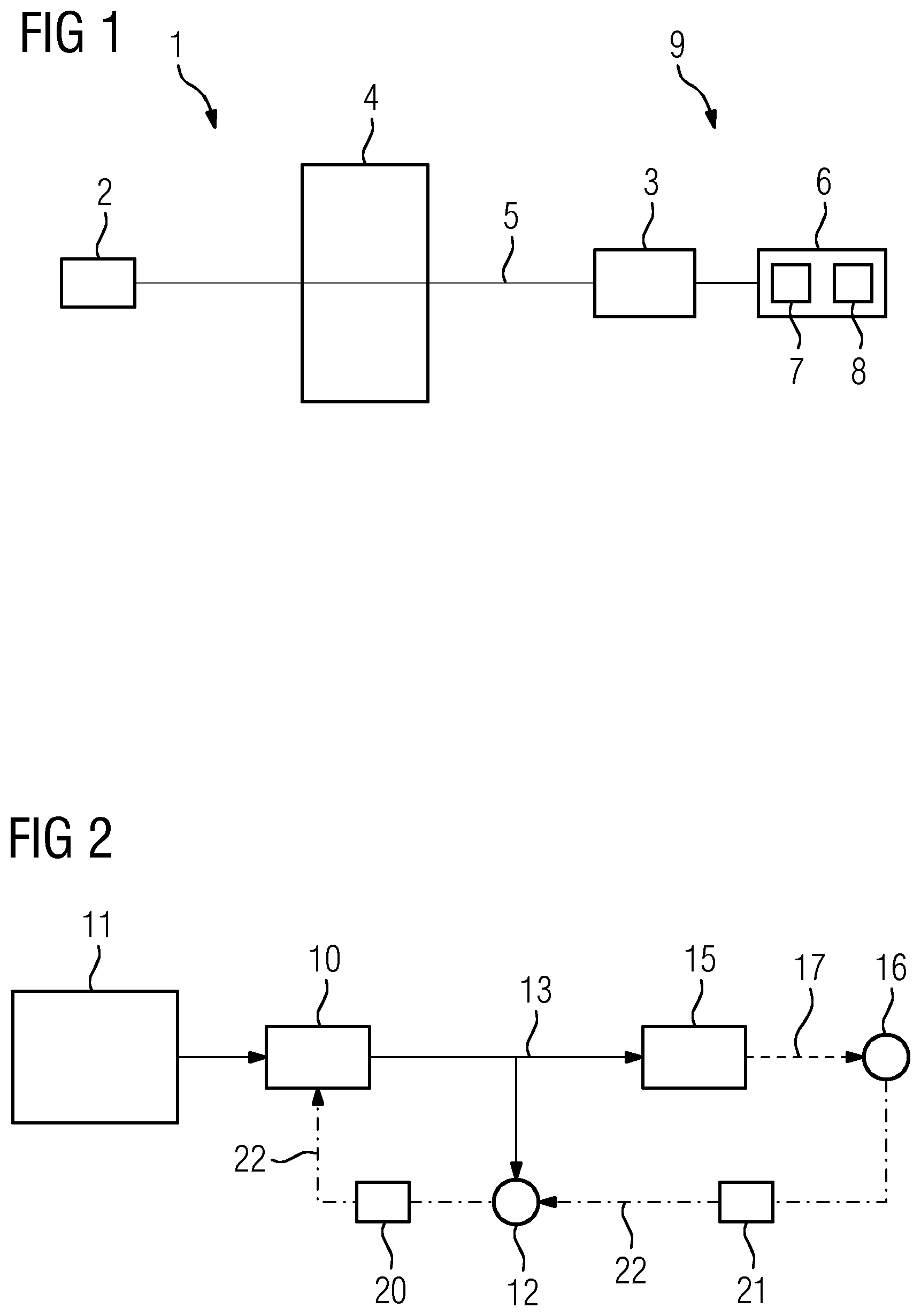
[0018] FIG. 1 shows a block diagram of an x-ray apparatus comprising an x-ray source and an x-ray detector; and
[0019] FIG. 2 shows a block diagram of an example embodiment of a method incorporating teachings of the present disclosure.
DETAILED DESCRIPTION
[0020] Initially, an x-ray beam is emitted by an x-ray unit in a generic method for facilitating tomographic reconstruction of an object. The x-ray unit comprises, in particular, an x-ray detector and an x-ray source, the latter emitting the x-ray beam. In another step, an attenuation of the x-ray beam during transmission through the object situated in a beam path of the x-ray beam of the x-ray unit is ascertained. The attenuation of the x-ray beam is ascertained by the x-ray detector.
[0021] In some embodiments, the x-ray detector records a two-dimensional x-ray image, wherein parts of the x-ray image, more particularly picture elements or pixels, are illuminated at an intensity that depends on the attenuation of the x-ray beam. Consequently, the attenuation of the x-ray beam can be ascertained in the form of the x-ray image. In some embodiments, the attenuation can be ascertained by capturing a residual intensity of the x-ray beam after the transmission through the object. The x-ray image may correspond to a two-dimensional projection of the residual intensity of the x-ray beam in an image plane of the x-ray image after transmission through the object, more particularly through the three-dimensional object.
[0022] Structure data of the object are ascertained on the basis of the attenuation of the x-ray beam. In some embodiments, the material thickness, the material type and/or an absorption coefficient for the object can be ascertained on the basis of the attenuation.
[0023] In some embodiments, a pose of the x-ray unit may be ascertained relative to the object on the basis of a digital model of the object and on the basis of the attenuation of the x-ray beam, for the purposes of facilitating the tomographic reconstruction. In particular, the attenuation of the x-ray beam is related to the digital model in order to ascertain the pose of the x-ray unit relative to the object. In this disclosure, "pose" means a combination of relative position and alignment.
[0024] In some embodiments, the pose of the object is ascertained relative to the x-ray detector and/or to the x-ray source. As an alternative or in addition thereto, the pose of the object can be ascertained relative to the x-ray unit. Improved tomographic reconstruction of the object is facilitated as a result of the pose of the x-ray unit being ascertained by means of the present methods.
[0025] The pose of the x-ray unit relative to the object is tantamount to the pose of the object relative to the x-ray unit. Consequently, within the scope of the present disclosure, the pose of the object relative to the x-ray detector should always be understood to also conversely mean the pose of the x-ray detector or of part of the x-ray detector, more particularly the x-ray source or the x-ray detector, relative to the object.
[0026] In some embodiments, the x-ray unit comprises an x-ray source and an x-ray detector, wherein a relative position between x-ray source, object, and x-ray detector is freely chosen provided the condition that the object is situated in the beam path of the x-ray beam is observed. Expressed differently, there is no set relative position in which the x-ray detector and the x-ray source or x-ray detector, x-ray source and object must be situated. In particular, the position of the x-ray source can be chosen independently of the position of the x-ray detector and/or the position of the object.
[0027] In some embodiments, model values for the attenuation of the x-ray beam during transmission through the object may be calculated on the basis of the digital model of the object for a plurality of poses of the x-ray unit relative to the object. In some embodiments, model values for the attenuation of the x-ray beam are calculated on the basis of a physical model and/or within the scope of a simulation. In some embodiments, the model values are calculated for a multiplicity of poses of the x-ray unit, more particularly the x-ray source, on a model-like sphere. The model values may form a basis for the ascertainment of the pose of the x-ray source relative to the object.
[0028] In some embodiments, there is a device for machine learning, e.g. an artificial neural network, to be trained to ascertain the pose of the x-ray unit relative to the object on the basis of the ascertained attenuation of the x-ray beam using the model values. In some embodiments, the device for machine learning is a convolutional neural network. Consequently, the model values can form training data to train the device for machine learning. On the basis of the model values, the device for machine learning can learn or recognize laws, relationships, or connections between the pose of the x-ray unit relative to the object and the attenuation of the x-ray beam.
[0029] In some embodiments, the pose of the x-ray unit relative to the object may be ascertained at least in part by comparing the ascertained attenuation of the x-ray beam to the model values. By way of example, the pose of the x-ray unit relative to the object is ascertained by virtue of the pose of the x-ray unit relative to the object, whose model values for the attenuation have the smallest deviation from the ascertained attenuation, being ascertained from the poses for which model values were calculated. Expressed differently, from the poses for which the model values were calculated, it is possible to select that pose whose model values for the attenuation have the smallest deviation from the ascertained attenuation. In some embodiments, there can be an extrapolation on the basis of the model values and on the basis of the poses for which model values were calculated in order to determine the pose of the x-ray unit relative to the object even more precisely.
[0030] In some embodiments, the device for machine learning may be further trained by backpropagation. In some embodiments, the backpropagation is carried out on the basis of the comparison of the model values with the ascertained attenuation of the x-ray beam. In some embodiments, it is possible to use data obtained by extrapolation on the basis of the model values to extend the model values. In this way, it is possible to improve the accuracy when ascertaining the pose of the x-ray unit relative to the object.
[0031] In some embodiments, projection values for the attenuation of the x-ray beam may be calculated for the ascertained pose of the x-ray unit relative to the object and for said projection values to be compared to the ascertained attenuation of the x-ray beam. In some embodiments, projection values for the attenuation of the x-ray beam are calculated on the basis of the digital model of the object and on the basis of the ascertained pose. The projection values can be calculated according to the same prescription as the model values. In some embodiments, the projection values are calculated in the form of a projection image, wherein the projection image corresponds in particular to a simulation for an x-ray image. The projection image can be compared to the x-ray image recorded by the x-ray detector. The quality of the ascertainment of the pose of the x-ray unit relative to the object can be deduced depending on the degree of correspondence between the projection image and x-ray image. The quality of the ascertainment of the pose of the x-ray unit relative to the object can be considered to be better with improved correspondence between the projection image and the x-ray image.
[0032] In some embodiments, there is a two-stage method, in which, initially, the pose of the x-ray unit is ascertained relative to the object on the basis of the model values for the attenuation of the x-ray beam and the ascertained attenuation of the x-ray beam. Subsequently, the projection values for the attenuation are calculated on the basis of the ascertained pose of the x-ray unit relative to the object and said projection values are compared to the ascertained attenuation of the x-ray beam. Consequently, there is two-stage verification for the pose of the x-ray unit relative to the object.
[0033] In some embodiments, the calculation of the projection values and/or ascertainment of the pose of the x-ray unit relative to the object by backpropagation may be further trained on the basis of the comparison of the projection values with the ascertained attenuation. In some embodiments, calculation prescriptions for calculating the projection values and/or calculation prescriptions for ascertaining the pose of the x-ray unit relative to the object are fitted in such a way that a deviation that is as small as possible, or a minimal achievable deviation, is attained between the projection values for the attenuation of the x-ray beam and the ascertained attenuation of the x-ray beam. In some embodiments, errors when ascertaining the pose of the x-ray unit are reduced by the two-stage method.
[0034] In some embodiments, there is an x-ray apparatus comprising an x-ray source for emitting an x-ray beam and an x-ray detector for ascertaining an attenuation of the x-ray beam by an object situated in the beam path of the x-ray beam. Moreover, the x-ray apparatus comprises a computing unit configured to ascertain structure data of the object on the basis of the attenuation of the x-ray beam.
[0035] In some embodiments, the x-ray apparatus comprises a memory unit, in which a digital model of the object is storable. Moreover, the computing unit may be configured to ascertain a pose of the x-ray unit relative to the object on the basis of the detected attenuation of the x-ray beam and the digital model. In some embodiments, the digital model of the object is stored in the memory unit. In some embodiments, the digital model of the object is stored in the memory unit when tomographic reconstruction of the object 4 is to take place. In some embodiments, the computing unit comprises a device for machine learning, more particularly an artificial neural network.
[0036] FIG. 1 shows an x-ray apparatus 9 comprising an x-ray unit 1. The x-ray unit 1 comprises an x-ray source 2 and an x-ray detector 3. The x-ray source 2 emits an x-ray beam 5 in the direction of the x-ray detector 3. In some embodiments, the x-ray source 2 is an x-ray tube with a copper anode. The object 4 is situated in a beam path of the x-ray beam 5. In some embodiments, the object 4 is a test object. In some embodiments, a tomographic image of the object 4 is to be created for testing the latter.
[0037] Individual parts of the x-ray unit 1, more particularly the x-ray source 2 and the x-ray detector 3, can be movable on their own. In some embodiments, the position of the x-ray source 2 and/or of the x-ray detector 3 can be freely chosen under the condition that the object 4 is situated in the beam path of the x-ray beam 5. Consequently, the x-ray unit 1 can be arranged freely around the object 4. By way of example, this allows testing of particularly large objects 4, for example a rotor for a wind turbine.
[0038] In some embodiments, the x-ray beam 5 is an electromagnetic wave at the predetermined wavelength. In some embodiments, x-ray photons of the x-ray beam 5 have an energy of between 5 keV and several 100 keV. The x-ray beam 5 can include monochromatic or polychromatic x-ray radiation.
[0039] The x-ray beam 5 is transmitted through the object 4. Expressed differently, the object 4 is passed by the x-ray beam 5. The x-ray beam 5 is attenuated during transmission through the object 4. The amplitude of the x-ray beam 5 is attenuated or reduced. By way of example, the amplitude of the x-ray beam 5 decreases exponentially during transmission through the object 4.
[0040] In some embodiments, the x-ray detector 3 comprises a photodiode, a CCD sensor or a photographic plate. The x-ray beam 5 is detected by the x-ray detector 3. In some embodiments, the x-ray detector 3 ascertains the attenuation of the x-ray beam 5 during the transmission through the object 4. In some embodiments, an x-ray image is recorded by the x-ray detector 3. The x-ray image may represent the attenuation of the x-ray beam in a detection plane of the x-ray detector. In some embodiments, the attenuation of the x-ray beam in the detection plane is represented by grayscales of the x-ray image.
[0041] The x-ray apparatus 9 may comprise a computing unit 6 for ascertaining structure data of the object 4. In some embodiments, structure data of the object 4 relate to a layer thickness, an amount of substance or a density passed by the x-ray beam 5. On account of the free mobility of the x-ray source 2 and the x-ray detector 3 in relation to one another, it is initially necessary to ascertain the pose of the x-ray unit 1, more particularly of the x-ray source 2 and/or of the x-ray detector 3, relative to the object 4 in order to facilitate tomographic reconstruction of the object 4. In some embodiments, the pose is the position and orientation of the x-ray unit 1 relative to the object 4. The pose of the x-ray unit 1, more particularly of the x-ray source 2 and/or of the x-ray detector 3, relative to the object 4 is tantamount to the pose of the object 4 relative to the x-ray unit 1, more particularly the x-ray source 2 and/or the x-ray detector 3.
[0042] In some embodiments, the computing unit 6 comprises a device 7 for machine learning and a memory unit 8. The computing unit 6 may comprise program memory for storing executable program code. In some embodiments, a digital image x of the object 4 is stored in the memory unit 8. In some embodiments, the object 4 has been produced on the basis of the digital image x. In some embodiments, the correct manufacture is to be tested on the basis of the tomographic reconstruction of the object 4. In some embodiments, the digital image x is a CAD model or a blueprint. The device 7 for machine learning can be embodied as an artificial neural network, more particularly as a "convolutional neural network".
[0043] A common optimization of calibration of the x-ray unit 1 and the tomographic reconstruction of the object 4 is a problem defined by few conditions. In industrial applications, the digital image x is often available for the object 4. In some embodiments, the digital image x is used as initial information. The use of the digital image x may be advantageous, particularly if the x-ray unit 1 has not been calibrated.
[0044] In some embodiments, model values 11 for the attenuation of the x-ray beam 5 are calculated for different poses of the x-ray unit 1, more particularly of the x-ray source 2, relative to the object 4 on the basis of the digital image x of the object 4. In some embodiments, model images are calculated, the model images being calculated x-ray images. Expressed differently, the model images of the object 4 can be calculated as model values 11 on the basis of the digital image x of the object 4. In some embodiments, a multiplicity of model values 11 are calculated for a multiplicity of model poses of the x-ray unit 1, more particularly of the x-ray source 2, relative to the object 4. In some embodiments, the model poses can be arranged around the object 4 in accordance with a sphere. In some embodiments, the x-ray unit 1 is arranged in such a way according to the model poses that the x-ray detector 3 always lies opposite the x-ray source 2 on the sphere.
[0045] The device 7 for machine learning is trained on the basis of the model values 11. In some embodiments, the device 7 for machine learning may comprise an ascertainment unit 10 for ascertaining the pose of the x-ray unit 1, more particularly of the x-ray source 2, relative to the object 4. The ascertainment unit 10 can be realized as program code, which, for example, is stored and/or executed in the computing unit 6 or the device 7 for machine learning. In some embodiments, the ascertainment unit 10 is trained on the basis of the model values 11.
[0046] The ascertainment unit 10 can be configured to learn and/or refine model parameters .omega. on the basis of the model values 11, which may serve as training data D for machine learning. In some embodiments, the ascertainment unit 10 comprises a "deep learning model" f( ). The deep learning model f( ) is trained or taught on the basis of the model values 11. In some embodiments, the model values 11 comprise a set of training data D={(b.sub.1,p.sub.1), . . . , (b.sub.n,p.sub.n)}. The training data D comprise pairs of model images b.sub.i and the model pose p.sub.i belonging to the model images. The model pose p.sub.i describes the pose of the x-ray unit 1, more particularly of the x-ray source 2, relative to the object 4, for which a respective model image b.sub.i is calculated.
[0047] The following applies to the model images: b.sub.i=vec(I.sub.Xray).di-elect cons..sup.m, where vec( ) describes a vectorization operator and m describes the dimension of the model image. The following applies to the model pose p.sub.i: p.sub.i.di-elect cons..sup.d, wherein the model pose p.sub.i may be a vector in d-dimensional space. In some embodiments, is the set of real numbers.
[0048] In some embodiments, the pose p is set by the orientation q and the position t of the x-ray source 2. In some embodiments, the orientation q is described in quaternions (q.sub.1,q.sub.2,q.sub.3,q.sub.4) and the position t is described in Cartesian coordinates (t.sub.x,t.sub.y,t.sub.z). Here, the quaternions (q.sub.1,q.sub.2,q.sub.3,q.sub.4) describe the three degrees of freedom of rotation in respect of the Cartesian coordinate axes (x, y, z).
[0049] In some embodiments, the orientation q can be described in Euler angles and/or the position t can be described in spherical coordinates. Overall, there are six degrees of freedom for the pose p (three in respect of translation; three in respect of rotation). Naturally, this analogously also applies to the model pose p.sub.i.
p=[q,t]=(q.sub.1,q.sub.2,q.sub.3,q.sub.4,t.sub.x,t.sub.y,t.sub.z)
[0050] The ascertainment unit 10 ascertains the pose {circumflex over (p)}, more particularly a pose vector, of the x-ray unit 1, more particularly of the x-ray source 2, on the basis of an x-ray image b captured by the x-ray unit 1. Expressed differently, the pose {circumflex over (p)} is ascertained by means of the deep learning model f( ) on the basis of the captured x-ray image b and the model parameters .omega.:
{circumflex over (p)}=f(b;.omega.)
[0051] The ascertained pose {circumflex over (p)} can subsequently be used for the tomographic reconstruction. The tomographic reconstruction can be expressed by the mathematical problem set forth below. In this case, A( ) is the projection operator, x is the digital image x of the object 4 and R( ) is a regularization term:
argmin x b - A ( p ^ ) x 2 + R ( x ) ##EQU00001##
[0052] An optimization function .sub.pose for ascertaining the pose is defined as follows:
L pose = t - t ^ 2 + .beta. q - q ^ q ^ 2 ##EQU00002##
[0053] The optimization function .sub.pose can be trained by means of the model values 11 that form the training data D. By way of example, the various pairs (b.sub.i,p.sub.i) of model images b.sub.i and model poses p.sub.i are inserted into the optimization function in this case. It should be noted in the formula above that the quaternions {circumflex over (q)} for the ascertained pose {circumflex over (p)} are normalized. The {circumflex over (t)} are the Cartesian coordinates of the ascertained pose {circumflex over (p)}. .beta. is a weighting factor for weighting the Cartesian coordinates and the quaternions. In FIG. 2, the optimization function .sub.pose is represented by a first point 12. After training the ascertainment unit 10, the same can ascertain the pose of the x-ray unit 1, more particularly of the x-ray source 2.
[0054] The model parameters .omega. of the deep learning model f( ) can be fitted by a first backpropagation 20. To this end, FIG. 2 provides a backpropagation path 22. In particular, the first backpropagation 20 is implemented by forming a gradient, preferably of the optimization function .sub.pose. In the present case, the model parameters .omega. are optimized by the first backpropagation 20 directly on the basis of the optimization function .sub.pose. By way of example, a minimum for the error when ascertaining the pose {circumflex over (p)} can be found by forming the gradient. In this way, the accuracy of the ascertainment of the pose {circumflex over (p)} can be increased by minimizing the error on the basis of known poses, more particularly the model poses p.sub.i:
.differential. L pose .differential. p ^ = [ .differential. L pose .differential. q ^ , .differential. L pose .differential. t ^ ] = ( .differential. .differential. q 1 ^ , , .differential. .differential. t x ^ , ) ##EQU00003##
[0055] Additionally, a projector 15 may be provided to further improve the accuracy when ascertaining the pose of the x-ray unit 1, more particularly of the x-ray source 2. The more accurately the pose of the x-ray unit 1, more particularly of the x-ray source 2, is ascertained, the more accurately the tomographic reconstruction of the object 4 can be implemented.
[0056] The projector 15 can be part of the device 7 for machine learning. The projector 15 can be realized as program code which, for example, is stored and/or executed in the computing unit 6 or in the device 7 for machine learning. By way of the projector 15, it is possible to calculate projection values for the attenuation of the x-ray beam 5 by the object 4 from the ascertained pose {circumflex over (p)} and the digital image x of the object 4. In particular, a projection image {circumflex over (b)} is calculated, the projection image {circumflex over (b)} corresponding to an x-ray image that is calculated for the x-ray unit 1, more particularly the x-ray source 2, in the ascertained pose {circumflex over (p)} on the basis of the digital image x of the object 4.
{circumflex over (b)}=A({circumflex over (p)})x
[0057] The optimization function .sub.pose can be constricted by defining a projection error .sub.recon. In FIG. 2, the projection error .sub.recon is represented by a second circle 16. By way of example, the optimization function .sub.pose can be optimized with the minimization of the projection error .sub.recon as a constraint. In the present case, there is the constraining assumption that the projection error .sub.recon does not exceed a predetermined limit value (s.t. is an abbreviation for "subject to"):
argmin t ^ , q ^ t - t ^ 2 + .beta. q - q ^ q ^ 2 , s . t . b - b ^ 2 .ltoreq. ##EQU00004##
[0058] Expressed differently, the projection image {circumflex over (b)} for the ascertained pose {circumflex over (p)} and the actual image b may deviate from one another by no more than the predetermined limit value . Depending on operating mode or learning mode, the actual image b can The optimization function .sub.pose with the constraint relating to the projection error .sub.recon can be converted into an optimization problem without constraint by means of a Lagrange multiplier .lamda.:
argmin t ^ , q ^ t - t ^ 2 + .beta. q - q ^ q ^ 2 + .lamda. b - b ^ 2 ##EQU00005##
[0059] where
L pose = t - t ^ 2 + .beta. q - q ^ q ^ 2 ##EQU00006## L recon = .lamda. b - b ^ 2 ##EQU00006.2##
[0060] The first backpropagation 20 can be replaced or expanded by a second backpropagation 21. In particular, the model parameters .omega. are fitted or trained both by means of the first backpropagation 20 and by means of the second backpropagation 21. Consequently, the deep learning model f( ) can be fitted or trained both on the basis of the gradient of the optimization function .sub.pose and on the basis of a gradient of the projection error .sub.recon. The second backpropagation 21 can be implemented by means of the following gradients:
.differential. L .differential. p ^ = .differential. L pose .differential. p ^ + .lamda. .differential. L recon .differential. p ^ ##EQU00007##
[0061] The following term emerges on account of the chain rule:
.differential. L recon .differential. p ^ = .differential. L recon .differential. b ^ .differential. A ( p ^ ) x .differential. p ^ ##EQU00008##
[0062] On account of the type of the projection operator A( ), it is not possible to analytically determine the gradient of the projection error .sub.recon in relation to the pose. Therefore, the gradient is numerically approximated individually for each parameter by way of a differential calculation. By way of example, the partial derivative of the Cartesian coordinates {circumflex over (t)} along the z-axis can be calculated as follows, where h describes a small, constant number that approaches :
.differential. A ( p ^ ) .differential. t z ^ = lim h .fwdarw. A ( ( , t z ^ + h ) ) - A ( ( , t z ^ - h ) ) 2 h ##EQU00009##
[0063] Lastly, the basics of the teachings of the present disclosure may be summarized: knowledge of the exact pose of the x-ray unit 1, more particularly of the x-ray source 2, relative to the object 4 allows the tomographic reconstruction of the object 4. Since the individual parts of the x-ray unit 1, more particularly the x-ray source 2 and the x-ray detector 3, are freely movable and freely positioned in relation to the object 4, determining the pose facilitates the tomographic reconstruction. To this end, model values 11 may be calculated on the basis of a digital image x of the object 4, wherein the model values 11 comprise simulated x-ray images for a plurality of model poses p.sub.i of the x-ray unit 1, more particularly of the x-ray source 2. The model values 11 serve as training data D for training the device 7 for machine learning. After training the device 7 for machine learning, the same is able, in a first path 13, to ascertain the pose of the x-ray unit 1, more particularly of the x-ray source 2, on the basis of an x-ray image of the x-ray unit 1.
[0064] For the purposes of verifying the ascertained pose {circumflex over (p)}, a projection image {circumflex over (b)} for the ascertained pose {circumflex over (p)} is calculated on the basis of the digital image x in a second path 17. The projection image {circumflex over (b)} is compared to the x-ray image b of the x-ray unit 1.
[0065] By way of a backpropagation path 22, the device 7 for machine learning can be adapted or further trained by way of a first backpropagation 20 and/or a second backpropagation 21. In some embodiments, the backpropagation is implemented on the basis of error minimization by forming gradients.
* * * * *
D00000
D00001
P00001
P00002

XML
uspto.report is an independent third-party trademark research tool that is not affiliated, endorsed, or sponsored by the United States Patent and Trademark Office (USPTO) or any other governmental organization. The information provided by uspto.report is based on publicly available data at the time of writing and is intended for informational purposes only.
While we strive to provide accurate and up-to-date information, we do not guarantee the accuracy, completeness, reliability, or suitability of the information displayed on this site. The use of this site is at your own risk. Any reliance you place on such information is therefore strictly at your own risk.
All official trademark data, including owner information, should be verified by visiting the official USPTO website at www.uspto.gov. This site is not intended to replace professional legal advice and should not be used as a substitute for consulting with a legal professional who is knowledgeable about trademark law.