Heat Dissipation Unit With Axial Capillary Structure
Liu; Han-Min
U.S. patent application number 16/452547 was filed with the patent office on 2020-12-03 for heat dissipation unit with axial capillary structure. The applicant listed for this patent is ASIA VITAL COMPONENTS (CHINA) CO., LTD.. Invention is credited to Han-Min Liu.
| Application Number | 20200378690 16/452547 |
| Document ID | / |
| Family ID | 1000004157230 |
| Filed Date | 2020-12-03 |


| United States Patent Application | 20200378690 |
| Kind Code | A1 |
| Liu; Han-Min | December 3, 2020 |
HEAT DISSIPATION UNIT WITH AXIAL CAPILLARY STRUCTURE
Abstract
A heat dissipation unit with axial capillary structure includes a case and at least one tubular body. The case has an internal case chamber and at least one opening in communication with the case chamber. A case capillary structure is formed in the case chamber. The tubular body has at least one axial capillary structure, an open end and a closed end. The open end and the closed end together define a tubular body chamber in communication with the open end. The axial capillary structure is disposed in the tubular body and the open end is plugged in the opening. The axial capillary structure directly abuts against and connects with the case capillary structure disposed on the bottom side of the case in the case. The heat dissipation unit with axial capillary structure is able to achieve better capillary transfer effect.
| Inventors: | Liu; Han-Min; (Shenzhen, CN) | ||||||||||
| Applicant: |
|
||||||||||
|---|---|---|---|---|---|---|---|---|---|---|---|
| Family ID: | 1000004157230 | ||||||||||
| Appl. No.: | 16/452547 | ||||||||||
| Filed: | June 26, 2019 |
| Current U.S. Class: | 1/1 |
| Current CPC Class: | F28D 15/04 20130101 |
| International Class: | F28D 15/04 20060101 F28D015/04 |
Foreign Application Data
| Date | Code | Application Number |
|---|---|---|
| May 27, 2019 | TW | 108118290 |
Claims
1. A heat dissipation unit comprising: a case defining a case chamber and an opening; a case capillary structure formed in the case chamber; a tubular body extending away from the case and with an open end and a closed end opposite to the open end, wherein the open end is connected and sealed to the case at the opening such that the tubular body defines a tubular body chamber in fluid communication with the case chamber; at least one elongate axial capillary structure arranged within the tubular body and extending along a longitudinal axis of the tubular body and abutting and connected to the case capillary structure; and a working fluid filled in the case chamber and the tubular body chamber.
2. The heat dissipation unit of claim 1, wherein the opening is formed at a central position of a side of the case.
3. The heat dissipation unit of claim 1, wherein the tubular body extends perpendicular to a major plane of the case.
4. The heat dissipation unit of claim 1, wherein the at least one axial capillary structure extends completely between the open and closed ends.
5. The heat dissipation unit of claim 1, wherein the at least one axial capillary structure is arranged on an inner surface of the tubular body.
6. The heat dissipation unit of claim 1, comprising a plurality of axial capillary structures spaced apart from each other.
7. The heat dissipation unit of claim 6, wherein the plurality of axial capillary structures are arranged about an inner surface of the tubular body.
8. The heat dissipation unit of claim 6, wherein the plurality of axial capillary structures are equally spaced apart from each other.
9. The heat dissipation unit of claim 6, further comprising a tubular body capillary structure arranged in the tubular body and contacting each axial capillary structure and the case capillary structure.
10. The heat dissipation unit of claim 9, wherein the tubular body capillary structure encloses each axial capillary structure.
11. The heat dissipation unit of claim 9, wherein the tubular body capillary structure and the axial capillary structures substantially fill the tubular body.
12. The heat dissipation unit of claim 1, further comprising a tubular body capillary structure arranged in the tubular body and contacting the at least one axial capillary structure and the case capillary structure.
13. The heat dissipation unit of claim 12, wherein the tubular body capillary structure contacts at least part of an inner surface of the tubular body.
Description
[0001] This application claims the priority benefit of Taiwan patent application number 108118290 filed on May 27, 2019.
BACKGROUND OF THE INVENTION
1. Field of the Invention
[0002] The present invention relates generally to a heat dissipation unit with axial capillary structure, and more particularly to a heat dissipation unit with axial capillary structure, which is able to achieve better capillary transfer effect.
2. Description of the Related Art
[0003] The operation speed of the electronic components has become higher and higher. As a result, the heat generated by the electronic components has become higher and higher. To solve the heat dissipation problem of the electronic components, heat pipes and vapor chambers with good heat conductivity are widely applied to the electronic components. The vapor working fluid in the heat pipe can flow in a unified direction. However, the heat pipe has a limited volume so that the heat conducted by the heat pipe is quite limited. Moreover, the vapor chamber has a wider heated area for directly attaching to a heat source to conduct the heat generated by the heat source. However, the vapor working fluid in the vapor chamber flows in quite random directions so that the heat conduction and dissipation performance of the vapor chamber is limited.
[0004] Some manufacturers combine the conventional vapor chamber and heat pipe. The heat pipe is uprightly disposed on the vapor chamber with the internal chambers of the heat pipe and the vapor chamber in communication with each other. In addition, a tubular wall capillary structure is disposed on the entire inner circumference of the chamber of the heat pipe. The capillary structure is formed of sintered powder body or woven mesh. A plate wall capillary structure formed of sintered powder body or woven mesh is also formed on the upper and lower inner walls of the chamber of the vapor chamber. The sintered powder body or the woven mesh of the tubular wall capillary structure on the inner circumference of the heat pipe defines multiple voids, which provide capillary attraction to suck the condensed working fluid and make the condensed working fluid flow back to the plate wall capillary structure on the upper and lower inner walls of the chamber of the vapor chamber. Accordingly, the vapor-liquid circulation can be continuously repeatedly performed to dissipate the heat. However, there is a problem in such structure. That is, after cooled, the cooled working fluid (the liquid working fluid) will be absorbed by the sintered powder body or the woven mesh of the tubular wall capillary structure on the inner circumference of the heat pipe under the capillary attraction of the multiple voids. As a result, the liquid working fluid will gradually randomly spread over the entire inner circumference of the heat pipe. Also, the liquid working fluid will gradually downward flow along the inner circumference of the heat pipe in random directions back to the plate wall capillary structure on the upper and lower inner walls of the chamber of the vapor chamber.
[0005] Therefore, the cooled liquid working fluid cannot quickly flow back to the vapor chamber so that the problem of dry burn may take place due to insufficiency of the working fluid. Accordingly, the tubular wall capillary structure formed of sintered powder body and/or woven mesh in the conventional heat pipe can only provide capillary attraction to slowly transfer the liquid working fluid. As a result, as a whole, the capillary transfer efficiency is poor and the heat dissipation effect is poor.
SUMMARY OF THE INVENTION
[0006] It is therefore a primary object of the present invention to provide a heat dissipation unit with axial capillary structure, which is able to achieve better capillary transfer effect and enhance the heat dissipation efficiency.
[0007] It is a further object of the present invention to provide the above heat dissipation unit with axial capillary structure, in which a case capillary structure is formed in a case and an axial capillary structure is disposed on the inner circumference of at least one tubular body. The axial capillary structure is connected with the case capillary structure. Under the axial capillary attraction of the axial capillary structures, a cooled working fluid (liquid working fluid) will quickly axially flow back into the case. Accordingly, the working fluid can more efficiently flow in axial direction to achieve better heat dissipation effect.
[0008] To achieve the above and other objects, the heat dissipation unit with axial capillary structure of the present invention includes a case and at least one tubular body. The case has a case chamber and at least one opening. A working fluid is filled in the case chamber. A case capillary structure is formed in the case chamber. The at least one opening is formed through a top side of the case in communication with the case chamber. The at least one tubular body has at least one axial capillary structure, an open end and a closed end opposite to the open end. The open end and the closed end together define a tubular body chamber. The open end is in communication with the tubular body chamber and the case chamber. The axial capillary structure is disposed in the tubular body and distributed in the longitudinal direction of the tubular body. The open end of the tubular body is plugged in the at least one opening. The axial capillary structure directly abuts against and connects with the case capillary structure disposed on the bottom side of the case in the case chamber. By means of the axial capillary structure of the heat dissipation unit, the working fluid can more efficiently flow in axial direction to achieve better capillary transfer effect and enhance the heat dissipation efficiency.
BRIEF DESCRIPTION OF THE DRAWINGS
[0009] The structure and the technical means adopted by the present invention to achieve the above and other objects can be best understood by referring to the following detailed description of the preferred embodiments and the accompanying drawings, wherein:
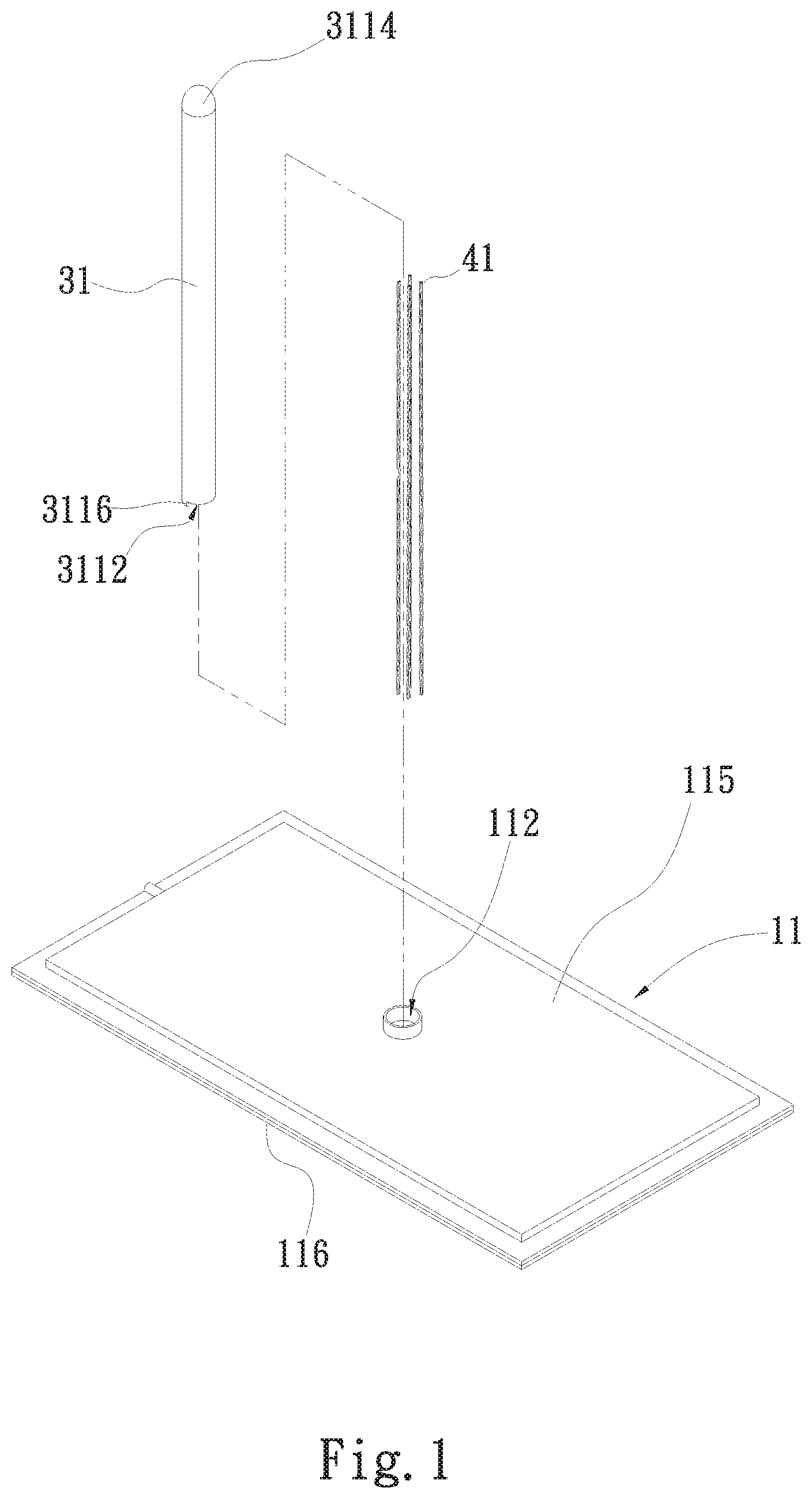
[0010] FIG. 1 is a perspective exploded view of a first embodiment of the present invention;
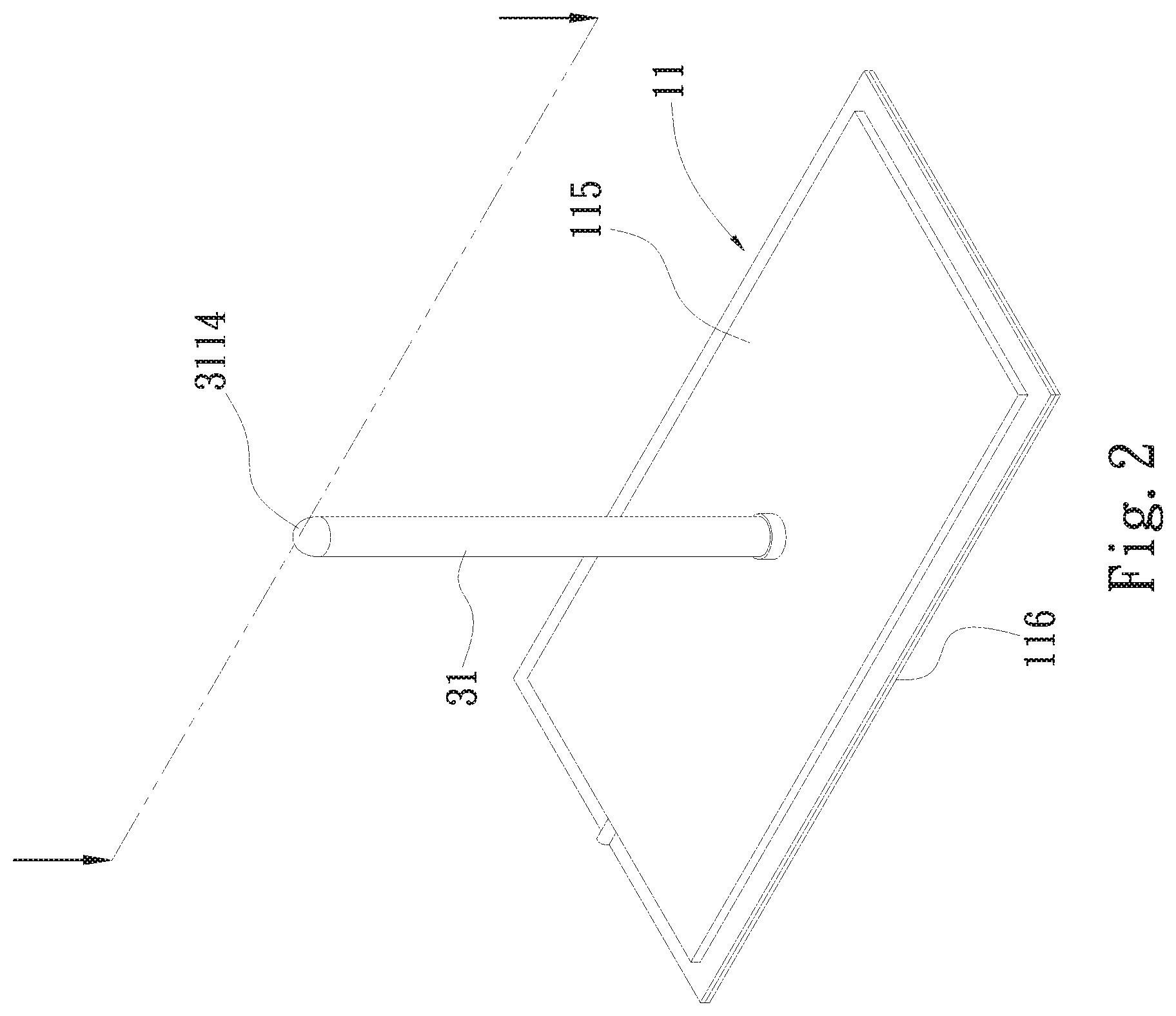
[0011] FIG. 2 is a perspective assembled view of the first embodiment of the present invention;
[0012] FIG. 2A is a sectional assembled view of the first embodiment of the present invention;
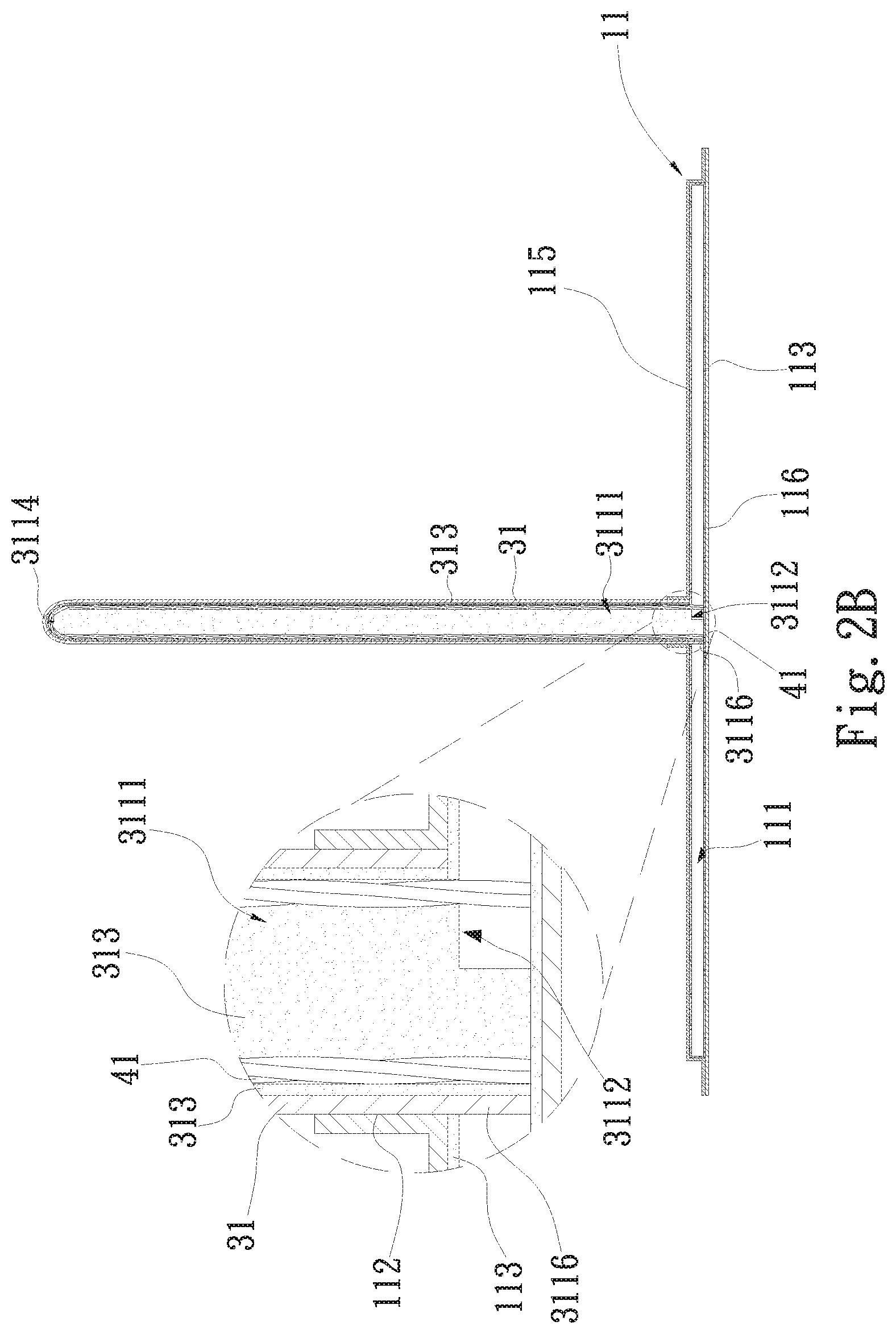
[0013] FIG. 2B is a sectional assembled view of a modified embodiment of the first embodiment of the present invention;
[0014] FIG. 2C is a sectional assembled view of a modified embodiment of the first embodiment of the present invention; and
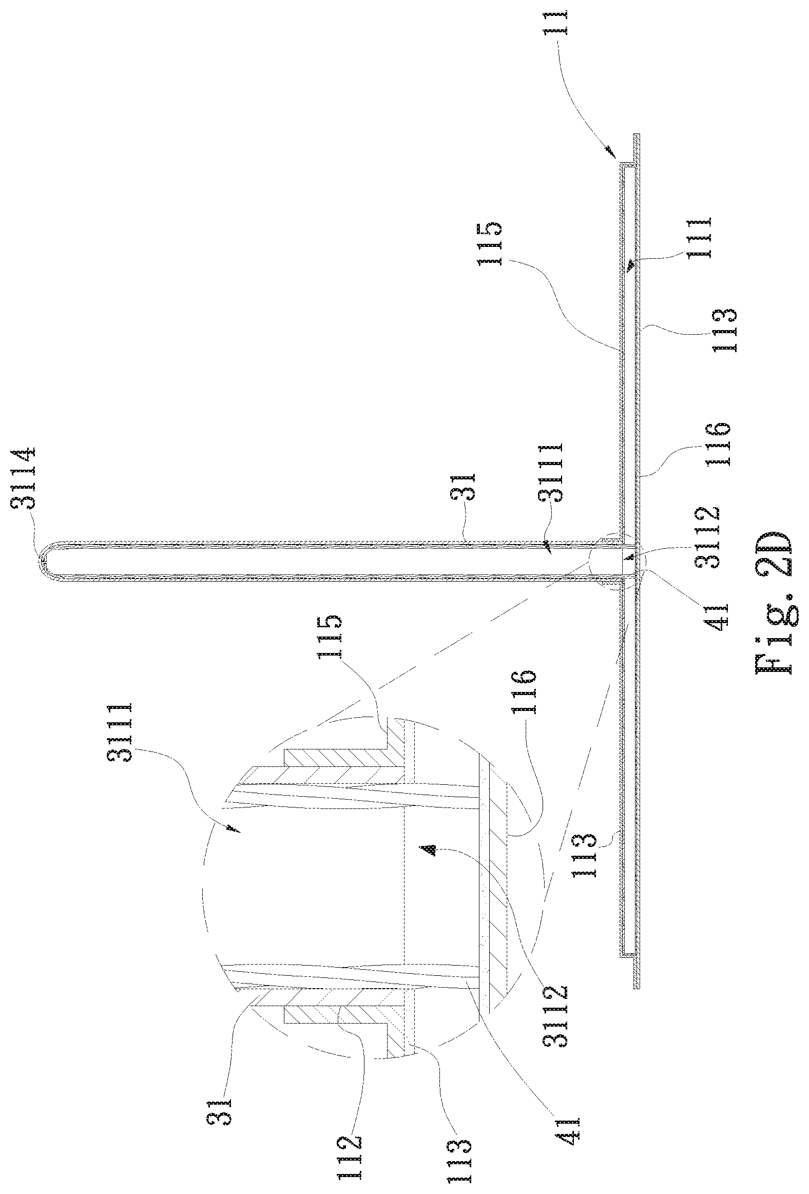
[0015] FIG. 2D is a sectional assembled view of a modified embodiment of the first embodiment of the present invention.
DETAILED DESCRIPTION OF THE PREFERRED EMBODIMENTS
[0016] Please refer to FIGS. 1 to 2D. FIG. 1 is a perspective exploded view of a first embodiment of the present invention. FIG. 2 is a perspective assembled view of the first embodiment of the present invention. FIG. 2A is a sectional assembled view of the first embodiment of the present invention. FIG. 2B is a sectional assembled view of a modified embodiment of the first embodiment of the present invention. FIG. 2C is a sectional assembled view of a modified embodiment of the first embodiment of the present invention. FIG. 2D is a sectional assembled view of a modified embodiment of the first embodiment of the present invention. According to the first embodiment, the heat dissipation unit with axial capillary structure of the present invention includes a case 11 and at least one tubular body 31. In this embodiment, the case 11 is, but not limited to, a vapor chamber. The case 11 has a case chamber 111, a top side 115, a bottom side 116 and at least one opening 112. The case chamber 111 is defined between the top side 115 and the bottom side 116. A working fluid (such as pure water or methanol, not shown) is filled in the case chamber 111. A case capillary structure 113 is formed in the case chamber 111. In a modified embodiment, the case 11 can be alternatively a heat plate or a flat-plate heat pipe.
[0017] In this embodiment, the case capillary structure 113 is, but not limited to, a sintered powder body formed on the inner wall of the case chamber 111, (that is, on the top side 115 and the bottom side 116 in the case chamber 111). In practice, the case capillary structure 113 disposed in the case chamber 111 can be alternatively a mesh body, a fiber, a channeled body, a whisker or any combination thereof. The opening 112 is formed through the top side 115 of the case 11 in communication with the case chamber 111. In this embodiment, there is one opening 112. In practice, the number of the openings 112 can be more than one. The number of the openings 112 is equal to the number of the tubular bodies 31 (such as heat pipes). In this embodiment, the tubular body 31 is a heat pipe. The tubular body 31 has at least one axial capillary structure 41, an open end 3112 and a closed end 3114 opposite to the open end 3112. The open end 3112 and the closed end 3114 together define a tubular body chamber 3111 positioned between the open end 3112 and the closed end 3114 in communication with the open end 3112. The open end 3112 of the tubular body 31 is directly plugged into the opening 112 of the case 11. The outer circumference of the tubular body 31 is tightly connected with the inner wall of the opening 112 of the case 11. The tubular body chamber 3111 communicates with the case chamber 111 via the open end 3112. The case chamber 111 is, but not limited to, in communication with the tubular body chamber 3111.
[0018] A connection section 3116 integrally extends from the open end 3112. The connection section 3116 extends into the case chamber 111 to directly abut against the bottom side 116 of the case 11. In addition, a notch or an opening is formed between the open end 3112 and the connection section 3116. The connection section 3116 is a part of the tubular body 31. The inner circumference of the connection section 3116 is exactly the inner circumference of the tubular body 31. Therefore, the connection section 3116 of the tubular body 31 is connected with the bottom side 116 in the case chamber 111 and the outer circumference of the tubular body 31 is connected with the inner wall of the opening 112 to form a support structure for the case chamber 111. Accordingly, it is unnecessary to provide (or there is not) any support copper column in the case chamber 111 connected between the top side 115 and the bottom side 116. This can achieve cost-saving effect.
[0019] Moreover, in this embodiment, the axial capillary structure 41 is formed of multiple fiber threads (such as metal material or nonmetal material of glass, fiber carbon or polymer fiber threads), which are stranded to form dense (or solid) axial capillary structure for providing excellent axial capillary attraction. In practice, the axial capillary structure 41 can be selected from a group consisting of fiber bundle, braid, channeled body and any combination thereof. It should be noted that the axial capillary structure of the present invention can be any capillary structure capable of providing axial capillary transfer effect for the working fluid. The axial capillary structure 41 is disposed on the inner circumference of the tubular body 31 and distributed in the longitudinal (or axial) direction of the tubular body 31 to directly abut against and connect with the case capillary structure 113 disposed on the bottom side of the case in the case chamber 111. In this embodiment, there are multiple axial capillary structures 41 axially extending from the inner side of the tubular body 31 in adjacency to the closed end 3114 to the connection section 3116. The axial capillary structures 41 directly contact and connect with the case capillary structure 113 disposed on the bottom side 116 of the case in the case chamber 111. Also, the axial capillary structures 41 contact and connect with the case capillary structure 113 disposed on the top side of the case in the case chamber 111 in adjacency to the opening. Therefore, the axial capillary structures 41 are disposed on the inner circumference of the tubular body chamber 3111 of the tubular body 31 in the longitudinal or axial direction of the tubular body 31 to provide axial capillary attraction. Under the axial capillary attraction of the axial capillary structures 41, the cooled working fluid (the liquid working fluid) will quickly axially flow back to the bottom side 116 in the case chamber 111. Accordingly, the working fluid can more efficiently flow in axial direction to achieve better heat dissipation effect. In addition, the axial capillary structures 41 axially disposed in the tubular body 31 serve as an axial capillary transfer path for the liquid working fluid, whereby the capillary transfer force for the liquid working fluid is enhanced to achieve better capillary transfer effect. In a preferred embodiment, the number of the axial capillary structures 41 can be previously adjusted in accordance with the heat dissipation requirement, the size of the tubular body 31 and the capillary transfer efficiency. For example, one or more axial capillary structures 41 are disposed on the inner circumference of the tubular body chamber 3111 of the tubular body 31. In another embodiment, a whisker structure or an oxide coating (such as hydrophilic coating) is disposed on the axial capillary structures 41.
[0020] As shown in FIG. 2D, in a modified embodiment, the connection section 3116 of the tubular body 31 is saved so as to increase the space (or vapor space) of the case chamber 111 for the liquid working fluid to flow. In still another modified embodiment, the case capillary structure 113 disposed on the top side 115 of the case 11 in the case chamber 111 can be saved and the case capillary structure 113 is simply disposed on the bottom side 116 of the case 11 in the case chamber 111 in direct contact with the axial capillary structures 41.
[0021] The application of the present invention is exemplified as follows:
[0022] The outer surface of the bottom side 116 of the case 11 is attached to a heat generation component (such as a central processing unit or MCU or any other electronic component necessitating heat dissipation) of an electronic apparatus (such as a computer, a notebook, an intelligent mobile device or a communication device, not shown), the bottom side 116 of the case 11 will absorb the heat generated by the heat generation component. At this time, the working fluid of the case capillary structure 113 on the bottom side 116 in the case chamber 111 will be heated and evaporated and converted into evaporated working fluid (or vapor working fluid). The vapor working fluid will flow to the top side 115 in the case chamber 111. Also, part of the vapor working fluid will pass through the open end 3112 of the tubular body 31 to flow into the tubular body chamber 3111. Then the vapor working fluid on the top side 115 in the case chamber 111 and at the closed end 3114 in the tubular body chamber 3111 is condensed and converted into cooled working fluid (liquid working fluid). Then, under the axial capillary attraction of the axial capillary structures 41, the cooled working fluid at the closed end 3114 in the tubular body chamber 3111 quickly axially flows back to the case capillary structure 113 on the bottom side 116 in the case chamber 111. Therefore, the vapor-liquid circulation of the working fluid continuously takes place within the case chamber 111 and the tubular body chamber 3111 to achieve better heat dissipation effect and better capillary transfer efficiency and enhance the heat transfer efficiency.
[0023] As shown in FIG. 2B, in a modified embodiment, a tubular body capillary structure 313 is disposed in the tubular body 31. In this embodiment, the tubular body capillary structure 313 is, but not limited to, a sintered powder body. In practice, the tubular body capillary structure 313 can be alternatively a mesh body, a fiber body, a channeled body, a whisker or any combination thereof. The tubular body capillary structure 313 is formed on the inner circumference of the tubular body chamber 3111 of the tubular body 31. The axial capillary structures 41 are disposed on the surface of the tubular body capillary structure 313 on the inner circumference of the tubular body 31 in contact and connection with the tubular body capillary structure 313. In addition, the tubular body capillary structure 313 and the axial capillary structures 41 at the open end 3112 of the tubular body 31 on the inner circumference of the tubular body 31 are in contact and connection with the case capillary structure 113 on the top side 115 and bottom side 116 in the case chamber 111. The axial capillary structures 41 provide axial capillary attraction for part of the cooled working fluid absorbed by the tubular body capillary structure 313, whereby the part of cooled working fluid will only specifically quickly flow in axial direction back to the case capillary structure 113 on the bottom side 116 in the case chamber 111. Also, under the capillary attraction of the tubular body capillary structure 313, the other part of cooled working fluid will flow back to the case capillary structure 113 on the bottom side 116 in the case chamber 111 in axial direction and radial direction. During the process, under the radial capillary attraction of the tubular body capillary structure 313, the cooled working fluid absorbed by the tubular body capillary structure 313 is transferred to the adjacent axial capillary structures 41. Accordingly, the axial capillary structures 41 simply provide axial capillary transfer path for the working fluid and the tubular body capillary structure 313 provides both axial and radial capillary transfer path for the working fluid. Therefore, better capillary transfer effect is achieved and the vapor-liquid circulation efficiency is enhanced.
[0024] As shown in FIG. 2C, in still another modified embodiment, the tubular body capillary structure 313 is alternatively disposed on one side or two sides of each axial capillary structure 41. In this embodiment, the tubular body capillary structure 313 is formed on two sides of each axial capillary structure 41 (or between each two adjacent axial capillary structures 41) on the inner circumference of the tubular body 31. The tubular body capillary structure 313 is in contact and connection with one side of each adjacent axial capillary structure 41 on the inner circumference of the tubular body 31. In addition, the tubular body capillary structure 313 and the axial capillary structure 41 are adjacently alternately disposed on the inner circumference of the tubular body 31. The tubular body capillary structure 313 and the axial capillary structures 41 at the open end 3112 of the tubular body 31 on the inner circumference of the tubular body 31 are in contact and connection with the case capillary structure 113 on the top side 115 and bottom side 116 in the case chamber 111. Accordingly, the axial capillary structures 41 simply provide axial capillary transfer path for the working fluid and the tubular body capillary structures 313 provide both axial and radial capillary transfer path for the working fluid. Therefore, better capillary transfer effect is achieved and the vapor-liquid circulation efficiency is enhanced.
[0025] Therefore, the heat dissipation unit with axial capillary structure of the present invention is able to achieve better capillary transfer effect and enhance the heat dissipation efficiency.
[0026] The present invention has been described with the above embodiments thereof and it is understood that many changes and modifications in such as the form or layout pattern or practicing step of the above embodiments can be carried out without departing from the scope and the spirit of the invention that is intended to be limited only by the appended claims.
* * * * *
D00000
D00001
D00002
D00003
D00004
D00005
D00006
XML
uspto.report is an independent third-party trademark research tool that is not affiliated, endorsed, or sponsored by the United States Patent and Trademark Office (USPTO) or any other governmental organization. The information provided by uspto.report is based on publicly available data at the time of writing and is intended for informational purposes only.
While we strive to provide accurate and up-to-date information, we do not guarantee the accuracy, completeness, reliability, or suitability of the information displayed on this site. The use of this site is at your own risk. Any reliance you place on such information is therefore strictly at your own risk.
All official trademark data, including owner information, should be verified by visiting the official USPTO website at www.uspto.gov. This site is not intended to replace professional legal advice and should not be used as a substitute for consulting with a legal professional who is knowledgeable about trademark law.