Immersion Tube For The Refrigerant Distribution In A Chiller
Behnert; Dominik ; et al.
U.S. patent application number 16/885255 was filed with the patent office on 2020-12-03 for immersion tube for the refrigerant distribution in a chiller. The applicant listed for this patent is Mahle International GmbH. Invention is credited to Christian Beger, Dominik Behnert, Timo Feldkeller.
| Application Number | 20200378685 16/885255 |
| Document ID | / |
| Family ID | 1000004873498 |
| Filed Date | 2020-12-03 |
| United States Patent Application | 20200378685 |
| Kind Code | A1 |
| Behnert; Dominik ; et al. | December 3, 2020 |
IMMERSION TUBE FOR THE REFRIGERANT DISTRIBUTION IN A CHILLER
Abstract
An immersion tube for the refrigerant distribution in a chiller may include a tubular shell that at least partially defines an interior space. The tube may also include at least two radial walls arranged within the interior space and that subdivide the interior space into at least two chambers that are separated from one another in a circumferential direction. The at least two radial walls may be structured as a single piece with the tubular shell. The at least two radial walls and the tubular shell may be formed as a one-piece extruded profile and may be twisted such that the at least two radial walls form a helix.
| Inventors: | Behnert; Dominik; (Leonberg, DE) ; Beger; Christian; (Thallwitz, DE) ; Feldkeller; Timo; (Asperg, DE) | ||||||||||
| Applicant: |
|
||||||||||
|---|---|---|---|---|---|---|---|---|---|---|---|
| Family ID: | 1000004873498 | ||||||||||
| Appl. No.: | 16/885255 | ||||||||||
| Filed: | May 27, 2020 |
| Current U.S. Class: | 1/1 |
| Current CPC Class: | F28D 15/00 20130101; F28D 20/0034 20130101; F28D 2020/0078 20130101 |
| International Class: | F28D 15/00 20060101 F28D015/00; F28D 20/00 20060101 F28D020/00 |
Foreign Application Data
| Date | Code | Application Number |
|---|---|---|
| May 28, 2019 | DE | 10 2019 207 799.4 |
Claims
1. An immersion tube for the refrigerant distribution in a chiller, comprising: a tubular shell that at least partially defines an interior space; at least two radial walls arranged within the interior space and that subdivide the interior space into at least two chambers that are separated from one another in a circumferential direction; wherein the at least two radial walls are structured as a single piece with the tubular shell; and wherein the at least two radial walls and the tubular shell are formed as a one-piece extruded profile and are twisted such that the at least two radial walls form a helix.
2. The immersion tube according to claim 13, wherein the helix is coupled within the tubular shell via at least one of a glued connection, a clamped connection, a welded connection, and a soldered connection.
3. The immersion tube according to claim 1, wherein, for each chamber of the at least two chambers, the tubular shell includes a shell-side opening of a plurality of shell-side openings.
4. The immersion tube according to claim 3, wherein the plurality of shell-side openings are disposed in a straight line.
5. The immersion tube according to claim 1, wherein: the at least two radial walls includes five radial walls; the at least two chambers includes five chambers; and the five radial walls separate the five chambers from one another.
6. The immersion tube according to claim 1, wherein the immersion tube is composed of aluminium.
7. A chiller, comprising: a stacked plate bundle; the immersion tube according to claim 1; an inlet; and wherein the immersion tube is arranged within the inlet.
8. A method for producing an immersion tube, comprising: producing a tubular shell that at least partially defines an interior space and a plurality of radial walls arranged within the interior space subdividing the interior space into a plurality of chambers that are separated from one another in a circumferential direction; after producing the plurality of radial walls, twisting the plurality of radial walls such that the plurality of radial walls form a helix; and wherein one of: producing the tubular shell and the plurality of radial walls includes forming the tubular shell and the plurality of radial walls as a one-piece extruded profile, and twisting the plurality of radial walls includes twisting the one-piece extruded profile; and producing the tubular shell and the plurality of radial walls includes forming the tubular shell and the plurality of radial walls as separate extruded profiles, and the method further comprises, after twisting the plurality of radial walls, coupling the helix within the tubular shell.
9. The method according to claim 8, further comprising introducing a plurality of shell-side openings into the tubular shell, and wherein a shell-side opening is introduced for each chamber of the plurality of chambers.
10. The method according to claim 8, wherein producing the tubular shell and the plurality of radial walls includes producing the tubular shell and the plurality of radial walls from aluminium.
11. The method according to claim 8, wherein the plurality of radial walls are produced and twisted such that the plurality of radial walls each have straight longitudinal ends.
12. The method according to claim 9, wherein introducing the plurality of shell-side openings into the tubular shell includes drilling the openings into the tubular shell.
13. An immersion tube for the refrigerant distribution in a chiller, comprising: a tubular shell that at least partially defines an interior space; at least two radial walls arranged within the interior space and that subdivide the interior space into at least two chambers that are separated from one another in a circumferential direction; wherein the at least two radial walls are structured separately from the tubular shell; wherein the at least two radial walls and the tubular shell are formed as separate extruded profiles and the at least two radial walls are twisted such that the at least two radial walls form a helix; and wherein the helix is coupled within the tubular shell.
14. The immersion tube according to claim 13, wherein the plurality of radial walls each have straight longitudinal ends.
15. The immersion tube according to claim 13, wherein, for each chamber of the at least two chambers, the tubular shell includes a shell-side opening of a plurality of shell-side openings.
16. The immersion tube according to claim 15, wherein the plurality of shell-side openings are disposed in a straight line.
17. The immersion tube according to claim 13, wherein: the at least two radial walls includes five radial walls; the at least two chambers includes five chambers; and the five radial walls separate the five chambers from one another.
18. The immersion tube according to claim 13, wherein the immersion tube is composed of aluminium.
19. The immersion tube according to claim 13, wherein: the at least two radial walls includes a plurality of radial walls; and the plurality of radial walls collectively define a cross section having a star-like shape.
20. A chiller, comprising: the immersion tube according to claim 13; a stacked plate bundle; an inlet; and wherein the immersion tube is arranged within the inlet.
Description
CROSS-REFERENCE TO RELATED APPLICATIONS
[0001] This application claims priority to German Patent Application No. DE 10 2019 207 799.4, filed on May 28, 2019, the contents of which is hereby incorporated by reference in its entirety.
TECHNICAL FIELD
[0002] The present invention relates to an immersion tube for the refrigerant distribution in a chiller having a tubular shell and at least two radial walls located inside. The invention, furthermore, relates to a chiller having a stacked plate bundle and such an immersion tube and to a method for producing such an immersion tube.
BACKGROUND
[0003] From DE 197 19 250 A1 a generic immersion tube having a tubular shell and altogether five radial walls located inside is known, which subdivide an interior space of the immersion tube into five chambers that are separated from one another in the circumferential direction. Each of the chambers has a shell-side opening via which refrigerant can exit. In this case, the immersion tube is formed as an integral die cast part and because of this is comparatively difficult technically and thus expensive to produce.
[0004] From DE 10 2012 105 481 A1 a condenser for a motor vehicle having a first and a second collection line is known, which are arranged separately from one another. Here, a heat exchanger section is arranged between the first and the second collection line and, via the first collection line, connected to a coolant tank. The coolant tank supplies the coolant to the heat exchanger section and receives the coolant that has flowed through the heat exchanger section and the second collection line via the first collection line. A collector-drier section is connected to the second collection line in order to carry out a gas/liquid separation and a dehumidification of the coolant, which has flowed through the heat exchanger section. An inner space of the coolant tank is separated into an upper and a lower section by means of a first separating means, which is arranged between the coolant inlet and the coolant outlet, wherein on the upper section a helical groove is formed, which causes the coolant to rotate.
[0005] From US 2006/0102331 A1 a further heat exchanger is known.
[0006] Generally, stacked plate heat exchangers which discharge heat from the coolant into evaporating refrigerant are increasingly employed in the field of the so-called thermal management of electric vehicles and fuel cell vehicles. In particular quick charging, during which large amounts of heat are generated within a short time, constitutes a major challenge for such a chiller since a high cooling output is required. For such a case, large chillers are employed, which comprises a multiplicity of stacked plates, over which a two-phase-mixed refrigerant is distributed. In terms of height, the portion of the gas phase should ideally be present on each stacked plate identically to the height of the liquid phase. In the operating state, in which the electric vehicle or the fuel cell vehicle travels in the so-called coasting mode, only a very small waste heat is still present so that the chiller runs only with very low load and a mass flow of the refrigerant drops and because of this another distribution of the two-phase-mixture is created than is the case for example during quick charging or under full load. For this reason it is not possible to date to supply the same gas/liquid portions of the refrigerant to the multiplicity of stacked plates for every operating case.
[0007] Such a problem can be solved for example by way of an immersion tube (without radial walls) in so-called S-flow chillers, in which the refrigerant is not only conveyed through the chiller in plate direction and re-exits on the other stacked plate side, but is additionally diverted in the height on the outlet side, again returned into the stacked disc plate, diverted once more and for the last time conducted via the stacked plate to the outlet. Here, the immersion tube serves for maintaining an inlet and outlet side on a component top side, which offers an installation space advantage. In addition, a refrigerant distribution in the plane can be optimised through suitable shell-side openings. However, disadvantageous here is the high pressure drop of the refrigerant which has a direct effect on the cooling output.
SUMMARY
[0008] The present invention therefore deals with the problem of stating an improved or at least an alternative embodiment for an immersion tube of the generic type which is characterized by a more cost-effective production.
[0009] According to the invention, this problem is solved through the subject matter of the independent claim(s). Advantageous embodiments are subject of the dependent claim(s).
[0010] The present invention is based on its general idea of producing an immersion tube as a cost-effective and twisted extruded component. The immersion tube according to the invention serves for the refrigerant distribution in a chiller, in particular in an electric vehicle or in a fuel cell vehicle and comprises a tubular shell and at least two radial walls located inside, which subdivide an interior space of the immersion tubes or of the tubular shell into at least two chambers that are separated from one another in the circumferential direction. Here, the radial walls are formed in one piece with the shell or separately from the same, for example in star-like shape. According to the invention, the radial walls and the tubular shell are now formed as a one-piece extruded profile and twisted in such a manner that the radial walls form a helix running in the axial direction of the immersion tube. Alternatively to this it is also conceivable that the radial walls and the tubular shell are formed as separate extruded profiles or the shell as reshaped punched part and the radial walls are twisted in such a manner that they form a helix, wherein the helix in this case is subsequently fixed in the tubular shell. By forming the immersion tube as a one-piece or multi-part extruded profile and twisting the radial walls, an immersion tubes can be created by means of which via suitable shell-side openings a uniform flow of refrigerant through the chiller can be achieved, as a result of which the problems in chillers in the stacked plate form known from the prior art can be minimised. By means of extruding, the immersion tube according to the invention cannot only be produced in very high quality but additionally also cost-effectively, wherein in a case the immersion tube is pressed through a suitable die stamp comprising both the radial walls and also the tubular shell. During the extrusion, solid to viscous, hardenable masses are continuously pressed under pressure out of a shaping opening, for example a die. The extruded profile created here has the cross section of the opening and can be produced in almost any length. By way of subsequent twisting either of the radial walls alone or of the entire immersion tube, the radial walls can be reshaped into the helix, wherein through a subsequent provision of a shell-side opening on each chamber a preferentially uniform charging of the chiller with refrigerant is possible. Altogether, such an immersion tube can be produced significantly more cost-effectively than a comparable immersion tube produced as a die-cast component.
[0011] In an advantageous further development of the solution according to the invention according to the second alternative, the helix in the tubular shell is fixed through a glued connection, a clamped connection or a soldered connection. Even this non-conclusive enumeration shows the manifold connecting possibilities of the helix that are possible in the tubular shell, wherein in particular a soldering appears advantageous.
[0012] Practically, a shell-side opening for each chamber is provided in the tubular shell. By way of a shell-side opening belonging to a respective chamber a uniform expulsion of refrigerant over the entire length of the immersion tube can be achieved, as a result of which in turn a uniform charging of the chiller with refrigerant is made possible. In particular, supplying the chiller with same gas-liquid portions of the refrigerant in any operating state can also take place by way of this.
[0013] Practically, the shell-side openings lie on a straight line. When for example five radial walls are provided, which separate five chambers from one another in the circumferential direction, at least five shell-side openings are also introduced, for example through a punching or drilling later on, which preferentially lie on a straight line. By way of this, a chiller can be supplied with refrigerant with the immersion tube according to the invention over the entire height almost uniformly and irrespective of the operating state.
[0014] From a further advantageous embodiment of the solution according to the invention, the immersion tube is produced from aluminium. Aluminium constitutes a particularly preferred material with regard to extruding and additionally offers a high heat conduction coefficient, as a result of which the use of aluminium is of great advantage in particular in the region of a chiller.
[0015] The present invention, furthermore, is based on the general idea of equipping a chiller in stacked plate design with an immersion tube introduced therein on the inlet side. By way of this, a chiller can be created which by way of the immersion tube according to the invention, seen over the height and irrespective of the operating state, i.e. in particular irrespective of load, is uniformly supplied with refrigerant. By way of this, an almost identical gas-liquid portion of the refrigerant can also be achieved in each plate.
[0016] The present invention is based, furthermore, on the general idea of stating a method for producing a previously described immersion tube, in which initially a tubular shell with radial walls arranged therein is produced as a one-piece extruded profile and subsequently twisted in such a manner that the radial walls from a helix running in the longitudinal direction of the immersion tube. Alternatively to this it is conceivable that the radial walls and the tubular shell are produced as separate extruded profiles or the shell as reshaped punched part and subsequently only the radial walls are twisted in such a manner that they form a helix, wherein the helix thus produced is subsequently fixed, for example glued, welded, clamped or soldered in the tubular shell, which can also be produced as a punched part. Both alternatives of the production method according to the invention have in common that the immersion tube altogether can be produced cost-effectively and not, as in the past, as expensive die cast component that is difficult to produce technically. Obviously, shell-side openings still have to be introduced following this in order to be able to create outlet openings for the refrigerant later on. Here, at least one shell opening is introduced for each chamber, in particular drilled in or punched. With the method according to the invention, the immersion tube can thus be produced cost-effectively yet in high quality, in particular compared with immersion tubes produced or formed as die-cast components known from the prior art to date.
[0017] Further important features and advantages of the invention are obtained from the subclaims, from the drawing and from the associated FIGURE description by way of the drawing.
[0018] It is to be understood that the features mentioned above and still to be explained in the following cannot only be used in the respective combination stated but also in other combinations or by themselves without leaving the scope of the present invention.
[0019] A preferred exemplary embodiment of the invention is shown in the drawing and is explained in more detail in the following description.
BRIEF DESCRIPTION OF THE DRAWINGS
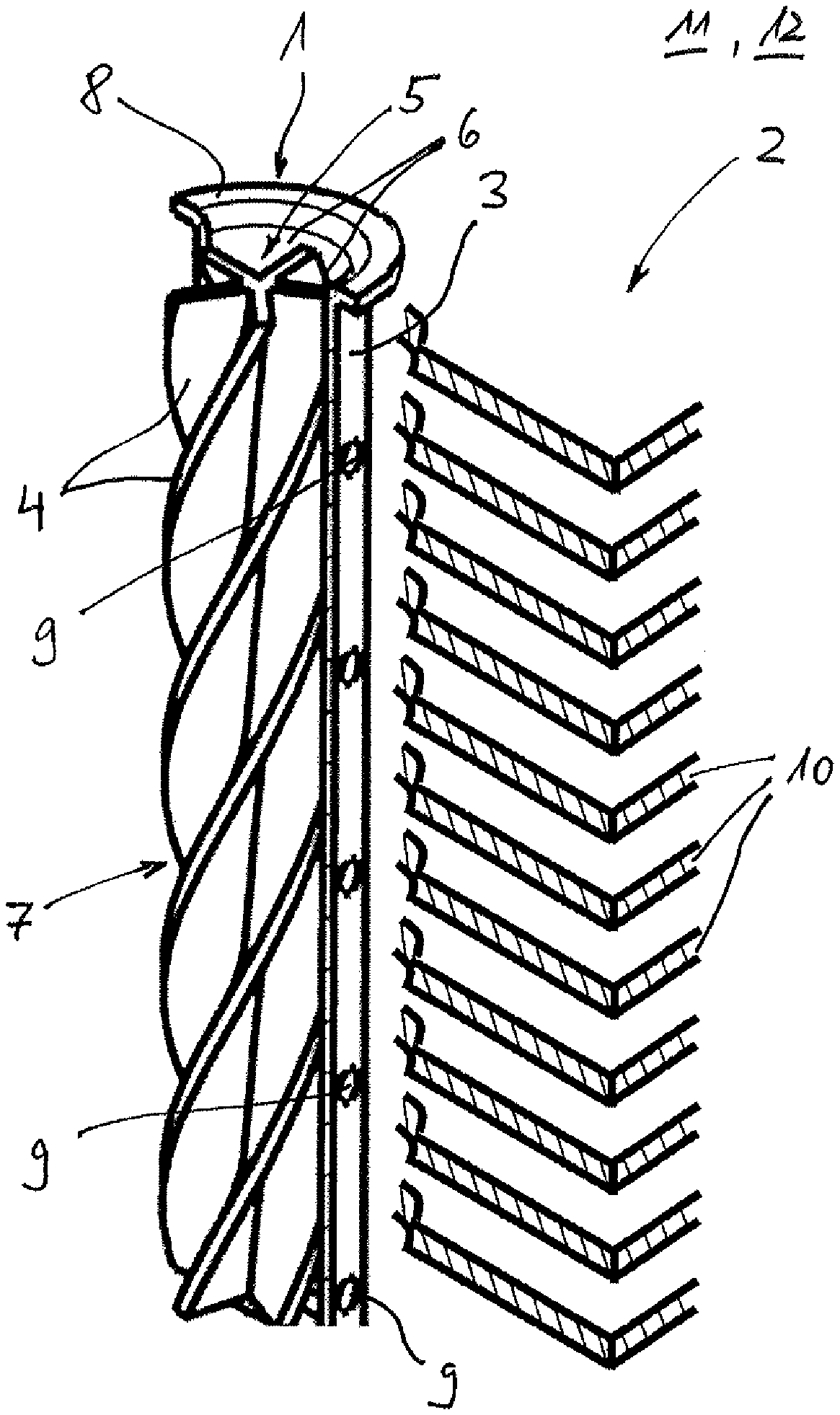
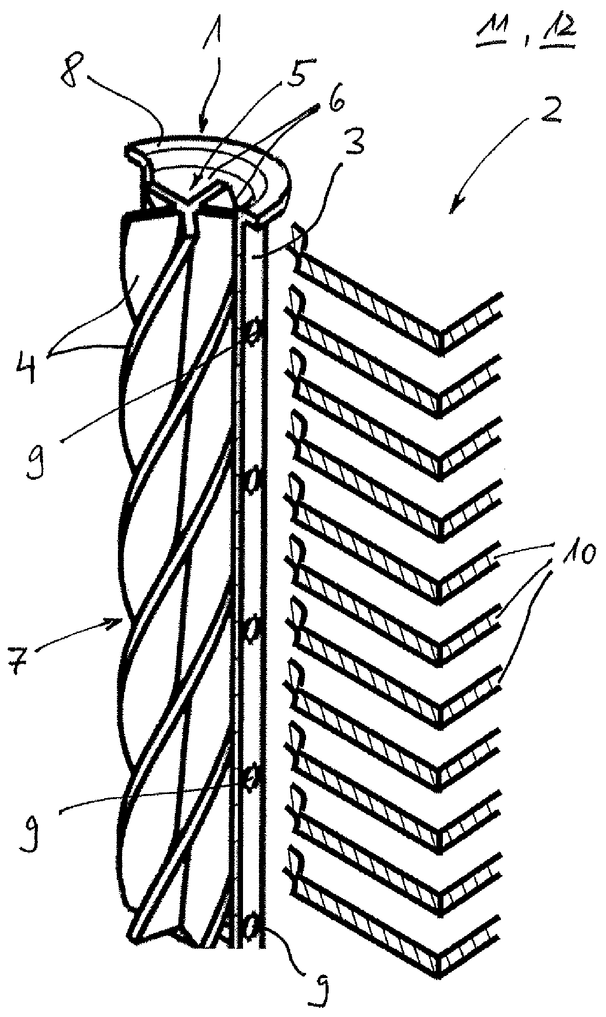
[0020] The only FIGURE shows a partly sectioned view through an immersion tube according to the invention and a chiller according to the invention.
DETAILED DESCRIPTION
[0021] According to the FIGURE, an immersion tube 1 according to the invention, which is employed for the refrigerant distribution in a chiller 2, comprises a tubular shell 3 and at least two radial walls 4 located inside, here five radial walls 4 located inside, which subdivide an interior space of the immersion tube 1 into at least two, here altogether five, chambers 6 separated from one another in the circumferential direction. Here, the radial walls 4 are formed in one piece with the shell 3 or separately from the same. According to the FIGURE, only half of the shell 3 is drawn in order to obtain a better view of the radial walls 4 represented as helix 7. Here, the chiller 2 comprises a stacked plate bundle and an immersion tube 1 introduced into an inlet.
[0022] According to the invention, the radial walls 4 and the tubular shell 3 are formed as a one-piece extruded profile and twisted in such a manner that the radial walls 4 form the previously mentioned helix 7. Alternatively it is also conceivable that the radial walls 4 and the tubular shell 3 are formed as separated extruded profiles or the shell 3 as reshaped punched part and the radial walls 4 twisted in such a manner that they form a helix 7. In this case, the finish-twisted helix 7 would have to be fixed in the tubular shell 3 later on. The tubular shell 3 according to the FIGURE comprises a collar 8 which can be produced for example by way of a separate forming process or which, during a later processing step, connected to the immersion tube 1.
[0023] When the immersion tube according to the invention is produced according to the second alternative, i.e. with radial walls 4 separated from the tubular shell 3, the helix 7 formed from the radial walls 4 is subsequently fixed in the tubular shell 3, for example by way of a glued connection, a clamped connection or a soldered connection. Purely theoretically, welding is obviously also conceivable. In the embodiment of the immersion tube 1 according to the invention shown according to the FIGURE, the same comprises altogether five radial walls 4 which star-like originate from a centre point. Obviously, more or fewer, however at least two radial walls 4 can be provided, which form chambers 6 that are separated from one another in the circumferential direction. The number of the radial walls 4 corresponds to the number of the chambers 6 separated by these.
[0024] Viewing the immersion tube 1 according to the FIGURE further it is noticeable that for each chamber 6 a shell-side opening 9 is provided in the tubular shell 3, via which refrigerant can flow out. By way of this it is possible in particular with a chiller 2, to evenly supply layers between different stacked plates 10 evenly and in particular regardless of operating state and load with refrigerant. By way of this, a uniform gas/liquid mixture can also be produced in particular.
[0025] According to the FIGURE it is noticeable, furthermore, that the shell-side openings 9 lie on a straight line, wherein another arrangement is obviously also conceivable, and wherein via the arrangement of the shell-side openings 9, influencing in particular an inflow behaviour of refrigerant via the immersion tube 1 into the chiller 2 is possible.
[0026] Practically, the immersion tube 1 according to the invention is produced from aluminium which creates not only a durable structure. The chiller 2 according to the invention, which is equipped with the immersion tube 1 according to the invention, can be employed for example in an electric vehicle 11 or a fuel cell vehicle 12.
[0027] The immersion tube 1 according to the invention is produced by means of a production method according to the invention, which is described in more detail in the following:
[0028] Initially, a tubular shell 3 with radial walls 4 arranged therein is produced as a one-piece extruded profile, i.e. extruded, and subsequently twisted, upon which the radial walls 4 assume the helical shape shown in FIG. 1. Alternatively it is obviously also conceivable that the radial walls 4 and the tubular shell 3 are initially produced as separate extruded profiles or the shell produced as reshaped punched part with introduced openings 9, which subsequently the radial walls 4, which in the present case have a star-shaped cross section, are twisted in such a manner that they form the described helix 7. Again subsequently, this twisted helix 7 is fixed in the tubular shell 3 or clamped, welded, glued or soldered in the same. Further, the shell-side openings 9 have to be provided, which can be produced for example in a subsequent process step, for example by drilling or punching. With the method according to the invention the immersion tube 1 according to the invention can be produced in a significantly simpler and thus more cost-effective manner.
* * * * *
D00000
D00001
XML
uspto.report is an independent third-party trademark research tool that is not affiliated, endorsed, or sponsored by the United States Patent and Trademark Office (USPTO) or any other governmental organization. The information provided by uspto.report is based on publicly available data at the time of writing and is intended for informational purposes only.
While we strive to provide accurate and up-to-date information, we do not guarantee the accuracy, completeness, reliability, or suitability of the information displayed on this site. The use of this site is at your own risk. Any reliance you place on such information is therefore strictly at your own risk.
All official trademark data, including owner information, should be verified by visiting the official USPTO website at www.uspto.gov. This site is not intended to replace professional legal advice and should not be used as a substitute for consulting with a legal professional who is knowledgeable about trademark law.