Electric Supercharger
SHIBATA; Naomichi ; et al.
U.S. patent application number 16/326640 was filed with the patent office on 2020-12-03 for electric supercharger. This patent application is currently assigned to MITSUBISHI HEAVY INDUSTRIES, LTD.. The applicant listed for this patent is MITSUBISHI HEAVY INDUSTRIES ENGINE & TURBOCHARGER, LTD., MITSUBISHI HEAVY INDUSTRIES, LTD.. Invention is credited to Byeongil AN, Yutaka FUJITA, Tadashi KANZAKA, Naomichi SHIBATA, Akihiro SUGIYAMA.
| Application Number | 20200378389 16/326640 |
| Document ID | / |
| Family ID | 1000005051083 |
| Filed Date | 2020-12-03 |


View All Diagrams
| United States Patent Application | 20200378389 |
| Kind Code | A1 |
| SHIBATA; Naomichi ; et al. | December 3, 2020 |
ELECTRIC SUPERCHARGER
Abstract
An electric supercharger includes: a compressor impeller; a motor configured to transmit a driving force to the compressor impeller via a rotational shaft; a back-surface side casing facing a back surface of the compressor impeller via a gap and surrounding the rotational shaft; a bearing disposed between the back-surface side casing and the rotational shaft so as to support the rotational shaft rotatably; and a mechanical seal positioned between the back surface of the compressor impeller and the bearing in an axial direction of the compressor impeller and configured to seal a gap between the rotational shaft and the back-surface side casing.
| Inventors: | SHIBATA; Naomichi; (Sagamihara-shi, JP) ; AN; Byeongil; (Sagamihara-shi, JP) ; SUGIYAMA; Akihiro; (Sagamihara-shi, JP) ; FUJITA; Yutaka; (Tokyo, JP) ; KANZAKA; Tadashi; (Tokyo, JP) | ||||||||||
| Applicant: |
|
||||||||||
|---|---|---|---|---|---|---|---|---|---|---|---|
| Assignee: | MITSUBISHI HEAVY INDUSTRIES,
LTD. Tokyo JP MITSUBISHI HEAVY INDUSTRIES ENGINE & TURBOCHARGER, LTD. Sagamihara-shi, Kanagawa JP |
||||||||||
| Family ID: | 1000005051083 | ||||||||||
| Appl. No.: | 16/326640 | ||||||||||
| Filed: | March 29, 2017 | ||||||||||
| PCT Filed: | March 29, 2017 | ||||||||||
| PCT NO: | PCT/JP2017/012938 | ||||||||||
| 371 Date: | February 19, 2019 |
| Current U.S. Class: | 1/1 |
| Current CPC Class: | F04D 29/284 20130101; F04D 29/102 20130101; F04D 25/06 20130101; F04D 29/056 20130101 |
| International Class: | F04D 25/06 20060101 F04D025/06; F04D 29/10 20060101 F04D029/10; F04D 29/28 20060101 F04D029/28; F04D 29/056 20060101 F04D029/056 |
Claims
1. An electric supercharger, comprising: a compressor impeller; a motor configured to transmit a driving force to the compressor impeller via a rotational shaft; a back-surface side casing facing a back surface of the compressor impeller via a gap and surrounding the rotational shaft; a bearing disposed between the back-surface side casing and the rotational shaft so as to support the rotational shaft rotatably; and a mechanical seal positioned between the back surface of the compressor impeller and the bearing in an axial direction of the compressor impeller and configured to seal a gap between the rotational shaft and the back-surface side casing, wherein the mechanical seal includes: a stationary ring supported on the back-surface side casing; a rotary ring protruding from the rotational shaft toward an outer side in a radial direction of the compressor impeller and facing the stationary ring so as to be capable of being in contact with the stationary ring in the axial direction of the compressor impeller, the rotary ring being configured to rotate with the rotational shaft; and a biasing member configured to bias one of the rotary ring or the stationary ring toward the other one of the rotary ring or the stationary ring, and wherein a groove is formed on a facing surface which is one of a surface of the rotary ring which faces the stationary ring or a surface of the stationary ring which faces the rotary ring.
2. (canceled)
3. The electric supercharger according to claim 1, wherein the back surface of the compressor impeller has a plurality of ribs disposed on the back surface at intervals in a circumferential direction of the compressor impeller.
4. The electric supercharger according to claim 3, wherein each of the ribs is disposed to so as to extend along a direction which intersects with the circumferential direction of the compressor impeller.
5. The electric supercharger according to claim 3, wherein each of the ribs has an airfoil shape.
6. The electric supercharger according to claim 3, wherein each of the ribs is disposed so as to extend in a direction inclined from a radial direction of the compressor impeller such that a radially outer end of the rib is positioned on an upstream side of a radially inner end of the rib with respect to a rotational direction of the compressor impeller.
7. An electric supercharger, comprising: a compressor impeller; a motor configured to transmit a driving force to the compressor impeller via a rotational shaft; a back-surface side casing facing a back surface of the compressor impeller via a gap and surrounding the rotational shaft; a bearing disposed between the back-surface side casing and the rotational shaft so as to support the rotational shaft rotatably; a mechanical seal positioned between the back surface of the compressor impeller and the bearing in an axial direction of the compressor impeller and configured to seal a gap between the rotational shaft and the back-surface side casing; and between the mechanical seal and the back surface of the compressor impeller, a rotary part protruding from the rotational shaft toward an outer side in a radial direction of the compressor impeller, the rotary part being configured to rotate together with the rotational shaft.
8. The electric supercharger according to claim 1, further comprising an abradable coating layer formed on at least a part of the back surface of the compressor impeller, or at least a part of a surface of the back-surface side casing which faces the back surface of the compressor impeller.
9. The electric supercharger according to claim 8, wherein a ratio G/R of a size G of a gap between the back surface of the compressor impeller and the back-surface side casing to an outer diameter R of the compressor impeller is less than 0.5%.
10. The electric supercharger according to claim 1, further comprising an internal-pressure adjustment mechanism configured to adjust a pressure inside the back-surface side casing by bringing into communication an inside and an outside of the back-surface side casing.
11. The electric supercharger according to claim 7, further comprising an abradable coating layer formed on at least a part of the back surface of the compressor impeller, or at least a part of a surface of the back-surface side casing which faces the back surface of the compressor impeller.
12. The electric supercharger according to claim 11, wherein a ratio G/R of a size G of a gap between the back surface of the compressor impeller and the back-surface side casing to an outer diameter R of the compressor impeller is less than 0.5%.
13. The electric supercharger according to claim 7, further comprising an internal-pressure adjustment mechanism configured to adjust a pressure inside the back-surface side casing by bringing into communication an inside and an outside of the back-surface side casing.
Description
TECHNICAL FIELD
[0001] The present disclosure relates to an electric supercharger.
BACKGROUND ART
[0002] In an engine device of an automobile or the like, to improve the engine fuel consumption and the efficiency, an exhaust turbine is driven by exhaust gas discharged from the engine to coaxially drive a compressor disposed in an intake passage and compress intake gas supplied to engine, which is called "supercharging".
[0003] In this supercharging using a turbocharger, the torque and the output during low-speed rotation of the engine may raise problems, due to response delay during low-speed rotation of the engine, called turbo lag. A known technique to make up for the response delay due to turbo lag is a two-stage supercharging system which includes a turbocharger driven by exhaust gas and an electric supercharger driven by an electric motor (see Patent Document 1).
CITATION LIST
Patent Literature
[0004] Patent Document 1: JP2015-537162A (translation of a PCT application)
SUMMARY
Problems to be Solved
[0005] Meanwhile, in an electric supercharger, the compressor is driven by a motor, unlike a turbocharger. Thus, devices such as a motor and an inverter substrate are disposed behind the compressor (between the compressor impeller and the bearing).
[0006] Thus, when a leakage flow passes through the gap between the back surface of the compressor impeller and the casing and enters the bearing side, the leakage flow may affect devices such as the motor and the inverter substrate.
[0007] In particular, in a case where a part of exhaust gas is recirculated in a two-stage supercharging system including an EGR and a case where an intermediate cooler is used, and a case where blow-by gas is returned to the inlet of the compressor, for instance, air containing condensed water is taken in from the inlet of the compressor, and thus a leakage flow passing through the gap between the back surface of the compressor impeller and entering the bearing side may cause trouble in operation of devices such as the motor and the inverter.
[0008] Further, in particular, in a case where an electric supercharger is applied to the high-pressure stage of a two-stage supercharging system, high-temperature and high-pressure air flows in from the inlet of the compressor. Thus, a leakage flow passing through the gap between the back surface of the compressor impeller and entering the bearing side may cause trouble in operation of devices such as the motor and the inverter.
[0009] At least one embodiment of the present invention was made in view of the above conventional problem. An object of at least one embodiment of the present invention is to provide an electric supercharger capable of suppressing entry of a leakage flow to the bearing side via the gap between the back surface of the compressor impeller and the casing.
Solution to the Problems
[0010] (1) According to at least one embodiment of the present invention, an electric supercharger includes: a compressor impeller; a motor configured to transmit a driving force to the compressor impeller via a rotational shaft; a back-surface side casing facing a back surface of the compressor impeller via a gap and surrounding the rotational shaft; a bearing disposed between the back-surface side casing and the rotational shaft so as to support the rotational shaft rotatably; and a mechanical seal positioned between the back surface of the compressor impeller and the bearing in an axial direction of the compressor impeller and configured to seal a gap between the rotational shaft and the back-surface side casing.
[0011] With the above electric supercharger (1), it is possible to suppress entry of a leakage flow from the gap between the back surface and the back-surface side casing (hereinafter, referred to as "back-surface gap") to the bearing by using the mechanical seal, and suppress inflow of the leakage flow into electric devices such as the motor. Thus, it is possible to suppress occurrence of malfunction or the like of the electric devices, and operate the electric supercharger stably.
[0012] (2) In some embodiment, in the above electric supercharger (1), the mechanical seal includes: a stationary ring supported on the back-surface side casing; a rotary ring protruding from the rotational shaft toward an outer side in a radial direction of the compressor impeller and facing the stationary ring so as to be capable of being in contact with the stationary ring in the axial direction of the compressor impeller, the rotary ring being configured to rotate with the rotational shaft; and a biasing member configured to bias one of the rotary ring or the stationary ring toward the other one of the rotary ring or the stationary ring. A groove is formed on a facing surface which is one of a surface of the rotary ring which faces the stationary ring or a surface of the stationary ring which faces the rotary ring.
[0013] With the above electric supercharger (2), when rotation of the compressor impeller is stopped, as the biasing member pushes one of the rotary ring or the stationary ring against the other one of the rotary ring or the stationary ring, the mechanical seal functions as a contact seal. Accordingly, it is possible to suppress entry of a leakage flow from the back-surface gap to the bearing, and suppress inflow of the leakage flow into electric devices such as the motor. Thus, it is possible to suppress occurrence of malfunction or the like of the electric devices, and operate the electric supercharger stably.
[0014] Further, when the compressor impeller is rotating, the pressure of gas inside the groove having a pressure increased by a centrifugal force separates the stationary ring and the rotary ring against the biasing force of the biasing member. Accordingly, the stationary ring and the rotary ring separate from each other (not in contact). Nevertheless, with the pressure of the space on the inner side of the facing surface being higher than the pressure of the space on the outer side of the facing surface, it is possible to suppress entry of a leakage flow from the back-surface gap to the bearing. Accordingly, it is possible to suppress inflow of the leakage flow to electric devices such as the motor. Thus, it is possible to suppress occurrence of malfunction or the like of the electric devices, and operate the electric supercharger stably.
[0015] (3) In some embodiments, in the above electric supercharger (1) or (2), the back surface of the compressor impeller has a plurality of ribs disposed on the back surface at intervals in a circumferential direction of the compressor impeller.
[0016] With the above electric supercharger (3), by providing the plurality of ribs, a centrifugal force toward the outer side in the radial direction is applied to air in the back-surface gap upon rotation of the compressor impeller, and thereby it is possible to decrease the pressure of the radially inner part of the back-surface gap. Accordingly, it is possible to suppress entry of a leakage flow from the back-surface gap to the bearing, and suppress inflow of the leakage flow into electric devices such as the motor. Further, when applied to the above electric supercharger (2), by reducing the pressure of the radially inner part of the back-surface gap, it is possible to decrease the spring force of the biasing member required to move the stationary ring appropriately, which makes it possible to suppress development of wear due to friction between the stationary ring and the rotary ring.
[0017] (4) In some embodiments, in the above electric supercharger (3), each of the ribs is disposed to so as to extend along a direction which intersects with the circumferential direction of the compressor impeller.
[0018] With the above electric supercharger (4), the plurality of ribs extending in a direction orthogonal to the circumferential direction rotates with the compressor impeller, and thus it is possible to apply the centrifugal force toward the outer side in the radial direction effectively to air in the back-surface gap, and reduce the pressure of the radially inner part of the back-surface gap. Accordingly, it is possible to suppress entry of a leakage flow from the back-surface gap to the bearing, and suppress inflow of the leakage flow into electric devices such as the motor.
[0019] (5) In some embodiments, in the above configuration (3) or (4), each of the ribs has an airfoil shape.
[0020] With the above electric supercharger (5), it is possible to form an airflow toward the outer side in the radial direction effectively with the ribs having an airfoil shape, in the back-surface gap upon rotation of the compressor impeller. Accordingly, it is possible to suppress entry of a leakage flow from the back-surface gap to the bearing, and suppress inflow of the leakage flow into electric devices such as the motor.
[0021] (6) In some embodiments, in the electric supercharger according to any one of the above (3) to (5), each of the ribs is disposed so as to extend in a direction inclined from a radial direction of the compressor impeller such that a radially outer end of the rib is positioned on an upstream side of a radially inner end of the rib with respect to a rotational direction of the compressor impeller.
[0022] With the above electric supercharger (6), with the ribs being inclined in the above direction, it is possible to suppress inflow of air into the gaps between the ribs from the outer side in the radial direction, during rotation of the compressor impeller. Accordingly, it is possible to suppress entry of a leakage flow from the back-surface gap to the bearing, and suppress inflow of the leakage flow into electric devices such as the motor.
[0023] (7) In some embodiments, the electric supercharger according to any one of the above (1) to (6) further includes, between the mechanical seal and the back surface of the compressor impeller, a rotary part protruding from the rotational shaft toward an outer side in a radial direction of the compressor impeller, the rotary part being configured to rotate together with the rotational shaft.
[0024] With the above electric supercharger (7), upon rotation of the compressor impeller, a centrifugal force toward the outer side in the radial direction is applied to air in the back-surface gap in accordance with rotation of the rotary part, and thereby it is possible to decrease the pressure of the radially inner part of the back-surface gap. Accordingly, it is possible to suppress entry of a leakage flow from the back-surface gap to the bearing, and suppress inflow of the leakage flow into electric devices such as the motor. Further, when applied to the above electric supercharger (2), by reducing the pressure of the radially inner part of the back-surface gap, it is possible to decrease the spring force of the biasing member required to move the stationary ring appropriately, which makes it possible to suppress development of wear due to friction between the stationary ring and the rotary ring.
[0025] (8) In some embodiments, the electric supercharger according to any one of the above (1) to (7) further includes an abradable coating layer formed on at least a part of the back surface of the compressor impeller, or at least a part of a surface of the back-surface side casing which faces the back surface of the compressor impeller.
[0026] With the above electric supercharger (8), in a case where the abradable coating layer is formed on at least a part of the back surface of the compressor impeller, the abradable coating layer would be ground upon rotation of the compressor impeller even if the abradable coating layer formed on the back surface of the compressor impeller makes contact with a surface of the back-surface side casing that faces the back surface of the compressor impeller. Thus, it is possible to reduce the clearance between the back surface and the back-surface side casing.
[0027] Furthermore, in a case where the abradable coating layer is formed on at least a part of a surface of the back-surface side casing that faces the back surface of the compressor impeller, the abradable coating layer would be ground upon rotation of the compressor impeller even if the abradable coating layer formed on a facing surface of the back-surface side casing that faces the back surface of the compressor impeller makes contact with the back surface of the compressor impeller. Thus, it is possible to reduce the clearance between the back surface and the back-surface side casing.
[0028] Accordingly, it is possible to promote a pressure decrease toward the inner side in the radial direction, in the back-surface gap. Thus, it is possible to reduce the axial-directional pressure difference between the pressure of the radially inner part and the pressure near the bearing, of the back-surface gap, and thus it is possible to suppress entry of a leakage flow toward the bearing from the back-surface gap. Accordingly, it is possible to suppress inflow of the leakage flow into electric devices such as the motor and an inverter. Thus, it is possible to suppress occurrence of malfunction or the like of the electric devices, and operate the electric supercharger stably.
[0029] Further, the compressor impeller receives a thrust force toward the upstream in the intake direction of air, in the axial direction, when air is compressed. In the above electric supercharger, it is possible to reduce the pressure in the back-surface gap for the compressor impeller, and thus it is possible to reduce the thrust force in the axial direction.
[0030] Further, by promoting the pressure decrease toward the inner side in the radial direction in the back-surface gap to reduce the pressure of the radially inner part of the back-surface gap, it is possible to decrease the spring force of the biasing member required to move the stationary ring of the mechanical seal appropriately, which makes it possible to suppress development of wear due to friction between the stationary ring and the rotary ring.
[0031] (9) In some embodiments, in the electric supercharger (8), a ratio G/R of a size G of a gap between the back surface of the compressor impeller and the back-surface side casing to an outer diameter R of the compressor impeller is less than 0.5%.
[0032] With the above electric supercharger (9), it is possible to promote a pressure decrease toward the inner side in the radial direction, in the back-surface gap, effectively. According to the inventors of the present invention, when comparing a case where the abradable coating layer is provided and the ratio C/Ri is set to be 0.8% and a case where the abradable coating layer is not provided and C/Ri is set to be 0.25%, the former can reduce more pressure of the radially inner part of the back-surface gap by 26% compared to the latter.
[0033] (10) In some embodiments, the electric supercharger according to any one of the above (1) to (9) further includes an internal-pressure adjustment mechanism configured to adjust a pressure inside the back-surface side casing by bringing into communication an inside and an outside of the back-surface side casing.
[0034] With the above electric supercharger (10), in the electric supercharger according to any one of the above (1) to (9), even in a case where the pressure of the radially inner part of the back-surface gap is low, it is possible to stabilize the pressure balance across the mechanical seal by adjusting the pressure inside and outside the back-surface side casing by using the pressure adjustment mechanism. Accordingly, it is possible to suppress entry of a leakage flow to the bearings through the back-surface gap stably with the mechanical seal.
Advantageous Effects
[0035] According to at least one embodiment of the present invention, it is possible to provide an electric supercharger capable of suppressing entry of a leakage flow to the bearing side via the gap between the back surface of the compressor impeller and the casing.
BRIEF DESCRIPTION OF DRAWINGS
[0036] FIG. 1 is a schematic diagram showing a schematic cross-sectional view of an electric supercharger 2 according to an embodiment.
[0037] FIG. 2 is a schematic diagram showing a schematic cross-sectional view in the vicinity of a back surface 16 of a compressor impeller 4 of an electric supercharger 2 (2A) according to an embodiment, showing a configuration example of a mechanical seal 20.
[0038] FIG. 3 is a view of a compressor impeller 4 in rotation, in the electric supercharger 2 (2A) depicted in FIG. 2.
[0039] FIG. 4 is a schematic diagram showing a schematic cross-sectional view in the vicinity of a back surface 16 of a compressor impeller 4 of an electric supercharger 2 (2B) according to an embodiment.
[0040] FIG. 5 is a diagram showing a configuration example of the ribs 44 depicted in FIG. 4, showing an example of arrangement of the ribs 44 in an axial-directional view.
[0041] FIG. 6 is a diagram showing a configuration example of the ribs 44 depicted in FIG. 4, showing an example of arrangement of the ribs 44 in an axial-directional view.
[0042] FIG. 7 is a schematic diagram showing a schematic cross-sectional view in the vicinity of a back surface 16 of a compressor impeller 4 of an electric supercharger 2 (2C) according to an embodiment.
[0043] FIG. 8 is a diagram showing a configuration example of the rotary part 50 depicted in FIG. 7, showing an example of the shape of the rotary part 50 in an axial-directional view.
[0044] FIG. 9 is a diagram showing a configuration example of the rotary part 50 depicted in FIG. 7, showing an example of the shape of the rotary part 50 in an axial-directional view.
[0045] FIG. 10 is a diagram showing a configuration example of the rotary part 50 depicted in FIG. 7, showing an example of the shape of the rotary part 50 in an axial-directional view.
[0046] FIG. 11 is a schematic diagram showing a schematic cross-sectional view in the vicinity of a back surface 16 of a compressor impeller 4 of an electric supercharger 2 (2D) according to an embodiment.
[0047] FIG. 12 is a graph showing the relationship between the radial-directional position R and the gauge pressure P of the back-surface gap `g`. The dotted line indicates an electric supercharger 2 (2A) not including an abradable coating layer 90, and the solid line indicates an electric supercharger 2 (2D) including an abradable coating layer 90 formed on the facing surface 21.
[0048] FIG. 13 is a schematic diagram showing a schematic cross-sectional view in the vicinity of a back surface 16 of a compressor impeller 4 of an electric supercharger 2 (2E) according to an embodiment.
[0049] FIG. 14 is a diagram showing an example of arrangement of a communication hole 53 that serves as an internal-pressure adjustment mechanism.
[0050] FIG. 15 is a diagram showing an example of arrangement of a communication hole 53 that serves as an internal-pressure adjustment mechanism.
[0051] FIG. 16 is a schematic configuration diagram of an engine device 100 to which an electric supercharger 2 (2A to 2E) can be applied preferably.
[0052] FIG. 17 is a schematic diagram showing a schematic cross-sectional view in the vicinity of a back surface 16 of a compressor impeller 4 of an electric supercharger 2 (2F) according to another embodiment.
[0053] FIG. 18 is a schematic diagram showing a schematic cross-sectional view in the vicinity of a back surface 16 of a compressor impeller 4 of an electric supercharger 2 (2G) according to another embodiment.
[0054] FIG. 19 is a schematic diagram showing a schematic cross-sectional view in the vicinity of a back surface 16 of a compressor impeller 4 of an electric supercharger 2 (2H) according to another embodiment.
[0055] FIG. 20 is a schematic diagram showing a schematic cross-sectional view in the vicinity of a back surface 16 of a compressor impeller 4 of an electric supercharger 2 (2I) according to another embodiment.
[0056] FIG. 21 is a schematic diagram showing a schematic cross-sectional view in the vicinity of a back surface 16 of a compressor impeller 4 of an electric supercharger 2 (2J) according to another embodiment.
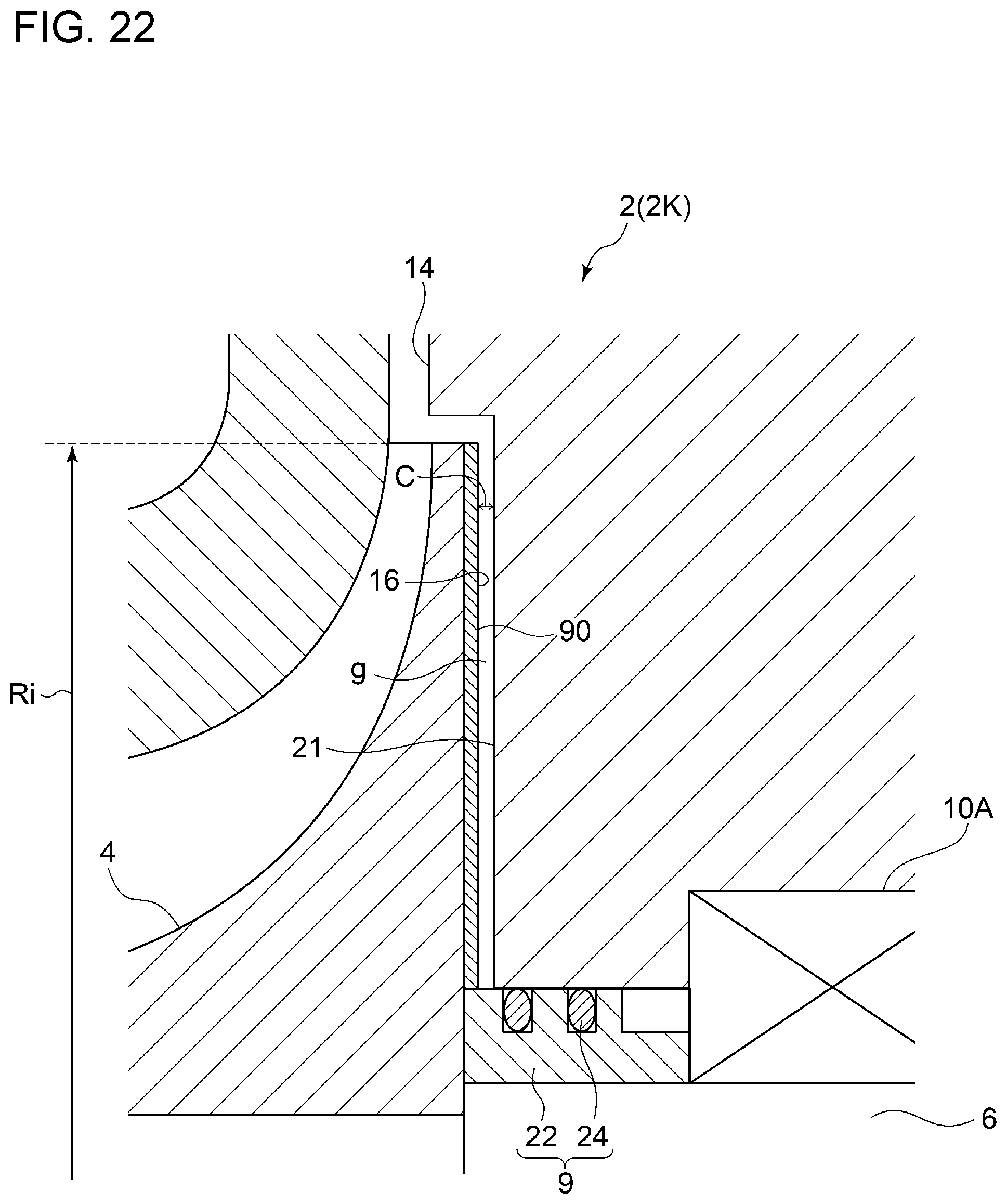
[0057] FIG. 22 is a schematic diagram showing a schematic cross-sectional view in the vicinity of a back surface 16 of a compressor impeller 4 of an electric supercharger 2 (2K) according to another embodiment.
[0058] FIG. 23 is a schematic configuration diagram of an engine device 100 to which an electric supercharger 2 (2A to 2K) can be applied.
DETAILED DESCRIPTION
[0059] Embodiments of the present invention will now be described in detail with reference to the accompanying drawings. It is intended, however, that unless particularly identified, dimensions, materials, shapes, relative positions and the like of components described in the embodiments shall be interpreted as illustrative only and not intended to limit the scope of the present invention.
[0060] For instance, an expression of relative or absolute arrangement such as "in a direction", "along a direction", "parallel", "orthogonal", "centered", "concentric" and "coaxial" shall not be construed as indicating only the arrangement in a strict literal sense, but also includes a state where the arrangement is relatively displaced by a tolerance, or by an angle or a distance whereby it is possible to achieve the same function.
[0061] For instance, an expression of an equal state such as "same" "equal" and "uniform" shall not be construed as indicating only the state in which the feature is strictly equal, but also includes a state in which there is a tolerance or a difference that can still achieve the same function.
[0062] Further, for instance, an expression of a shape such as a rectangular shape or a cylindrical shape shall not be construed as only the geometrically strict shape, but also includes a shape with unevenness or chamfered corners within the range in which the same effect can be achieved.
[0063] On the other hand, an expression such as "comprise", "include", "have", "contain" and "constitute" are not intended to be exclusive of other components.
[0064] FIG. 1 is a schematic diagram showing a schematic cross-sectional view of an electric supercharger 2 according to an embodiment.
[0065] In an illustrative embodiment depicted in FIG. 1, the electric supercharger 2 includes a compressor impeller 4, a rotational shaft 6, an impeller casing 8, bearings 10A, 10B, a motor 12, a back-surface side casing 14 (stationary member), and a mechanical seal 20.
[0066] Hereinafter, unless otherwise stated, the circumferential direction of the compressor impeller 4 is referred to as merely "circumferential direction", the radial direction of the compressor impeller 4 is referred to as merely "radial direction", and the axial direction of the compressor impeller 4 is referred to as merely "axial direction".
[0067] The impeller casing 8 is formed so as to surround the compressor impeller 4, and is configured to guide intake air to the inlet of the compressor impeller 4 and discharge air compressed by the compressor impeller 4.
[0068] The bearings 10A, 10B are configured as ball bearings that support the rotational shaft 6 rotatably, and as grease-lubrication type bearings which contain grease as a lubricating agent sealed around balls held between an inner race and an outer race which are not depicted. The bearing 10A is positioned between the mechanical seal 20 and the motor 12 in the axial direction, and is positioned between the back-surface side casing 14 and the rotational shaft 6 in the radial direction. The bearing 10B is positioned opposite to the bearing 10A across the motor 12 in the axial direction, and is positioned between the back-surface side casing 14 and the rotational shaft 6 in the radial direction.
[0069] The motor 12 is configured to transmit a driving force to the compressor impeller 4 via the rotational shaft 6. The motor 12 is positioned between the bearing 10A and the bearing 10B in the axial direction.
[0070] The back-surface side casing 14 faces the back surface 16 of the compressor impeller 4 via a gap, and is configured to surround the mechanical seal 20, the bearings 10A, 10B, and the motor 12. Further, the back-surface side casing 14 includes an inverter housing portion 18 for housing an inverter (not depicted), on the opposite side from the motor 12 across the bearing 10B.
[0071] The mechanical seal 20 is positioned between the back surface 16 of the compressor impeller 4 and the bearing 10A in the axial direction, and is configured to seal the gap between the rotational shaft 6 and the back-surface side casing 14.
[0072] FIG. 2 is a schematic diagram showing a schematic cross-sectional view in the vicinity of a back surface 16 of a compressor impeller 4 of an electric supercharger 2 (2A) according to an embodiment, showing a configuration example of a mechanical seal 20. FIG. 3 is a view of a compressor impeller 4 in rotation, in the electric supercharger 2 (2A) depicted in FIG. 2.
[0073] In some embodiments, as depicted in FIGS. 2 and 3, the mechanical seal 20 includes a stationary ring 22, a rotary ring 24, and a biasing member 26.
[0074] The stationary ring 22 is formed to have an annular shape along the circumferential direction, and is supported on the back-surface side casing 14. The stationary ring 22 is at a position that is between the rotary ring 24 and the back-surface side casing 14, and between the back-surface side casing 14 and the rotational shaft 6.
[0075] The rotary ring 24 is disposed between the back surface 16 of the compressor impeller 4 and the stationary ring 22, and is configured to have an annular shape along the circumferential direction so as to face the stationary ring 22 so as to be capable of being in contact with the stationary ring 22. The rotary ring 24 is configured to protrude toward an outer side from the rotational shaft 6 in the radial direction, and rotate together with the rotational shaft 6.
[0076] The biasing member 26 is configured to bias one of the stationary ring 22 or the rotary ring 24 toward the other one of the stationary ring 22 or the rotary ring 24. In the depicted embodiment, the biasing member 26 includes an elastic member (e.g., coil spring, disc spring, or rubber), and is interposed between the stationary ring 22 and the back-surface side casing 14 so as to bias the stationary ring 22 toward the rotary ring 24.
[0077] Furthermore, a groove 34 is formed on a facing surface 32, which is one of a surface 28 of the rotary ring 24 that faces the stationary ring 22, or a surface 30 of the stationary ring 22 that faces the rotary ring 24 (in the depicted embodiment, the facing surface 32 is the surface 28 of the rotary ring 24 facing the stationary ring 22). As depicted in FIG. 2, the groove 34 on the facing surface 32 is formed so as to be in communication with a space 36 on the inner side of the facing surface 32 in the radial direction (space between the stationary ring 22 and the rotational shaft 6), and so as not to be in communication with the space 38 on the outer side of the facing surface 32 in the radial direction (of the back-surface gap `g` between the back surface 16 and the back-surface side casing 14, the outer portion of the stationary ring 22), in a state where the stationary ring 22 and the rotary ring 24 are in contact. That is, in a state where the stationary ring 22 and the rotary ring 24 are in contact, the groove 34 is disposed from a position on the inner side, in the radially direction, of the radially inner end 40 of the contact portion between the stationary ring 22 and the rotary ring 24 on the facing surface 32 to a position that does not reach the radially outer end 42 of the contact portion between the stationary ring 22 and the rotary ring 24, on the facing surface 32.
[0078] With the above configuration, when rotation of the compressor impeller 4 is stopped, as depicted in FIG. 2, as the biasing member 26 pushes the stationary ring 22 against the rotary ring 24, the mechanical seal 20 functions as a contact seal. Accordingly, it is possible to suppress entry of a leakage flow from the back-surface gap `g` to the bearing 10A, and suppress inflow of the leakage flow into electric devices such as the motor 12. Thus, it is possible to suppress occurrence of malfunction or the like of the electric devices, and operate the electric supercharger stably.
[0079] Further, when the compressor impeller 4 is rotating, the pressure of gas inside the groove 34 having a pressure increased by a centrifugal force pushes the stationary ring 22 into the side of the biasing member 26, as depicted in FIG. 3. Accordingly, the stationary ring 22 and the rotary ring 24 separate from each other (not in contact). Nevertheless, with the pressure of the space 38 on the inner side of the facing surface 32 being higher than the pressure of the space 38 on the outer side of the facing surface 32, it is possible to suppress entry of a leakage flow from the back-surface gap `g` to the bearing 10A. Accordingly, it is possible to suppress inflow of the leakage flow into electric devices such as the motor 12. Thus, it is possible to suppress occurrence of malfunction or the like of the electric devices, and operate the electric supercharger stably.
[0080] Next, some modified examples of the electric supercharger 2 will be described with reference to FIGS. 4 to 13. In the following modified examples, the same configurations as those of the electric supercharger 2 (2A) are associated with the same reference numerals to omit description, and the characteristic configurations of the respective modified examples will be mainly described.
[0081] FIG. 4 is a schematic diagram showing a schematic cross-sectional view in the vicinity of a back surface 16 of a compressor impeller 4 of an electric supercharger 2 (2B) according to an embodiment. FIG. 5 is a diagram showing a configuration example of the ribs 44 depicted in FIG. 4, showing an example of arrangement of the ribs 44 in an axial-directional view. FIG. 6 is a diagram showing a configuration example of the ribs 44 depicted in FIG. 4, showing an example of arrangement of the ribs 44 in an axial-directional view.
[0082] In some embodiments, as depicted in FIGS. 4 to 6, a plurality of ribs 44 are disposed at intervals in the circumferential direction, on the back surface 16 of the compressor 4. With the above configuration, by providing the plurality of ribs 44, a centrifugal force toward the outer side in the radial direction is applied to air in the back-surface gap `g` upon rotation of the compressor impeller 4, and thereby it is possible to decrease the pressure of the radially inner part of the back-surface gap `g`. Accordingly, it is possible to suppress entry of a leakage flow from the back-surface gap `g` to the bearing 10A, and suppress inflow of the leakage flow into electric devices such as the motor. Further, by reducing the pressure of the radially inner part of the back-surface gap `g`, it is possible to decrease the spring force of the biasing member 26 required to move the stationary ring 22 appropriately, which makes it possible to suppress development of wear due to friction between the stationary ring 22 and the rotary ring 24.
[0083] In some embodiments, as shown in FIGS. 5 and 6 for instance, each of the ribs 44 is formed to extend along a direction that intersects with the circumferential direction. Further, in the embodiment depicted in FIG. 5, the plurality of ribs 44 are disposed so as to extend in a radial fashion along a direction orthogonal to the circumferential direction (radial direction).
[0084] With the above configuration, the plurality of ribs 44 extending in a direction orthogonal to the circumferential direction rotates with the compressor impeller 4, and thus it is possible to apply the centrifugal force toward the outer side in the radial direction effectively to air in the back-surface gap `g`, and reduce the pressure of the radially inner part of the back-surface gap `g`. Accordingly, it is possible to suppress entry of a leakage flow from the back-surface gap `g` to the bearing 10A, and suppress inflow of the leakage flow into electric devices such as the motor.
[0085] In some embodiments, as shown in FIG. 6, each of the ribs 44 has an airfoil shape. With the above configuration, it is possible to form an airflow toward the outer side in the radial direction effectively with the ribs 44 having an airfoil shape, in the back-surface gap `g` upon rotation of the compressor impeller 4. Accordingly, it is possible to suppress entry of a leakage flow from the back-surface gap `g` to the bearing 10A, and suppress inflow of the leakage flow into electric devices such as the motor 12.
[0086] In some embodiments, as depicted in FIG. 6 for instance, each rib 44 is disposed so as to extend in a direction inclined from the radial direction, such that the radially outer end 46 of the rib 44 is positioned on the upstream side of the radially inner end 48 of the rib 44, with respect to the rotational direction of the compressor impeller 4.
[0087] With the above configuration, with the ribs 44 being inclined in the above direction, it is possible to suppress inflow of air into the gaps between the ribs 44 from the outer side in the radial direction, during rotation of the compressor impeller 4. Accordingly, it is possible to suppress entry of a leakage flow from the back-surface gap `g` to the bearing 10A, and suppress inflow of the leakage flow into electric devices such as the motor 12.
[0088] FIG. 7 is a schematic diagram showing a schematic cross-sectional view in the vicinity of a back surface 16 of a compressor impeller 4 of an electric supercharger 2 (2C) according to an embodiment. FIG. 8 is a diagram showing a configuration example of the rotary part 50 depicted in FIG. 7, showing an example of the shape of the rotary part 50 in an axial-directional view. FIG. 9 is a diagram showing a configuration example of the rotary part 50 depicted in FIG. 7, showing an example of the shape of the rotary part 50 in an axial-directional view. FIG. 10 is a diagram showing a configuration example of the rotary part 50 depicted in FIG. 7, showing an example of the shape of the rotary part 50 in an axial-directional view.
[0089] In some embodiments, as depicted in FIG. 7, the electric supercharger further includes a rotary part 50 which protrudes outward in the radial direction from the rotational shaft 6, between the mechanical seal 20 and the back surface 16 of the compressor impeller 4, and which is configured to rotate together with the rotational shaft 6.
[0090] With the above configuration, a centrifugal force toward the outer side in the radial direction is applied to air in the back-surface gap `g` in accordance with rotation of the rotary part 50, and thereby it is possible to decrease the pressure of the radially inner part of the back-surface gap `g`. Accordingly, it is possible to suppress entry of a leakage flow from the back-surface gap `g` to the bearing 10A, and suppress inflow of the leakage flow into electric devices such as the motor 12. Further, by reducing the pressure of the radially inner part of the back-surface gap `g`, it is possible to decrease the spring force of the biasing member 26 required to move the stationary ring 22 appropriately, which makes it possible to suppress development of wear due to friction between the stationary ring 22 and the rotary ring 24.
[0091] The shape of the rotary part 50 is not particularly limited. For instance, the rotary part 51 may have an annular shape as depicted in FIG. 8, or may have a plurality of protrusions 52 (four protrusions 52 in the depicted embodiment) protruding outward in the radial direction from the annular shape as depicted in FIGS. 9 and 10. The protrusions 52 may protrude in a radial fashion along the radial direction as depicted in FIG. 9 for instance, or may have a tapered shape protruding diagonally with respect to the radial direction as depicted in FIG. 10.
[0092] FIG. 11 is a schematic diagram showing a schematic cross-sectional view in the vicinity of a back surface 16 of a compressor impeller 4 of an electric supercharger 2 (2D) according to an embodiment. FIG. 12 is a graph showing the relationship between the radial-directional position R and the gauge pressure P of the back-surface gap `g`. The dotted line indicates an electric supercharger 2 (2A) not including an abradable coating layer 90, and the solid line indicates an electric supercharger 2 (2D) including an abradable coating layer 90 formed on the facing surface 21. FIG. 13 is a schematic diagram showing a schematic cross-sectional view in the vicinity of a back surface 16 of a compressor impeller 4 of an electric supercharger 2 (2E) according to an embodiment.
[0093] In some embodiments, as depicted in FIG. 11, of the back-surface side casing 14, an abradable coating layer 90 is formed on at least a part of the facing surface 21 facing the back surface 16 of the compressor impeller 4 (the entire facing surface 21 in the depicted embodiment).
[0094] With the above configuration, the abradable coating layer 90 would be ground upon rotation of the compressor impeller 4 even if the abradable coating layer 90 formed on the facing surface 21 makes contact with the back surface 16 of the compressor impeller 4. Thus, it is possible to reduce the clearance C between the back surface 16 and the back-surface side casing 14 (distance between the back surface 16 and the back-surface side casing 14). Accordingly, it is possible to promote a pressure decrease toward the inner side in the radial direction, in the back-surface gap `g`, as described below.
[0095] FIG. 12 is a graph schematically showing the relationship between the radial-directional position R and the gauge pressure P of the back-surface gap `g`. The dotted line indicates an electric supercharger 2 (2A) not including an abradable coating layer 90, and the solid line indicates an electric supercharger 2 (2D) including an abradable coating layer 90 formed on the facing surface 21. Herein, the clearance C between the back surface 16 and the back-surface side casing 14 of the electric supercharger 2 (2D) is set to be smaller than the clearance between the back surface 16 and the back-surface side casing 14 of the electric supercharger 2 (2A).
[0096] As depicted in FIG. 12, in both of the electric supercharger 2 (2A) and the electric supercharger 2 (2D), the pressure decreases in the back-surface gap g, toward the inner side in the radial direction. Particularly in a region where the radial-directional position R is small, the pressure in the back-surface gap `g` in the electric supercharger 2(2D) is reduced considerably compared to that in the electric supercharger 2 (2A).
[0097] Accordingly, with the electric supercharger 2, by promoting the pressure decrease toward the inner side in the radial direction in the back-surface gap `g`, it is possible to reduce the axial-directional pressure difference between the pressure of the radially inner part (pressure near the mechanical seal 20) of the back-surface gap `g` and the pressure near the bearing 10A and thus it is possible to suppress entry of a leakage flow toward the bearing 10A (toward the mechanical seal 20) from the back-surface gap `g`. Accordingly, it is possible to suppress inflow of the leakage flow into electric devices such as the motor 12 and an inverter (not depicted). Thus, it is possible to suppress occurrence of malfunction or the like of the electric devices, and operate the electric supercharger 2 stably.
[0098] Further, the compressor impeller 4 receives a thrust force toward the upstream in the intake direction of air (left side in the drawing), in the axial direction, when air is compressed. In the above electric supercharger 2, it is possible to reduce the pressure in the back-surface gap `g` for the compressor impeller 4, and thus it is possible to reduce the thrust force in the axial direction.
[0099] Further, by promoting the pressure decrease toward the inner side in the radial direction in the back-surface gap `g` to reduce the pressure of the radially inner part of the back-surface gap `g`, it is possible to decrease the spring force of the biasing member 26 required to move the stationary ring 22 appropriately, which makes it possible to suppress development of wear due to friction between the stationary ring 22 and the rotary ring 24.
[0100] In an embodiment, in FIG. 11, the ratio C/Ri of the clearance C between the back surface 16 of the compressor impeller 4 and the back-surface side casing 14 to the outer diameter Ri of the compressor impeller 4 is less than 0.5%.
[0101] With the above configuration, it is possible to promote a pressure decrease toward the inner side in the radial direction, in the back-surface gap `g`, effectively. According to the inventors of the present invention, when comparing a case where the abradable coating layer 90 is provided and the ratio C/Ri is set to be 0.8% and a case where the abradable coating layer 90 is not provided and C/Ri is set to be 0.25%, the former can reduce more pressure of the radially inner part of the back-surface gap `g` by 26% compared to the latter.
[0102] In an embodiment, as depicted in FIG. 13, the abradable coating layer 90 is formed on at least a part of the back surface 16 of the compressor impeller 4. Furthermore, the ratio C/Ri of the clearance C between the back surface 16 of the compressor impeller 4 and the back-surface side casing 14 to the outer diameter Ri of the compressor impeller 4 is less than 0.5%.
[0103] With the above configuration, the abradable coating layer 90 would be ground upon rotation of the compressor impeller 4 even if the abradable coating layer 90 formed on the back surface 16 of the compressor impeller 4 makes contact with the facing surface 21 of the back-surface side casing 14. Thus, it is possible to reduce the clearance C between the back surface 16 and the back-surface side casing 14. Accordingly, it is possible to promote a pressure decrease toward the inner side in the radial direction, in the back-surface gap `g`.
[0104] Thus, it is possible to reduce the axial-directional pressure difference between the pressure of the radially inner part of the back-surface gap `g` (pressure near the mechanical seal 20) and the pressure near the bearing 10A, and thus it is possible to suppress entry of a leakage flow toward the bearing 10A (toward the mechanical seal 20) from the back-surface gap `g`. Accordingly, it is possible to suppress inflow of the leakage flow into electric devices such as the motor 12 and an inverter (not depicted). Thus, it is possible to suppress occurrence of malfunction or the like of the electric devices, and operate the electric supercharger stably.
[0105] Further, it is possible to reduce the pressure of the back-surface gap `g` by reducing the clearance C, and thus it is possible to reduce the thrust force in the axial direction in the compressor impeller 4.
[0106] Further, by promoting the pressure decrease toward the inner side in the radial direction in the back-surface gap `g` to reduce the pressure of the radially inner part of the back-surface gap `g`, it is possible to decrease the spring force of the biasing member 26 required to move the stationary ring 22 appropriately, which makes it possible to suppress development of wear due to friction between the stationary ring 22 and the rotary ring 24.
[0107] In some embodiments, as depicted in FIGS. 14 and 15 for instance, the electric supercharger 2 (2A to 2E) further includes a communication hole 53 serving as an internal-pressure adjustment mechanism, configured to adjust the pressure inside the back-surface side casing 14 by bringing the inside and the outside of the back-surface side casing 14 into communication. The communication hole 53 may be disposed on the compressor side of the back-surface side casing 14 as depicted in FIG. 14, or on the inverter side as depicted in FIG. 15, or on both sides. The position, shape, and dimension like hole diameter of the communication hole 53 are to be designed to be optimum in accordance with the size of the electric supercharger 2. Further, in the embodiment depicted in FIGS. 14 and 15, on the outer end portion side of the communication hole 53, a waterproof ventilation filter 55 is disposed, which protects the inside of the back-surface side casing 14 from dust, water, oil, and the like while adjusting the pressure and the temperature inside the back-surface side casing 14.
[0108] With the above configuration, even in a case where the pressure of the radially inner part of the back-surface gap `g` is low, it is possible to stabilize the pressure balance across the mechanical seal 20 by adjusting the pressure inside and outside the back-surface side casing 14 through the communication hole 53. Accordingly, it is possible to suppress entry of a leakage flow to the bearings 10A, 10B through the back-surface gap `g` stably with the mechanical seal 20.
[0109] FIG. 16 is a schematic configuration diagram of an engine device 100 to which the above described electric supercharger 2 (2A to 2E) can be applied preferably. FIG. 16 is a diagram of an embodiment of an engine device 100 in a case where the electric supercharger 2 is used as a high-pressure stage supercharger of a two-stage supercharging system.
[0110] The engine device 100 depicted in FIG. 16 includes, as depicted in the drawing, an engine 54, an intake passage 56 through which intake gas to be supplied to the engine 54 flows, an exhaust passage 58 through which exhaust gas discharged from the engine 54 flows, a turbocharger 60, and the above described electric supercharger 2.
[0111] The turbocharger 60 includes an exhaust turbine 64 disposed in the exhaust passage 58, a compressor 62 disposed in the intake passage 56, and an exhaust turbine shaft 63 coupling the exhaust turbine 64 and the compressor 62. The turbocharger 60 is configured such that the exhaust turbine 64 is driven by exhaust gas discharged from the engine 54, and thereby the compressor 62 is coaxially driven via the turbine shaft 63, so as to supercharge intake gas flowing through the intake passage 56.
[0112] The electric supercharger 2 is disposed on the downstream side of the compressor 62 in the intake passage 56, and intake gas compressed by the compressor 62 of the turbocharger 60 is supplied to the compressor impeller 4 of the electric supercharger 2. As described above, the engine device 100 of the present embodiment is configured as a two-stage supercharging system in which the turbocharger 60 is provided as a low-pressure stage supercharger and the electric supercharger 2 is provided as a high-pressure stage supercharger.
[0113] A bypass intake passage 66 bypassing the electric supercharger 2 is connected to the intake passage 56. A bypass valve 68 is disposed in the bypass intake passage 66. Further, by adjusting the valve opening degree of the bypass valve 68, the flow rate of intake gas flowing into the electric supercharger 2 is controlled.
[0114] Further, on the downstream side of the electric supercharger 2 in the intake passage 56, an intermediate cooler 70 for cooling intake gas to be supplied to the engine 54 is disposed.
[0115] Furthermore, the engine device 100 includes an EGR passage 72 that connects the downstream side of the exhaust turbine 64 in the exhaust passage 58 and the upstream side of the compressor 62 in the intake passage 56. An EGR valve 74 is disposed in the EGR passage 72. Further, by adjusting the valve opening degree of the EGR valve 74, exhaust gas having a flow rate corresponding to the valve opening degree returns to the intake passage 56. Further, intake gas containing the recirculated exhaust gas is supplied to the compressor impeller 4 of the electric supercharger 2.
[0116] In the above engine device 100, the bypass valve 68 is closed when the engine rotates at a low speed. The intake gas pressurized by the turbocharger 60 serving as a low-pressure stage supercharger is supplied to the electric supercharger 2 serving as a high-pressure stage supercharger as indicated by the arrow `a`, to be pressurized further. Thus, compared to a case where the electric supercharger 2 is disposed at the low-pressure stage, the differential pressure between the radially outer part and the radially inner part of the compressor in the electric supercharger 2 becomes high, and high-temperature and high-pressure intake air enters the above described back-surface gap `g`.
[0117] Furthermore, in the engine device 100, the bypass valve 68 is open and the electric supercharger 2 is stopped when the engine rotates at a high speed. In this case, the intake gas pressurized by the turbocharger 60 serving as a low-pressure stage supercharger is supplied to the downstream side of the electric supercharger 2 through the bypass intake passage 66, as indicated by the arrow `b`. Thus, the boost pressure of the turbocharger 60 creates a differential pressure between the radially outer part and the radially inner part of the compressor in the electric supercharger 2, and causes intake air to enter the above described back-surface gap `g`.
[0118] In this regard, by applying the above described electric supercharger 2 (2A to 2E) to the engine device 100, it is possible to suppress entry of high-temperature and high-pressure intake air to the bearing side via the back-surface gap `g`, and thus it is possible to suppress occurrence of troubles in devices such as the bearings 10A, 10B and the motor 12, effectively.
[0119] Furthermore, normally, in a case where a part of exhaust gas is recirculated to the upstream side of the low-pressure stage supercharger by a two-stage supercharging system including the above described EGR passage, and a case where an intermediate cooler is used, and a case where blow-by gas is returned to the inlet of the electric supercharger, for instance, air containing condensed water is taken in from the inlet of the electric supercharger, and thus a leakage flow passing through the back-surface gap and entering the bearing side is likely to cause trouble in operation of devices such as the motor and the inverter.
[0120] In this regard, by applying the above described electric supercharger 2 (2A to 2E) to the engine device 100, it is possible to suppress entry of high-temperature and high-pressure intake air to the bearing side via the back-surface gap `g`, and thus it is possible to suppress occurrence of troubles in devices such as the bearings 10A, 10B and the motor 12, effectively.
[0121] Embodiments of the present invention were described in detail above, but the present invention is not limited thereto, and various amendments and modifications may be implemented.
[0122] For instance, in the above described embodiments, the back-surface side casing 14 surrounds the mechanical seal 20, the bearings 10A, 10B, and the motor 12. Nevertheless, the configuration of the back-surface side casing 14 is not limited to this. For instance, the back-surface side casing 14 may surround only the mechanical seal 20, and a casing other than the back-surface side casing 14 may surround the bearings 10A, 10B and the motor 12. Alternatively, the back-surface side casing 14 may surround only the mechanical seal 20 and the bearing 10A, and a casing other than the back-surface side casing 14 may surround the bearing 10B and the motor 12.
[0123] Furthermore, while the above described electric supercharger 2 (2A to 2E) includes the mechanical seal 20, the electric supercharger 2 may not necessarily include the mechanical seal 20 in another embodiment.
[0124] FIG. 17 is a schematic diagram showing a schematic cross-sectional view in the vicinity of a back surface 16 of a compressor impeller 4 of an electric supercharger 2 (2F) according to another embodiment. FIG. 18 is a schematic diagram showing a schematic cross-sectional view in the vicinity of a back surface 16 of a compressor impeller 4 of an electric supercharger 2 (2G) according to another embodiment. FIG. 19 is a schematic diagram showing a schematic cross-sectional view in the vicinity of a back surface 16 of a compressor impeller 4 of an electric supercharger 2 (2H) according to another embodiment. FIG. 20 is a schematic diagram showing a schematic cross-sectional view in the vicinity of a back surface 16 of a compressor impeller 4 of an electric supercharger 2 (2I) according to another embodiment. FIG. 21 is a schematic diagram showing a schematic cross-sectional view in the vicinity of a back surface 16 of a compressor impeller 4 of an electric supercharger 2 (2J) according to another embodiment. FIG. 22 is a schematic diagram showing a schematic cross-sectional view in the vicinity of a back surface 16 of a compressor impeller 4 of an electric supercharger 2 (2K) according to another embodiment.
[0125] The basic configuration of the electric supercharger 2 (2F to 2K) is similar to that of the electric supercharger 2 depicted in FIG. 1, except that the mechanical seal 20 is not provided. Thus, the same configurations are associated with the same reference numerals to omit description, and the characteristic configurations of the respective modified examples will be mainly described.
[0126] In some embodiments depicted in FIGS. 17 to 19, the electric supercharger 2 (2F to 2H) further includes a rotary part 76 which protrudes outward in the radial direction from the rotational shaft 6, between the back-surface side casing 14 and the back surface 16 of the compressor impeller 4, and which is configured to rotate together with the rotational shaft 6. Further, the radially outer end 78 of the rotary part 76 is positioned on the outer side of the radially inner end 80 of the back-surface side casing 14 in the radial direction.
[0127] Although the shape of the rotary part 76 is not particularly limited, the respective shapes of the rotary part 50 described with reference to FIGS. 8 to 10 may be applied. Furthermore, the rotary part 76 may be disposed at a distance from the back surface 16 of the compressor impeller 4 as depicted in FIG. 17, or in contact with the back surface 16 of the compressor impeller 4 as depicted in FIGS. 18 and 19, or integrally with the compressor impeller 4 or a non-depicted sleeve engaged with the rotational shaft 6. Further, as depicted in FIGS. 18 and 19, the rotary part 76 may protrude toward the back surface 16 past the facing surface 21 of the back-surface side casing 14 that faces the back surface 16. Furthermore, in a case where a recessed portion 82 is formed on the back surface 16 of the compressor impeller 4, the rotary part 76 may include a protruding portion 84 protruding in the axial direction so as to enter the inside of the recessed portion 82 as depicted in FIG. 19.
[0128] In the embodiment depicted in FIG. 20, the electric supercharger 2 (2I) includes a seal unit 9 instead of the mechanical seal 20 of the electric supercharger 2 (2B) depicted in FIG. 4. In the electric supercharger 2 (2I), similarly to the electric supercharger 2 (2B), a plurality of ribs 44 are disposed at intervals in the circumferential direction, on the back surface 16 of the compressor 4.
[0129] Furthermore, the seal unit 9 includes a sleeve 86 and at least one piston ring 88 (in the depicted embodiment, two piston rings 88). The sleeve 86 is disposed such that an end side of the sleeve 86 is in contact with the back surface 16 of the compressor impeller 4, in a state where the sleeve 86 is engaged with the rotational shaft 6. The piston ring 88 is engaged with an annular groove disposed on the outer peripheral surface of the sleeve 86 and is in contact with the back-surface side casing 14, thereby sealing the gap between the rotational shaft 6 and the back-surface side casing 14.
[0130] Also with the above configuration, by providing the plurality of ribs 44, a centrifugal force toward the outer side in the radial direction is applied to air in the back-surface gap `g` upon rotation of the compressor impeller 4, and thereby it is possible to decrease the pressure of the radially inner part of the back-surface gap `g`. Accordingly, it is possible to suppress entry of a leakage flow from the back-surface gap `g` to the bearing 10A, and suppress inflow of the leakage flow into electric devices such as the motor.
[0131] In the embodiment depicted in FIG. 21, the electric supercharger 2 (2J) includes a seal unit 9 instead of the mechanical seal 20 of the electric supercharger 2 (2D) depicted in FIG. 11. In the electric supercharger 2 (2J), similarly to the electric supercharger 2 (2D), of the back-surface side casing 14, an abradable coating layer 90 is formed on at least a part of the facing surface 21 facing the back surface 16 of the compressor impeller 4 (the entire facing surface 21 in the depicted embodiment).
[0132] Also with the above configuration, by promoting the pressure decrease toward the inner side in the radial direction in the back-surface gap `g`, it is possible to reduce the axial-directional pressure difference between the pressure of the radially inner part of the back-surface gap `g` (pressure near the seal unit 9) and the pressure near the bearing 10A and thus it is possible to suppress entry of a leakage flow toward the bearing 10A (toward the seal unit 9) from the back-surface gap `g`. Accordingly, it is possible to suppress inflow of the leakage flow into electric devices such as the motor 12 and an inverter (not depicted). Thus, it is possible to suppress occurrence of malfunction or the like of the electric devices, and operate the electric supercharger 2 stably.
[0133] Further, the compressor impeller 4 receives a thrust force toward the upstream in the intake direction of air (left side in the drawing), in the axial direction, when air is compressed. In the above electric supercharger 2 (2J), it is possible to reduce the pressure in the back-surface gap `g` for the compressor impeller 4, and thus it is possible to reduce the thrust force in the axial direction.
[0134] In the embodiment depicted in FIG. 22, the electric supercharger 2 (2K) includes a seal unit 9 instead of the mechanical seal 20 of the electric supercharger 2 (2E) depicted in FIG. 13. In the electric supercharger 2 (2K), similarly to the electric supercharger 2 (2E), the abradable coating layer 90 is formed on at least a part of the back surface 16 of the compressor impeller 4.
[0135] Also with the above configuration, by promoting the pressure decrease toward the inner side in the radial direction in the back-surface gap `g`, it is possible to reduce the axial-directional pressure difference between the pressure of the radially inner part of the back-surface gap `g` (pressure near the seal unit 9) and the pressure near the bearing 10A and thus it is possible to suppress entry of a leakage flow toward the bearing 10A (toward the seal unit 9) from the back-surface gap `g`.
[0136] Further, the compressor impeller 4 receives a thrust force toward the upstream in the intake direction of air (left side in the drawing), in the axial direction, when air is compressed. In the above electric supercharger 2 (2K), it is possible to reduce the pressure in the back-surface gap `g` for the compressor impeller 4, and thus it is possible to reduce the thrust force in the axial direction.
[0137] Further, while the electric supercharger 2 (2A to 2E) is described as preferably applicable as a high-pressure stage supercharger of a two-stage supercharging system in the embodiment depicted in FIG. 16, the electric supercharger 2 (2A to 2K) may be used as a low-pressure stage supercharger of a two-stage supercharging system as depicted in FIG. 23.
[0138] Hereinafter, the engine device 110 depicted in FIG. 23 will be described. Of the configuration depicted in FIG. 23, the configurations similar to those depicted in FIG. 16 is associated with the same reference numerals to omit description, and what is different from the configuration depicted in FIG. 16 will be mainly described.
[0139] In the engine device 100 depicted in FIG. 23, the electric supercharger 2 is disposed on the upstream side of the compressor 62 in the intake passage 56, and intake gas compressed by the electric supercharger 2 is supplied to the compressor 62 of the turbocharger 60. As described above, the engine device 110 is configured as a two-stage supercharging system in which the turbocharger 60 is provided as a high-pressure stage supercharger and the electric supercharger 2 is provided as a low-pressure stage supercharger.
[0140] A bypass intake passage 66 bypassing the electric supercharger 2 is connected to the intake passage 56. A bypass valve 68 is disposed in the bypass intake passage 66. Further, by adjusting the valve opening degree of the bypass valve 68, the flow rate of intake gas flowing into the electric supercharger 2 is controlled.
[0141] Further, on the downstream side of the compressor 62 in the intake passage 56, an intermediate cooler 70 for cooling intake gas to be supplied to the engine 54 is disposed.
[0142] Furthermore, the engine device 110 includes an EGR passage 72 that connects the downstream side of the exhaust turbine 64 in the exhaust passage 58 and the upstream side of the electric supercharger 2 in the intake passage 56. An EGR valve 74 is disposed in the EGR passage 72. Further, by adjusting the valve opening degree of the EGR valve 74, exhaust gas having a flow rate corresponding to the valve opening degree returns to the intake passage 56. Further, intake gas containing the recirculated exhaust gas is supplied to the compressor impeller 4 of the electric supercharger 2.
[0143] In the above engine device 110, the bypass valve 68 is closed when the engine rotates at a low speed. The intake gas pressurized by the electric supercharger 2 serving as a low-pressure stage supercharger is supplied to the compressor 62 of the turbocharger 60 serving as a high-pressure stage supercharger as indicated by the arrow `c`, to be pressurized further. Thus, the boost pressure of the electric supercharger 2 is applied to the gap between the radially outer part and the radially inner part of the compressor in the electric supercharger 2, and causes intake air to enter the above described back-surface gap `g`.
[0144] Furthermore, in the engine device 110, the bypass valve 68 is open and the electric supercharger 2 is stopped when the engine rotates at a high speed. In this case, as indicated by the arrow `d`, intake gas is supplied to the compressor 62 through the bypass intake passage 66, and thus substantially no intake air enters the back-surface gap `g` of the electric supercharger 2.
[0145] As described above, by applying the above described electric supercharger 2 (2A to 2K) to the engine device 110, it is possible to suppress entry of high-temperature and high-pressure intake air to the bearing side via the back-surface gap `g`, and thus it is possible to suppress occurrence of troubles in devices such as the bearings 10A, 10B and the motor 12, effectively.
REFERENCE SIGNS LIST
[0146] 2 (2A to 2K) Supercharger [0147] 4 Compressor impeller [0148] 6 Rotational shaft [0149] 8 Impeller casing [0150] 9 Seal unit [0151] 10A, 10B Bearing [0152] 12 Motor [0153] 14 Back-surface side casing [0154] 16 Back surface [0155] 18 Inverter housing portion [0156] 20 Mechanical seal [0157] 21, 32 Facing surface [0158] 22 Stationary ring [0159] 24 Rotary ring [0160] 26 Biasing member [0161] 28, 30 Surface [0162] 34 Groove [0163] 36, 38 Space [0164] 40, 48, 80 Radially inner end [0165] 42, 46, 78 Radially outer end [0166] 44 Rib [0167] 50, 76 Rotary part [0168] 52 Protrusion [0169] 53 Communication hole [0170] 54 Engine [0171] 55 Waterproof ventilation filter [0172] 56 Intake passage [0173] 58 Exhaust passage [0174] 60 Turbocharger [0175] 62 Compressor [0176] 63 Turbine shaft [0177] 64 Exhaust turbine [0178] 66 Bypass intake passage [0179] 68 Bypass valve [0180] 70 Intermediate cooler [0181] 72 Passage [0182] 74 Valve [0183] 82 Recessed portion [0184] 84 Protruding portion [0185] 86 Sleeve [0186] 88 Piston ring [0187] 90 Abradable coating layer [0188] 100, 110 Engine device
* * * * *
D00000
D00001
D00002
D00003
D00004
D00005
D00006
D00007
D00008
D00009
D00010
D00011
D00012

D00013

D00014

D00015

D00016

D00017

D00018

D00019

D00020
D00021

XML
uspto.report is an independent third-party trademark research tool that is not affiliated, endorsed, or sponsored by the United States Patent and Trademark Office (USPTO) or any other governmental organization. The information provided by uspto.report is based on publicly available data at the time of writing and is intended for informational purposes only.
While we strive to provide accurate and up-to-date information, we do not guarantee the accuracy, completeness, reliability, or suitability of the information displayed on this site. The use of this site is at your own risk. Any reliance you place on such information is therefore strictly at your own risk.
All official trademark data, including owner information, should be verified by visiting the official USPTO website at www.uspto.gov. This site is not intended to replace professional legal advice and should not be used as a substitute for consulting with a legal professional who is knowledgeable about trademark law.