Wear Resistant Insert
Leung; Philip Park-Hung
U.S. patent application number 16/960500 was filed with the patent office on 2020-12-03 for wear resistant insert. The applicant listed for this patent is Halliburton Energy Services, Inc.. Invention is credited to Philip Park-Hung Leung.
| Application Number | 20200378195 16/960500 |
| Document ID | / |
| Family ID | 1000005088682 |
| Filed Date | 2020-12-03 |


| United States Patent Application | 20200378195 |
| Kind Code | A1 |
| Leung; Philip Park-Hung | December 3, 2020 |
Wear Resistant Insert
Abstract
A wear resistant insert including a deposition substrate having an exterior surface, and a wear resistant layer deposited on the exterior surface of the deposition substrate. The wear resistant insert may further include a structure interface layer deposited on an exterior surface of the wear resistant layer. A method of forming a wear resistant insert including providing a deposition substrate having an exterior surface, and depositing a wear resistant layer on the exterior surface of the deposition substrate. The method may further include depositing a structure interface layer on an exterior surface of the wear resistant layer. The method may further include separating the wear resistant layer from the deposition substrate intact.
| Inventors: | Leung; Philip Park-Hung; (Edmonton, CA) | ||||||||||
| Applicant: |
|
||||||||||
|---|---|---|---|---|---|---|---|---|---|---|---|
| Family ID: | 1000005088682 | ||||||||||
| Appl. No.: | 16/960500 | ||||||||||
| Filed: | February 27, 2018 | ||||||||||
| PCT Filed: | February 27, 2018 | ||||||||||
| PCT NO: | PCT/CA2018/050226 | ||||||||||
| 371 Date: | July 7, 2020 |
| Current U.S. Class: | 1/1 |
| Current CPC Class: | E21B 17/1007 20130101; C23C 4/185 20130101; C23C 4/134 20160101; C23C 4/129 20160101; C23C 4/10 20130101; E21B 17/1078 20130101 |
| International Class: | E21B 17/10 20060101 E21B017/10; C23C 4/10 20060101 C23C004/10; C23C 4/134 20060101 C23C004/134; C23C 4/129 20060101 C23C004/129; C23C 4/18 20060101 C23C004/18 |
Claims
1. A wear resistant insert, comprising: (a) a deposition substrate having an exterior surface; and (b) a wear resistant layer comprising a wear resistant material deposited on the exterior surface of the deposition substrate.
2. The wear resistant insert as claimed in claim 1 wherein the wear resistant layer has an interior surface which defines a wear resistant bore of the wear resistant layer and wherein the wear resistant layer is separable from the deposition substrate intact in order to expose the wear resistant bore.
3. The wear resistant insert as claimed in claim 2 wherein the deposition substrate is destroyable while leaving the wear resistant layer intact so that the wear resistant layer is separable intact from the deposition substrate by destroying the deposition substrate.
4. The wear resistant insert as claimed in claim 3 wherein the deposition substrate is less wear resistant than the wear resistant layer so that the deposition substrate is destroyed by wearing of the deposition substrate.
5. The wear resistant insert as claimed in claim 3 wherein the deposition substrate is dissolvable without dissolving the wear resistant layer so that the deposition substrate is destroyed by dissolving the deposition substrate.
6. The wear resistant insert as claimed in claim 3 wherein the deposition substrate is meltable without melting the wear resistant layer so that the deposition substrate is destroyed by melting the deposition substrate.
7. The wear resistant insert as claimed in claim 2 wherein the wear resistant layer is deposited on the deposition substrate by immersion, electrodeposition, electroless deposition, welding, cladding, spraying, vapour deposition, additive manufacturing, or a combination thereof
8. The wear resistant insert as claimed in claim 2 wherein the wear resistant material is a non-metallic crystalline material, a carbide, a nitride, an alloy, or a combination thereof
9. The wear resistant insert as claimed in claim 2 wherein the deposition substrate is an elongated member and wherein the wear resistant layer is deposited on the exterior surface of the deposition substrate as an elongated tube.
10. The wear resistant insert as claimed in claim 9 wherein the deposition substrate defines a substrate bore extending longitudinally through the deposition substrate.
11. The wear resistant insert as claimed in claim 2 wherein the wear resistant layer has an exterior surface, further comprising a structure interface layer deposited on the exterior surface of the wear resistant layer.
12. The wear resistant insert as claimed in claim 11 wherein the structure interface layer is machinable.
13. The wear resistant insert as claimed in claim 11 wherein the structure interface layer is non-porous.
14. A method of forming a wear resistant insert, comprising: (a) providing a deposition substrate, wherein the deposition substrate has an exterior surface; and (b) depositing a wear resistant layer on the exterior surface of the deposition substrate, wherein the wear resistant layer comprises a wear resistant material.
15. The method as claimed in claim 14 wherein depositing the wear resistant layer on the exterior surface of the deposition substrate comprises depositing the wear resistant layer by immersion, electrodeposition, electroless deposition, welding, cladding, spraying, vapour deposition, additive manufacturing, or a combination thereof
16. The method as claimed in claim 14 wherein the wear resistant material is a non-metallic crystalline material, a carbide, a nitride, an alloy, or a combination thereof
17. The method as claimed in claim 14, further comprising separating the wear resistant layer from the deposition substrate intact.
18. The method as claimed in claim 14 wherein the wear resistant layer has an exterior surface, further comprising depositing a structure interface layer on the exterior surface of the wear resistant layer.
19. The method as claimed in claim 18, further comprising providing at least one hole, slot or groove in the structure interface layer.
20. The method as claimed in claim 19 wherein providing at least one hole, slot or groove in the structure interface layer comprises machining the structure interface layer.
21. The method as claimed in claim 14, further comprising installing the wear resistant insert in an interior space of a structure.
22. The method as claimed in claim 21, further comprising separating the wear resistant layer from the deposition substrate intact after installing the wear resistant insert in the interior space of the structure.
23. The method as claimed in claim 22 wherein separating the wear resistant layer from the deposition substrate intact comprises destroying the deposition substrate.
24. The method as claimed in claim 22 wherein the deposition substrate is an elongated member, wherein the interior space of the structure is a bore defined by the structure, and wherein installing the wear resistant insert in the interior space of the structure comprises inserting the wear resistant insert in the bore of the structure.
25. The method as claimed in claim 24, further comprising fastening the wear resistant insert to the structure after the wear resistant insert has been inserted in the bore of the structure.
26. The method as claimed in claim 24 wherein the deposition substrate defines a substrate bore extending longitudinally through the deposition substrate and wherein separating the wear resistant layer from the deposition substrate intact comprises passing a fluid through the substrate bore in order to destroy the deposition substrate.
27. The method as claimed in claim 24 wherein the structure is a structure for use in a borehole.
28. The method as claimed in claim 24 wherein the structure is a drilling motor for use in drilling a borehole.
Description
TECHNICAL FIELD
[0001] A wear resistant insert, a method of forming a wear resistant insert, and a method of installing a wear resistant insert in or on a structure.
BACKGROUND OF THE INVENTION
[0002] The surfaces of a tool or other structure may be susceptible to wear during use. Such wear may have various causes, including but not limited to friction, abrasion, erosion, corrosion, impacts, and/or fatigue. Increasing the wear resistance of an interior surface of a tool or other structure may be challenging due to line of sight limitations, access limitations, space limitations due to small component dimensions (including as a non-limiting example within small bores), material incompatibilities, and/or other limitations. In the oil and gas industry, the interior surfaces of tools and other non-tubular or tubular structures may be susceptible to wear as a result of the environments in which the structures are used and the conditions to which the structures are exposed.
BRIEF DESCRIPTION OF DRAWINGS
[0003] Embodiments of the invention will now be described with reference to the accompanying drawings, in which:
[0004] FIG. 1 is a schematic view of portions of a drilling motor for use in drilling a borehole.
[0005] FIG. 2 is a schematic pictorial view of a first non-limiting embodiment of a wear resistant insert.
[0006] FIG. 3 is a schematic pictorial view of a second non-limiting embodiment of a wear resistant insert.
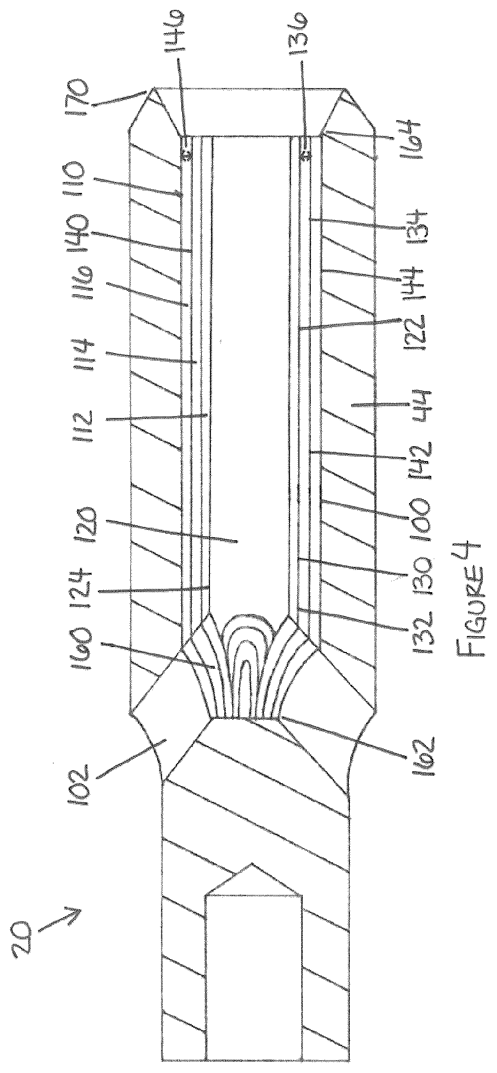
[0007] FIG. 4 is a longitudinal cross-sectional view depicting a third non-limiting embodiment of a wear resistant insert installed in a drilling motor of the general type depicted in FIG. 1.
DETAILED DESCRIPTION
[0008] This description is directed, in part, to a wear resistant insert, to a method of forming a wear resistant insert, and to a method of installing a wear resistant insert in or on a structure.
[0009] The wear resistant insert described herein may be used in any environment and/or with any structure in which wear resistance is desired. The wear resistance which is provided by the wear resistant insert may be resistance to any cause of wear, including as non-limiting examples, wear by friction, abrasion, erosion, corrosion, impacts, and/or fatigue.
[0010] The wear resistant insert described herein may be particularly suited for providing wear resistance to a structure in which it may be difficult or impossible to apply or provide wear resistance to the structure directly because of line of sight limitations, access limitations, space limitations due to small component dimensions (including as a non-limiting example within small bores), material incompatibilities, and/or other limitations, and/or where the heat required to apply or provide wear resistance to the structure may degrade or otherwise adversely affect the material properties of the material or materials from which the structure is formed.
[0011] As a non-limiting example, the wear resistant insert described herein may be used to provide wear resistance to an interior space of a structure. A structure having an interior space may be a non-tubular structure or a tubular structure, and may fully or partially define and/or enclose the interior space. Both a non-tubular structure and a tubular structure may have any shape and may fully or partially define and/or enclose an interior space having any shape. As a non-limiting example, a tubular structure may define a longitudinal axis and/or may be elongated, a tubular structure may have a round, oval, polygonal or any other suitable cross-sectional shape, and a tubular structure may define and/or enclose an interior space having a round, oval, polygonal or any other suitable cross-sectional shape.
[0012] As a non-limiting example, the structure may be a non-tubular or tubular housing having an interior space which contains moving parts and which may therefore be particularly susceptible to wear by friction, abrasion, erosion, corrosion, impacts, and/or fatigue. As a non-limiting example, the structure may be a tubular structure which contains or transports a fluid, including but not limited to a pipe, a conduit, or a trough and which may therefore be particularly susceptible to wear by abrasion, erosion and/or corrosion.
[0013] As a non-limiting example, the wear resistant insert described herein may be used with a structure which is suitable to be inserted and used within a borehole. As a non-limiting example, the structure may be a non-tubular or tubular tool or other structure for use in drilling a borehole. As a non-limiting example, such a tool or other structure may be a component of a drilling string. As non-limiting examples, such a tool or other structure may comprise, consist of, or consist essentially of a drill pipe, a drill collar, a drilling tool, a logging tool, a measuring tool, a communication tool, a reamer, a stabilizer, and/or a drill bit. Non-limiting examples of a drilling tool include a drilling motor, a rotary steerable drilling apparatus, a turbine, a reciprocating hammer, or any other apparatus which is suitable for use in drilling a borehole.
[0014] The wear resistant insert comprises a wear resistant layer. The wear resistant layer comprises a wear resistant material. The wear resistant insert may comprise a deposition substrate having an exterior surface. The wear resistant layer may be deposited on the exterior surface of the deposition substrate. Alternatively, the wear resistant insert may not comprise a deposition substrate, and the wear resistant layer may be deposited independently in a desired shape.
[0015] The deposition substrate supports the wear resistant layer during the deposition of the wear resistant layer. The deposition substrate may also support the wear resistant layer during storage, handling, and/or installation of the wear resistant insert. If such support is not required, the deposition substrate may in some circumstances be omitted from the wear resistant insert.
[0016] The deposition substrate may have any shape which is suitable for the intended use of the wear resistant insert, including the size, dimensions, and configuration of the structure with which it is used. As non-limiting examples, the deposition substrate may have essentially a two-dimensional (eg., planar) shape or the deposition substrate may have a three-dimensional shape.
[0017] If the deposition substrate has essentially a two-dimensional shape, the two-dimensional shape may have two opposing faces and a perimeter having any suitable perimeter shape, including but not limited to round, oval, polygonal, or a combination of such shapes. If the deposition substrate has a two-dimensional shape, the exterior surface of the deposition substrate may comprise one or both of the opposing faces and/or the perimeter of the deposition substrate.
[0018] If the deposition substrate has a three-dimensional shape, the three-dimensional shape may be any desired form. If the deposition substrate has a three-dimensional shape, the exterior surface of the deposition substrate may comprise the exterior of the deposition substrate. As a non-limiting example of a three-dimensional shape, the deposition substrate may comprise, consist of, or consist essentially of an elongated member. If the deposition substrate comprises, consists of, or consists essentially of an elongated member, the exterior surface of the elongated member may have any desired cross-sectional shape. As non-limiting examples, the exterior surface of the elongated member may be round, oval, polygonal, or a combination of such shapes.
[0019] The deposition substrate may define one or more holes, notches, slots, grooves, and/or bores. As a non-limiting example, the deposition substrate may define a substrate bore. The substrate bore may extend through the deposition substrate. If the deposition substrate comprises, consists of, or consists essentially of an elongated member, the substrate bore may extend longitudinally through the elongated member. Such holes, notches, slots, grooves, and/or bores may be formed in the deposition substrate during fabrication of the deposition substrate or after fabrication of the deposition substrate by machining or by some other suitable process.
[0020] The exterior surface of the deposition substrate may define one or more discontinuities including, as non-limiting examples, one or more protrusions, lugs, flanges, extensions, holes, notches, slots, grooves, and/or bores. The one or more discontinuities may define and/or influence the shape and/or configuration of the wear resistant layer which is deposited on the exterior surface of the deposition substrate, and/or may accommodate features of the structure with which the wear resistant insert is to be used. Such discontinuities may be formed in the deposition substrate during fabrication of the deposition substrate or after fabrication of the deposition substrate by machining or by some other suitable process.
[0021] The wear resistant layer may be deposited either directly or indirectly on the deposition substrate. The wear resistant layer is deposited directly on the deposition substrate if the wear resistant layer is in direct contact with the deposition substrate. The wear resistant layer is deposited indirectly on the deposition substrate if one or more intermediate materials or layers separate the wear resistant layer from the deposition substrate.
[0022] The wear resistant layer may be deposited on all or a portion of the exterior surface of the deposition substrate. The wear resistant layer may be deposited on the exterior surface of the deposition substrate in any suitable manner which is capable essentially of applying a coating of the wear resistant layer on all or a portion of the exterior surface of the deposition substrate. As non-limiting examples, the wear resistant layer may be deposited on the exterior surface of the deposition substrate by immersion, electrodeposition, electroless deposition, welding, cladding, spraying, vapour deposition, additive manufacturing, or a combination of such processes.
[0023] As a non-limiting example, immersion may comprise, consist of, or consist essentially of dipping and/or immersing the deposition substrate in a fluid bath. As non-limiting examples, electrodeposition may comprise, consist of, or consist essentially of electroplating and/or electrodeposition. As non-limiting examples, welding may comprise, consist of, or consist essentially of oxyacetylene welding, tungsten inert gas (TIG) welding, metal inert gas (MIG) welding, laser welding, and/or electron beam welding. As a non-limiting example, cladding may comprise, consist of, or consist essentially of laser cladding. As non-limiting examples, spraying may comprise, consist of, or consist essentially of plasma transferred arc (PTA) spraying, high velocity oxy-fuel (HVOF) spraying, high velocity air fuel (HVAF) spraying, and/or cold spraying. As non-limiting examples, vapour deposition may comprise, consist of, or consist essentially of physical vapour deposition (PVD) and/or chemical vapour deposition (CVD). As non-limiting examples, additive manufacturing may comprise, consist of, or consist essentially of binder jetting, directed energy deposition, material extrusion, material jetting, powder bed fusion, sheet lamination, vat polymerization, and/or 3D printing. As non-limiting examples, 3D printing may comprise, consist of, or consist essentially of laser melting, metal laser sintering, laser sintering, fused deposition modeling, fused filament fabrication, stereolithography, and/or laminated object manufacturing.
[0024] The wear resistant layer may comprise, consist of, or consist essentially of a wear resistant material. The wear resistant material may comprise, consist of, or consist essentially of any material which is capable of improving the wear resistance of the structure with which the wear resistant insert is to be used. The wear resistant material may be a single material or may be a combination of materials. As non-limiting examples, the wear resistant material may comprise, consist of, or consist essentially of a non-metallic crystalline material, a carbide, a nitride, a metallic or non-metallic alloy, a ceramic, or a combination of such materials. As non-limiting examples, the wear resistant material may be provided as a continuous material or may be provided as particles. Particles of the wear resistant material may be provided in any shape, including as non-limiting examples, spherical particles and/or angular particles. Particles of the wear resistant material may be formed in any suitable manner.
[0025] As non-limiting examples, a non-metallic crystalline material as a wear resistant material may comprise, consist of, or consist essentially of polycrystalline diamond and/or polycrystalline cubic boron nitride. As non-limiting examples, a carbide as a wear resistant material may comprise, consist of, or consist essentially of tungsten carbide, chromium carbide, boron carbide, and/or silicon carbide. As non-limiting examples, a nitride as a wear resistant material may comprise, consist of, or consist essentially of titanium nitride and/or cubic boron nitride. As non-limiting examples, a metallic alloy as a wear resistant material may comprise, consist of, or consist essentially of a nickel alloy, a cobalt alloy, and/or a cobalt/nickel chromium alloy. As non-limiting examples, a ceramic as a wear resistant material may be provided individually or as a ceramic/metal (cermet) composite material. Non-limiting examples of cermet materials which may be suitable for use as the wear resistant material include blends of tungsten carbide, cobalt, and chrome (listed in decreasing order of proportion, such as an 86/10/4 blend) and/or blends of tungsten carbide and nickel (listed in decreasing order of proportion, such as a 90/10 blend).
[0026] The wear resistant layer may comprise one or more materials in addition to the wear resistant material. As non-limiting examples, the wear resistant layer may comprise one or more materials as a binder, matrix, and/or carrier for particles of the wear resistant material. A binder, matrix, and/or carrier may comprise, consist of, or consist essentially of any suitable material or combination of materials which is compatible with the wear resistant material and the deposition substrate. As non-limiting examples, a binder, matrix and/or carrier may comprise, consist of, or consist essentially of nickel, cobalt, an alloy such as a braze alloy and/or a Stellite.TM. alloy comprised of various amounts of cobalt, nickel, iron, aluminum, boron, carbon, chromium, manganese, molybdenum, phosphorous, sulfur, silicon and/or titanium, a carbide such as tungsten carbide and/or silicon carbide, or a combination of such materials.
[0027] The wear resistant layer may be separable from the deposition substrate intact. The wear resistant layer is separable from the deposition substrate intact if the wear resistant layer can be separated from the deposition substrate without significant damage occurring to the wear resistant layer. The wear resistant layer may be separable from the deposition substrate intact in any manner. The wear resistant layer may be separable from the deposition substrate intact in a manner which is non-destructive to the deposition substrate or in a manner which is destructive to the deposition substrate. If the wear resistant layer is separable from the deposition substrate in a manner which is destructive to the deposition substrate, the deposition substrate may be considered as a "sacrificial" deposition substrate.
[0028] As a non-limiting example, the wear resistant layer may be separable from the deposition substrate intact by moving the deposition substrate relative to the wear resistant layer in a manner which is either non-destructive or destructive to the deposition substrate. The deposition substrate may be movable either non-destructively or destructively relative to the wear resistant layer while leaving the wear resistant layer intact if the physical or chemical connection or bond between the deposition substrate and the wear resistant layer can be overcome without significantly damaging the wear resistant layer and if the shape of the deposition substrate facilitates the movement relative to the wear resistant layer which is necessary in order to separate the wear resistant layer from the deposition substrate intact.
[0029] The exterior surface of the deposition substrate may be treated prior to depositing the wear resistant layer on the exterior surface of the deposition substrate. The exterior surface of the deposition substrate may be treated for any purpose or combination of purposes. As a non-limiting example, the exterior surface of the deposition substrate may be treated in order to reduce the magnitude of the physical or chemical connection or bond between the deposition substrate and the wear resistant layer. The exterior surface of the deposition substrate may be treated in any suitable manner, including as non-limiting examples, by coating the exterior surface of the deposition substrate with a suitable material and/or by surface treating the exterior surface of the deposition substrate in a suitable manner.
[0030] The wear resistant layer may be separable from the deposition substrate in a manner which is destructive to the deposition substrate by providing that the deposition substrate is partially or fully destroyable while leaving the wear resistant layer intact. As a non-limiting example, the deposition substrate may be partially or fully destroyed by passing a fluid or other material through a substrate bore which extends through the deposition substrate. As a non-limiting example, the deposition substrate may be less wear resistant than the wear resistant layer so that the deposition substrate is destroyed by wearing of the deposition substrate. As a non-limiting example, the deposition substrate may be dissolvable without dissolving the wear resistant layer so that the deposition substrate is destroyed by dissolving the deposition substrate. As a non-limiting example, the deposition substrate may be meltable without melting the wear resistant layer so that the deposition substrate is destroyed by melting the deposition substrate.
[0031] The deposition substrate may be constructed of any material or combination of materials which is compatible with the wear resistant material, the wear resistant layer, and with the manner in which the wear resistant layer is to be separable from the deposition substrate, including as non-limiting examples, metal, wood, plastic, glass, ceramic, composite material, or a combination of such materials. As non-limiting examples, the deposition substrate may comprise a non-stick material or exterior surface or a deformable material to facilitate movement of the deposition substrate relative to the wear resistant layer in order to separate the wear resistant layer from the deposition substrate, and/or the deposition substrate may comprise a relatively wearable material, a relatively dissolvable material, or a relatively meltable material in comparison with the wear resistant layer to facilitate separation of the wear resistant layer from the deposition substrate in a manner which is destructive to the deposition substrate.
[0032] As particular non-limiting examples, the deposition substrate may comprise, consist of, or consist essentially of one or more metal materials such as carbon steels, alloy steels, stainless steels, and/or metallic alloys. In circumstances in which the wear resistant insert is intended to be used with a structure for insertion and use in a borehole, non-limiting examples of metal materials which may be suitable for use in the deposition substrate include 4140 steel, 4145 steel, 4330V steel, 17-4 PH stainless steel, 718 nickel alloy, 625 nickel alloy, and non-magnetic austenitic steels.
[0033] The deposition substrate may be fabricated using any suitable process or combination of processes and using any suitable tooling or combination of tooling which are compatible with the material from which the deposition substrate is constructed and the desired shape of the deposition substrate. As non-limiting examples, the deposition substrate may be fabricated by molding, casting, forging, extruding, welding, soldering, machining, 3-D printing, lathing, cutting, or combination of these and/or other processes, and using any tooling which is suitable for performing such processes, including as non-limiting examples, lathes, welding and cutting equipment, and computer numerical control (CNC) equipment.
[0034] The wear resistance of the wear resistant insert is provided by the wear resistant layer. The wear resistant layer has an interior surface, an exterior surface, and a thickness. Since the wear resistant layer is deposited on the exterior surface of the deposition substrate, the interior surface of the wear resistant layer is adjacent to the exterior surface of the deposition substrate upon formation of the wear resistant insert.
[0035] The wear resistant insert may be installed in or on a structure so that the interior surface and/or the exterior surface of the wear resistant layer is exposed to one or more causes of wear. The wear resistant layer essentially provides a coating of a wear resistant material which is applied to a surface of the structure by installing the wear resistant insert in or on the structure, without coating the structure directly. The wear resistant layer may therefore essentially provide a wear resistant "sleeve" for the structure.
[0036] If the exterior surface of the wear resistant layer is to be exposed to wear, the wear resistant insert may be installed in or on a structure so that the interior surface of the wear resistant layer is adjacent to a surface of the structure. In such circumstances, the wear resistant layer may if required be separated from the deposition substrate before the wear resistant insert is installed in or on the structure so that the interior surface of the wear resistant layer can be positioned adjacent to the surface of the structure.
[0037] If the interior surface of the wear resistant layer is to be exposed to wear, the wear resistant insert may be installed in or on a structure so that the exterior surface of the wear resistant layer is adjacent to a surface of the structure. In such circumstances, the wear resistant layer may be separated from the deposition substrate either before or after the wear resistant insert is installed in or on the structure.
[0038] Since the wear resistant layer is deposited on the exterior surface of the deposition substrate, the interior surface of the wear resistant layer may have a similar or identical shape as the exterior surface of the deposition substrate.
[0039] If the deposition substrate has essentially a two-dimensional shape, the wear resistant layer may essentially be two-dimensional. As a non-limiting example, if the deposition substrate is essentially planar, the wear resistant layer may be essentially planar.
[0040] If the deposition substrate has a three-dimensional shape, the wear resistant layer may be three-dimensional. As a non-limiting example, if the deposition substrate has a three-dimensional shape, the wear resistant layer may be a shell or a portion of a shell surrounding the deposition substrate, so that when the wear resistant layer is separated from the deposition substrate, the wear resistant layer may define a wear resistant cavity which is exposed by separation of the wear resistant layer from the deposition substrate.
[0041] As a more particular non-limiting example, if the deposition substrate comprises, consists of, or consists essentially of an elongated member, the wear resistant layer may be deposited on the deposition substrate as an elongated tube, so that when the wear resistant layer is separated from the deposition substrate, the wear resistant layer may define a wear resistant bore having a cross-sectional shape which is similar or identical to the exterior surface of the deposition substrate, and which may be exposed by separation of the wear resistant layer from the deposition substrate.
[0042] The wear resistant insert may optionally comprise a structure interface layer deposited on the exterior surface of the wear resistant layer. The structure interface layer has an exterior surface. The structure interface layer may be deposited on the exterior surface of the wear resistant layer for any purpose or combination of purposes. As a non-limiting example, the structure interface layer may protect the wear resistant layer during storage, handling, installation, and/or use of the wear resistant insert. As a non-limiting example, the structure interface layer may provide a suitable machinable layer for providing additional features on the wear resistant insert, including but not limited to holes, slots, and/or grooves, which may be configured to receive fastening devices for connecting the wear resistant insert with a structure, to accommodate features of the structure with which the wear resistant insert is to be used, and/or for receiving and/or accommodating one or more seals for providing a seal between the wear resistant insert and the structure. As a non-limiting example, the structure interface layer may provide material compatibility with the structure. As a non-limiting example, the structure interface layer may provide support for the wear resistant layer in addition to the support provided by the deposition substrate, which support may possibly reduce the likelihood of disintegration of a worn or damaged (i.e., cracked or broken) wear resistant layer and may prevent pieces of the wear resistant layer from becoming loose and/or becoming separated from the wear resistant layer. As a non-limiting example, the structure interface layer may provide a substantially non-porous layer or surface to inhibit fluids or other substances from passing through the wear resistant layer and contacting the structure with which the wear resistant insert is used. As a non-limiting example, the exterior surface of the structure interface layer may provide a surface having a relatively low coefficient of friction or comprising a lubricant to facilitate the installation of the wear resistant insert in or on a structure. As a non-limiting example, the structure interface layer may provide a layer which is more suitable for interfacing with the structure than is the wear resistant layer. As a non-limiting example, the structure interface layer may provide a suitable layer for attachment or connection of the wear resistant insert with the structure by welding, brazing, soldering and/or with a suitable adhesive.
[0043] The structure interface layer may be deposited either directly or indirectly on the wear resistant layer. The structure interface layer is deposited directly on the wear resistant layer if the structure interface layer is in direct contact with the wear resistant layer. The structure interface layer is deposited indirectly on the wear resistant layer if one or more materials separate the structure interface layer from the wear resistant layer.
[0044] The structure interface layer may be deposited on all or a portion of the exterior surface of the wear resistant layer. The structure interface layer may be deposited on the exterior surface of the wear resistant layer in any suitable manner which is capable essentially of applying a coating on all or a portion of the exterior surface of the wear resistant layer. As non-limiting examples, the structure interface layer may be deposited on the exterior surface of the wear resistant layer by immersion, electrodeposition, electroless deposition, welding, cladding, spraying or vapour deposition, additive manufacturing, or a combination of such processes.
[0045] The structure interface layer may comprise, consist of, or consist essentially of any material or combination of materials which is suitable for the intended purpose or purposes of the structure interface layer including as non-limiting examples, metal, plastic, ceramic, composite material, or a combination of such materials.
[0046] As particular non-limiting examples, the structure interface layer may comprise, consist of, or consist essentially of one or more metal materials such as carbon steels, alloy steels, stainless steels, and/or metallic alloys. In circumstances in which the wear resistant insert is intended to be used with a structure for insertion and use in a borehole, non-limiting examples of metal materials which may be suitable for use in the structure interface layer include 625 nickel alloy and 630, 304, 316, 410 and 420 stainless steel.
[0047] The wear resistant layer and/or the structure interface layer may define one or more additional features, including but not limited to holes, slots, and/or grooves. As non-limiting examples, such holes, slots, and/or grooves may be defined in the exterior surface of the wear resistant layer and/or in the exterior surface of the structure interface layer. Such holes, slots, and/or grooves may be provided for any purpose, including as non-limiting examples, for receiving one or more fastening devices for connecting the wear resistant insert with a structure, for accommodating features of the structure with which the wear resistant insert is to be used, and/or for receiving and/or accommodating one or more seals for providing a seal between the wear resistant insert and the structure. As non-limiting examples, such fastening devices may comprise, consist of, or consist essentially of pins, lugs, set screws, keys, rivets, and/or splines, which may interact with such holes, slots and/or grooves to inhibit the wear resistant insert from rotating and/or moving relative to the structure. As non-limiting examples, such seals may comprise, consist of, or consist essentially of one or more 0-ring seals and/or any other suitable type of seal. As non-limiting examples, such features of the structure to be accommodated may comprise, consist of, or consist essentially of ports, recesses, protrusions, and/or other discontinuities in the structure. Such additional features may be formed in the wear resistant layer and/or the structure interface layer during deposition thereof, and/or may be formed in the wear resistant layer and/or the structure interface layer after deposition by machining or by some other suitable process.
[0048] The wear resistant layer may optionally be separable from the structure interface layer intact. In such circumstances, the considerations and techniques regarding separating the wear resistant layer from the deposition substrate intact may also apply to separating the wear resistant layer from the structure interface layer intact.
[0049] The wear resistant insert as described above may be formed separately from a structure and may be installed in the structure during or after fabrication of the structure.
[0050] A method of forming the wear resistant insert may comprise providing the deposition substrate, and depositing a wear resistant layer comprising a wear resistant material on the exterior surface of the deposition substrate.
[0051] In some circumstances, the deposition substrate may be omitted, and the wear resistant layer may be deposited independently in a desired shape without the use of a deposition substrate. As a non-limiting example, the wear resistant layer may be deposited independently in a desired shape without the use of a deposition substrate using a suitable additive manufacturing process. As a non-limiting example, a suitable additive manufacturing process may comprise, consist of, or consist essentially of a 3D printing process.
[0052] The method may comprise depositing the wear resistant layer on the exterior surface of the deposition substrate in a suitable manner. As non-limiting examples, the method may comprise depositing the wear resistant layer on the exterior surface of the deposition substrate by immersion, electrodeposition, electroless deposition, welding, cladding, spraying, vapour deposition, additive manufacturing, or a combination of such processes.
[0053] The method may optionally comprise depositing a structure interface layer on an exterior surface of the wear resistant layer in a suitable manner. As non-limiting examples, the method may comprise depositing the structure interface layer on the exterior surface of the wear resistant layer by immersion, electrodeposition, electroless deposition, welding, cladding, spraying, vapour deposition, additive manufacturing, or a combination of such processes.
[0054] The method may comprise providing the wear resistant layer and/or the structure interface layer with one or more additional features, including but not limited to holes, slots, and/or grooves. Such holes, slots, and/or grooves may be provided for any purpose, including as non-limiting examples, for receiving one or more fastening devices for connecting the wear resistant insert with a structure, for accommodating features of the structure with which the wear resistant insert is to be used, and/or for receiving and/or accommodating one or more seals for providing a seal between the wear resistant insert and the structure. As non-limiting examples, such fastening devices may comprise, consist of, or consist essentially of pins, lugs, set screws, keys, rivets, and/or splines, which may interact with such holes, slots, and/or grooves to inhibit the wear resistant insert from rotating and/or moving relative to the structure. As non-limiting examples, such features of the structure may comprise, consist of, or consist essentially of ports, recesses, protrusions, and/or other discontinuities in the structure. The method may comprise forming such additional features in the wear resistant layer and/or the structure interface layer during deposition thereof, and/or the method may comprise forming such additional features in the wear resistant layer and/or the structure interface layer after deposition by machining or by some other suitable process.
[0055] The method may comprise installing the wear resistant insert in or on a structure. As a non-limiting example, the method may comprise installing the wear resistant insert in an interior space of a structure. As a non-limiting example, the method may comprise installing the wear resistant insert in an interior space of a structure by inserting the wear resistant insert into the interior space of the structure.
[0056] As a non-limiting example, the deposition substrate may comprise, consist of, or consist essentially of an elongated member, the interior space of the structure may comprise, consist of, or consist essentially of a bore defined by the structure, and installing the insert in the interior space of the structure may comprise inserting the wear resistant insert in the bore of the structure.
[0057] The method may comprise fastening the wear resistant insert to the structure in a suitable manner after the wear resistant insert has been installed in or on the structure. As a non-limiting example, the method may comprise fastening the wear resistant insert to the structure after the wear resistant insert has been inserted in a bore defined by the structure. As non-limiting examples, the wear resistant insert may be fastened to the structure by welding, soldering, gluing, by providing an interference fit, with one or more fastening devices, or with a combination of suitable fastening techniques. As a non-limiting example, the method may comprise fastening the wear resistant insert to the structure by engaging one or more suitable fastening devices such as screws, bolts, plugs, or rivets, or a combination of such fastening devices with one or more holes, slots, or grooves provided in the structure interface layer and/or the wear resistant layer of the wear resistant insert in order to inhibit the wear resistant insert from rotating and/or moving relative to the structure.
[0058] The method may comprise separating the wear resistant layer from the deposition substrate intact in a suitable manner before, during, or after the wear resistant layer is installed in or on the structure. As a non-limiting example, the method may comprise separating the wear resistant layer from the deposition substrate intact after installing the wear resistant insert in or on a structure. As a more particular non-limiting example, the method may comprise separating the wear resistant layer from the deposition substrate intact after installing the wear resistant insert in an interior space of a structure.
[0059] The method may comprise separating the wear resistant layer from the deposition substrate intact in a manner which is non-destructive to the deposition substrate or in a manner which is destructive to the deposition substrate.
[0060] As a non-limiting example, the method may comprise separating the wear resistant layer from the deposition substrate intact by moving the deposition substrate non-destructively or destructively relative to the wear resistant layer.
[0061] As a non-limiting example, the method may comprise separating the wear resistant layer from the deposition substrate intact by partially or fully destroying the deposition substrate. As a non-limiting example, the method may comprise separating the wear resistant layer from the deposition substrate intact by passing a fluid or other material through a substrate bore which extends through the deposition substrate. As a non-limiting example, the method may comprise separating the wear resistant layer from the deposition substrate intact by causing, facilitating, or allowing wearing of the deposition substrate. As a non-limiting example, the method may comprise separating the wear resistant layer from the deposition substrate intact by dissolving the deposition substrate without dissolving the wear resistant layer. As a non-limiting example, the method may comprise separating the wear resistant layer from the deposition substrate intact by melting the deposition substrate without melting the wear resistant layer.
[0062] As a more particular non-limiting example, the deposition substrate may define a substrate bore extending longitudinally through the deposition substrate, the deposition substrate may be less wear resistant than the wear resistant layer, and the method may comprise separating the wear resistant layer from the deposition substrate intact may comprise passing a fluid through the substrate bore to wear the deposition substrate, thereby exposing an wear resistant bore defined by an interior surface of the wear resistant layer.
[0063] The method may optionally comprise separating the wear resistant layer from the structure interface layer intact. In such circumstances, the considerations and techniques regarding separating the wear resistant layer from the deposition substrate intact may also apply to separating the wear resistant layer from the structure interface layer intact.
[0064] FIGS. 1-4 are exemplary only. The wear resistant insert described herein may be used with any suitable structure and may be configured in any suitable manner in order to provide wear resistance to the structure.
[0065] In the description of non-limiting embodiments which follows, features which are identical or equivalent in the non-limiting embodiments may be identified with the same reference numbers.
[0066] Referring to FIG. 1, an exemplary drilling motor (20) for drilling a borehole (21) comprises a plurality of sections, only some of which are depicted in FIG. 1. Depicted in FIG. 1 are a power section (22), a transmission section (24) and a bearing section (26). The sections of the drilling motor (20) constitute components of a powertrain which utilizes fluid energy to rotate a drill bit (28) connected with the distal end of the drilling motor (20).
[0067] The sections of the drilling motor (20) are contained within a housing (30). The housing (30) may comprise a single piece tubular housing, or may comprise a plurality of housing sections connected together in a suitable manner. In the exemplary drilling motor (20) depicted in FIG. 1, the housing (30) has a generally round cross-sectional shape.
[0068] As depicted in FIG. 1, the housing (30) comprises a plurality of housing sections connected together end-to-end with threaded connections, including a power section housing (32), a transmission section housing (34), and a bearing section housing (36). A proximal end of the power section housing (32) is connected directly or indirectly with a drilling string (38), which extends from a surface end (not shown) of the borehole (21) and may comprise lengths of tubular pipe connected together or a continuous tubular pipe. As depicted in FIG. 1, the drilling string (38) has a generally round cross-sectional shape.
[0069] The power section (22) of the drilling motor (20) comprises a stator (40) and a rotor (42). The stator (40) is fixedly connected with the power section housing (32), and the rotor (42) is rotatable within the stator (40) in response to a fluid passing through the power section (22) between the interior surface of the stator (40) and the exterior surface of the rotor (42).
[0070] As depicted in FIG. 1, the power section (22) is a Moineau-type power section in which the stator (40) and the rotor (42) are lobed. The rotor (42) has one fewer lobe than the stator (40), and rotates within the stator (40) eccentrically relative to the axis of the drilling motor (20).
[0071] The transmission section (24) accommodates and converts the eccentric movement of the rotor (42) to concentric rotation of a driveshaft (44) within the bearing section housing (34). A distal end of the driveshaft (44) extends from a distal end of the bearing section housing (34) and the drill bit (28) is connected directly or indirectly with the distal end of the driveshaft (44) so that rotation of the rotor (42) causes rotation of the drill bit (28).
[0072] As depicted in FIG. 1, the transmission section (24) comprises a transmission shaft (50) which is coupled between the rotor (42) and the driveshaft (44) so that rotation of the rotor (42) causes rotation of the transmission shaft (50), and rotation of the transmission shaft (50) causes rotation of the driveshaft (44). The transmission shaft (50) may be directly or indirectly coupled with the rotor (42) and the driveshaft (44).
[0073] The transmission shaft (50) may comprise any structure, device or apparatus which is capable of accommodating the eccentric rotation of the rotor (42) and converting the eccentric rotation of the rotor (42) to concentric rotation of the driveshaft (44). As non-limiting examples, the transmission shaft (50) may comprise a relatively rigid shaft directly or indirectly coupled with the rotor (42) and the driveshaft (44) with articulating couplings such as constant velocity joints or universal joints, or may comprise a flex shaft.
[0074] As depicted in FIG. 1, the transmission shaft (50) is a relatively rigid shaft. A proximal end (72) of the transmission shaft (50) is connected with the rotor (42) by a proximal articulating coupling (80), and a distal end (74) of the transmission shaft (50) is connected with the driveshaft (44) by a distal articulating coupling (90).
[0075] Referring to FIG. 1, the drilling motor (20) may be operated by passing a fluid such as a drilling fluid from the surface end (not shown) of the borehole (21) sequentially through the drilling string (38), through the power section (22), through the transmission section (24), through the bearing section (26), and through the drill bit (28), following which the fluid exits the drill bit (28) and circulates back toward the surface end (not shown) of the borehole (21) through the annular space between the interior surface of the borehole (21) and the exterior surface of the drilling motor (20) and the drill string (38).
[0076] As depicted in FIG. 1, the driveshaft (44) defines a driveshaft bore (100) and a plurality of driveshaft ports (102) which extend between the exterior of the driveshaft (44) and the driveshaft bore (100). The driveshaft ports (102) enable all or a portion of the fluid passing through the bearing section (26) to pass through the driveshaft bore (100) instead of between the interior surface of the bearing section housing (36) and the exterior surface of the driveshaft (44), thereby enabling the fluid to pass through the drill bit (28) in order to lubricate the cutting surface and flush cuttings from the cutting surface. As depicted in FIG. 1, the driveshaft bore (100) has a generally round cross-sectional shape.
[0077] The fluid which passes through the driveshaft bore (100) via the driveshaft ports (102) may do so under turbulent flow conditions because of the geometry and configuration of the driveshaft ports (102). As a result of these turbulent flow conditions and the composition of the fluid which passes through the driveshaft bore (100), the driveshaft bore (100) may be susceptible to wear due to erosion or other sources. This wear may result in premature failure of the driveshaft (44). Because the driveshaft bore (100) is an interior space of the driveshaft (44), it may be difficult to provide wear resistance to the driveshaft bore (100) directly by applying a wear resistant coating to the driveshaft bore (100) or by surface treating the driveshaft bore (100).
[0078] FIGS. 2-4 depict non-limiting embodiments of wear resistant inserts (110) relating to this description.
[0079] Referring to FIG. 2, a first non-limiting embodiment of a wear resistant insert (110) comprises a deposition substrate (112), a wear resistant layer (114), and an optional structure interface layer (116). The first non-limiting embodiment of the wear resistant insert (110) also comprises additional features for receiving and/or accommodating a seal (not shown in FIG. 2) for providing a seal between the wear resistant insert (110) and the structure (not shown in FIG. 2) with which the wear resistant insert (110) is to be used.
[0080] In the first non-limiting embodiment, the deposition substrate (112) has a three-dimensional shape. More particularly, in the first non-limiting embodiment, the deposition substrate (112) is an elongated member having a substantially round cross-sectional shape and defining a substrate bore (120) which extends longitudinally through the deposition substrate (112). The deposition substrate (112) therefore has a substantially cylindrical exterior surface (122) and a substantially cylindrical interior surface (124).
[0081] In the first non-limiting embodiment, the deposition substrate (112) is formed from a metal which is less wear resistant from abrasion and/or erosion than the wear resistant layer (114), but which is sufficiently dimensionally stable to avoid significant deformation during formation of the wear resistant insert (110).
[0082] In the first non-limiting embodiment, the deposition substrate (112) is more particularly an elongated tube constructed from 4140 steel and/or 4145 steel.
[0083] In the first non-limiting embodiment, the wear resistant layer (114) is deposited directly on the exterior surface (122) of the deposition substrate (112) by laser cladding or by a suitable alternate process or combination of suitable processes such as plasma transferred arc (PTA) spraying, high velocity oxy-fuel (HVOF) spraying, or high velocity air fuel (HVAF) spraying.
[0084] In the first non-limiting embodiment, the wear resistant layer (114) comprises tungsten carbide, chromium carbide, boron carbide, a nickel or cobalt based alloy matrix, and/or a cobalt/nickel chromium alloy as a wear resistant material.
[0085] In the first non-limiting embodiment, the wear resistant layer (114) has a three-dimensional shape as a result of being deposited on the substantially cylindrical exterior surface (122) of the deposition substrate (112). More particularly, in the first non-limiting embodiment, the wear resistant layer (114) is an elongated tube having a generally round interior surface (130) which defines a wear resistant bore (132), a generally round exterior surface (134) and a thickness (136).
[0086] In the first non-limiting embodiment, the optional structure interface layer (116) is deposited directly on the exterior surface (134) of the wear resistant layer (114) by a suitable process or combination of processes such as cladding or spraying.
[0087] In the first non-limiting embodiment, the structure interface layer (116) has a three-dimensional shape as a result of being deposited on the substantially cylindrical exterior surface (134) of the wear resistant layer (114). More particularly, in the first non-limiting embodiment, the structure interface layer (116) is an elongated tube having a generally round interior surface (140) which defines a wear resistant bore (142), a generally round exterior surface (144) and a thickness (146).
[0088] In the first non-limiting embodiment, the structure interface layer (116) is constructed of a metal such as 625 nickel alloy. The 625 nickel alloy of the structure interface layer (116) provides structural support to the tungsten carbide based wear resistant layer (114) as the 4140 steel and/or the 4145 steel of the deposition substrate (112) erodes or as the wear resistant layer (114) is otherwise separated from the deposition substrate (112).
[0089] In more general terms, the specific materials, fabrication processes, dimensions, and configuration of the wear resistant insert (110) and of the deposition substrate (112), the wear resistant layer (114), and the structure interface layer (116) may all be selected to be compatible with the structure with which the wear resistant insert (110) is to be used.
[0090] As a non-limiting example, the thickness (136) of the wear resistant layer (114) may be selected to provide a desired duration of wear resistance. As a non-limiting example, the structure interface layer (116) may be deposited on the exterior surface (134) of the wear resistant layer (114) so that the exterior surface (144) of the structure interface layer (116) has a desired fit within the structure with which the wear resistant insert (110) is to be used. As a non-limiting example, the material from which the structure interface layer (116) is constructed may be selected based upon the intended purpose or combination of purposes of the structure interface layer (116), and/or based upon the materials from which the intended structure is constructed.
[0091] In the first non-limiting embodiment, the structure (not shown in FIG. 2) with which the wear resistant insert (110) is used may define an interior space (not shown in FIG. 2) comprising a bore (not shown in FIG. 2), and the wear resistant insert (110) may be configured to be inserted within the bore (not shown in FIG. 2) of the structure (not shown in FIG. 2).
[0092] In the first non-limiting embodiment, the additional features of the wear resistant insert (110) comprise a groove (148) for receiving an 0-ring seal (not shown in FIG. 2) for providing a seal between the wear resistant insert (110) and the structure (not shown in FIG. 2) with which the wear resistant insert (110) is to be used.
[0093] In the first non-limiting embodiment, the groove (148) may be provided only in the structure interface layer (116), the groove (148) may be provided in both the structure interface layer (116) and the wear resistant layer (112), or the groove (148) may be provided in all of the structure interface layer (116), the wear resistant layer (114), and the deposition substrate (112). The groove (148) may be defined in the deposition substrate (112) before the wear resistant layer (114) and the structure interface layer (116) are deposited, or the groove (148) may be formed in the deposition substrate (112), the wear resistant layer (114) and/or the structure interface layer (116) by machining or some other suitable process after the wear resistant layer (114) and the structure interface layer (116) are deposited.
[0094] Referring to FIG. 3, a second non-limiting embodiment of a wear resistant insert (110) comprises a deposition substrate (112), a wear resistant layer (114), and an optional structure interface layer (116). The second non-limiting embodiment of the wear resistant insert (110) also comprises additional features for receiving fastening devices and for accommodating features of the structure (not shown in FIG. 3) with which the wear resistant insert (110) is used.
[0095] The description of the second non-limiting embodiment of the wear resistant insert (110) is limited to the differences between the second non-limiting embodiment and the first non-limiting embodiment, as described above.
[0096] In the second non-limiting embodiment, the additional features of the wear resistant insert (110) comprise a slot (150) for receiving a key (not shown) as a fastening device for inhibiting rotation of the wear resistant insert (110) relative to the structure (not shown in FIG. 3) with which the wear resistant insert (110) is used, and a plurality of circumferentially spaced ports (152) extending radially through the wear resistant insert (110) to accommodate features of the structure (not shown in FIG. 3) with which the wear resistant insert (110) is to be used.
[0097] In the second non-limiting embodiment, the slot (150) may be provided only in the structure interface layer (116), the slot (150) may be provided in both the structure interface layer (116) and the wear resistant layer (112), or the slot (150) may be provided in all of the structure interface layer (116), the wear resistant layer (114), and the deposition substrate (112). The slot (150) may be defined in the deposition substrate (112) before the wear resistant layer (114) and the structure interface layer (116) are deposited, or the slot (152) may be formed in the deposition substrate (112), the wear resistant layer (114) and/or the structure interface layer (116) by machining or some other suitable process after the wear resistant layer (114) and the structure interface layer (116) are deposited.
[0098] In the second non-limiting embodiment, the ports (152) may be defined in the deposition substrate (112) before the wear resistant layer (114) and the structure interface layer (116) are deposited, or the ports (152) may be formed in the deposition substrate (112), the wear resistant layer (114) and/or the structure interface layer (116) by machining or some other suitable process after the wear resistant layer (114) and the structure interface layer (116) are deposited. In the second non-limiting embodiment, the ports (152) are provided to accommodate similar features which are provided on the structure (not shown in FIG. 3) with which the wear resistant insert (110) is to be used.
[0099] Referring to FIG. 4, a third non-limiting embodiment of a wear resistant insert (110) comprises a deposition substrate (112), a wear resistant layer (114), and an optional structure interface layer (116). The third non-limiting embodiment of the wear resistant insert (110) also comprises an additional feature for accommodating features of the structure with which the wear resistant insert (110) is used. The third non-limiting embodiment of the wear resistant insert (110) may optionally also comprise one or more additional features (not shown in FIG. 4) for receiving fastening devices (not shown in FIG. 4), and/or for receiving and/or accommodating one or more seals (not shown in FIG. 4) for providing a seal between the wear resistant insert (110) and the structure with which the wear resistant insert (110) may be used. As depicted in FIG. 4, the structure is a drilling motor (20) of the general type depicted in FIG. 1, and the wear resistant insert (110) is installed in an interior space of the drilling motor (20), more particularly the driveshaft bore (100) of the driveshaft (44) of the drilling motor (20).
[0100] The description of the third non-limiting embodiment of the wear resistant insert (110) and the drilling motor (20) depicted in FIG. 4 is limited to the differences between the wear resistant insert (110) and the drilling motor (20) depicted in FIG. 4, and the wear resistant inserts (110) and the drilling motor (20) depicted in FIGS. 1-3.
[0101] In the third non-limiting embodiment, the wear resistant insert (110) is formed before it is installed in the drilling motor (20) by providing the deposition substrate (112), depositing the wear resistant layer (114) on the exterior surface (122) of the deposition substrate (112), and depositing the optional structure interface layer (116) on the exterior surface (134) of the wear resistant layer (114).
[0102] In the third non-limiting embodiment, the additional feature of the wear resistant insert (110) for accommodating features of the drilling motor (20) comprises a plurality of angled ports (160) which extend from a proximal end (162) of the wear resistant insert (110) obliquely toward a distal end (164) of the wear resistant insert (110), which effectively provide angled "cutouts" in the proximal end (162) of the wear resistant insert (110). The angled ports (160) are configured to correspond with the driveshaft ports (102) in the driveshaft (44) of the drilling motor (20) and to provide a smooth transition between the driveshaft ports (102) and the driveshaft bore (100) when the wear resistant insert (110) is installed in the driveshaft bore (100).
[0103] In the third non-limiting embodiment, the angled ports (160) may be defined in the deposition substrate (112) before the wear resistant layer (114) and the structure interface layer (116) are deposited, or the angled ports (160) may be formed in the deposition substrate (112), the wear resistant layer (114) and the structure interface layer (116) by machining or some other suitable process after the wear resistant layer (114) and the structure interface layer (116) are deposited. Since the angled ports (160) comprise oblique sidewalls, forming the angled ports (160) after the wear resistant layer (114) and the structure interface layer (116) have been deposited may be preferred.
[0104] Referring again to FIG. 4, after the wear resistant insert (110) has been formed, the wear resistant insert (110) may be installed in the driveshaft bore (100) of the driveshaft (44) of the drilling motor (20) by inserting the proximal end (162) of the wear resistant insert (110) into a distal end (170) of the driveshaft bore (100) and sliding the wear resistant insert (110) into the driveshaft bore (100) until the angled ports (162) of the wear resistant insert (110) align with the driveshaft ports (102) in the driveshaft (44).
[0105] Alternatively and/or optionally, after the wear resistant insert (110) has been formed, the wear resistant layer (114) may be separated from the structure interface layer (116) intact before the wear resistant insert (110) is installed in the driveshaft bore (100) of the driveshaft (44).
[0106] After the wear resistant insert (110) has been inserted into the driveshaft bore (100) so that the angled ports (162) align with the driveshaft ports (102), the wear resistant insert (110) may be fastened to the driveshaft (44) and thus the drilling motor (20).
[0107] In this regard, in the third non-limiting embodiment, the optional one or more additional features (not shown in FIG. 4) for receiving fastening devices (not shown in FIG. 4), and/or for receiving and/or accommodating one or more seals (not shown in FIG. 4) may comprise holes, slots and/or grooves or any other suitable feature or combination of features. In the third non-limiting embodiment, the optional one or more additional features (not shown in FIG. 4) may correspond to complementary features (not shown in FIG. 4) in or on the driveshaft (44) of the drilling motor (20) which facilitate fastening of the wear resistant insert (110) to the driveshaft (44).
[0108] The optional one or more additional features (not shown in FIG. 4) for receiving fastening devices (not shown in FIG. 4), and/or for receiving and/or accommodating one or more seals (not shown in FIG. 4) may be provided only in the structure interface layer (116), in both the structure interface layer (116) and the wear resistant layer (112), or in all of the structure interface layer (116), the wear resistant layer (114), and the deposition substrate (112). The optional one or more additional features may be defined in the deposition substrate (112) before the wear resistant layer (114) and the structure interface layer (116) are deposited, or the optional one or more additional features may be formed in the deposition substrate (112), the wear resistant layer (114) and/or the structure interface layer (116) by machining or some other suitable process after the wear resistant layer (114) and the structure interface layer (116) are deposited.
[0109] As a result, in the third non-limiting embodiment, fastening the wear resistant insert (110) to the driveshaft (44) may comprise fastening the wear resistant insert (110) to the driveshaft (44) with one or more suitable fastening devices (not shown in FIG. 4), which may be facilitated by one or more optional additional features (not shown in FIG. 4) on the wear resistant insert (110) and complementary features (not shown in FIG. 4) in or on the driveshaft (44).
[0110] Alternatively, in the third non-limiting embodiment and as depicted in FIG. 4, the wear resistant insert (110) may be fastened to the driveshaft (44) of the drilling motor (20) by welding, brazing, soldering, gluing, and/or by providing an interference fit between the wear resistant insert (110) and the driveshaft (44).
[0111] After the wear resistant insert (110) has been fastened to the driveshaft (44) of the drilling motor (20), the wear resistant layer (114) may be separated from the deposition substrate (112) intact, in order to expose the wear resistant bore (132) of the wear resistant layer (114) within the driveshaft bore (100).
[0112] In the third non-limiting embodiment, the wear resistant layer (114) may be separated from the deposition substrate (112) intact in a manner which is destructive to the deposition substrate (112), by partially or fully destroying the deposition substrate (112) while leaving the wear resistant layer (114) intact. More particularly, in the third non-limiting embodiment, the deposition substrate (112) is less wear resistant than the wear resistant layer (114) so that the deposition substrate (112) may be destroyed by wearing of the deposition substrate (112). Even more particularly, in the third non-limiting embodiment, the deposition substrate (112) may be partially or fully destroyed by passing a fluid through the substrate bore (120) in order to wear, dissolve, melt or otherwise destroy the deposition substrate (112) while leaving the wear resistant layer (114) intact.
[0113] Additional Disclosures
[0114] The following are non-limiting, specific embodiments of the wear resistant insert, the method of forming the wear resistant insert, and the method of installing the wear resistant insert as described herein:
Embodiment A
[0115] A wear resistant insert, comprising: [0116] (a) a deposition substrate having an exterior surface; and [0117] (b) a wear resistant layer comprising a wear resistant material deposited on the exterior surface of the deposition substrate.
Embodiment B
[0118] The wear resistant insert of Embodiment A wherein the wear resistant layer has an interior surface which defines a wear resistant bore of the wear resistant layer and wherein the wear resistant layer is separable from the deposition substrate intact in order to expose the wear resistant bore.
Embodiment C
[0119] The wear resistant insert of Embodiment A or B wherein the deposition substrate is destroyable while leaving the wear resistant layer intact so that the wear resistant layer is separable intact from the deposition substrate by destroying the deposition substrate.
Embodiment D
[0120] The wear resistant insert of Embodiment C wherein the deposition substrate is less wear resistant than the wear resistant layer so that the deposition substrate is destroyed by wearing of the deposition substrate.
Embodiment E
[0121] The wear resistant insert of Embodiment C or D wherein the deposition substrate is dissolvable without dissolving the wear resistant layer so that the deposition substrate is destroyed by dissolving the deposition substrate.
Embodiment F
[0122] The wear resistant insert of any one of Embodiments C through E wherein the deposition substrate is meltable without melting the wear resistant layer so that the deposition substrate is destroyed by melting the deposition substrate.
Embodiment G
[0123] The wear resistant insert of any one of Embodiments A through F wherein the wear resistant layer is deposited on the deposition substrate by immersion, electrodeposition, electroless deposition, welding, cladding, spraying, vapour deposition, additive manufacturing, or a combination thereof
Embodiment H
[0124] The wear resistant insert of any one of Embodiments A through G wherein the wear resistant material is a non-metallic crystalline material, a carbide, a nitride, an alloy, or a combination thereof.
Embodiment I
[0125] The wear resistant insert of any one of Embodiments A through H wherein the deposition substrate is an elongated member and wherein the wear resistant layer is deposited on the exterior surface of the deposition substrate as an elongated tube.
Embodiment J
[0126] The wear resistant insert of any one of Embodiments A through I wherein the deposition substrate defines a substrate bore extending longitudinally through the deposition substrate.
Embodiment K
[0127] The wear resistant insert of any one of Embodiments A through J wherein the wear resistant layer has an exterior surface, further comprising a structure interface layer deposited on the exterior surface of the wear resistant layer.
Embodiment L
[0128] The wear resistant insert of Embodiment K wherein the structure interface layer is machinable.
Embodiment M
[0129] The wear resistant insert of Embodiment K or L wherein the structure interface layer is non-porous.
Embodiment N
[0130] A method of forming a wear resistant insert, comprising: [0131] (a) providing a deposition substrate, wherein the deposition substrate has an exterior surface; and [0132] (b) depositing a wear resistant layer on the exterior surface of the deposition substrate, wherein the wear resistant layer comprises a wear resistant material.
Embodiment O
[0133] The method of Embodiment N wherein depositing the wear resistant layer on the exterior surface of the deposition substrate comprises depositing the wear resistant layer by immersion, electrodeposition, electroless deposition, welding, cladding, spraying, vapour deposition, additive manufacturing, or a combination thereof
Embodiment P
[0134] The method of Embodiment N or 0 wherein the wear resistant material is a non-metallic crystalline material, a carbide, a nitride, an alloy, or a combination thereof.
Embodiment Q
[0135] The method of any one of Embodiments N through P, further comprising separating the wear resistant layer from the deposition substrate intact.
Embodiment R
[0136] The method of any one of Embodiments N through Q wherein the wear resistant layer has an exterior surface, further comprising depositing a structure interface layer on the exterior surface of the wear resistant layer.
Embodiment S
[0137] The method of Embodiment R, further comprising providing at least one hole, slot or groove in the structure interface layer.
Embodiment T
[0138] The method of Embodiment S wherein providing at least one hole, slot or groove in the structure interface layer comprises machining the structure interface layer.
Embodiment U
[0139] The method of any one of Embodiments N through T, further comprising installing the wear resistant insert in an interior space of a structure.
Embodiment V
[0140] The method of Embodiment U, further comprising separating the wear resistant layer from the deposition substrate intact after installing the wear resistant insert in the interior space of the structure.
Embodiment W
[0141] The method of Embodiment V wherein separating the wear resistant layer from the deposition substrate intact comprises destroying the deposition substrate.
Embodiment X
[0142] The method of any one of Embodiments U through W wherein the deposition substrate is an elongated member, wherein the interior space of the structure is a bore defined by the structure, and wherein installing the wear resistant insert in the interior space of the structure comprises inserting the wear resistant insert in the bore of the structure.
Embodiment Y
[0143] The method of Embodiment X, further comprising fastening the wear resistant insert to the structure after the wear resistant insert has been inserted in the bore of the structure.
Embodiment Z
[0144] The method of any one of Embodiments V through Y wherein the deposition substrate defines a substrate bore extending longitudinally through the deposition substrate and wherein separating the wear resistant layer from the deposition substrate intact comprises passing a fluid through the substrate bore in order to destroy the deposition substrate.
Embodiment AA
[0145] The method of any one of Embodiments N through Z wherein the structure is a structure for use in a borehole.
Embodiment BB
[0146] The method of any one of Embodiments N through AA wherein the structure is a drilling motor for use in drilling a borehole.
[0147] In this document, the word "comprising" is used in its non-limiting sense to mean that items following the word are included, but items not specifically mentioned are not excluded. A reference to an element by the indefinite article "a" does not exclude the possibility that more than one of the elements is present, unless the context clearly requires that there be one and only one of the elements.
* * * * *
D00000
D00001
D00002
D00003
XML
uspto.report is an independent third-party trademark research tool that is not affiliated, endorsed, or sponsored by the United States Patent and Trademark Office (USPTO) or any other governmental organization. The information provided by uspto.report is based on publicly available data at the time of writing and is intended for informational purposes only.
While we strive to provide accurate and up-to-date information, we do not guarantee the accuracy, completeness, reliability, or suitability of the information displayed on this site. The use of this site is at your own risk. Any reliance you place on such information is therefore strictly at your own risk.
All official trademark data, including owner information, should be verified by visiting the official USPTO website at www.uspto.gov. This site is not intended to replace professional legal advice and should not be used as a substitute for consulting with a legal professional who is knowledgeable about trademark law.