Grid Tee For Suspended Ceiling
Jankovec; Scott G.
U.S. patent application number 16/854184 was filed with the patent office on 2020-12-03 for grid tee for suspended ceiling. The applicant listed for this patent is Rockwool International A/S. Invention is credited to Scott G. Jankovec.
| Application Number | 20200378116 16/854184 |
| Document ID | / |
| Family ID | 1000004858111 |
| Filed Date | 2020-12-03 |


| United States Patent Application | 20200378116 |
| Kind Code | A1 |
| Jankovec; Scott G. | December 3, 2020 |
GRID TEE FOR SUSPENDED CEILING
Abstract
A suspended ceiling grid main runner is provided that has a cross-section generally in the form of an inverted T, with a central web, a pair of panel support flanges extending from one edge of the web, and a reinforcing bulb extending from the other edge of the web. The main runner includes an integrally-formed interlocking connector, first and second series of longitudinally extending, spaced apart stitches in the web adjacent to the bulb and flanges, hemmed flanges including a cap, and an enlarged reinforcement bulb, which together increase the structural strength of the main runner sufficient to compensate for a reduction in the thickness of the metal strip from which the main runner is formed.
| Inventors: | Jankovec; Scott G.; (Elmhurst, IL) | ||||||||||
| Applicant: |
|
||||||||||
|---|---|---|---|---|---|---|---|---|---|---|---|
| Family ID: | 1000004858111 | ||||||||||
| Appl. No.: | 16/854184 | ||||||||||
| Filed: | April 21, 2020 |
Related U.S. Patent Documents
| Application Number | Filing Date | Patent Number | ||
|---|---|---|---|---|
| 62856217 | Jun 3, 2019 | |||
| Current U.S. Class: | 1/1 |
| Current CPC Class: | E04B 9/068 20130101; E04B 9/127 20130101; E04B 9/10 20130101 |
| International Class: | E04B 9/10 20060101 E04B009/10; E04B 9/06 20060101 E04B009/06 |
Claims
1. A main runner for a suspended ceiling grid system comprising: a) a central web formed of two layers of sheet metal having first and second ends; b) a reinforcement bulb extending from an upper portion of the central web between the first and second ends of the central web; c) opposed flanges extending from a portion end of the central web between the first and second ends of the central web; d) first and second end connector integral with the central web and extending from the first and second ends of the central web, respectively, past the flanges, the first end connector being displaced out of a plane defined by the central web in a first direction and the second end connector being displaced out of the plane defined by the central web in a second direction opposite to the first direction, each of the first and second end connectors having a distal edge; e) a strap adjacent each end of the central web deformed out of the plane of the central web in a direction opposite to the adjacent end connector, the strap being configured to receive an end portion of an end connector of a second tee f) each of the first and second end connectors further comprising a rectangularly-shaped embossment extending out of a first side of the end connector, the embossment being defined by a proximal edge, a distal edge, an upper edge and a lower edge, and first and second spaced-apart locking tabs each having a proximal tapered camming surface and distal locking surface extending out of a second side of the end connector, such that the distal locking surface of the locking tabs engage the distal edge of the end connector of the second tee.
2. The main runner of claim 1 further comprising a first row of longitudinally spaced stitches at the upper end of the web adjacent the bulb and a second row of longitudinally spaced stitches at the lower end of the web adjacent the flanges, with the stitches in the first row being staggered relative to the stitches in the second row.
3. The main runner of claim 1 further comprising a lower cap is applied to the flanges so that the free edges of the flanges are bent back on themselves along with the edges of the cap to provide a hemmed flange.
4. The main runner of claim 2 further comprising a lower cap is applied to the flanges so that the free edges of the flanges are bent back on themselves along with the edges of the cap to provide a hemmed flange.
5. The main runner of claim 1 wherein the main runner has an overall height of 1.640'' and the bulb has a height of 0.515'' and rounded upper corners.
6. (canceled)
7. The main runner of claim 2 wherein the main runner has an overall height of 1.640'' and the bulb has a height of 0.515'' and rounded upper corners.
8. The main runner of claim 3 wherein the main runner has an overall height of 1.640'' and the bulb has a height of 0.515'' and rounded upper corners.
9. The main runner of claim 4 wherein the main runner has an overall height of 1.640'' and the bulb has a height of 0.515'' and rounded upper corners.
10. The main runner of claim 1 wherein the main runner is made of a sheet material having a thickness of 0.012''.
11. The main runner of claim 2 wherein the main runner is made of a sheet material having a thickness of 0.012''.
12. The main runner of claim 3 wherein the main runner is made of a sheet material having a thickness of 0.012''.
13. The main runner of claim 4 wherein the main runner is made of a sheet material having a thickness of 0.012''.
14. The main runner of claim 5 wherein the main runner is made of a sheet material having a thickness of 0.012''.
15. (canceled)
16. The main runner of claim 7 wherein the main runner is made of a sheet material having a thickness of 0.012''.
17. The main runner of claim 8 wherein the main runner is made of a sheet material having a thickness of 0.012''.
18. The main runner of claim 9 wherein the main runner is made of a sheet material having a thickness of 0.012
Description
BACKGROUND
[0001] The present invention relates to a beam or runner having a generally inverted T cross section that is used in a support grid for suspended ceilings.
[0002] Suspended ceilings typically require a support grid comprising a plurality of interconnected beams for supporting ceiling tiles or panels, light fixtures, air diffusers, etc. The beams, also referred to as runners or tees, have a generally inverted T-shape, with a reinforcing bulb at the top, a vertical web extending downwardly from the bulb, and opposed horizontal flanges at the bottom of the web for supporting drop-end ceiling panels. The beams also typically include connectors on their ends to permit end-to end connection between adjacent beams.
[0003] The beams are typically made in a roll-forming operation in which a flat strip of sheet metal is sequentially deformed into a tee that is symmetrical in cross- section about its vertical axis, with the web having a double layer of sheet material and the opposed flanges each having a single layer of sheet material, as is well known in the art.
[0004] Efforts are continuously being made to reduce the manufacturing costs of the grid members. One approach is to reduce the cost of materials by, e.g., reducing the amount of material used to make the grid members. This may be done most efficiently by reducing the thickness of the sheet material from which the grid members are formed. However, if the thickness of the sheet material is reduced, care must be taken to insure that such a reduction in thickness does not compromise the structural integrity of a ceiling grid system assembled from such grid members.
SUMMARY
[0005] By way of the present disclosure, a main runner for a suspended ceiling grid system is provided having a combination of features that permit a reduced thickness of the sheet material from which the main runner is formed, while maintaining the structural characteristics of the min runner. This results in a runner that is more economical to manufacture (because less material is required), is easier to handle, particularly in bulk or carton quantities (because each runner is lighter in weight), and is easier to cut.
[0006] A beam or grid tee has a cross-section generally in the form of an inverted T, with a central web of a double thickness of sheet metal, a pair of panel support flanges extending from one edge of the web, and a reinforcing bulb extending from the other edge of the web.
[0007] In a first aspect, a main runner according to the present disclosure includes integrally-formed first and second end connectors extending from the first and second ends of the central web, respectively, past the flanges. The connectors facilitate end-to-end attachment of a first main runner to a second main runner. The first end connector is displaced out of a plane defined by the central web in a first direction and the second end connector is displaced out of the plane defined by the central web in a second direction opposite to the first direction, with each of the first and second end connectors having a distal edge.
[0008] A strap adjacent each end of the central web deformed out of the plane of the central web in a direction opposite to the adjacent end connector, the strap being configured to receive an end portion of an end connector of a second tee.
[0009] Each of the first and second end connectors further comprises a rectangularly-shaped embossment extending out of a first side of the end connector, the embossment being defined by a proximal edge, a distal edge, an upper edge and a lower edge. First and second spaced-apart locking tabs, each having a proximal tapered camming surface and distal locking surface, extend out of a second side of the end connector, the distal locking surface being substantially in alignment with the proximal edge of the embossment, such that the distal locking surface of the locking tabs engage the distal edge of the end connector of the second tee.
[0010] In another aspect, the two layers of forming the web of the beam are secured to each other by a first row of longitudinally spaced stitches at the upper end of the web adjacent the bulb and a second row of longitudinally spaced stitches at the lower end of the web adjacent the flanges, with the stitches in the first row being staggered relative to the stitches in the second row.
[0011] In another aspect, a lower cap is applied to the flanges so that the free edges of the flanges are bent back on themselves along with the edges of the cap to provide a hemmed flange.
[0012] In another aspect, the vertical dimension of the bulb is increased and the upper corners of the bulb are rounded.
[0013] Other features and advantages will become apparent upon reference to the drawings and detailed description.
BRIEF DESCRIPTION OF THE DRAWINGS
[0014] FIG. 1 is a perspective view of a main runner for suspended ceiling grid system in accordance with the present disclosure.
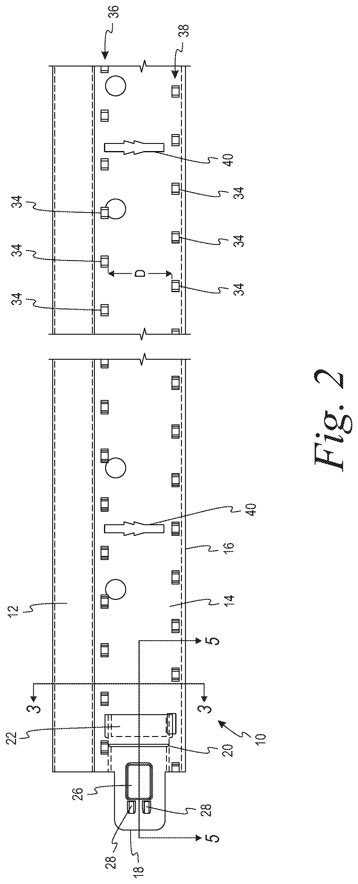
[0015] FIG. 2 is a side view of the main runner of FIG. 1.
[0016] FIG. 3 is a cross-sectional view of the main runner taken along line 3-3 of FIG. 2.
[0017] FIG. 4 is an end view of the main runner of FIG. 1.
[0018] FIG. 5 is an enlarged cross-sectional view of an end connector of the main runner taken along line 5-5 of FIG. 2.
[0019] FIG. 6 is an enlarged fragmentary portion of the end view of FIG. 3 showing details as to the hemmed flange.
[0020] FIG. 7 is an enlarged fragmentary portion of the end view of FIG. 3 showing details as to the reinforcing bulb.
DETAILED DESCRIPTION
[0021] With reference to FIGS. 1-7, a main runner or tee 10 for use in a suspended ceiling is disclosed comprising a reinforcing bead or bulb 12, a central web 14, and a pair of opposed flanges 16 for supporting ceiling panels or tiles, all as is well known in the art.
[0022] In keeping with a first aspect, the grid member includes integrally-formed first and second end connectors 18 extending from the first and second ends of the central web 14, respectively, past the flanges 16. With reference to FIG. 2, only a single end connector 18, extending from the left end of the main runner 10, is shown. As seen in FIG. 5, the first end connector 18 is displaced out of a plane defined by the central web 14 in a first direction "X", while the second end connector would be displaced out of the plane defined by the central web in a second direction opposite to the first direction "X". Each of the first and second end connectors have a distal edge 20.
[0023] A strap 22 adjacent each end of the central web 14 is deformed out of the plane of the central web in a direction "Y" opposite to the adjacent end connector, so that the strap 22 is configured to receive an end portion 24 of an end connector of a second tee.
[0024] Each of the first and second end connectors 18 further comprises a rectangularly-shaped embossment 26 extending out of a first side of the end connector, the embossment being defined by a proximal edge, a distal edge, an upper edge and a lower edge. First and second spaced-apart locking tabs 28, each having a proximal tapered camming surface 30 and distal locking surface 32, extend out of a second side of the end connector, such that the distal locking surface 32 of the locking tabs 28 engage the distal edge 20 of the end connector of the second tee.
[0025] In keeping with a second aspect, the two layers of the web 14 are preferably secured to each other by means of locking stitches or lances 34 that mechanically join together the two layers of the web 14, thus providing the main runner 10 with added resistance to torque. The stitches 34 may be of any configuration known in the art. In one embodiment, the stitches have a configuration such as that shown in U.S. Pat. No. 5,979055, which is incorporated herein by reference.
[0026] More specifically, the two layers of forming the web 14 of the main runner 10 are secured to each other by a first row 36 of longitudinally spaced stitches 34 at the upper end of the web 14 adjacent the bulb 12 and a second row 38 of longitudinally spaced stitches 34 at the lower end of the web 14 adjacent the flanges 16, with the stitches 34 in the first row 36 being staggered relative to the stitches 34 in the second row 38, Placing each row of stitches 34 as close to the adjacent bulb 12/flanges 16 is desired so as to maximize the spacing "D" between the two rows of stitches. The spacing between the two rows 36, 38, together with the stitches 34 in one row being staggered relative to the stitches 34 in the other row, provide greater rigidity and also avoids stitches in the area of the slots 40 that receive the connectors for cross tees associated with the main runner in the assembled suspension grid, thus avoiding potential interference between the stitches 34 and the connectors of the cross tees.
[0027] In another aspect, a lower cap 42 is applied to the flanges so that the free edges 16a of the flanges 16 are bent back on themselves along with the edges 42a of the cap 42 to provide a hemmed flange. This maximizes the surface contact between the cap 42 and the flanges 16, and increases the resistance between the two parts. This creates a composite action between the cap 42 and the flanges 1 that causes the two pieces to act as a single unit, such that the cap 42 does not slip or slide relative to the flanges 16. The cap 42 also provides for increased section properties for the main runner 10 due to the additional mass provided by the cap 42.
[0028] In another aspect, the bulb 12 of the runner 10 is modified to provide for a greater beam height than a standard runner configuration, More specifically, the vertical dimension of the bulb 12 is increased and the upper corners 44 of the bulb 12 are rounded. The rounded corners 44 help to avoid interference between the bulb 12 and light fixture housings that are supported in the assembled grid system. In an exemplary embodiment, the bulb 12 has a height of 0.515'' and a width of 0.250'', with the corners of the bulb having a radius of 0.093'', while the runner has an overall height of 1.640''.
[0029] As noted above, the enhanced strength provided to a main runner having the combination of features described above permit the runner to be formed of thinner material than the prior art runner without compromising the beam strength of the runner. By way of example, the thickness of the sheet material from which the main runner is roll formed may be reduced on the order of 20% (e.g., from 0.015'' to 0.012'')
[0030] Thus, an improved main runner or beam for a suspended ceiling grid has been provided. While the main runner has been described in terms of certain preferred embodiments, there is no intent to limit the invention to the same. Instead, the invention is defined by the scope of the following claims.
* * * * *
D00000
D00001
D00002
D00003
D00004
D00005
XML
uspto.report is an independent third-party trademark research tool that is not affiliated, endorsed, or sponsored by the United States Patent and Trademark Office (USPTO) or any other governmental organization. The information provided by uspto.report is based on publicly available data at the time of writing and is intended for informational purposes only.
While we strive to provide accurate and up-to-date information, we do not guarantee the accuracy, completeness, reliability, or suitability of the information displayed on this site. The use of this site is at your own risk. Any reliance you place on such information is therefore strictly at your own risk.
All official trademark data, including owner information, should be verified by visiting the official USPTO website at www.uspto.gov. This site is not intended to replace professional legal advice and should not be used as a substitute for consulting with a legal professional who is knowledgeable about trademark law.