Peptide Nucleic Acid Functionalized Hydrogel Microneedles For Sampling And Detection Of Interstitial Fluid Nucleic Acids
Irvine; Darrell J. ; et al.
U.S. patent application number 16/887649 was filed with the patent office on 2020-12-03 for peptide nucleic acid functionalized hydrogel microneedles for sampling and detection of interstitial fluid nucleic acids. The applicant listed for this patent is Massachusetts Institute of Technology. Invention is credited to Dana Al Sulaiman, Jason Y.H. Chang, Darrell J. Irvine, Sylvain Ladame.
| Application Number | 20200377929 16/887649 |
| Document ID | / |
| Family ID | 1000005060052 |
| Filed Date | 2020-12-03 |


View All Diagrams
| United States Patent Application | 20200377929 |
| Kind Code | A1 |
| Irvine; Darrell J. ; et al. | December 3, 2020 |
PEPTIDE NUCLEIC ACID FUNCTIONALIZED HYDROGEL MICRONEEDLES FOR SAMPLING AND DETECTION OF INTERSTITIAL FLUID NUCLEIC ACIDS
Abstract
The present disclosure relates to a device, comprising a base and a plurality of microneedles attached to the base, wherein each microneedle has an outer surface; the outer surface of at least one microneedle being coated with a composition comprising at least one polymer and least one Peptide Nucleic Acid (PNA). The present disclosure additionally relates to a method of detecting an analyte in interstitial fluid (ISF), comprising contacting the device to a subject, for example, to human skin.
| Inventors: | Irvine; Darrell J.; (Arlington, MA) ; Chang; Jason Y.H.; (Cambridge, MA) ; Ladame; Sylvain; (Tring, GB) ; Al Sulaiman; Dana; (London, GB) | ||||||||||
| Applicant: |
|
||||||||||
|---|---|---|---|---|---|---|---|---|---|---|---|
| Family ID: | 1000005060052 | ||||||||||
| Appl. No.: | 16/887649 | ||||||||||
| Filed: | May 29, 2020 |
Related U.S. Patent Documents
| Application Number | Filing Date | Patent Number | ||
|---|---|---|---|---|
| 62854475 | May 30, 2019 | |||
| Current U.S. Class: | 1/1 |
| Current CPC Class: | G01N 21/6428 20130101; C12Q 2565/629 20130101; C12Q 1/6823 20130101; C12Q 2565/1025 20130101; C12Q 1/6806 20130101; C12M 41/36 20130101 |
| International Class: | C12Q 1/6806 20060101 C12Q001/6806; C12Q 1/6823 20060101 C12Q001/6823; G01N 21/64 20060101 G01N021/64; C12M 1/34 20060101 C12M001/34 |
Goverment Interests
GOVERNMENT SUPPORT
[0002] This invention was made with government support under Grant No. W911NF-13-D-0001 awarded by the Army Research Office (ARO). The government has certain rights in the invention.
Claims
1. A device for detecting an analyte, comprising a base, and a plurality of microneedles attached to the base, wherein: each microneedle has an outer surface; and the outer surface of at least one microneedle is coated with a composition comprising at least one polymer and least one first Peptide Nucleic Acid (PNA).
2. The device of claim 1, wherein the composition further comprises at least one second PNA, wherein the second PNA is different from the first PNA.
3. The device of claim 1, wherein the polymer is hydrophilic.
4. The device of claim 1, wherein the polymer is alginate, xanthan, dextran, hyaluronic acid, poly(vinylalcohol) (PVA), polymethacrylic acid (PMAA), polyacrylic acid (PAA), poly(N-vinylpyrrolidone) (PVP), poly(lactic-co-glycolic acid) (PLGA), poly(N-isopropylacrylamide), poly(ethylene glycol) (PEG), poly(propylene oxide) (PPO), poly(ethylene glycol) diacrylate/dimethacrylate (PEGDA/PEGDMA), or poly(ethylene glycol) acrylate/methacrylate (PEGA/PEGMA), or a combination thereof.
5. The device of claim 1, wherein the polymer is alginate.
6. The device of claim 1, wherein the polymer is covalently attached to the first PNA, optionally by a linker.
7. The device of claim 2, wherein the polymer is covalently attached to the second PNA, optionally by a linker.
8. The device of claim 6, wherein the linker is selected from --OC(.dbd.O)--, --(O.dbd.)CO--, --NH--C(.dbd.O)--, --C(.dbd.O)NH--, --O--, --NH--C(.dbd.O)--NH--, or --S--, wherein Z indicates a point of attachment of the linker to the polymer, to the first PNA, or to the second PNA.
9. The device of claim 6, wherein the linker is represented by structural formula (I) or (Ia), ##STR00017## wherein indicates a point of attachment of the linker to the polymer, to the first PNA, or to the second PNA.
10. The device of claim 6, wherein the linker cleavable.
11. The device of claim 10, wherein the linker is a photocleavable linker represented by structural formula (II) or (IIa), ##STR00018## wherein indicates a point of attachment of the linker to the polymer, to the first PNA, or to the second PNA.
12. The device of claim 1, wherein the first PNA comprises from 5 to 30 nucleobases.
13. The device of claim 1, wherein the first PNA comprises from 5 to 8 nucleobases.
14. The device of claim 1, wherein the second PNA comprises from 5 to 8 nucleobases.
15. The device of claim 2, wherein: the analyte is a nucleic acid; the first PNA is complementary to the 5' end of the nucleic acid; and the second PNA is complementary to the 3' end of the nucleic acid.
16. The device of claim 1, wherein the analyte is microRNA.
17. The device of claim 6, wherein the first PNA is represented by a structural formula selected from ##STR00019## wherein indicates a point of attachment of the first PNA to the linker.
18. The device of claim 6, wherein: the first PNA comprises a first probe head; the second PNA comprises a second probe head; and the first probe head and the second probe head selectively bind each other, thereby producing a detectable signal.
19. The device of claim 18, wherein the first probe head comprises a chemical moiety selected from the group consisting of ##STR00020## and the second probe head comprises a chemical moiety selected from the group consisting of ##STR00021## ##STR00022## wherein: is a point of attachment of the chemical moiety to the first PNA or to the second PNA; each R or R' is independently selected from Halogen, --NO.sub.2, --OH, --NH.sub.2, --NH(C.sub.1-6 alkyl), --N(C.sub.1-6 alkyl).sub.2, --NCS, C.sub.1-6 alkyl, C.sub.1-6 haloalkyl, C.sub.6-10 aryl, 5- to 12-membered heteroaryl, --O(C.sub.1-6 alkyl), --C(O)O(C.sub.1-6 alkyl), --OC(O)(C.sub.1-6 alkyl), --C(O)NH.sub.2, --C(O)NH(C.sub.1-6 alkyl), --C(O)N(C.sub.1-6 alkyl).sub.2, --NHC(O)(C.sub.1-6 alkyl), --N(C.sub.1-6 alkyl)C(O)(C.sub.1-6 alkyl), --SO.sub.2(C.sub.1-6 alkyl), --SO.sub.2(C.sub.6-10 aryl), and --SO.sub.3.sup.-X.sup.+; X.sup.+ is Li.sup.+, Na.sup.+, K.sup.+, or N(C.sub.1-6 alkyl).sub.4.sup.+; m is 0 to 2; and n is 0 to 4.
20. The device of claim 18, wherein: the first probe head comprises a thiol and the second probe head comprises a chemical moiety represented by the structural formula (IV) or structural formula (V): ##STR00023## or the first probe head comprises a chemical moiety represented by the following structural formula ##STR00024## and the second probe head comprises a chemical moiety represented by the following structural formula ##STR00025## wherein indicates a point of attachment of the chemical moiety to the first PNA or to the second PNA.
21. The device of claim 18, wherein the first PNA is represented by a structural formula selected from ##STR00026##
22. The device of claim 18, wherein the second PNA is represented by a structural formula selected from ##STR00027## wherein indicates a point of attachment of the first PNA to the linker.
23. The device of claim 1, wherein the first PNA is a hairpin PNA comprising a third probe head; and further wherein the third probe head produces a detectable signal upon the hairpin PNA binding to the analyte.
24. The device of claim 23, wherein the third probe head comprises a chemical moiety selected from the group consisting of ##STR00028## wherein: is a point of attachment of the chemical moiety to the first PNA or to the second PNA; each R or R' is independently selected from Halogen, --NO.sub.2, --OH, --NH.sub.2, --NH(C.sub.1-6 alkyl), --N(C.sub.1-6 alkyl).sub.2, --NCS, C.sub.1-6 alkyl, C.sub.1-6 haloalkyl, C.sub.6-10 aryl, 5- to 12-membered heteroaryl, --O(C.sub.1-6 alkyl), --C(O)O(C.sub.1-6 alkyl), --OC(O)(C.sub.1-6 alkyl), --C(O)NH.sub.2, --C(O)NH(C.sub.1-6 alkyl), --C(O)N(C.sub.1-6 alkyl).sub.2, --NHC(O)(C.sub.1-6 alkyl), --N(C.sub.1-6 alkyl)C(O)(C.sub.1-6 alkyl), --SO.sub.2(C.sub.1-6 alkyl), --SO.sub.2(C.sub.6-10 aryl), and --SO.sub.3.sup.-X.sup.+; X.sup.+ is Li.sup.+, Na.sup.+, K.sup.+, or N(C.sub.1-6 alkyl).sub.4.sup.+; and n is 0 to 4.
25. The device of claim 18, wherein the detectable signal is fluorescent signal.
26. The device of claim 18, wherein the detectable signal is electrochemical signal.
27. A method of detecting an analyte in interstitial fluid (ISF) of a subject, comprising: contacting the subject with the device of claim 18; exposing the device to the ISF of the subject; detaching the device from the subject; and measuring an intensity of the detectable signal.
28. A method of detecting an analyte in ISF of a subject, comprising: contacting the subject with the device of claim 1, and exposing the device to the ISF of the subject.
29. The method of claim 28, further comprising detaching the device from the subject.
30. The method of claim 28, further comprising contacting the device with a first detection reagent, wherein the first detection reagent binds to the analyte and to produce a first signal.
31. The method of claim 30, wherein the first signal is a fluorescence, absorbance, or electrical signal.
32. The method of claim 28, further comprising determining a concentration of the analyte in ISF of the subject.
33. The method of claim 32, further comprising measuring an intensity of the first signal, thereby determining the concentration of the analyte.
34. The method of claim 28, wherein the first detection reagent is selected from a fluorogenic reagent or a DNA intercalator.
35. The method of claim 28, wherein the first detection reagent is selected from SYBR-Safe, SYBR-green, SYBR-red, YOYO-1, YOYO-3, TOTO-1, TOTO-3, TOPO-1, TOPO-3, POPO-1, POPO-3, Thiazole orange, or Ethidium bromide.
36. The method of claim 28, wherein the analyte forms an analyte:PNA complex with the first PNA.
37. The method of claim 28, wherein the analyte further forms an analyte:PNA complex with the second PNA.
38. The method of claim 37, wherein the linker is photocleavable, further comprising exposing the device to electromagnetic radiation, thereby releasing a free PNA: analyte complex.
39. The method of claim 38, further comprising contacting the free PNA:analyte complex with a second detection agent, wherein the second detection agent binds to the free PNA:analyte complex and produce a second signal.
40. The method of claim 39, wherein the second signal is a fluorescence, absorbance, or electrical signal.
41. The method of claim 39, further comprising determining the concentration of the free PNA:analyte complex.
42. The method claim 41, further comprising measuring an intensity of the second signal, thereby determining the concentration of the free PNA:analyte complex.
43. The method of claim 39, wherein the second detection reagent is selected from a fluorogenic reagent or a DNA intercalator.
44. The method of claim 39, wherein the second detection reagent is selected from SYBR-Safe, SYBR-green, SYBR-red, YOYO-1, YOYO-3, TOTO-1, TOTO-3, TOPO-1, TOPO-3, POPO-1, POPO-3, Thiazole orange, Ethidium bromide, molecular beacon, Taqman probe, or Lexicon probe.
45. A method of detecting an analyte in ISF of a subject, comprising: contacting the subject with the device of claim 1; exposing the device to the ISF of the subject; detaching the device from the subject; eluting the analyte from the device; and exposing the analyte to a detection agent, wherein the detection agent binds to the analyte.
46. The method of claim 45, wherein the detection reagent is selected from a fluorogenic reagent, a DNA intercalator, or a third PNA.
47. The method of claim 45, wherein the detection reagent is a third PNA.
48. The method of claim 28, further comprising determining a concentration of the analyte.
49. The method of claim 28, wherein contacting the subject comprises contacting a skin surface of the subject.
50. The method of claim 28, wherein the subject is a human subject.
51. The method of claim 28, wherein the analyte is a nucleic acid.
52. The method of claim 28, wherein the analyte is RNA.
53. The method of claim 28, wherein the analyte is microRNA.
54. The method of claim 28, wherein the analyte is DNA.
55. The method of claim 51, wherein the first PNA is complementary to the 5' end of the nucleic acid, and the second PNA is complementary to the 3' end of the nucleic acid.
56. The method of claim 28, wherein the analyte comprises a biomarker for a disease selected from cancer or infection.
57. The method of claim 56, wherein the infection is bacterial infection, viral infection, viroid infection, parasite infection, protozoa infection, or fungal infection.
58. The method of claim 45, further comprising determining a concentration of the analyte.
59. The method of claim 45, wherein contacting the subject comprises contacting a skin surface of the subject.
60. The method of claim 45, wherein the subject is a human subject.
61. The method of claim 45, wherein the analyte is a nucleic acid.
62. The method of claim 45, wherein the analyte is RNA.
63. The method of claim 45, wherein the analyte is microRNA.
64. The method of claim 45, wherein the analyte is DNA.
65. The method of claim 61, wherein the first PNA is complementary to the 5' end of the nucleic acid, and the second PNA is complementary to the 3' end of the nucleic acid.
66. The method claim 45, wherein the analyte comprises a biomarker for a disease selected from cancer or infection.
67. The method of claim 66, wherein the infection is bacterial infection, viral infection, viroid infection, parasite infection, protozoa infection, or fungal infection.
Description
RELATED APPLICATION(S)
[0001] This application claims the benefit of U.S. Provisional Application No. 62/854,475, filed on May 30, 2019. The entire teachings of the above application are incorporated herein by reference.
BACKGROUND OF THE INVENTION
[0003] Minimally-invasive technologies that can sample and detect cell-free nucleic acid biomarkers from liquid biopsies have recently emerged as clinically useful for early diagnosis and longitudinal monitoring of a broad range of pathologies, including cancer. Although blood has been so far the most commonly interrogated body fluid, skin interstitial fluid has been mostly overlooked despite containing the same broad variety of molecular biomarkers originating from cells and surrounding blood capillaries. Minimally-invasive technologies have emerged as a method to sample this fluid in a pain-free manner and often take the form of microneedle patches.
[0004] Liquid biopsies have the potential to revolutionize the way patients are screened, treated and monitored, all of which are key drivers of precision medicine (G. Siravegna, S. Marsoni, S. Siena, A. Bardelli, Nat. Rev. Clin. Oncol. 2017, 14, 531-548; E. Crowley, F. Di Nicolantonio, F. Loupakis, A. Bardelli, Nat. Rev. Clin. Oncol. 2013, 10, 472-484; S. Ono, S. Lam, M. Nagahara, D. S. B. Hoon, J. Clin. Med. 2015, 4, 1890-1907; G. Brock, E. Castellanos-Rizaldos, L. Hu, C. Coticchia, J. Skog, Transl. Cancer Res. 2015, 4, 280-290.) Although affordable full genome sequencing may help identify individuals at risk of developing specific pathologies, snapshots provided by point-of-care testing through simple technologies that are both low-cost and highly automated remain essential for public screening or personalized longitudinal monitoring. Circulating, cell-free nucleic acids (cfNAs) in liquid biopsies have been reported as predictive, diagnostic and prognostic biomarkers for a broad range of conditions, most notably cancer (T. H. Rainer, N. Y. L. Lam, Ann. N. Y. Acad. Sci. 2006, 1075, 271-277; M. Fleischhacker, B. Schmidt, Biochim. Biophys. Acta 2007, 1775, 181-232; V. Swamp, M. R. Rajeswari, FEBS Lett. 2007, 581, 795-799; E. Danese, M. Montagnana, C. Fava, G. C. Guidi, Semin. Thromb. Hemost. 2014, 40, 766-773). Among them microRNAs (or miRs) (D. P. Bartel, Cell 2004, 116, 281-297; V. Ambros, Nature 2004, 431, 350-355; P. S. Meltzer, Nature 2005, 435, 745-746; Y. Saito, P. A. Jones, Cell Cycle 2006, 5, 2220-2222; C. M. Croce, Nat. Rev. Genet. 2009, 10, 704-714; W. C. S. Cho, Int. J. Biochem. Cell Biol. 2010, 42, 1273-1281), a class of non-coding RNAs 19-25 nucleotides in length, hold the greatest promise as either individual biomarkers or in combinations (J. Lu, G. Getz, E. A. Miska, E. Alvarez-Saavedra, J. Lamb, D. Peck, A. Sweet-Cordero, B. L. Ebert, R. H. Mak, A. A. Ferrando, J. R. Downing, T. Jacks, H. R. Horvitz, T. R. Golub, Nature 2005, 435, 834-838; S. Volinia, M. Galasso, M. E. Sana, T. F. Wise, J. Palatini, K. Huebner, C. M. Croce, Proc. Nat. Acad. Sci. USA 2012, 109, 3024-3029; A. Sita-Lumsden, D. A. Dart, J. Waxman, C. Bevan, Br. J. Cancer 2013, 108, 1925-1930; P. Ulivi, W. Zoli, Molecules 2014, 19, 8220; A. R. Halvorsen, o. Helland, P. Gromov, V. T. Wielenga, M. L. M. Talman, N. Brunner, V. Sandhu, A. L. Borresen-Dale, I. Gromova, V. D. Haakensen, Mol. Oncol. 2017, 11, 220-234). Hence, there is a growing demand for sensing technologies that can detect specific nucleic acids in biological fluids and that can be implemented in the clinic.
[0005] Peptide nucleic acids (PNAs) recently emerged as promising probes for nucleic acid detection. PNAs are class of oligonucleotide mimics wherein the entire deoxyribose phosphate backbone has been replaced by a chemically different, structurally homomorphous backbone composed of (2-aminoethyl)glycine units. The synthetic backbone provides PNA with unique hybridization characteristics. Unlike DNA and RNA, the PNA backbone is not charged. Consequently, there is no electrostatic repulsion when PNAs hybridize to its target nucleic acid sequence, giving a higher stability to the PNA-DNA or PNA-RNA duplexes than the natural homo- or heteroduplexes. In addition, selective hybridization of PNA to DNA is less tolerant of base pair mismatches than DNA-DNA hybridization.
[0006] A further advantage of PNAs is that they are less susceptible to enzymatic degradation and are more stable than nucleic acid in various chemical environments.
[0007] PNAs can be synthesized to target particular nucleic acid sequences, thus providing an opportunity for highly selective nucleic acid analysis. Peptide Nucleic Acids (PNAs) are known per se and can be prepared in accordance with any of the various procedures referred to in B. Hyrup, P. E. Nielsen, Bioorganic & Medicinal Chemistry, 1996, 4, 5-23. Examples of PNA syntheses are disclosed, for example, in U.S. Pat. Nos. 5,539,083 and 6,433,134, each of which is incorporated herein by reference in its entirety.
[0008] In summary, PNAs can be used as stable, efficient, and selective probes for detection and isolation of nucleic acids, including cfNAs.
[0009] Research on cfNAs has so far been limited almost exclusively to those found in blood or urine (J. A. Weber, D. H. Baxter, S. Zhang, D. Y. Huang, K. H. Huang, M. J. Lee, D. J. Galas, K. Wang, Clin. Chem. 2010, 56, 1733-1741; X. Chen, Y. Ba, L. Ma, X. Cai, Y. Yin, K. Wang, J. Guo, Y. Zhang, J. Chen, X. Guo, Q. Li, X. Li, W. Wang, Y. Zhang, J. Wang, X. Jiang, Y. Xiang, C. Xu, P. Zheng, J. Zhang, R. Li, H. Zhang, X. Shang, T. Gong, G. Ning, J. Wang, K. Zen, J. Zhang, C.-Y. Zhang, Cell Res. 2008, 18, 997-1006; A. K. Chan, R. W. Chiu, Y. D. Lo, Ann. Clin. Biochem. 2003, 40, 122-130; O. E. Bryzgunova, T. E. Skvortsova, E. V. Kolesnikova, A. V. Starikov, E. Y. Rykova, V. V. Vlassov, P. P. Laktionov, Ann. N. Y. Acad. Sci. 2006, 1075, 334-340). However, recent experimental evidence suggests that all species of RNA (including miRs) previously found in blood are also present, in similar proportions, within interstitial fluid (ISF) (P. R. Miller, R. M. Taylor, B. Q. Tran, G. Boyd, T. Glaros, V. H. Chavez, R. Krishnakumar, A. Sinha, K. Poorey, K. P. Williams, S. S. Branda, J. T. Baca, R. Polsky, Commun. Biol. 2018, 1, 173), validating this type of bodily fluid as a greatly overlooked source of biomarkers for personalized medicine. Surrounding cells within a tissue, ISF serves as an exchange medium between blood plasma and cells and contains a combination of molecular constituents found in both sources. Skin ISF is found within several hundred microns of the skin surface, primarily in the connective tissue dermis where only few capillary beds and pain receptors reside. It can therefore be sampled in a pain-free manner, without any risk of blood contamination. This contrasts with blood drawing techniques that can be invasive (venous blood) or result in poor quality samples (fingerstick capillary blood).
[0010] Additionally, sampling ISF can allow one to determine localized concentrations of biomarkers, thus providing information that is particularly valuable in the cases of certain infections or malignancies. In those cases, the necessary information about the local biomarker concentrations cannot be determined through blood or urine analysis.
[0011] Minimally-invasive technologies for skin ISF sampling have emerged that are based on compact patches of microneedles (MNs) (C. Kolluru, M. Williams, J. Chae, M. R. Prausnitz, Adv. Healthc. Mater. 2019 8, e1801262; P. P. Samant, M. R. Prausnitz Proc. Natl Acad. Sci. U.S.A. 2018, 115, 4583-4588; P. R. Miller, R. J. Narayan, R. Polsky, J. Mater. Chem. B 2016, 4, 1379-1383; L. Ventrelli, L. Marsilio Strambini, G. Barillaro, Adv. Healthc. Mat. 2015, 4, 2606-2640; B. Chua, S. P. Desai, M. J. Tierney, J. A. Tamada, A. N. Jina, Sens. Actuators A Phys. 2013, 203, 373-381; Y. Ito, Y. Inagaki, S. Kobuchi, K. Takada, T. Sakaeda, Inter. J. Med. Sci. 2016, 13, 271; E. V. Mukerjee, S. D. Collins, R. R. Isseroff, R. L. Smith, Sens. Actuators A Phys. 2004, 114, 267-275; P. M. Wang, M. Cornwell, M. R. Prausnitz, Diabetes Technol. Ther. 2005, 7, 131-141). They are typically made of an array of microscale solid, porous or hollow needles from materials such as glass, metal, silicon or other polymers (A. V. Romanyuk, V. N. Zvezdin, P. Samant, M. I. Grenader, M. Zemlyanova, M. R. Prausnitz, Anal. Chem. 2014, 86, 10520-10523; L. Liu, H. Kai, K. Nagamine, Y. Ogawa, M. Nishizawa, RSC Adv. 2016, 6, 48630-48635). Hollow needles were designed to create pathways for ISF extraction via capillary force or vacuum-induced suction. They represent useful alternatives to invasive sampling technologies traditionally based on micro-dialysis and requiring tubing implantation under local anesthetics. Current limitations of many of the MN patches engineered so far include low sampling capacity (<2 .mu.L) and/or long sampling times (e.g. >1 h to sample enough ISF volumes for subsequent biomarker analysis). In addition, there has been no report of MNs engineered to sample and detect specific nucleic acid biomarkers from skin ISF. So far, MN were at best used for sampling and releasing total skin ISF and circulating nucleic acids detected after heavy sample processing and PCR-based analysis (R. L. Smith, S. D. Collins, J. Duy, T. D. Minogue, Proc. SPIE 2018, 10491, doi: 10.1117/12.2299264).
SUMMARY OF THE INVENTION
[0012] The present disclosure relates to a device for detecting an analyte, comprising a base, and a plurality of microneedles attached to the base, wherein: each microneedle has an outer surface; and the outer surface of at least one microneedle is coated with a composition comprising at least one polymer and least one first Peptide Nucleic Acid (PNA).
[0013] The present disclosure relates to a method of detecting an analyte in interstitial fluid (ISF) of a subject, comprising: contacting the subject with the device of the disclosure, exposing the device to the ISF of the subject; detaching the device from the subject; and measuring an intensity of the detectable signal.
[0014] The present disclosure relates to a method of detecting an analyte in interstitial fluid (ISF) of a subject, comprising: contacting the subject with the device of the disclosure, and exposing the device to the ISF of the subject.
[0015] The present disclosure additionally relates to a method of detecting an analyte in interstitial fluid (ISF) of a subject, comprising: contacting the subject with the device; exposing the device to the ISF of the subject; detaching the device from the subject; eluting the analyte from the device; and exposing the analyte to a detection agent, wherein the detection agent binds to the analyte.
BRIEF DESCRIPTION OF THE DRAWINGS
[0016] The patent or application file contains at least one drawing executed in color. Copies of this patent or patent application publication with color drawing(s) will be provided by the Office upon request and payment of the necessary fee.
[0017] FIG. 1. Schematic representation of the hydrogel-coated microneedle platform during sampling of the interstitial fluid. (a) Microneedle arrays (MN) are functionalized with bespoke peptide nucleic acid (PNA) probes (blue) which are covalently bound to an alginate hydrogel matrix via a photo-cleavable linker (PCL, yellow). Minimally-invasive sampling of skin interstitial fluid can be achieved by pressing the coated MN patch onto the skin for 15 min. (b) Scanning electron micrograph (5.0 kV, 100.times. magnification, 10 nm gold sputter coating) of the bare MNs and alginate-PNA hydrogel coated MNs (scale bar=100 .mu.m). (c) Schematic illustration of the generic protocol for MN sampling of target biomarker (red) and purification to remove non-target sequences (green). Circles represent a magnification of the alginate hydrogel coating on the MN patches. (i) When the MN is applied to sample a solution containing DNA, the target DNA sequence (red) hybridizes to the PNA probe (blue), forming a PNA:DNA complex. (ii) The MNs are washed to remove any non-specific molecules (green) which have diffused into the hydrogel matrix. (d) Swelling kinetics of the hydrogel MNs fitted by the Spring and Dashpot Voight-based model (black solid line), showing an equilibrium swelling capacity of 6.5.+-.0.2 .mu.L and a sampling rate constant of 0.74. Error bars show S.E.M. (N=6 MN patches).
[0018] FIG. 2. Validation of the MN sampling and release mechanism. (a) Calibration curve showing the mean fluorescence intensity of N=22 needles from two MN patches (error bars show S.E.M.), with a linear regression fitting and associated equation with fitting R.sup.2 and p-value. Fluorescence scanner images of representative MN patches after sampling fluorescently-labelled target DNA-210 at given concentrations (0-500 nM). Two color scale/calibration bars were used to facilitate visualization of the large dynamic range of fluorescence values (a (i) and a (ii), respectively). Inset shows magnification of the boxed area in (a) with the y-intercept (y-int) of the calibration curve and the limit of detection (LOD), calculated as three times the standard deviation of the y-int, equivalent to 6 nM. (b) Specificity of MN Platform. Comparison of the mean fluorescence of N=16 needles from 2 MN patches after sampling 500 nM of non-complementary DNA-141 (left, grey) and complementary DNA-210 (right, red), with fluorescence scans of representative MN patches shown below. (c) Schematic representation illustrating the two mechanisms for detecting captured unlabeled DNA, either (1) on-chip by dipping the MN into intercalator dye to visualize the PNA:DNA complex directly on the MN patch, or (2) by releasing the PNA:DNA complex into solution (UV irradiation) then adding an intercalator dye to the solution. On-chip detection results are plotted in (d) showing a significant difference in fluorescence between MN sampling DNA-210 (500 nM) or control (no DNA target in 100 mM phosphate buffer, pH 7.4) (unpaired two-tailed t-test, p<0.0001). UV-cleaved PNA:DNA complex detection in solution results are plotted in (e) showing an increase in fluorescence of the release solution after sampling target DNA-210 at 10, 100, or 200 nM. Note that data is normalized by subtracting the background fluorescence of the dye (2 control i.e. no DNA).
[0019] FIG. 3. MN Validation with human skin sample. (a) Experimental protocol for applying MNs to human skin biopsies. (Top) MNs were applied to 8 mm.sup.2 human skin biopsies for 15 min at 37.degree. C. to sample target and non-complementary DNA. (Bottom) Optical micrograph of human skin showing MNs penetration pattern stained with trypan blue (scale bar=300 .mu.m). SNR is represented as the ratio between average fluorescence intensity of MNs after sampling skin with DNA and without DNA (i.e. control) (N=48 from three MN patches). (b) Bars depict the SNRs after sampling skin incubated with only non-complementary DNA-141 (left, grey) or only complementary DNA-210 (right, blue), both tagged with Alexa-647 dye. (c) Bars depict the SNRs after sampling skin incubated with a mixture of complementary DNA-210 with a Cy5 dye and non-complementary DNA-210 with a Cy2 dye, imaged under Cy2 filter (left, grey) and Cy5 filter (right, red). In (b) and (c) Statistical analysis shows a significant difference between sampling target and non-complementary DNA (unpaired two-tailed t-test, p-value <0.0001). Representative MN fluorescence scans are displayed below. (d) Representative fluorescent confocal images from the captured DNA bound to the MN are shown in these images. (Left) Non-complementary DNA-141 imaged with 488.sub.ex/510.sub.em shows little to no fluorescence signal on the MNs. (Middle) Complementary DNA-210 imaged with 647.sub.ex/665.sub.em shows fluorescence signal bound to the MN. (Right) 3D projection of the fluorescence signal from a single microneedle. (Scale bar=200 .mu.m).
[0020] FIG. 4. Diagram showing the dimensions of the bare PLLA MN patches.
[0021] FIG. 5. (a) MALDI-TOF spectrum (matrix=sinapinic acid) and (b) chemical structure of the engineered PNA-alkyne directed against miR-210 (calculated MW 2191 g/mol).
[0022] FIG. 6. Scheme depicting the synthesis of alginate-azide.
[0023] FIG. 7. Scheme depicting the synthesis of Alginate-PNA from Alginate-azide via copper-catalyzed azide-alkyne cycloaddition reaction (Click Chemistry).
[0024] FIG. 8. .sup.1H NMR spectrum of an alginate-based hydrogel, identifying peaks A, B, and C.
[0025] FIG. 9. .sup.1H-NMR spectra of the engineered alginate hydrogels (D.sub.2O, 363 K, 400-500 MHz) showing (c) unmodified alginate; (b) alginate-azide; and the final alginate-PNA (a) with equivalent chemical structures shown on the right, highlighting the characteristic peaks and equivalent proton(s) on the structure.
[0026] FIG. 10. SEM micrographs (5.00 kV, 10 nm chromium coating, ZEISS Sigma 300) of calcium-crosslinked alginate coating (a) compared to a calcium crosslinked alginate-PNA coating (b) at 100K magnification (top) and 25K magnification (bottom).
[0027] FIG. 11. Atomic force microscopy images of Alginate-PNA coating (AFM, Asylum MFP-3D) conducted at room temperature in standard (AC) tapping mode with PPP-NCHR probes (NANOSENSORS.TM., Windsor Scientific), showing magnifications of the same sample.
[0028] FIG. 12. Validation of MN release mechanism. Fluorescence scans (a) and mean fluorescence (b) of individual MNs after sampling DNA (control, no UV irradiation) and after UV irradiation and release of DNA by 1, 2 or 4 J/cm.sup.2 of UV energy. Error bars show S.E.M (N=16 MNs). Inset shows the percentage of DNA released into solution after UV irradiation with different amounts of energy.
[0029] FIG. 13. Microneedle patch containing two PNAs complementary to the 5' and 3' ends of the same target miRNA for on-chip and off-chip detection.
[0030] FIG. 14. Microneedle patch containing two short PNA oligomers (5-8 bases long) that are functionalized with chemical probe heads for on-chip detection. Probes are designed to be complementary to two different part of the same miRNA, bringing both probe heads in close proximity to each other in order for both PNAs to hybridize simultaneously to the same miRNA.
[0031] FIG. 15. Structure of a hairpin PNA comprising a probe head.
DETAILED DESCRIPTION OF THE INVENTION
[0032] The present disclosure relates to a sampling and sensing device comprising microneedles that are coated with an alginate-peptide nucleic acid (PNA) hybrid material for sequence-specific sampling, isolation and detection of nucleic acid biomarkers from skin interstitial fluid. Characterized by fast sampling kinetics and large sampling capacity (.about.6.5 .mu.L in 2 min), this platform technology also enables for the first time the detection of specific nucleic acid biomarkers either on the patch itself or in solution after light-triggered release from the hydrogel. Considering the emergence of cell-free nucleic acids in bodily fluids as clinically informative biomarkers, platform technologies that can detect them in an automated and minimally invasive fashion have great potential for personalized diagnosis and longitudinal monitoring of patient-specific disease progression.
[0033] Hydrogel-coated MN patches can sample and isolate specific miRNA biomarkers from skin ISF at the fastest rate yet, while enabling the captured miRNA to be detected in situ (FIG. 1a). The versatile platform also offers the capability of light-triggered release of the miRNA for post-sampling off-chip analysis. Poly-L-Lactide (PLLA) arrays of 77 microneedles were used as a sampling platform, as their successful use for either transdermal vaccine delivery or ISF/cell sampling from the skin has been previously reported (A. Mandal, A. V. Boopathy, L. K. W. Lam, K. D. Moynihan, M. E. Welch, N. R. Bennett, M. E. Turvey, N. Thai, J. H. Van, J. C. Love, P. T. Hammond, D. J. Irvine, Sci. Transl. Med. 2018, 10, eaar2227; P. C. DeMuth, X. Su, R. E. Samuel, P. T. Hammond, D. J. Irvine, Adv. Mater. 2010, 22, 4851-4856; P. C. DeMuth, J. J. Moon, H. Suh, P. T. Hammond, D. J. Irvine, ACS Nano 2012, 6, 8041-8051; P. C. DeMuth, A. V. Li, P. Abbink, J. Liu, H. Li, K. A. Stanley, K. M. Smith, C. L. Lavine, M. S. Seaman, J. A. Kramer, Nat. Biotechnol. 2013, 31, 1082; P. C. DeMuth, W. F. Garcia-Beltran, M. L. Ai-Ling, P. T. Hammond, D. J. Irvine, Adv. Funct. Mater. 2013, 23, 161-172; P. C. DeMuth, Y. Min, B. Huang, J. A. Kramer, A. D. Miller, D. H. Barouch, P. T. Hammond, D. J. Irvine, Nat. Mater. 2013, 12, 367; P. C. DeMuth, Y. Min, D. J. Irvine, P. T. Hammond, Adv. Healthc. Mater. 2014, 3, 47-58). Other materials suitable for the microneedle arrays disclosed herein include polymers such as polycarbonate, as well polymers coated with a layer of metal, metal alloy, or metal-containing material, such as a metal oxide. For example, polymer-based microneedles can be coated with chromium, gold, iridium oxide, or a combination thereof.
[0034] 7.times.7 mm arrays were produced as previously reported, that were decorated with pyramidal-shaped MNs (FIG. 4). The height of the needles was set to 550 .mu.m to enable them to penetrate through the epidermis layer and reach the underlying, ISF containing, dermis layer. For sampling and isolation of specific miRNA biomarkers from skin ISF, the MN array was coated with alginate polymers functionalized with Peptide Nucleic Acid (PNA) capture probes for sequence-specific immobilization of the only miRNA of interest via Watson-Crick base pairing. When compared to standard oligonucleotides, PNAs offer the advantage of a greater affinity and sequence-specificity when hybridizing to complementary DNA or RNA strands (R. Bakhtiar, Biochem. Educ. 1998, 26, 277-280; S. Shakeel, S. Karim, A. Ali, J. Chem. Technol. Biotechnol. 2006, 81, 892-899; M. Egholm, O. Buchardt, L. Christensen, G. Behrens, S. M. Freier, D. A. Driver, R. H. Berg, S. K. Kim, B. Norden, P. E. Nielsen, Nature 1993, 365, 566-568; V. V. Demidov, V. N. Potaman, M. D. Frank-Kamenetskil, M. Egholm, O. Buchard, S. H. Sonnichsen, P. E. Nielsen, Biochem. Pharmacol. 1994, 48, 1310-1313; P. E. Nielsen, M. Egholm, Curr. Issues Mol. Biol. 1999, 1). Accessible through easily scalable solid-phase peptide synthesis, PNAs have proven highly valuable analytical tools for nucleic acid sensing, both in vitro and in vivo, and are particularly well suited for the detection of short oligonucleotides such as miRNAs. Herein, a 7-mer PNA was designed that was complementary to the 5'-end of miR-210, a recently identified biomarker for early systemic melanoma recurrence (FIG. 5). Melanoma patients with abnormally elevated levels of circulating miR-210 were indeed found to be more likely to have disease recurrence, reinforcing the need for a non-invasive test suitable for longitudinal monitoring (S. Ono, T. Oyama, S. Lam, K. Chong, L. J. Foshag, D. S. B. Hoon, Oncotarget 2015, 6, 7053-7064; S. K. Huang, D. S. B. Hoon, Mol. Oncol. 2016, 10, 450-463). DNA version of miR-210 (DNA-210) was chosen as the target of interest. The PNA was functionalized at its C-terminus with an alkyne moiety to facilitate its covalent immobilization to an azide-modified alginate via copper-catalyzed cycloaddition reaction (Click chemistry). A photo-cleavable linker (3-Amino-3-(2-nitrophenyl) propanoic acid) (PCL) was also introduced between the alkyne and the PNA sequence to enable the release of the PNA:DNA hybridization complex post ISF sampling via photo-activation with near-UV light (300-360 nm) (FIG. 1a). The alginate-azide polymer was prepared as previously reported by EDC/NHS mediated peptide coupling between low viscosity alginate and 11-azido-3,6,9-trioxyundecan-1-amine, leading to an average level of azide functionalization of 17 mol % (FIG. 6) (S. I. Presolski, V. P. Hong, M. G. Finn, Curr. Protoc. Chem. Biol. 2011, 3, 153-162). The alginate-PNA hybrid material was finally assembled by azide-alkyne cycloaddition reaction, in the presence of Cu(II) sulphate, Tris[(1-benzyl-1H-1,2,3-triazol-4-yl)methyl]amine (TBTA) and sodium ascorbate, leading to an overall level of PNA functionalization of 1 mol % as assessed by .sup.1H-NMR spectroscopy (FIGS. 7 and 8).
[0035] Coating of the MN arrays with the newly engineered alginate-PNA proceeded in three steps: pre-coating with poly-L-Lysine followed by deposition of the alginate and finally physical crosslinking with calcium chloride (CaCl.sub.2)), leaving enough time for the MN to dry between each step. Once fully dried, scanning electron microscopy (SEM) was used to characterize and compare the physical morphology at the surface of the MN patches with and without alginate-PNA hydrogel coating (FIG. 1b) To determine the effect of PNA functionalization on the alginate's physical properties, MN patches coated with unmodified alginate were also analyzed. The SEM micrographs of both types of alginate displayed an interconnected network of pores with a relatively consistent pore size. Although SEM only provides information on the hydrogels' structures in their non-swollen dehydrated form, it is noteworthy that the average pore size of the dehydrated alginate-PNA coating was approximately half that of the unmodified alginate (FIG. 10). This could be due to the hydrophobic nature of the charge-free PNAs limiting water uptake and reducing swelling, as previously observed when functionalizing hydrogel fibers with hydrophobic moieties (D. Al Sulaiman, P. Cadinu, A. P. Ivanov, J. B. Edel, S. Ladame, Nano Lett. 2018, 18, 6084-6093). Atomic Force Microscopy (AFM) was also used to gain an insight into the topography of the alginate-PNA on surface. For ease of imaging however, the hydrogel was deposited on a glass slide, but this time no lyophilization or metal coating was needed, therefore providing a more accurate representation of the hydrogel structure. The surface topography showed a relatively consistent and homogeneously distributed porous structure over the 50.times.50 .mu.m.sup.2 area with pores or voids of 200-800 nm (FIG. 11), only slightly larger than those observed, after lyophilization, by SEM. As earlier studies showed, small oligonucleotides the size of miRNAs could easily diffuse within such porous materials and hybridize to pre-embedded PNAs (D. Al Sulaiman, J. Y. H. Chang, S. Ladame, Angew. Chem. Int. Ed. 2017, 56, 5247-5251).
[0036] The main limitations of existing ISF sampling platforms are their low sampling capacity and low sampling rates. For example, micro-dialysis techniques typically sample at 1-5 .mu.L/min while less invasive capillary ultrafiltration is even slower, at 100-150 nL/min. The swelling behavior of the hydrogel-coated MNs was assessed in buffer (PBS) and at physiological body temperature (37.degree. C.). FIG. 1d describes the volume of liquid absorbed by the MN over time which can be fitted by the Spring and Dashpot Voight-based model commonly used for describing swelling kinetics of hydrogels. According to this model, the hydrogel-coated MNs have an equilibrium swelling capacity of 6.5.+-.0.2 .mu.L, with a sampling rate constant of 0.74, meaning that 63% of the full swelling capacity is achieved in less than 1 min. This compares very favorably with other recently reported hydrogel-coated MN sampling technologies and can at least in part be attributed to the large surface area of the MNs due their pyramidal shape and porous coating structure.
[0037] To test the ability of the MN patches to sample and isolate nucleic acids in a sequence specific manner, MNs were dipped into solutions (100 .mu.L) containing various amounts of DNA-210 (0-500 nM) labelled with Alexa 647 dye. After 15 min sampling, the MNs were washed thoroughly with water and dried overnight at room temperature before imaging with a fluorescence scanner (Typhoon FLA9500, GE Healthcare). As shown in FIG. 2a, a plot of the mean fluorescence intensity (N=22 individual microneedles from 2 different MN patches) versus DNA concentration demonstrates the ability of the patches to detect target concentrations as low as .about.6 nM, with a linear regime across almost 2 orders of magnitude (6-500 nM). Sequence specificity was then confirmed by demonstrating the statistically significant ability of the MN patch to discriminate between a complementary and a non-complementary DNA target, both labelled with the same fluorophore (FIG. 2b).
[0038] In order to demonstrate the possibility to release the captured nucleic acid from the microneedle, MN patches pre-incubated with fluorescently-labelled DNA-210 were placed tips-down in water (100 .mu.L) within a UV crosslinker (UVP) and irradiated with increasing amounts of UV energy (.lamda..sub.ex=315 nm, 0-4 J/cm.sup.2). After shaking for 1 h, the MNs were rinsed, dried and imaged on a fluorescence scanner. A significant loss in fluorescence intensity of the MN was observed post-irradiation that suggested the release of over 70% of the captured DNA after 1 min of irradiation (FIG. 12).
[0039] The MN patches were not only designed to sample specific endogenous nucleic acid biomarkers from skin ISF, but also to enable their quantitative detection once sampled. Two different mechanisms for sensing were explored that involved either (i) the direct visualization of the isolated biomarker whilst captured on the microneedle patch or (ii) an alternative two-step process involving light-triggered release of the PNA:DNA complex followed by detection in solution (FIG. 2c). For both sensing strategies, the MN patches were initially dipped into solutions (100 .mu.L) containing various amounts of unlabeled DNA-210 (10-200 nM), then washed thoroughly to remove any unbound DNA and dried. For direct visualization, the MN patches were then incubated in a solution of DNA intercalator (SYBR Safe, 2.times. concentration, Invitrogen), washed and imaged with a fluorescence scanner (FIG. 2d). For indirect visualization, the DNA-loaded MN were then placed tips-down into 100 .mu.L of water and irradiated for 3 min at 3 J/cm.sup.2 in a photo-crosslinker (BLX-315, .lamda..sub.ex=315 nm). A solution of DNA intercalator was then added to detect the PNA:DNA complex released in solution (FIG. 2e). Both strategies proved successful at detecting nM concentrations of nucleic acids sampled with the MN patches, highlighting the versatility of this platform. Whilst simpler and more direct on-chip detection is perfectly suited for applications that require testing at the point-of-care, the possibility of releasing the captured and purified (i.e. separated from all other ISF constituents, including other nucleic acid) material offer the possibility to detect and sequence less abundant biomarkers (through amplification-based methodologies).
[0040] Having validated the sensitivity and selectivity of the MN sampling in vitro, the sampling of specific nucleic acids from skin ISF directly in human skin, using an ex-vivo model, was investigated. Human abdominal skin samples were first prepared by incubation with either a complementary (DNA-210) or a non-complementary (DNA-141) oligonucleotide labelled with Alexa-647 dye (500 nM each) and then washed thoroughly with water. MN patches were then pressed onto the skin surface (15 min, 37.degree. C.) for sampling and then washed extensively and dried overnight before fluorescence imaging (FIG. 3a). Images were analyzed by taking the average fluorescence of individual microneedles on each patch (N=48 microneedles from three different MN patches). These results not only demonstrate that the MNs can indeed sample nucleic acids from skin ISF but also that they retain their high sequence specificity, capturing preferentially (15-fold) the DNA fragment complementary to the PNA incorporated into the hydrogel (FIG. 3b). To confirm these findings a second experiment was prepared where the skin samples were incubated in a solution containing a mixture of both DNA-210 (red bars) and DNA-141 (green bars) labelled with Alexa-647 and 6-FAM, respectively. After sampling (as described above), MN patches (N=3 per condition) were imaged successively under two excitation filters (FIG. 3c). Whilst no significant difference between the experiments with and without DNA was detectable with the Cy2 filter (for 6-FAM visualization), a very strong signal increase was observed between the DNA-free control and the experiment with DNA, confirming the efficient and sequence-specific capturing of DNA-210 spiked within human skin ISF. Fluorescent confocal imaging of the MNs was also performed to confirm the previous findings and visualize the DNA captured around each MN (FIG. 3d). Non-complementary DNA-141 imaged with 488ex/510em showed little to no fluorescence signal on the MNs (FIG. 3d, left), while complementary DNA-210 imaged with 647ex/665em showed fluorescence signal bound to the MN (FIG. 3d, middle). A 3D projection of the fluorescence signal from a single microneedle is also shown (FIG. 3d, right).
[0041] The disclosed technology can be modified to introduce 2 or more different PNA oligomers into the hydrogel. For example, FIG. 13 shows a schematic representation of an MN patch coated with engineered hydrogels functionalized with 2 short PNA oligomers (5-8 bases long) that are complementary to the 5' and 3' ends of the same target miRNA. In this case capturing of the miRNA of interest proceeded via sequence-specific hybridization to both short PNA probes whilst all miRNAs not fully complementary to both probes were washed away. Subsequent MRNA detection can be carried out on-chip or off-chip. On-chip detection was performed via addition of a fluorogenic DNA intercalator (e.g. SYBR-green, SYBR-safe, or Thiazole orange) to detect the amount of PNA:DNA heteroduplex present in the hydrogel. Off-chip detection was performed via addition of a (natural or functionalized) DNA oligonucleotide fully complementary to the miRNA of interest. The DNA:RNA heteroduplex can then be eluted of the hydrogel and detected in solution. Functionalization of the DNA oligonucleotide will include biotin and thiol or any other chemical functionality that will enable capturing of the released miRNA:DNA duplex onto particles or lateral flow assay.
[0042] Using 2 short PNA oligomers enables optimal sequence specificity for unique miRNA sequences. Only miRNA that are complementary to both PNA oligomers with remain bound to the MN through sequence specific hybridization whilst partially bound miRNAs (e.g. miRNAs complementary to only one of the PNA oligomers) will be eluted off through stringent washes prior to detection.
[0043] Alternatively, MN patches can be coated with engineered hydrogels functionalized with 2 or more short PNA oligomers (5-8 bases long) that are functionalized with chemical probe heads (FIG. 14). Probes are designed so that they are complementary to two different part of the same miRNA, bringing both probe heads in close proximity to each other with both PNA hybridize simultaneously to the same miRNA. Capturing of the miRNA of interest proceeds via sequence-specific hybridization to both short PNA probes whilst all miRNAs not fully complementary to both probes are washed away. miRNA detection is carried out on-chip using either an optical or electrochemical readout as a result of an on-chip oligonucleotide-templated reaction (OTR). Both probe heads are kept far away from each other unless they are both hybridized to the same template miRNA, therefore accounting for an extremely low background fluorescence. Example of probe head pairs can include, for example, a thiol derivative and a quenched coumarin; or an aniline derivative and a quinone.
[0044] Probe heads can be designed so that they can react with each other upon simultaneous binding to the same miRNA target to form an electrochemically active product with characteristic redox properties, significantly distinct from those of the unreacted probes (see example below), thus producing an electrochemical signal. The electrochemical signal generated upon formation of the product can be measured using electrochemistry techniques such as cyclic voltammetry (CV), differential pulse voltammetry (DPV), square wave voltammetry (SWV) electrochemical impedance spectroscopy (EIS) or amperometry.
[0045] A characteristic readout (optical or electrochemical) is provided by stimulus-responsive probe-heads already incorporated into the hydrogel structure through covalent attachment at the end of the PNA oligomers. This offers the advantage of a direct, real-time and on-chip monitoring of the miRNA biomarkers as they diffuse into the MN patch, without the need for further processing or use of additional chemicals. Most useful optical probe heads will (i) have a fluorescence quantum yield close to zero and react with each other to form a product with a high fluorescence quantum yield (i.e. fluorogenic probes) or (ii) will form a product that is characterized with excitation and/or emission wavelengths significantly different from those of the two probe heads (i.e. ratiometric probes). They will also ideally have emission and excitation wavelengths >450 nm to avoid interference from any background fluorescence. Most useful electrochemical probe heads will possess redox properties that are significantly different from those of the product (or adduct) formed upon reaction of the probe heads with each other.
[0046] Alternatively, MN patches can be coated with at least one folded PNA oligomer, such as hairpin PNA (as described, for example, in Armitage, B., Koch, T., Frydenlund, H., Orum, H., Schuster, G. B., Biochemistry 1998, 37(26), 9417-9425), that is functionalized with a chemical probe head. Hairpin PNAs are single-stranded PNA oligomers having self-complementary sequences that form stem-loop-containing structures. An Example of a hairpin PNA comprising a probe head is shown in FIG. 15.
[0047] The PNA is designed to be complementary to the target miRNA. Capturing of the miRNA of interest proceeds via unfolding and sequence-specific hybridization to the PNA probe resulting in a characteristic change in the optical or electrochemical properties of the probe head The change in the probe head environment is caused by the conformational change of the PNA, and results in generation of a detectable signal.
[0048] In summary, a new generation of MN patches coated with hybrid alginate-PNA hydrogels that can sample up to 6.5 .mu.L of fluid in 2 minutes was developed. Unlike other sampling technologies reported to date, it was demonstrated that attaching PNA oligomers to the hydrogel's fibers also enables the specific sampling, purification and release of the only nucleic acid fragments that are complementary to the PNA sequence. This versatile platform can therefore by easily tuned by simply adapting the PNA sequence to that of any miRNA of interest. Functionalization of the hydrogel with different PNA sequences complementary to different miRNAs will also enable the sampling and sensing of multiple miRNAs simultaneously (known as multiplexed analysis or profiling). Optical sensing of the captured biomarkers is also possible, either directly on-chip or in-solution after an additional light-triggered release step. Using a human skin ex-vivo model, it was demonstrated that this technology could efficiently capture nucleic acids spiked within skin interstitial fluids with both high efficiency and sequence specificity. With the recent experimental evidence that skin ISF contains the same RNA species (including circulating miRNAs) as blood with comparable natural abundance, minimally-invasive technologies that can not only sample this body fluid but can also interrogate its composition have the potential to transform the field of molecular diagnostics from liquid biopsies.
Definitions
[0049] As used herein, "eluting" refers to the process of removing analytes from the adsorbent by running a suitable solvent or solution, called an "eluent", past the adsorbent/analyte complex.
[0050] As used herein, "probe head", also known as "terminating head group", refers to a chemical moiety covalently bound to the N-terminus or C-terminus of the PNA.
[0051] The term "selective binding", as used herein, refers to two molecules forming a complex having the dissociation constant (k.sub.d) of less than or equal to 10.sup.-6 M (e.g., 10.sup.-7, 10.sup.-8, 10.sup.-9, or 10.sup.-10 M).
[0052] The term "alkyl," as used herein, means a saturated straight-chain, branched or cyclic hydrocarbon. When straight-chained or branched, an alkyl group is typically C.sub.1-8, more typically C.sub.1-6; when cyclic, an alkyl group is typically C.sub.3-12, more typically C.sub.3-7. As such, "C.sub.1-6 alkyl" means a straight or branched saturated monovalent hydrocarbon radical having from one to six carbon atoms (e.g., 1, 2, 3, 4, 5 or 6). The terms "alkyl", "alkoxy", "hydroxyalkyl", "haloalkyl", "aralkyl", "alkoxyalkyl", "alkylamine", "dialkyamine", "alkylamino", "dialkyamino", "alkoxycarbonyl", "carbocyclylalkyl", "heterocyclylalkyl" and the like, used alone or as part of a larger moiety includes both straight and branched saturated chains containing one to eight carbon atoms. The term "cycloalkyl" used alone or as part of a larger moiety, shall include cyclic C.sub.3-12 hydrocarbons which are completely saturated. Examples of alkyl include, but are not limited to, methyl, ethyl, 1-propyl, 2-propyl, 1-butyl, 2-methyl-1-propyl, --CH.sub.2CH(CH.sub.3).sub.2), 2-butyl, 2-methyl-2-propyl, 1-pentyl, 2-pentyl 3-pentyl, 2-methyl-2-butyl, 3-methyl-2-butyl, 3-methyl-1-butyl, 2-methyl-1-butyl, 1-hexyl), 2-hexyl, 3-hexyl, 2-methyl-2-pentyl, 3-methyl-2-pentyl, 4-methyl-2-pentyl, 3-methyl-3-pentyl, 2-methyl-3-pentyl, 2,3-dimethyl-2-butyl, 3,3-dimethyl-2-butyl, 1-heptyl, 1-octyl, and the like.
[0053] The term "aryl," alone or in combination, as used herein, means an aromatic hydrocarbon radical of 6-18 carbon atoms (i.e., C.sub.6-18 aryl) derived by the removal of hydrogen atom from a carbon atom of a parent aromatic ring system. In some instances, an aryl group has 6-12 carbon atoms (i.e., C.sub.6-12 aryl), preferably 6-10 carbon atoms (i.e., C.sub.6-10 aryl). Some aryl groups are represented in the exemplary structures as "Ar." Aryl includes bicyclic radicals comprising an aromatic ring fused to a saturated, partially unsaturated ring, or aromatic carbocyclic or heterocyclic ring. In particular embodiments, aryl is one, two or three rings. Typical aryl groups include, but are not limited to, radicals derived from benzene (phenyl), substituted benzenes, naphthalene (naphthyl), anthracene (anthryl) etc. Other aryl groups include, indanyl, biphenyl, phenanthryl, acenaphthyl and the like. Preferably, aryl is phenyl group.
[0054] The term "halo" or "halogen" as used herein means halogen and includes, for example, and without being limited thereto, fluoro, chloro, bromo, iodo and the like, in both radioactive and non-radioactive forms. In a preferred embodiment, halo is selected from the group consisting of fluoro, chloro and bromo.
[0055] The term "haloalkyl", as used herein, includes an alkyl substituted with one or more F, Cl, Br, or I, wherein alkyl is defined above.
[0056] The term "heteroaryl", as used herein, refers to an aromatic radical of 5-18 ring atoms (i.e., a 5- to 18-membered heteroaryl), containing one or more heteroatoms independently selected from nitrogen, oxygen, and sulfur. A heteroaryl group can be monocyclic or polycyclic, e.g. a monocyclic heteroaryl ring fused to one or more carbocyclic aromatic groups or other monocyclic heteroaryl groups. The heteroaryl groups of this invention can also include ring systems substituted with one or more oxo moieties. In one aspect, heteroaryl has from 5-15 ring atoms (i.e., 5- to 15-membered heteroaryl), such as a 5- to 12-membered ring (i.e, a 5- to 12-membered heteroaryl). In certain instances, heteroaryl is a 5-membered heteroaryl and in other instances heteroaryl is a 6-membered heteroaryl. Examples of heteroaryl groups include, but are not limited to, pyridinyl, pyridazinyl, imidazolyl, pyrimidinyl, pyrazolyl, triazolyl, pyrazinyl, quinolyl, isoquinolyl, tetrazolyl, furyl, thienyl, isoxazolyl, thiazolyl, oxazolyl, isothiazolyl, pyrrolyl, quinolinyl, isoquinolinyl, indolyl, benzimidazolyl, benzofuranyl, cinnolinyl, indazolyl, indolizinyl, phthalazinyl, pyridazinyl, triazinyl, isoindolyl, purinyl, oxadiazolyl, thiazolyl, thiadiazolyl, furazanyl, benzofurazanyl, benzothiophenyl, benzotriazolyl, benzothiazolyl, benzoxazolyl, quinazolinyl, quinoxalinyl, naphthyridinyl, dihydroquinolyl, tetrahydroquinolyl, dihydroisoquinolyl, tetrahydroisoquinolyl, benzofuryl, furopyridinyl, pyrolopyrimidinyl, and azaindolyl. The foregoing heteroaryl groups may be C-attached or N-attached (where such is possible). For instance, a group derived from pyrrole may be pyrrol-1-yl (N-attached) or pyrrol-3-yl (C-attached).
[0057] The present disclosure relates to a device for detecting an analyte, comprising a base, and a plurality of microneedles attached to the base, wherein: each microneedle has an outer surface; and the outer surface of at least one microneedle is coated with a composition comprising at least one polymer and least one first Peptide Nucleic Acid (PNA).
[0058] In some embodiments, the composition further comprises at least one second PNA, wherein the second PNA is different from the first PNA.
[0059] In some embodiments, the polymer is hydrophilic. In some embodiments, the polymer is alginate, xanthan, dextran, hyaluronic acid, poly(vinylalcohol) (PVA), polymethacrylic acid (PMAA), polyacrylic acid (PAA), poly(N-vinylpyrrolidone) (PVP), poly(lactic-co-glycolic acid) (PLGA), poly(N-isopropylacrylamide), poly(ethylene glycol) (PEG), poly(propylene oxide) (PPO), poly(ethylene glycol) diacrylate/dimethacrylate (PEGDA/PEGDMA), or poly(ethylene glycol) acrylate/methacrylate (PEGA/PEGMA), or a combination thereof. In some embodiments, the polymer is alginate.
[0060] In some embodiments, the polymer is covalently attached to the first PNA, optionally by a linker. In some embodiments, the polymer is covalently attached to the second PNA, optionally by a linker. In some embodiments, the linker is selected from --OC(.dbd.O)--, --(O.dbd.)CO--, --NH--C(.dbd.O)-- , --C(.dbd.O)NH--, --O--, --NH--C(.dbd.O)--NH-, or --S--, wherein indicates a point of attachment of the linker to the polymer, to the first PNA, or to the second PNA. In some embodiments, the linker is represented by structural formula (I) or (Ia),
##STR00001##
wherein indicates a point of attachment of the linker to the polymer, to the first PNA, or to the second PNA
[0061] In some embodiments, the linker is cleavable. In some embodiments, the linker is photocleavable. In some embodiments, the linker is a photocleavable linker represented by structural formula (II) or (Ha),
##STR00002##
wherein indicates a point of attachment of the linker to the polymer, to the first PNA, or to the second PNA.
[0062] In some embodiments, the first PNA comprises from 5 to 30 nucleobases. In some embodiments, the first PNA comprises from 5 to 8 nucleobases. In some embodiments, the second PNA comprises from 5 to 8 nucleobases.
[0063] In some embodiments, the PNA comprises a modified peptide backbone. For example, the PNA is a .gamma.-PNA, an aegPNA, or an acpcPNA.
[0064] In some embodiments, the analyte is a nucleic acid; the first PNA is complementary to the 5' end of the nucleic acid; and the second PNA is complementary to the 3' end of the nucleic acid. In some embodiments, the is nucleic acid is microRNA.
[0065] In some embodiments, the first PNA is represented by the structural formula (III),
##STR00003##
In some embodiments, the first PNA is represented by a structural formula selected from
##STR00004##
wherein indicates a point of attachment of the first PNA to the linker. In some embodiments, the first PNA is represented by a structural formula selected from
##STR00005##
wherein indicates a point of attachment of the first PNA to the linker.
[0066] In some embodiments, the first PNA comprises a first probe head; the second PNA comprises a second probe head; and the first probe head and the second probe head selectively bind each other, thereby producing a detectable signal. In some embodiments, the first probe head comprises a chemical moiety selected from the group consisting of
##STR00006##
and the second probe head comprises a chemical moiety selected from the group consisting of
##STR00007## ##STR00008##
wherein: each R or R' is independently selected from Halogen, --NO.sub.2, --OH, --NH.sub.2, --NH(C.sub.1-6 alkyl), --N(C.sub.1-6 alkyl).sub.2, --NCS, C.sub.1-6 alkyl, C.sub.1-6 haloalkyl, C.sub.6-10 aryl, 5- to 12-membered heteroaryl, --O(C.sub.1-6 alkyl), --C(O)O(C.sub.1-6 alkyl), --OC(O)(C.sub.1-6 alkyl), --C(O)NH.sub.2, --C(O)NH(C.sub.1-6 alkyl), --C(O)N(C.sub.1-6 alkyl).sub.2, --NHC(O)(C.sub.1-6 alkyl), --N(C.sub.1-6 alkyl)C(O)(C.sub.1-6 alkyl), --SO.sub.2(C.sub.1-6 alkyl), --SO.sub.2(C.sub.6-10 aryl), and --SO.sub.3.sup.+X.sup.+; X.sup.+ is Li.sup.+, Na.sup.+, K.sup.+, or N(C.sub.1-6 alkyl).sub.4.sup.+; m is 0 to 2; and n is 0 to 4. In some embodiments, the first probe head comprises a thiol and the second probe head comprises a chemical moiety represented by the structural formula (IV) or structural formula (V):
##STR00009##
or the first probe head comprises a chemical moiety represented by the following structural formula
##STR00010##
and the second probe head comprises a chemical moiety represented by the following structural formula
##STR00011##
wherein indicates a point of attachment of the chemical moiety to the first PNA or to the second PNA.
[0067] In some embodiments, the first PNA is a hairpin PNA comprising a third probe head; and further wherein the third probe head produces a detectable signal upon the hairpin PNA binding to the analyte.
[0068] In some embodiments, the third probe head comprises a chemical moiety selected from the group consisting of
##STR00012##
wherein: is a point of attachment of the chemical moiety to the first PNA or to the second PNA;
[0069] each R or R' is independently selected from Halogen, --NO.sub.2, --OH, --NH.sub.2, --NH(C.sub.1-6 alkyl), --N(C.sub.1-6 alkyl).sub.2, --NCS, C.sub.1-6 alkyl, C.sub.1-6 haloalkyl, C.sub.6-10 aryl, 5- to 12-membered heteroaryl, --O(C.sub.1-6 alkyl), --C(O)O(C.sub.1-6 alkyl), --OC(O)(C.sub.1-6 alkyl), --C(O)NH.sub.2, --C(O)NH(C.sub.1-6 alkyl), --C(O)N(C.sub.1-6 alkyl).sub.2, --NHC(O)(C.sub.1-6 alkyl), --N(C.sub.1-6 alkyl)C(O)(C.sub.1-6 alkyl), --SO.sub.2(C.sub.1-6 alkyl), --SO.sub.2(C.sub.6-10 aryl), and --SO.sub.3.sup.+X.sup.+;
X.sup.+ is Li.sup.+, Na.sup.+, K.sup.+, or N(C.sub.1-6 alkyl).sub.4.sup.+; and n is 0 to 4.
[0070] In some embodiments, the detectable signal is fluorescent signal. In some embodiments, the detectable signal is electrochemical signal.
[0071] The present disclosure relates to a method of detecting an analyte in interstitial fluid (ISF) of a subject, comprising: contacting the subject with the device of the disclosure, exposing the device to the ISF of the subject; detaching the device from the subject; and measuring an intensity of the detectable signal.
[0072] The present disclosure relates to a method of detecting an analyte in ISF of a subject, comprising: contacting the subject with the device of the disclosure, and exposing the device to the ISF of the subject.
[0073] In some embodiments, the method further comprises detaching the device from the subject.
[0074] In some embodiments, the method further comprises contacting the device with a first detection reagent, wherein the first detection reagent binds the analyte and to produce a first signal. In some embodiments, the first signal is a fluorescence, absorbance, or electrical signal.
[0075] In some embodiments, the method further comprises determining a concentration of the analyte in ISF of the subject. In some embodiments, the method further comprises measuring an intensity of the first signal, thereby determining the concentration of the analyte.
[0076] In some embodiments, the first detection reagent is selected from a fluorogenic reagent or a DNA intercalator. In some embodiments, the first detection reagent is selected from SYBR-Safe, SYBR-green, SYBR-red, YOYO-1, YOYO-3, TOTO-1, TOTO-3, TOPO-1, TOPO-3, POPO-1, POPO-3, Thiazole orange, or Ethidium bromide.
[0077] In some embodiments, the analyte forms an analyte:PNA complex with the first PNA and with the second PNA, if present.
[0078] In some embodiments, the linker is photocleavable, and the method further comprises exposing the device to electromagnetic radiation, thereby releasing a free PNA:analyte complex. In some embodiments, the method further comprises contacting the free PNA:analyte complex with a second detection agent, wherein the second detection agent binds to the free PNA:analyte complex and produce a second signal. In some embodiments, the second signal is a fluorescence, absorbance, or electrical signal.
[0079] In some embodiments, the method further comprises determining the concentration of the free PNA:analyte complex. In some embodiments, the method further comprises measuring an intensity of the second signal, thereby determining the concentration of the free PNA:analyte complex.
[0080] In some embodiments, the second detection reagent is selected from a fluorogenic reagent or a DNA intercalator. In some embodiments, the second detection reagent is selected from SYBR-Safe, SYBR-green, SYBR-red, YOYO-1, YOYO-3, TOTO-1, TOTO-3, TOPO-1, TOPO-3, POPO-1, POPO-3, Thiazole orange, Ethidium bromide, molecular beacon, Taqman probe, or Lexicon probe.
[0081] In certain embodiments, the first detection agent and the second detection agent are the same. Alternatively, the first detection agent and the second detection agent are different.
[0082] In certain embodiments, only the first detection agent is used. In other embodiments, only the second detection agent is used.
[0083] In some embodiments, both the first detection agent and the second detection agent are used.
[0084] The present disclosure relates to a method of detecting an analyte in interstitial fluid (ISF) of a subject, comprising: contacting the subject with the device of the disclosure; exposing the device to the ISF of the subject; detaching the device from the subject; eluting the analyte from the device; and exposing the analyte to a detection agent, wherein the detection agent binds to the analyte. In some embodiments, the detection reagent is selected from a fluorogenic reagent, a DNA intercalator, or a third PNA. In some embodiments, the detection reagent is a third PNA.
[0085] In some embodiments, eluting the analyte comprises exposing the analyte to a solution comprising at least one salt, for example, to an aqueous solution comprising at least one salt. For example, the salt is selected from KCl, NaCl, LiCl, K.sub.3PO.sub.4, Na.sub.3PO.sub.4, Li.sub.3PO.sub.4, MgCl.sub.2, CaCl.sub.2), or sodium dodecyl sulfate.
[0086] In some embodiments, the method further comprises determining a concentration of the analyte.
[0087] In some embodiments, contacting the subject comprises contacting a skin surface of the subject.
[0088] In some embodiments, the subject is a human subject.
[0089] In some embodiments, the analyte is a nucleic acid. In some embodiments, the analyte is RNA. In some embodiments, the analyte is microRNA. In some embodiments, the analyte is DNA. In some embodiments, first PNA is complementary to the 5' end of the nucleic acid, and the second PNA is complementary to the 3' end of the nucleic acid.
[0090] In some embodiments, the analyte comprises a biomarker for a disease selected from cancer or infection. In some embodiments, the infection is bacterial infection, viral infection, viroid infection, parasite infection, protozoa infection, or fungal infection.
[0091] In various embodiments the present invention is [0092] 1. A device, comprising a base, and a plurality of microneedles attached to the base, wherein: [0093] each microneedle has an outer surface; and [0094] the outer surface of at least one microneedle is coated with a composition comprising at least one polymer and least one Peptide Nucleic Acid (PNA). [0095] 2. The device of claim 1, wherein the polymer is hydrophilic. [0096] 3. The device of claim 1 or 2, wherein the polymer is alginate, xanthan, dextran, hyaluronic acid, poly(vinylalcohol) (PVA), polymethacrylic acid (PMAA), polyacrylic acid (PAA), poly(N-vinylpyrrolidone) (PVP), poly(lactic-co-glycolic acid) (PLGA), poly(N-isopropylacrylamide), poly(ethylene glycol) (PEG), poly(propylene oxide) (PPO), poly(ethylene glycol) diacrylate/dimethacrylate (PEGDA/PEGDMA), or poly(ethylene glycol) acrylate/methacrylate (PEGA/PEGMA), or a combination thereof. [0097] 4. The device of any one of claims 1-3, wherein the polymer is alginate. [0098] 5. The device of any one of claims 1-4, wherein at least one polymer is covalently attached to at least one PNA, optionally by a linker. [0099] 6. The device of claim 5, wherein the linker is selected from
##STR00013##
[0099] wherein indicates a point of attachment of the linker to the polymer or to the PNA. [0100] The device of claim 5, wherein the linker is represented by structural formula (I),
##STR00014##
[0100] wherein indicates a point of attachment of the linker to the polymer or to the PNA. [0101] 8. The device of claim 5, wherein the linker cleavable. [0102] 9. The device of claim 8, wherein the linker is a photocleavable linker represented by structural formula (II),
##STR00015##
[0102] wherein indicates a point of attachment of the linker to the polymer or to the PNA. [0103] 10. The device of any one of claims 1-9, wherein the PNA comprises from 5 to 30 nucleobases. [0104] 11. The device of any one of claims 1-10, wherein the nucleobases are selected from adenine, thymine, guanine, cytosine, or uracil. [0105] 12. The device of any one of claims 1-11, wherein the PNA is represented by the structural formula (III),
[0105] ##STR00016## [0106] 13. A method of detecting an analyte in interstitial fluid (ISF) of a subject, comprising: [0107] contacting the subject with the device of any one of claims 1-12, and [0108] exposing the device to the ISF of the subject. [0109] 14. The method of claim 13, further comprising detaching the device from the subject. [0110] 15. The method of claim 13 or 14, further comprising contacting the device with a first detection reagent, wherein the first detection reagent is adapted to bind to the analyte and to produce a first signal. [0111] 16. The method of claim 15, wherein the first signal is a fluorescence, absorbance, or electrical signal. [0112] 17. The method of any one of claims 13-16, further comprising determining a concentration of the analyte in ISF of the subject. [0113] 18. The method of claim 17, further comprising measuring an intensity of the first signal, thereby determining the concentration of the analyte. [0114] 19. The method of any one of claims 15-18, wherein the first detection reagent is selected from a fluorogenic reagent or a DNA intercalator. [0115] 20. The method of any one of claims 15-18, wherein the first detection reagent is selected from SYBR-Safe, SYBR-green, SYBR-red, YOYO-1, YOYO-3, TOTO-1, TOTO-3, TOPO-1, TOPO-3, POPO-1, POPO-3, Thiazole orange, or Ethidium bromide. [0116] 21. The method of any one of claims 13-20, wherein the analyte and at least one PNA form an analyte:PNA complex. [0117] 22. The method of claim 21, wherein the linker is photocleavable, further comprising exposing the device to electromagnetic radiation, thereby releasing a free PNA:analyte complex. [0118] 23. The method of claim 22, further comprising contacting the free PNA:analyte complex with a second detection agent, wherein the second detection agent is adapted to bind to the free PNA:analyte complex and produce a second signal. [0119] 24. The method of claim 23, wherein the second signal is a fluorescence, absorbance, or electrical signal. [0120] 25. The method of claim 23 or 24, further comprising determining the concentration of the free PNA:analyte complex. [0121] 26. The method claim 25, further comprising measuring an intensity of the second signal, thereby determining the concentration of the free PNA:analyte complex. [0122] 27. The method of any one of claims 23-26, wherein the second detection reagent is selected from a fluorogenic reagent or a DNA intercalator. [0123] 28. The method of claim 23-26, wherein the second detection reagent is selected from SYBR-Safe, SYBR-green, SYBR-red, YOYO-1, YOYO-3, TOTO-1, TOTO-3, TOPO-1, TOPO-3, POPO-1, POPO-3, Thiazole orange, Ethidium bromide, molecular beacon, Taqman probe, or Lexicon probe. [0124] 29. A method of detecting an analyte in interstitial fluid (ISF) of a subject, comprising: [0125] contacting the subject with the device of any one of claims 1-12; [0126] exposing the device to the ISF of the subject; [0127] detaching the device from the subject; [0128] eluting the analyte from the device; [0129] exposing the analyte to a detection agent, wherein the detection agent c the analyte. [0130] 30. The method of claim 29, wherein the detection reagent is selected from a fluorogenic reagent, a DNA intercalator, or a PNA. [0131] 31. The method of claim 29 or 30, wherein the detection reagent is a PNA. [0132] 32. The method of any one of claims 29-31, further comprising determining a concentration of the analyte. [0133] 33. The method of any one of claims 13-32, wherein contacting the subject comprises contacting a skin surface of the subject. [0134] 34. The method of any one of claims 13-33, wherein the subject is a human subject. [0135] 35. The method of any one of claims 13-34, wherein the analyte is a nucleic acid. [0136] 36. The method of any one of claims 13-35, wherein the analyte is RNA. [0137] 37. The method of any one of claims 13-36, wherein the analyte is microRNA. [0138] 38. The method of any one of claims 13-34, wherein the analyte is DNA. [0139] 39. The method of any one of claims 13-38, wherein the analyte comprises a biomarker for a disease selected from cancer or infection. [0140] 40. The method of claim 39, wherein the infection is bacterial infection, viral infection, viroid infection, parasite infection, protozoa infection, or fungal infection.
Examples
[0141] Preparation of Hydrogel-Coated Microneedles:
[0142] Poly-L-Lactide (PLLA; RESOMER L 207 S, Evonik Industries AG) MNs were prepared as previously reported. The dimensions of the MN patch can be seen in the diagram shown in FIG. 4. It is noteworthy that the height of the MN patch, which is 0.55 mm or 550 microns, was designed to allow the needles to penetrate the epidermis layer (100-200 microns) and reach the underlying dermis layer, containing a rich source of IF. The bare MNs were functionalized with an engineered hydrogel coating via a three-step coating procedure based on a protocol developed by Mandal et al. (A. Mandal, A. V. Boopathy, L. K. W. Lam, K. D. Moynihan, M. E. Welch, N. R. Bennett, M. E. Turvey, N. Thai, J. H. Van, J. C. Love, P. T. Hammond, D. J. Irvine, Sci. Transl. Med. 2018, 10, eaar2227). Firstly, 50 .mu.L of a 0.01 wt % solution of positively-charged poly-L-lysine (Sigma-Aldrich, P4832) was pipetted onto each MN to facilitate electrostatic adhesion of the alginate to the MN patch. The solution was removed after 30 min, and the MNs were left to dry under a fume hood at RT for at least 1 h. Secondly, 60 .mu.L of alginate solution, composed of 0.35 mg alginate-PNA and 1.4 mg sucrose (Sigma) in 60 .mu.L ddH.sub.2O, was pipetted onto each MN array. The MNs were then left to dry under a fume hood at RT for at least 3 h. Finally, 50 .mu.L of crosslinking solution, composed of 20 mM CaCl.sub.2) (Sigma), was pipetted onto each MN, after which the coated arrays were left to dry at RT overnight (>12 h).
[0143] MN Sampling Protocol:
[0144] To visualize the captured DNA after MN sampling, fluorescently-labeled (Alexa-647, unless otherwise indicated) single stranded target DNA-210 (as a proxy for miRNA-210) and non-target DNA-141 (as a proxy for miR-141) were purchased from Invitrogen. For sampling, single MN patches were placed tips-down into individual wells of a clear 48-well microplate (Corning, half-area) filled with 100 .mu.L of analyte solution. The solution consisted of either water/buffer (control), target DNA-210 or non-target DNA-141 at concentrations indicated for each experiment. After sampling at 37.degree. C. for 15 min (unless otherwise indicated), the MNs were removed, washed thoroughly with ddH.sub.20 (10 min, 3 washes) then imaged by a fluorescence scanner (Typhoon FLA 9500, PMT 300V, 25 .mu.m pixel resolution, .lamda.ex=635 nm unless otherwise indicated).
[0145] In another detection method, MNs were dipped into solutions (100 .mu.L) containing various amounts of unlabeled DNA-210 (0-500 nM). After 15 min sampling, the MNs were washed thoroughly with water and dipped into a solution of SYBR-safe for 10 minutes. The MNs were then imaged with a fluorescence scanner (Typhoon FLA9500, GE Healthcare).
[0146] Images were analyzed by Fiji (Image J) software to quantify fluorescence intensity.
[0147] MN Release Protocol:
[0148] To release or recover captured NA after sampling, MN patches were placed tips-down into individual wells of a clear 48-well microplate (Corning, half-area) filled with 100 .mu.L of ddH.sub.20. Next, the plate was inserted into a UV-crosslinker (BLX-315 crosslinker, 315 nm, Consort) and irradiated with amounts of UV energy as indicated by each experiment to break off the PNA:DNA complex. After 1 h of shaking (250 RPM, RT), the MNs were removed from the wells, rinsed and dried overnight. In the case when DNA was labelled with Alexa-647 dye, the MNs were imaged after release to show loss of fluorescence, equivalent to release of DNA (Typhoon FLA 9500, PMT 300V, 25 .mu.m pixel resolution, .lamda.ex=635 nm). In the case when DNA was unlabeled, thiazole orange (TO, 2 .mu.M) was added to the solution in each well and kept for 30 min before imaging with a plate reader (Omega, .lamda.ex=488 nm, .lamda.em=520 nm, gain=1000).
[0149] Characterization of Hydrogel Swelling Properties:
[0150] To estimate the amount of water that is absorbed by the hydrogel coating, a swelling study was performed and monitored over time. MNs were prepared as outlined previously. After preparing the MNs, the MNs were weighed once dry to provide the initial dry mass. MNs were then placed into wells of a 48-well microplate containing 100 .mu.L of phosphate buffered saline (PBS, pH 7.4), and left to swell at 37.degree. C. At designated time points, MNs were removed, dabbed gently to remove excess water droplets then weighed to provide the swollen mass. Masses were recorded for 20 min when no further changes in mass were observed.
[0151] Preparation of Human Skin Samples:
[0152] Human abdominal skin with adipose tissue was purchased from Caltag medsystems (Buckingham, U.K.). The sample was washed in Dulbecco's minimal essential medium (DMEM; Gibco Life Technologies) supplemented with 2% Antimycotic-Antibiotic (ABAM; Gibco Life Technologies) for 30 min. Then, it was moved to DMEM supplemented with 1% ABAM for the rest of the procedure. Using sterile surgical scissors, subcutaneous fat was removed in order to obtain only the epidermis with the dermis. A series of 8 mm.sup.2 area punches were made using a biopsy punch (Stiefel) to create nine skin samples (N=3 replicates per condition) for the following MN sampling experiment.
[0153] MN Application to Human Skin:
[0154] MNs were pressed onto human skin samples by a gentle thumb press. After 15 min at 37.degree. C., MNs were gently removed. To show penetration, skin was stained with trypan blue (0.4% diluted in half by ddH.sub.2O, sterile-filtered, Sigma, T8154). After 10 min, skin samples were rinsed thoroughly then imaged by a wide field microscope under bright field illumination to show a characteristic MN penetration pattern.
[0155] MN Sampling from Skin:
[0156] Just before sampling with MNs, skin samples were removed from the culture media (DMEM with 1% ABAM) then washed thoroughly with ddH.sub.2O (three times). To load the skin with DNA, the samples were gently transferred to 48-well microplates and placed on top of 100 .mu.L solutions containing either: ddH.sub.2O (control), 500 nM non-target DNA-141, or 500 nM target DNA-210, where both DNA fragments were labelled with Alexa-647 dye (N=3 samples per condition). Skin samples were left to incubate on the solutions overnight in the fridge. On the next day, the samples were carefully removed from the incubation solutions with sterile tweezers, rinsed thoroughly with ddH.sub.2O, then placed in a 48-well microplate.
[0157] For the MN sampling experiment, single MN patches were gently pressed onto each skin sample by a gentle thumb press, and the MNs were left to sample at 37.degree. C. for 15 min. Next, the MNs were gently removed from the skin, rinsed thoroughly (ddH.sub.2O, three times) and left to dry overnight before being imaged with a fluorescence scanner (Typhoon FLA 9500, PMT 400V, 25 .mu.m pixel resolution, .lamda.ex=635 nm, Cy 5 setting). A second experiment was conducted exactly as the first described above but wherein skin samples were left to incubate on a solution containing a mixture of DNA: target DNA-210 tagged with Alexa-647 and non-target DNA-141 tagged with fluorescein, both at 500 nM. The rest of the experiment was prepared as outlined above but the MNs were imaged after sampling at two wavelengths: 635 nm (Cy 5 setting) to image the target DNA-210 and 473 nm (Cy 2 setting) to image the non-target DNA-141.
[0158] It is important to note that when incubating the skin samples in the solutions containing fluorescently-labelled DNA, the samples were floating on the surface with the bottom dermis layer of the skin in contact with the solution. Molecules from the solution could not cross the intact and highly impermeable stratum corneum from the top. Thus, after sampling the skin with MNs, any fluorescence signal detected on the MN originated from molecules which have diffused from solution through the dermis and into the epidermis.
[0159] Synthesis of PNA Targeting miR-210 by Solid Phase Peptide Synthesis:
[0160] PNA probe directed against miR-210 was designed to contain an alkyne group (C-terminus) for ease of functionalization to the alginate hydrogel as well as a photosensitive group for ease of release by UV irradiation after sampling. The 7-mer PNA oligomer was synthesized via standard Solid Phase Peptide Synthesis (SPPS) exploiting the chemistry of 9-fluoromethoxycarbonyl (Fmoc) protecting groups as previously described (D. Al Sulaiman, J. Y. H. Chang, S. Ladame, Angew. Chem. Int. Ed. 2017, 56, 5247-5251; G. A. D. Metcalf, A. Shibakawa, H. Patel, A. Sita-Lumsden, A. Zivi, N. Rama, C. L. Bevan, S. Ladame, Anal. Chem. 2016, 88, 8091-8098).
[0161] Functionalization of Alginate with Azide by EDC/NHS Chemistry:
[0162] Alginate was functionalized with azide groups via peptide bond formation following a protocol adapted from Breger et al. (FIG. 5) (J. C. Breger, B. Fisher, R. Samy, S. Pollack, N. S. Wang, I. Isayeva, J. Biomed. Mat. Res. B Appl. Biomat. 2015, 103, 1120-1132). Briefly, a 1 wt % solution of alginate was prepared by dissolving 500 mg of alginate (low viscosity alginate from brown algae, Sigma) in 50 mL of MES buffer (50 mM, pH 4.0). To this solution, the following was added sequentially: 20 mM N-ethyl-N'-(3-dimethylamino-propyl) carbodiimide hydrochloride (EDC.HCl, Sigma), 140 mM N-hydroxysuccinimide (NHS, Sigma), and 1.8 mL of 11-azido-3,6,9-trioxaundecan-1-amine (AA, SelectLab 134179-38-7). The reaction was set at RT overnight with constant stirring. The reaction solution was next dialyzed (MWCO 12 kDa) against aqueous NaCl for 1 day then against ddH.sub.2O for three days. Finally, the purified product was lyophilized to produce a white product, which was characterized by .sup.1H-NMR (D.sub.2O, 400 MHz, 363 K).
[0163] Synthesis of Alginate-PNA by Click Chemistry:
[0164] Alginate-azide was functionalized with PNA-alkyne via a copper-catalyzed azide-alkyne cycloaddition reaction (Click chemistry) as adapted from Presolski et al. (S. I. Presolski, V. P. Hong, M. G. Finn, Curr. Protoc. Chem. Biol. 2011, 3, 153-162). Briefly, a 1 wt % solution of alginate-azide was prepared in 100 mM phosphate buffer (pH=7.4). To this solution, PNA-alkyne was added at an amount equivalent to 1 mol % (i.e. 8.1 mg PNA-alkyne per 100 mg alginate-azide). Next, copper (II) sulphate (CuSO.sub.4, Sigma) and the ligand Tris[(1-benzyl-1H-1,2,3-triazol-4-yl)methyl]amine (TBTA, Sigma) were mixed together then added to the reaction solution to produce a final concentration of 0.1 mM CuSO.sub.4 and 0.5 mM TBTA. Finally, sodium ascorbate (Sigma) was added to the solution at a final concentration of 5 mM. The reaction vessel was then sealed and left to react at RT overnight. After 24 h, the reaction solution was diluted 5 times, and the reaction was left to proceed for a further 24 h. To chelate and remove copper (II) ions from the solution, 10 mM Ethylenediaminetetraacetic acid (EDTA, Sigma) was added before the entire solution was dialyzed against ddH.sub.2O for three days, lyophilized, and characterized by .sup.1H-NMR (D.sub.2O, 400 MHz, 363 K).
[0165] .sup.1H-NMR Characterization of Hydrogels:
[0166] All three hydrogel samples (unmodified Alginate, Alginate-azide and Alginate-PNA) were characterized by .sup.1H-NMR following the same protocol. Briefly, each sample was dissolved in deuterated water (D.sub.2O) to produce a 5 mg/mL solution. For improved peak resolution and separation, NMR characterization was performed at 363 K (400 MHz or 500 MHz). Firstly, the G fraction (FG) of the unmodified alginate was characterized by analysis of the NMR peaks according to established protocols and the following Equation (1), Equation (2), and Equation (3) (H. M. Jensen, F. H. Larsen, S. B. Engelsen, Methods Mol. Biol. 2015, 1308, 347-363).
F G = G M + G Equation ( 1 ) G = 1 2 [ I A + I C + 1 2 ( I B 1 + I B 2 + I B 3 ) ] Equation ( 2 ) M = I B 4 + 1 2 ( I B 1 + I B 2 + I B 3 ) Equation ( 3 ) ##EQU00001##
[0167] Peaks A, B, and C were first identified and integrated to produce I.sub.A (.delta.=5.72 ppm), I.sub.B (.delta.=5.3 ppm) and I.sub.C (.delta.=5.1 ppm) (FIG. 8). From these, the G fraction, which is the fraction of G subunits compared to the total G and M subunits, was determined to be 44 mol %.
[0168] Next, the NMR spectrum of Alginate-azide was analyzed to characterize the amount of azide functionalization. The triplet at .delta.=3.85 ppm was attributed to the two protons next to the peptide bond between AA and the alginate fiber, labelled D. Comparing the ratio of ID to 2.times.I.sub.A and multiplying by FG produced a 17 mol % functionalization. Finally, the amount of PNA modification on alginate-PNA was determined by comparing the integral of the peak at .delta.=8.34 ppm (I.sub.E), attributed to the proton on the imidazole product of the cycloaddition reaction, and I.sub.A (FIG. 9c). Multiplying this by FG produced a 1 mol % functionalization.
[0169] Physical Morphology by Scanning Electron Microscopy:
[0170] An SEM study was conducted to evaluate and compare the physical morphologies of the unmodified alginate and alginate-PNA coatings. Images were taken using a ZEISS Sigma 300 instrument (EHT 5.00 kV). Samples were prepared as outlined in the methods Section `Preparation of Hydrogel-coated Microneedles`. In this case, MNs were coated with either alginate-PNA or unmodified alginate then lyophilized and attached onto a metal support using double-sided carbon tape. The samples were then coated with a 10 nm chromium or gold coating using a sputtering coater before being imaged by SEM. Different magnifications were taken as outlined on the micrographs.
[0171] Surface Topography by Atomic Force Microscopy:
[0172] Atomic force microscopy (AFM) (Asylum MFP-3D) was used to visualize the surface topography of the alginate-PNA film used to coat the MN patches. PPP-NCHR probes (NANOSENSORS.TM., Windsor Scientific) with resonance frequency of 330 kHz and tips with <7 nm radius were used. Images were taken in ambient air at room temperature in standard tapping mode (AC). Multiple scans were taken at different zones on the sample surface to ensure images are representative of the entire surface state. Furthermore, scan areas were varied from 50.times.50 .mu.m' down to 1.times.1 .mu.m.sup.2. Gwyddion and MatLab software were used for image analysis. Freshly prepared alginate-PNA samples were deposited on a glass slide for ease of imaging by AFM. No further lyophilization or coating steps were required.
[0173] Validation of PNA:DNA complex Release:
[0174] Four MNs were prepared and used to sample 500 nM of fluorescently-labelled target DNA, as previously described. After confirming capture by a fluorescence scanner (control), the MNs were placed tips-down into 100 .mu.L of water and irradiated with 0 (control), 1, 2, or 4 J/cm.sup.2 of UV energy (BLX-315, 315 nm) to break off the PNA-DNA complex. After 1 h of shaking (250 RPM, RT), the MNs were rinsed, dried overnight, then imaged by a fluorescence scanner (Typhoon FLA 9500, PMT 300V, 25 .mu.m pixel resolution, .lamda..sub.ex=635 nm) (FIG. 12a). The fluorescence intensity of the UV irradiated MNs was over 70% lower than that of the non-irradiated MNs (FIG. 12b). Assuming no photobleaching of the DNA label (Alexa-647) by the UV light (315 nm), this decrease in fluorescence indicated that 1 J/cm.sup.2 of energy (.about.1 min irradiation) can release over 70% of captured DNA.
[0175] The teachings of all patents, published applications and references cited herein are incorporated by reference in their entirety.
[0176] While this invention has been particularly shown and described with references to example embodiments thereof, it will be understood by those skilled in the art that various changes in form and details may be made therein without departing from the scope of the invention encompassed by the appended claims.
* * * * *


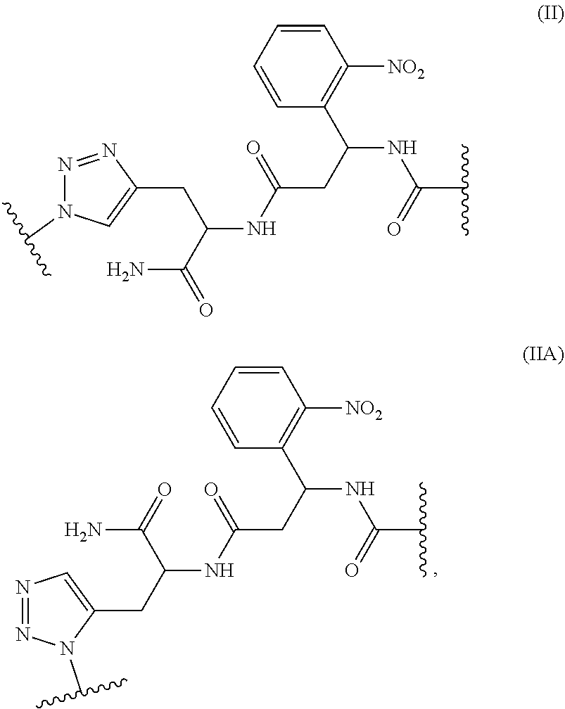


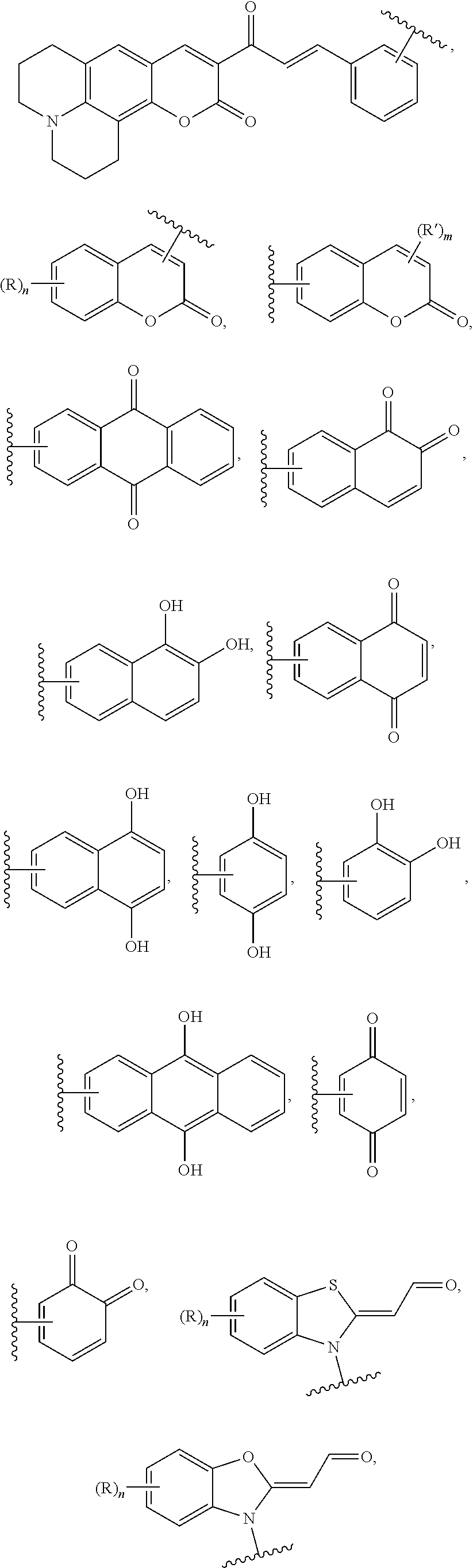
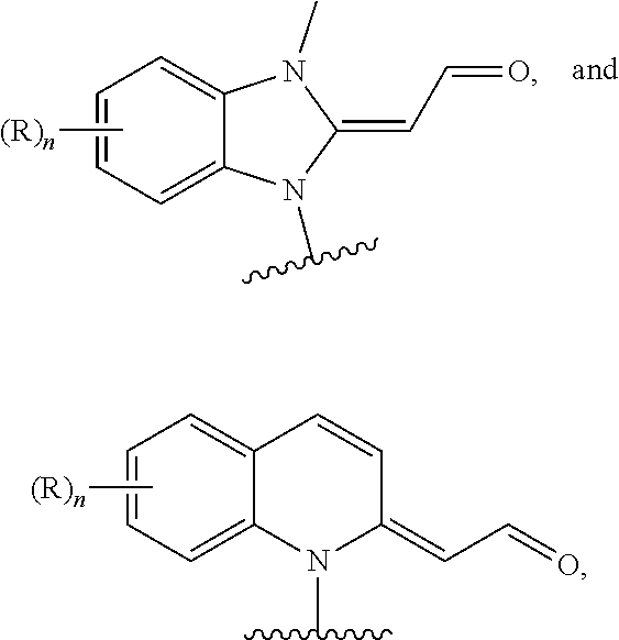


D00000

D00001

D00002

D00003

D00004

D00005
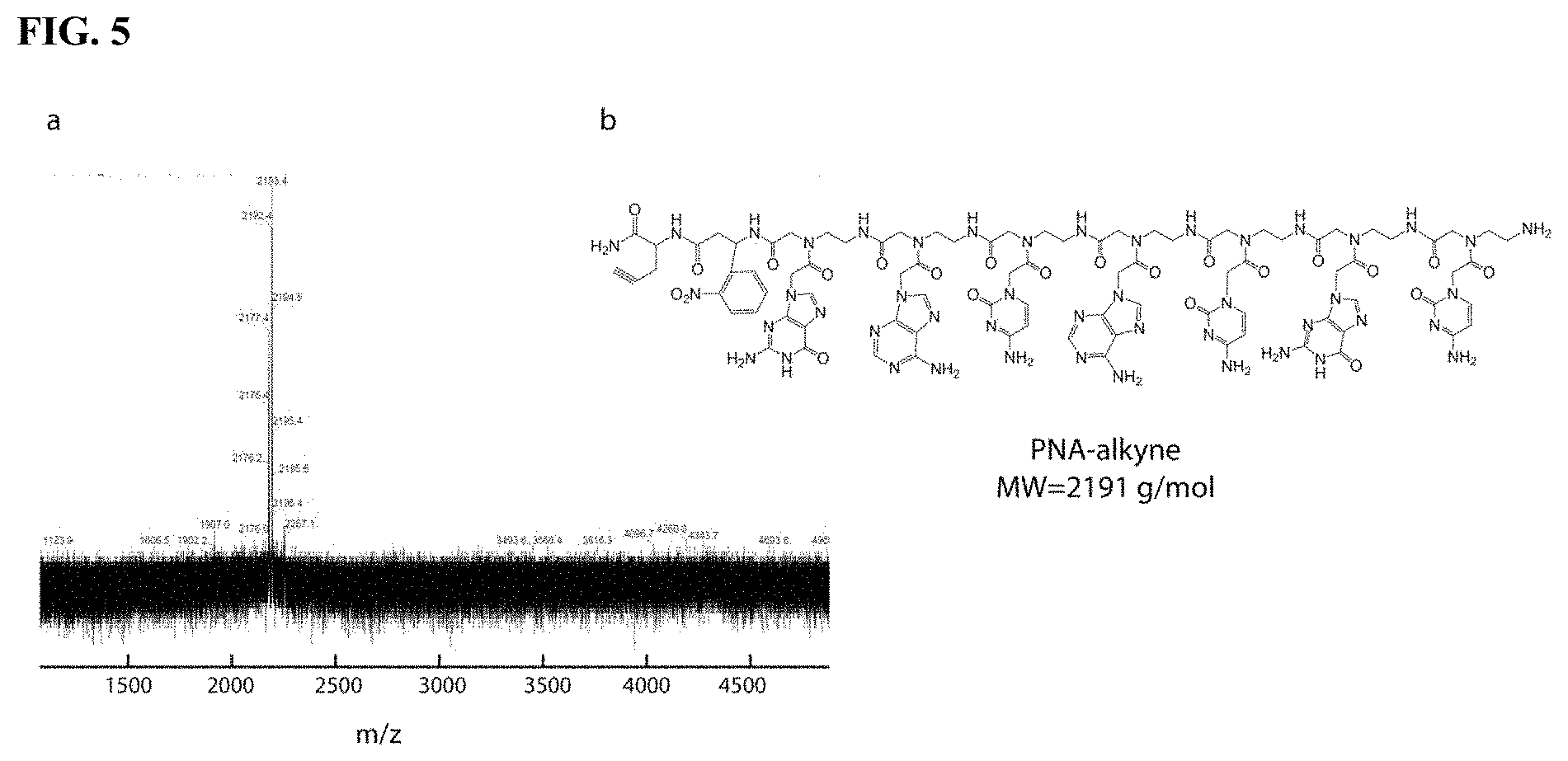
D00006
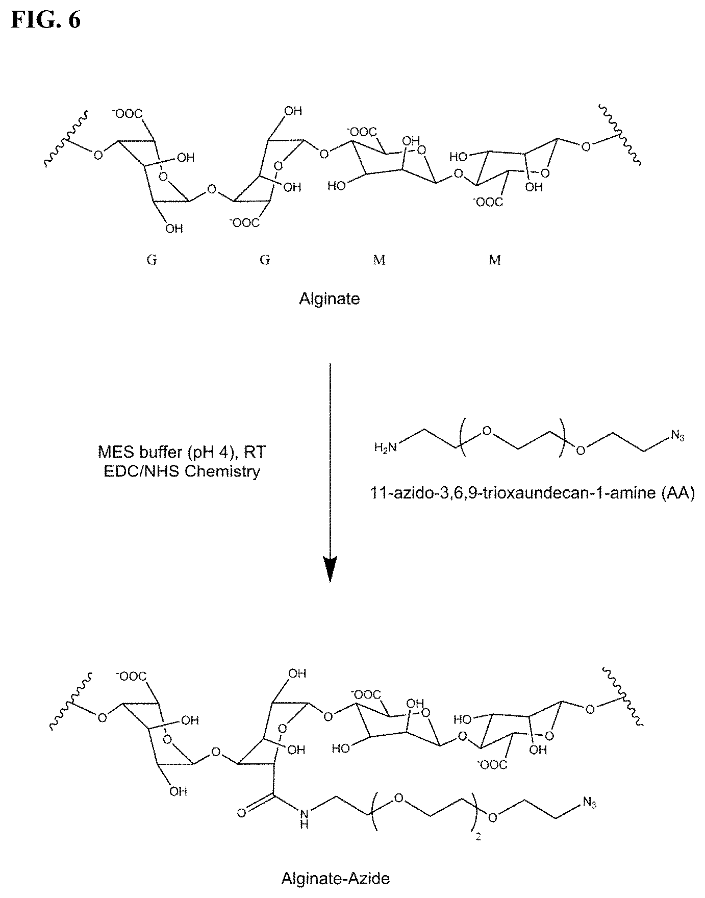
D00007

D00008

D00009

D00010
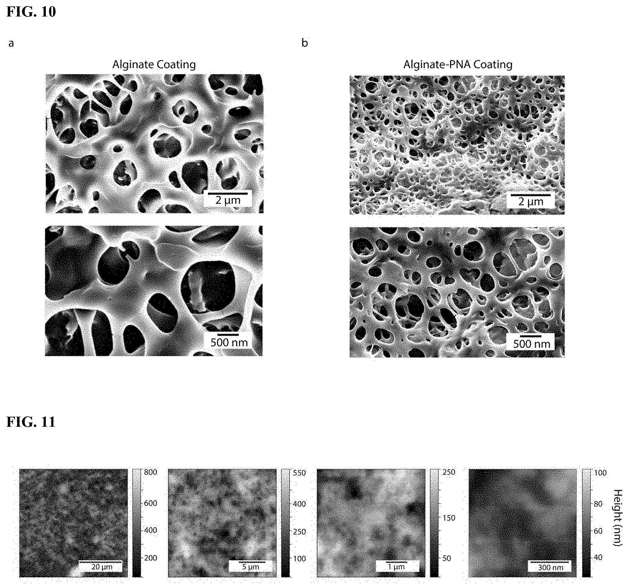
D00011

D00012

D00013

D00014


P00001

P00002

XML
uspto.report is an independent third-party trademark research tool that is not affiliated, endorsed, or sponsored by the United States Patent and Trademark Office (USPTO) or any other governmental organization. The information provided by uspto.report is based on publicly available data at the time of writing and is intended for informational purposes only.
While we strive to provide accurate and up-to-date information, we do not guarantee the accuracy, completeness, reliability, or suitability of the information displayed on this site. The use of this site is at your own risk. Any reliance you place on such information is therefore strictly at your own risk.
All official trademark data, including owner information, should be verified by visiting the official USPTO website at www.uspto.gov. This site is not intended to replace professional legal advice and should not be used as a substitute for consulting with a legal professional who is knowledgeable about trademark law.