Heat Pipe Cooled Pallet Shipper
Ahmed; Iftekhar
U.S. patent application number 16/891404 was filed with the patent office on 2020-12-03 for heat pipe cooled pallet shipper. This patent application is currently assigned to Sonoco Development, Inc.. The applicant listed for this patent is Sonoco Development, Inc.. Invention is credited to Iftekhar Ahmed.
| Application Number | 20200377279 16/891404 |
| Document ID | / |
| Family ID | 1000004884385 |
| Filed Date | 2020-12-03 |


| United States Patent Application | 20200377279 |
| Kind Code | A1 |
| Ahmed; Iftekhar | December 3, 2020 |
Heat Pipe Cooled Pallet Shipper
Abstract
A packaging system for transporting a payload while maintaining the payload within an acceptable temperature range. The payload is cooled by two sets of U-shaped heat pipes within the payload compartment. A set of cold heat pipes is cooled by a layer of phase change material located above the payload, while a set of warm heat pipes is cooled by a layer of phase change material located below the payload.
| Inventors: | Ahmed; Iftekhar; (Pierrefonds, CA) | ||||||||||
| Applicant: |
|
||||||||||
|---|---|---|---|---|---|---|---|---|---|---|---|
| Assignee: | Sonoco Development, Inc. Hartsville SC |
||||||||||
| Family ID: | 1000004884385 | ||||||||||
| Appl. No.: | 16/891404 | ||||||||||
| Filed: | June 3, 2020 |
Related U.S. Patent Documents
| Application Number | Filing Date | Patent Number | ||
|---|---|---|---|---|
| 62856203 | Jun 3, 2019 | |||
| Current U.S. Class: | 1/1 |
| Current CPC Class: | F28D 15/0233 20130101; B65D 81/18 20130101 |
| International Class: | B65D 81/18 20060101 B65D081/18; F28D 15/02 20060101 F28D015/02 |
Claims
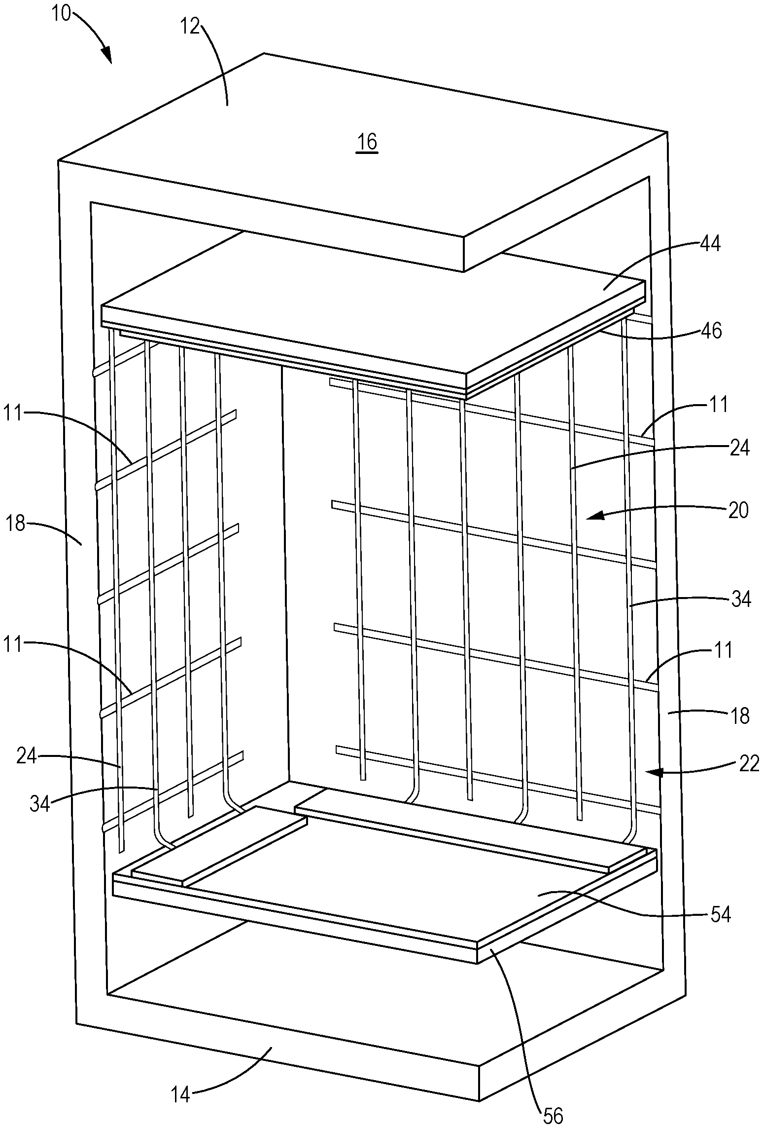
1. A packaging system 10 for shipping a temperature sensitive payload 90, the packaging system 10 comprising: a housing 12 comprising a bottom wall 14, a top wall 16 located above and in spaced vertical alignment with the bottom wall 14, and side walls 18 extending vertically between the bottom wall 14 and the top wall 16, the housing 12 defining a payload compartment 20 for holding the payload 90; a cooling system comprising one or more arrays of cold heat pipes 24, one or more arrays of warm heat pipes 34, a top layer 44 of cold phase change material (PCM) and a bottom layer 54 of warm PCM material; each array of cold heat pipes 24 located within the housing 12 and comprising one or more cold heat pipes 24, each cold heat pipe 24 shaped like an inverted "U" and comprising a horizontal section 27 connecting two downwardly extending vertical sections 26, 28; each array of warm heat pipes 34 located within the housing 12 and comprising one or more warm heat pipes 34, each warm heat pipe 34 shaped like a "U" and comprising a horizontal section 37 connecting two upwardly extending vertical sections 36, 38; a first phase change material (PCM) 29 located within each cold heat pipe 24, the first phase change material conditioned to a first temperature; a second phase change material (PCM) 39 located within each warm heat pipe 34, the second phase change material conditioned to a second temperature that is warmer than the first temperature; the top layer 44 of cold phase change material is in thermal contact with the horizontal section 27 of each cold heat pipe 24; and the bottom layer 54 of warm phase change material is in thermal contact with the horizontal section 37 of each warm heat pipe 34.
2. The packaging system 10 of claim 1 further comprising: a first thermally conductive plate 46 in thermal contact with the top layer 44 of cold phase change material.
3. The packaging system 10 of claim 2 wherein: the cold heat pipes 24 are welded to the first thermally conductive plate 46.
4. The packaging system 10 of claim 2 wherein: the cold heat pipes 24 are embedded in the first thermally conductive plate 46.
5. The packaging system 10 of claim 1 further comprising: a second thermally conductive plate 56 in thermal contact with the bottom layer 54 of warm phase change material.
6. The packaging system 10 of claim 5 wherein: the warm heat pipes 34 are welded to the second thermally conductive plate 56.
7. The packaging system 10 of claim 5 wherein: the warm heat pipes 34 are embedded in the second thermally conductive plate
56.
8. The packaging system 10 of claim 1 wherein: the vertical sections 26, 28, 36, 38 of each heat pipe 24, 34 has an inner surface 49 that defines grooves 58 to facilitate capillary flow of the phase change material in a condensed state.
9. A packaging system 110 for shipping a temperature sensitive payload 90, the packaging system 110 comprising: a housing 112 comprising an internal wall 122 separating a payload compartment 120 from a refrigerant compartment 121; a cooling system comprising an array of heat pipes 124 arranged in a parallel array, the array of heat pipes 124 located within the housing 112, each heat pipe 124 comprising a lower horizontal section 126 having an end located in the refrigerant compartment 121, an upper horizontal section located in the payload compartment 120 and a vertical section 127 connecting the lower horizontal section 126 to the upper horizontal section 128; and a refrigerant 144 comprising one or more phase change bottles, the refrigerant 144 located in the refrigerant compartment 121 adjacent to and in thermal contact with the lower horizontal heat pipe section 126.
Description
BACKGROUND OF THE INVENTION
Field of the Invention
[0001] This disclosure relates to a packaging system for transporting a payload while maintaining the payload within an acceptable temperature range. More particularly, this disclosure relates to a packaging system for transporting a payload wherein the payload is cooled by two sets of heat pipes that run along the interior walls of the payload compartment.
Description of the Related Art
[0002] Currently the shipment of temperature controlled products is achieved through the use of insulated packaging that contains a large amount of conditioned phase change materials, typically in the form a bottles filled with the phase change material ("PCM bottles"). Usually the PCM bottles are single use materials and are not practicable for reuse. Also, the use of PCM bottles can result in unwanted temperature gradients (changes) within the payload area.
[0003] The present disclosure is intended to address these issues.
BRIEF SUMMARY OF THE INVENTION
[0004] The present disclosure generally relates to a packaging system for transporting a payload while maintaining the payload within an acceptable temperature range. The payload is cooled by two sets of heat pipes that run along the interior walls of the payload compartment. A set of cold heat pipes is cooled by a layer of phase change material located above the payload, while a set of warm heat pipes is cooled by a layer of phase change material located below the payload.
[0005] In one aspect the disclosure relates to a packaging system comprising a housing, a temperature control system comprising at least two arrays of heat pipes and layers of phase change material in thermal contact with the heat pipes.
[0006] The housing may comprising a bottom wall, a top wall located above and in spaced vertical alignment with the bottom wall, and side walls extending vertically between the bottom wall and the top wall. The housing defines a payload compartment for holding a payload.
[0007] The temperature control system comprises one or more arrays of cold heat pipes, one or more arrays of warm heat pipes, a top layer of cold phase change material (PCM) and a bottom layer of warm PCM material. The payload is cooled or warmed by the heat pipes that run along the interior walls of the payload compartment.
[0008] Each array of cold heat pipes is located within the housing and comprises one or more cold heat pipes. Preferably, each cold heat pipe is shaped like an inverted "U" and comprises a horizontal section connecting two downwardly extending vertical sections. A first "cold" phase change material is located within each cold heat pipe and is conditioned to a first temperature. The top layer of cold phase change material is in thermal contact with the horizontal section of each cold heat pipe.
[0009] Similarly, each array of warm heat pipes is located within the housing and comprises one or more warm heat pipes. Preferably, each warm heat pipe is shaped like a "U" and comprises a horizontal section connecting two upwardly extending vertical sections. A second "warm" phase change material is located within each warm heat pipe and is conditioned to a second temperature that is warmer than the first temperature. The bottom layer of warm phase change material is in thermal contact with the horizontal section of each warm heat pipe.
[0010] In another aspect a packaging system is described comprising a housing, a cooling system and a refrigerant. The housing comprises an internal wall separating a payload compartment from a refrigerant compartment. The cooling system comprises an array of heat pipes arranged in a parallel array, the array of heat pipes located within the housing. Each heat pipe comprises a lower horizontal section having an end located in the refrigerant compartment, an upper horizontal section located in the payload compartment and a vertical section connecting the lower horizontal section to the upper horizontal section. The lower horizontal section functions as the evaporation section and the higher horizontal section functions as the condensation section of the heat pipes. The refrigerant comprises one or more phase change bottles located in the refrigerant compartment adjacent to and in thermal contact with the lower horizontal heat pipe section.
BRIEF DESCRIPTION OF THE DRAWINGS
[0011] FIG. 1 is cutaway perspective view of a quarter portion of a packaging system according to the disclosure.
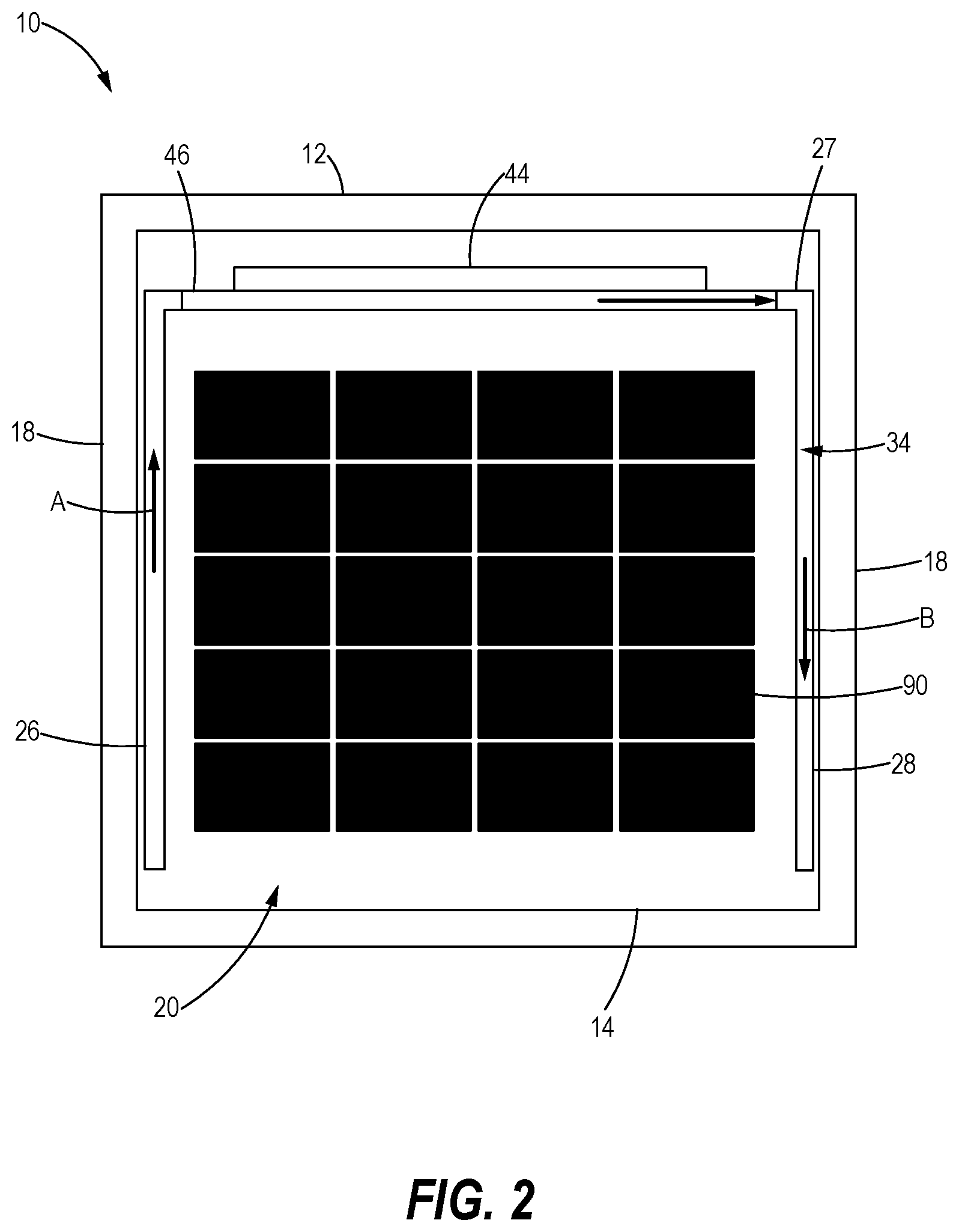
[0012] FIG. 2 is a cutaway front view of a packaging system according to the disclosure.
[0013] FIG. 3 is a cutaway perspective view of a heat pipe according to the disclosure.
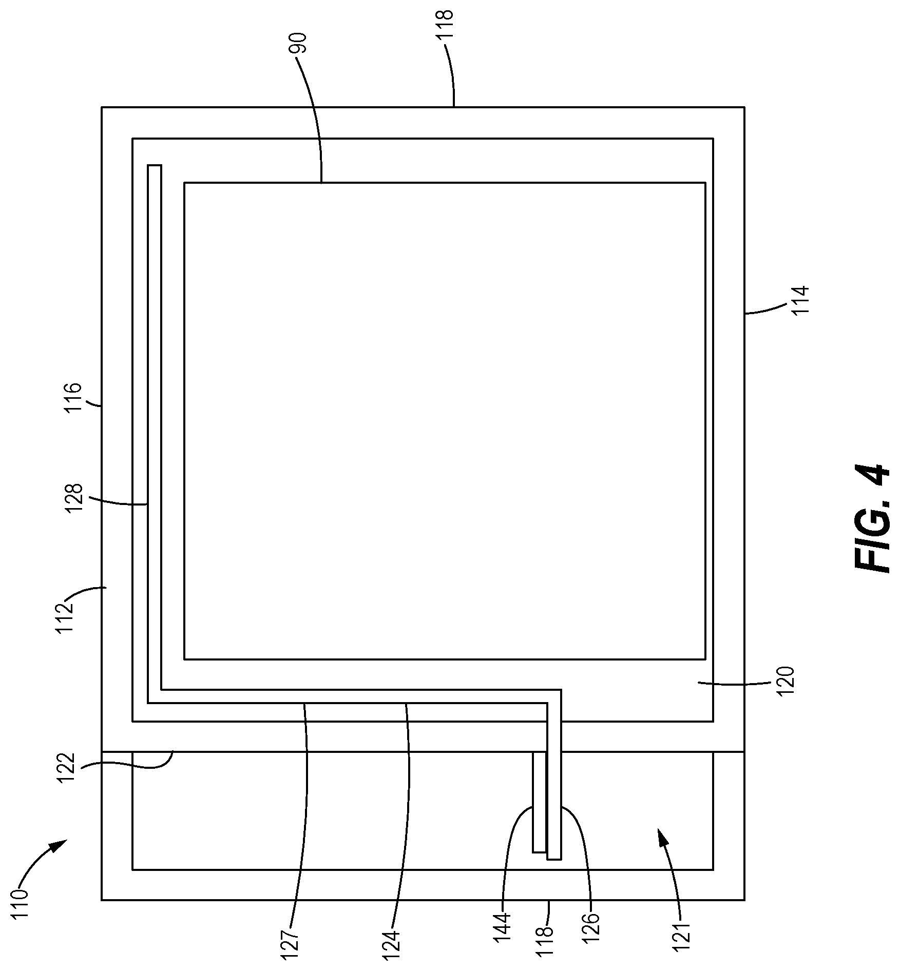
[0014] FIG. 4 is cutaway front view of an alternative packaging system according to the disclosure.
DETAILED DESCRIPTION OF THE INVENTION
[0015] While the invention described herein may be embodied in many forms, there is shown in the drawings and will herein be described in detail one or more embodiments with the understanding that this disclosure is to be considered an exemplification of the principles of the invention and is not intended to limit the disclosure to the illustrated embodiments. Aspects of the different embodiments can be combined with or substituted for one another.
[0016] As will be appreciated, terms such as "above" and "below", "upper" and "lower", "top" and "bottom," "front" and "back," (etc.), used as nouns, adjectives or adverbs refer in this description to the orientation of the structure of the wrapper as it is illustrated in the cross sectional views. Such terms are not intended to limit the invention to a particular orientation.
[0017] As used herein the term "warm heat pipes" means that the PCM in the heat pipes is conditioned to a temperature that is warmer then the PCM in the cold heat pipes. For example, the cold PCM may be conditioned to a temperature of, say, 5 degrees C. and the warm PCM may be conditioned to a temperature of 23 degrees C. (i.e., room temperature).
[0018] The disclosure relates to a packaging system for transporting a payload while maintaining the payload within an acceptable temperature range. The payload may be cooled or warmed by two sets of U-shaped heat pipes that run along the interior walls of the payload compartment. A set of cold heat pipes is cooled by a layer of phase change material located above the payload, while a set of warm heat pipes is cooled by a layer of phase change material located below the payload. The entire cooling process is "passive", meaning it does not require a battery or other electrical power.
[0019] FIG. 1 is a perspective view of a quarter portion of a packaging system 10 according to the invention. The system 10 comprises a housing 12 defining a payload compartment 20 for holding a payload 90 (shown in FIG. 2) and a cooling system to help maintain the payload 90 within an acceptable temperature range.
[0020] The housing may comprise a bottom wall 14, a top wall 16 located above and in spaced vertical alignment with the bottom wall 14, and side walls 18 extending vertically between the bottom wall 14 and the top wall 16.
[0021] The cooling system comprises one or more arrays of cold heat pipes 24, one or more arrays of warm heat pipes 34, a top layer 44 of cold PCM material and a bottom layer 54 of warm PCM material.
Two Sets of Heat Pipes
[0022] The cold heat pipes 24 and the warm heat pipes 34 circulate phase change materials (PCMs) throughout the payload compartment 20 and preferably along the interior walls of the housing 12.
[0023] Preferably, each cold heat pipe 24 is shaped like an inverted "U" and comprises a horizontal section 27 connecting two downwardly extending legs or vertical sections 26, 28. The cold heat pipes 24 may be arranged in a first parallel array and a second parallel array orthogonal to the first parallel array so that they contact all four sides of the housing 12. The cold heat pipes 24 may be secured to the sides 18 of the housing 12 with cross braces 11 or by any suitable means. The cold heat pipes 24 may be made of a thermally conductive material such as aluminum or copper, and contain a cold phase change material. A first "cold" phase change material (PCM) 29 is located within each cold heat pipe 24.
[0024] Preferably, each warm heat pipe 34 may be shaped like a right-side-up "U", and comprise a horizontal section 37 connecting two vertical sections 36, 38. The warm heat pipes 34 may be arranged in a first parallel array and a second parallel array orthogonal to the first parallel array so that they too contact all four sides 18 of the housing 12. The warm heat pipes 34 may be secured to the sides of the container with cross braces 11 or by any suitable means. The warm heat pipes 34 may be made of a thermally conductive material such as aluminum or copper, and contain a warm phase change material. A second "warm" phase change material (PCM) 39 is located within each warm heat pipe 34.
Phase Change Material Layers
[0025] The first (or top) layer of cold PCM material 44 may comprise one or more cold phase change bottles and may be located above and in thermal contact with the horizontal section 27 of each cold heat pipe 24 to act as a heat sink. The cold phase change bottles that make up the cold PCM layer 44 may contain a cold phase change material (such as water), preferably conditioned to a freezing temperature.
[0026] The second (or bottom) layer of warm PCM 54 may comprise one or more warm phase change bottles and may be located above and in thermal contact with the horizontal sections 37 of the warm heat pipes 34. The warm phase change bottles that make up the warm PCM layer 54 may contain a warm phase change material preferably conditioned to a second freezing temperature that is warmer than the cold PCM freezing temperature. For example, if the cold phase change material is conditioned to a temperature of, say, 5 degree C., the warm phase change material may be conditioned to a freezing temperature of 23 degree C.
[0027] Thus, in the example above, the first "cold" PCM 29 changes phases (freezes) at 5 C (41 F) and the second "warm" PCM 39 changes phases (freezes) at 23 C (72 F).
[0028] In another example, a packaging system 10 for maintain a payload 90 at temperature between 15 C (59 F) and 25 C (77 F) may comprise a first "cold" PCM 29 that changes phases (freezes) at a temperature close to 15 C (such as 17 C) and a second "warm" PCM 39 that changes phases (freezes) at a temperature close to 25 C (such as 23 C). Thus the second PCM 39 freezes at a temperature above the freezing temperature of the first PCM 29.
[0029] Phase change bottles typically are rigid structures that contain a phase change material. The phase change material may be a liquid, a solution, a gel, a semi-solid or any suitable form of phase change material.
[0030] Instead of phase change bottles, the first (or top) layer of cold PCM material 44 and/or the second (or bottom) layer of warm PCM 54 may comprise any suitable containment device or devices. For example, the first (or top) layer of cold PCM material 44 and/or the second (or bottom) layer of warm PCM 54 may comprise one or more phase change bricks (i.e., structures comprising a porous core such as expanded foam, typically having a three dimensional brick-like shape, saturated with a phase change material and wrapped in an envelope typically made of polyethylene film).
Thermally Conductive Plates
[0031] The system 10 may further comprise a first (top) thermally conductive plate 46 of metal or nonmetal. The top plate 46 should be in thermal and/or physical contact with the cold phase change layer 44 and the cold heat pipes 24 to facilitate the transfer of thermal energy between the cold phase change layer 44 and the cold heat pipes 24. For example, the cold heat pipes 24 may be welded to the plate 46 or they may be embedded (pass through channels) in the plate 46.
[0032] The system 10 may further comprise a second (bottom) warm thermally conductive plate 56. The bottom plate 56 may be metal or nonmetal. The bottom plate 56 should be in thermal and/or physical contact with the warm phase change bottles 54 and the warm heat pipes 34 to facilitate the transfer of thermal energy between the warm phase change bottles 54 and the warm heat pipes 34. For example, the warm heat pipes 34 may be welded to the plate 56 or they may pass through channels in the plate 56.
Principle of Operation
[0033] In general, heat pipes are enclosed pipes, sealed at both ends, that contain a fluid that transfers heat (to or from the heat pipe) via the heating and cooling of the fluid. In absorbing or transferring heat, the fluid may undergo a phase change. For example, the fluid may change from a liquid to a gas upon absorbing heat and then change back to a liquid upon giving off heat. The liquid may flow through the pipe due to gravity or some sort of wicking or capillary action.
[0034] FIG. 2 is a cross-sectional schematic view of the system 10 showing one cold heat pipe 24. Heat passing through the container sidewalls 18 is absorbed by the first PCM 29 inside the first and second vertical sections 26, 28 of the cold heat pipe 24 (i.e., the "legs" of the inverted "U"). As the first liquid PCM inside the vertical sections 26, 28 is heated, the liquid PCM will start evaporating. As the first PCM liquid evaporates it will remain at about its evaporation temperature, and thus help maintain the temperature of the cold heat pipe 24 at the phase change temperature of the first "cold" PCM 29, say, 5 C. As the first "cold" PCM 29 evaporates, it will rise through the vertical sections 26, 28 of the cold heat pipe 24 due to its lower density. For example, the evaporated first PCM 29 in the first vertical section 26 will rise in the direction of arrow A. Likewise, the evaporated first PCM 29 in the other vertical section 28 will rise in the same upward direction.
[0035] The evaporated first PCM 29 rises until it enters the horizontal section 27 of the cold heat pipe 24. There, the first PCM 29 inside the cold heat pipe 24 begins to condense as it is cooled by the layer of cold PCM bottles 44. As the first PCM 29 inside the cold heat pipe 24 condenses it transfers thermal energy to the layer of cold PCM material 44 (e.g. PCM bottles 44) while maintaining a constant temperature, which also helps maintain the payload compartment at a constant temperature. At the same time, the cold PCM material 44 will start melting.
[0036] The condensed liquid first PCM 29 inside the cold heat pipe 24 trickles down one or both of the vertical sections 26, 28 of the cold heat pipe 24, for example, in the direction of down arrow B in FIG. 2. The condensed liquid first PCM 29 may flow down due to gravity and/or capillary action. The evaporation/condensation process then begins again, as the liquid first PCM 29 in the vertical sections 26, 28 begins to evaporate again.
[0037] Thus, by going through a liquid-gas-liquid cycle, the first "cold" PCM 29 helps maintain a narrow temperature range within the payload compartment 20 as it circulates within each cold heat pipe 24. This process continues until the phase change material in the layer of cold PCM material 44 has been exhausted. The layer of cold PCM material 44 is the only component of the system 10 that needs to be replaced or reconditioned at the end of a shipping operation.
[0038] In a similar fashion, evaporated second "warm" PCM 39 in the first and second vertical sections 36, 38 of the warm heat pipes 34 will start to liquefy as it is cooled. As the second PCM 39 inside the vertical sections 36, 38 is cooled, the liquid second PCM 39 will begin to trickle down one or both of the vertical sections 36, 38 of the warm heat pipe 34. When the warmed second PCM 39 contacts the layer of warm PCM material 54 it will begin to evaporate and the warm PCM material 54 will start melting. As the second PCM 39 evaporates it will remain at about its evaporation temperature, and thus help maintain the temperature of the warm heat pipe 34 at the phase change temperature of the second PCM 39, say, room temperature (about 22 C). As the second PCM 39 evaporates, it will rise through the vertical sections of the warm heat pipe 34, where the cycle will begin again. Thus, by going through a liquid-gas-liquid cycle, the second PCM 39 maintains a somewhat constant temperature as it circulates within the warm heat pipe 34. In this way a closed phase change cycle is setup for warming the payload 90. This process continues until the PCM in the layer of warm PCM material 54 has been exhausted.
Liquid PCM May Move Within the Heat Pipes Via Capillary Action
[0039] FIG. 3 is a perspective view of a section of a cold heat pipe 24 showing an inner surface 49 with ridges 48. The ridges 48 define grooves 50 that encourage capillary action that helps the liquid first PCM 29 flow down the pipe 24. First PCM 29 vapor or gas may travel up the pipe 24 via a center channel 52. The warm heat pipes 34 may have similar ridges 48 and grooves 50.
Alternative Embodiment
[0040] FIG. 4 is cutaway front view of an alternative packaging system 110 according to the disclosure. The system 110 comprises a housing 112 defining a payload compartment 120 for holding a payload 90 and a cooling system to help maintain the payload 90 within an acceptable temperature range.
[0041] The housing 112 may comprise a bottom wall 114, a top wall 116 located above and in spaced vertical alignment with the bottom wall 114, and side walls 118 extending vertically between the bottom wall 114 and the top wall 116. An internal wall 122 may separate a payload compartment 120 from a refrigerant compartment 121.
[0042] The cooling system comprises one or more arrays of cold and/or warm heat pipes 124, and one or more refrigerants 144. Instead of a U-shape, the heat pipes 124 may have any suitable shape, such as the S-shape shown in FIG. 4.
[0043] Each heat pipe 124 may comprise a lower horizontal section 126 having an end located in the refrigerant compartment 121, an upper horizontal section located in the payload compartment 120 and a vertical section 127 connecting the lower horizontal section 126 to the upper horizontal section 128. The first or lower horizontal section 126 functions as the condensation section and the second or higher horizontal section 128 functions as the evaporation section of the heat pipe 124. A first refrigerant 144 may be located in the refrigerant compartment 121 adjacent to and in thermal contact with the first horizontal heat pipe section 126 to act as an evaporator. The first refrigerant 144 may comprise one or more phase change bottles.
[0044] When the phase change material circulating through the heat pipe 124 reaches the lower section 126, it evaporates to form a gas and begins to rise through the heat pipe 124 until it reaches the upper horizontal section 128. When the phase change material reaches the upper section 128, it condenses and begins to flow downward through the heat pipe 124 until it reaches the lower horizontal section 126.
[0045] Optionally, a second array of heat pipes and a second refrigerant (not shown) may be used. The second array of heat pipes may be charged with a second phase change material having a phase change temperature different that that the of the first array 124.
[0046] Thus, in one embodiment, a plurality of cold heat pipes are arranged in a first parallel array and a plurality of warm heat pipes are arranged in a second parallel array orthogonal to the first parallel array, preferably with both sets of heat pipes contacting all four sides of the housing 112. The cold heat pipes and the warm heat pipes may be secured to the side walls 116 and, where needed, to the top wall 114, with cross braces (not shown) or by any suitable means.
[0047] It is understood that the embodiments of the invention described above are only particular examples which serve to illustrate the principles of the invention. Modifications and alternative embodiments of the invention are contemplated which do not depart from the scope of the invention as defined by the foregoing teachings and appended claims. It is intended that the claims cover all such modifications and alternative embodiments that fall within their scope.
* * * * *
D00000
D00001
D00002
D00003
D00004
XML
uspto.report is an independent third-party trademark research tool that is not affiliated, endorsed, or sponsored by the United States Patent and Trademark Office (USPTO) or any other governmental organization. The information provided by uspto.report is based on publicly available data at the time of writing and is intended for informational purposes only.
While we strive to provide accurate and up-to-date information, we do not guarantee the accuracy, completeness, reliability, or suitability of the information displayed on this site. The use of this site is at your own risk. Any reliance you place on such information is therefore strictly at your own risk.
All official trademark data, including owner information, should be verified by visiting the official USPTO website at www.uspto.gov. This site is not intended to replace professional legal advice and should not be used as a substitute for consulting with a legal professional who is knowledgeable about trademark law.