Mobile Robot Morphology
Berkowitz; Ben ; et al.
U.S. patent application number 16/884873 was filed with the patent office on 2020-12-03 for mobile robot morphology. The applicant listed for this patent is X Development LLC. Invention is credited to Sarah Bates, Ben Berkowitz, Matthew Day, Nicholas Foster, Chris Jones, Gregory Katz, Christopher Morey, Philip Mullins, Vincent Nabat, Mario Prats, Justine Rembisz, Joshua Seal, Jonathan Souliere, Marc Strauss, John Tran, Robert Wilson.
| Application Number | 20200376656 16/884873 |
| Document ID | / |
| Family ID | 1000004871845 |
| Filed Date | 2020-12-03 |


View All Diagrams
| United States Patent Application | 20200376656 |
| Kind Code | A1 |
| Berkowitz; Ben ; et al. | December 3, 2020 |
Mobile Robot Morphology
Abstract
In an embodiment, a mobile robotic device includes a mobile base and a mounting column fixed to the mobile base. The robotic device further includes a seven-degree-of-freedom (7DOF) robotic arm, including a rotatable joint that enables rotation of the 7DOF robotic arm relative to the mounting column. The robotic device additionally includes a perception housing comprising at least one sensor, where the mounting column, the rotatable joint of the 7DOF arm, and the perception housing are arranged in a stacked tower such that the rotatable joint of the 7DOF arm is above the mounting column and below the perception housing.
| Inventors: | Berkowitz; Ben; (San Francisco, CA) ; Rembisz; Justine; (San Carlos, CA) ; Nabat; Vincent; (San Francisco, CA) ; Seal; Joshua; (San Jose, CA) ; Katz; Gregory; (San Francisco, CA) ; Jones; Chris; (San Francisco, CA) ; Foster; Nicholas; (Oakland, CA) ; Morey; Christopher; (Mountain View, CA) ; Tran; John; (Mountain View, CA) ; Strauss; Marc; (Fremont, CA) ; Mullins; Philip; (San Francisco, CA) ; Souliere; Jonathan; (Redwood City, CA) ; Bates; Sarah; (Palo Alto, CA) ; Day; Matthew; (Oakland, CA) ; Wilson; Robert; (Pacifica, CA) ; Prats; Mario; (Los Gatos, CA) | ||||||||||
| Applicant: |
|
||||||||||
|---|---|---|---|---|---|---|---|---|---|---|---|
| Family ID: | 1000004871845 | ||||||||||
| Appl. No.: | 16/884873 | ||||||||||
| Filed: | May 27, 2020 |
Related U.S. Patent Documents
| Application Number | Filing Date | Patent Number | ||
|---|---|---|---|---|
| 62853534 | May 28, 2019 | |||
| Current U.S. Class: | 1/1 |
| Current CPC Class: | B25J 5/007 20130101; B25J 9/162 20130101; B25J 9/0096 20130101; B25J 9/1697 20130101; B25J 17/00 20130101; B25J 15/0028 20130101; B25J 17/02 20130101 |
| International Class: | B25J 9/16 20060101 B25J009/16; B25J 5/00 20060101 B25J005/00; B25J 9/00 20060101 B25J009/00; B25J 17/00 20060101 B25J017/00; B25J 17/02 20060101 B25J017/02; B25J 15/00 20060101 B25J015/00 |
Claims
1. A mobile robotic device comprising: a mobile base; a mounting column fixed to the mobile base; a seven-degree-of-freedom (7DOF) robotic arm, comprising a rotatable joint that enables rotation of the 7DOF robotic arm relative to the mounting column; and a perception housing comprising at least one sensor, wherein the mounting column, the rotatable joint of the 7DOF arm, and the perception housing are arranged in a stacked tower such that the rotatable joint of the 7DOF arm is above the mounting column and below the perception housing.
2. The mobile robotic device of claim 1, further comprising at least one drive wheel, wherein the stacked tower is positioned above the at least one drive wheel.
3. The mobile robotic device of claim 1, wherein the mounting column is attached at a front end of the mobile base, wherein the mobile base further comprises a top surface positioned at a rear end of the mobile base.
4. The mobile robotic device of claim 3, wherein the top surface of the mobile base comprises a container for storing objects moved by the 7DOF robotic arm.
5. The mobile robotic device of claim 1, wherein the 7DOF robotic arm is configured to fold into a stowed configuration, wherein the 7DOF robotic arm is contained within a footprint of the mobile base when the 7DOF robotic arm is in the stowed configuration.
6. The mobile robotic device of claim 1, wherein the rotatable joint is a shoulder yaw J0 joint, wherein the 7DOF robotic arm further comprises a shoulder pitch J1 joint, a bicep roll J2 joint, an elbow pitch J3 joint, a forearm roll J4 joint, a wrist pitch J5 joint, and a wrist roll J6 joint.
7. The mobile robotic device of claim 6, wherein a first offset between the shoulder yaw J0 joint and a bicep roll J2 joint is approximately equal to a second offset between the bicep roll J2 joint and the forearm roll J4 joint.
8. The mobile robotic device of claim 6, wherein a first length of a bicep of the 7DOF robotic arm is approximately equal to a second length of a forearm of the 7DOF robotic arm.
9. The mobile robotic device of claim 6, wherein the 7DOF robotic arm is configured to fold into a shoulder up stowed configuration, the shoulder up stowed configuration comprising the shoulder yaw J0 joint being rotated toward a rear end of the mobile base, the shoulder pitch J1 joint being rotated vertical up, the elbow pitch J3 joint being rotated vertical down, and the wrist pitch J5 joint being rotated vertical down.
10. The mobile robotic device of claim 9, wherein when in the shoulder up stowed configuration, the 7DOF robotic arm overhangs the mobile base such that a rearmost point of the 7DOF robotic arm is approximately aligned with the rear end of the mobile base.
11. The mobile robotic device of claim 6, wherein the 7DOF robotic arm is configured to fold into a shoulder down stowed configuration, the shoulder down stowed configuration comprising the shoulder yaw J0 joint being rotated toward a rear end of the mobile base, the shoulder pitch J1 joint being rotated vertical down, the elbow pitch J3 joint being rotated vertical up, and the wrist pitch J5 joint being rotated vertical up.
12. The mobile robotic device of claim 6, wherein when the shoulder yaw J0 joint is rotated opposite a front end of the mobile base to which the mounting column is fixed and the shoulder pitch J1 joint is rotated vertical down, a bottommost point of a bicep of the 7DOF robotic arm is above a top surface of the mobile base.
13. The mobile robotic device of claim 6, wherein the stacked tower further comprises a mast between the rotatable joint and the perception housing, wherein the mast has a length such that when the shoulder pitch J1 joint is rotated vertical up, a topmost point of a bicep of the 7DOF robotic arm is approximately aligned with a top of the mast, wherein the length of the mast is sufficient to prevent collision between the perception housing and the 7DOF robotic arm when the shoulder pitch J1 joint is rotated vertical up.
14. The mobile robotic device of claim 6, wherein each joint of the 7DOF robotic arm has a range of motion which is optimized for a right handed elbow up position in which the shoulder yaw J0 joint is rotated toward a right side of the mobile base, the shoulder pitch J1 joint is rotated vertical up, the elbow pitch J3 joint is rotated vertical up, and the wrist pitch J5 joint is rotated vertical up.
15. The mobile robotic device of claim 6, wherein the 7DOF robotic arm comprises an end effector, wherein the 7DOF robotic arm is configured to enable a line of sight between the at least one sensor of the perception housing and the end effector by rotating the bicep roll J2 joint.
16. The mobile robotic device of claim 1, wherein the 7DOF robotic arm comprises an end effector, wherein the 7DOF robotic arm is configured to enable a line of sight between the at least one sensor of the perception housing and the end effector at a set of target heights, the set of target heights spanning a range that includes the end effector positioned proximate to a ground floor, the end effector positioned at a height of the mounting column, and the end effector positioned at a height of the perception housing.
17. The mobile robotic device of claim 1, wherein the rotatable joint that enables rotation of the 7DOF robotic arm relative to the mounting column has a range of motion that excludes an angle in front of the mobile robotic device.
18. A robotic arm comprising a shoulder yaw J0 joint, a shoulder pitch J1 joint, a bicep roll J2 joint, an elbow pitch J3 joint, a forearm roll J4 joint, a wrist pitch J5 joint, and a wrist roll J6 joint, wherein a first offset between the shoulder yaw J0 joint and a bicep roll J2 joint is approximately equal to a second offset between the bicep roll J2 joint and the forearm roll J4 joint, and wherein the bicep is approximately equal in length to the forearm.
19. A method comprising: causing a shoulder yaw J0 joint of a 7DOF robotic arm of a mobile robotic device to rotate away from a first end of a mobile base to which a mounting column is fixed, wherein the mounting column, the shoulder yaw J0 joint of the 7DOF arm, and a perception housing of the mobile robotic device are arranged in a stacked tower such that the shoulder yaw J0 joint of the 7DOF arm is above the mounting column and below the perception housing; causing a shoulder pitch J1 joint of the 7DOF robotic arm of the mobile robotic device to rotate vertical up; causing an elbow pitch J3 joint to rotate vertical down; and causing a wrist pitch J5 joint to rotate vertical down to position the 7DOF robotic arm in a shoulder up stowed configuration.
20. The method of claim 19, wherein the mounting column is mounted to a front end of the mobile base over at least one drive wheel of the mobile robotic device, the method further comprising causing the at least one drive wheel of the mobile robotic device to navigate the mobile robotic device forward while the 7DOF robotic arm is in the shoulder up stowed configuration over a rear end of the mobile base.
21. The method of claim 20, further comprising: stopping navigation of the mobile robotic device; causing the 7DOF robotic arm to manipulate an object in front of the mobile robotic device; returning the 7DOF robotic arm to the shoulder up stowed configuration; and subsequently causing the at least one drive wheel to navigate the mobile robotic device forward while the 7DOF robotic arm is in the shoulder up stowed configuration over the rear end of the mobile base.
22. A mobile robotic device comprising: a mobile base; a mounting column fixed to the mobile base; a rotatable joint that enables rotation of an appendage relative to the mounting column; and a perception housing comprising at least one sensor, wherein the mounting column, the rotatable joint, and the perception housing are arranged in a stacked tower such that the rotatable joint is above the mounting column and below the perception housing.
Description
CROSS-REFERENCE TO RELATED APPLICATIONS
[0001] The present application claims priority to U.S. provisional application No. 62/853,534 filed on May 28, 2019 and entitled "Mobile Robot Morphology" which is herein incorporated by reference as if fully set forth in this description.
BACKGROUND
[0002] As technology advances, various types of robotic devices are being created for performing a variety of functions that may assist users. Robotic devices may be used for applications involving material handling, transportation, welding, assembly, and dispensing, among others. Over time, the manner in which these robotic systems operate is becoming more intelligent, efficient, and intuitive. As robotic systems become increasingly prevalent in numerous aspects of modern life, it is desirable for robotic systems to be efficient. Therefore, a demand for efficient robotic systems has helped open up a field of innovation in actuators, movement, sensing techniques, as well as component design and assembly.
SUMMARY
[0003] Example embodiments involve a mobile robot that is optimized for arm range of motion, space utilization, efficient arm stowing, and occlusion avoidance between a perception system and an end of arm system.
[0004] In an embodiment, a mobile robotic device includes a mobile base and a mounting column fixed to the mobile base. The robotic device further includes a seven-degree-of-freedom (7DOF) robotic arm, including a rotatable joint that enables rotation of the 7DOF robotic arm relative to the mounting column. The robotic device additionally includes a perception housing comprising at least one sensor, where the mounting column, the rotatable joint of the 7DOF arm, and the perception housing are arranged in a stacked tower such that the rotatable joint of the 7DOF arm is above the mounting column and below the perception housing.
[0005] In another embodiment, a robotic arm comprises a shoulder yaw J0 joint, a shoulder pitch J1 joint, a bicep roll J2 joint, an elbow pitch J3 joint, a forearm roll J4 joint, a wrist pitch J5 joint, and a wrist roll J6 joint, where a first offset between the shoulder yaw J0 joint and a bicep roll J2 joint is approximately equal to a second offset between the bicep roll J2 joint and the forearm roll J4 joint, and where the bicep is approximately equal in length to the forearm.
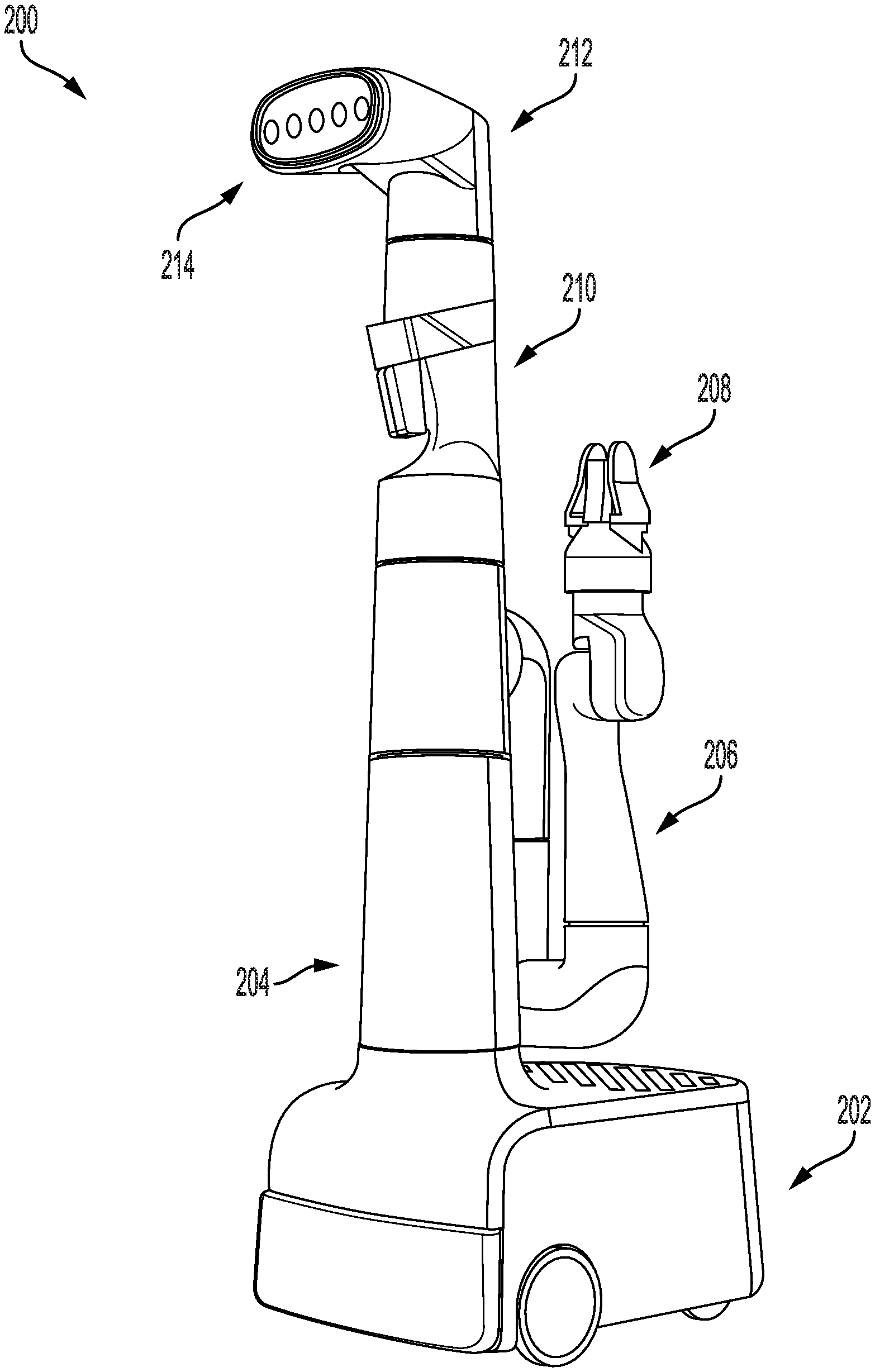
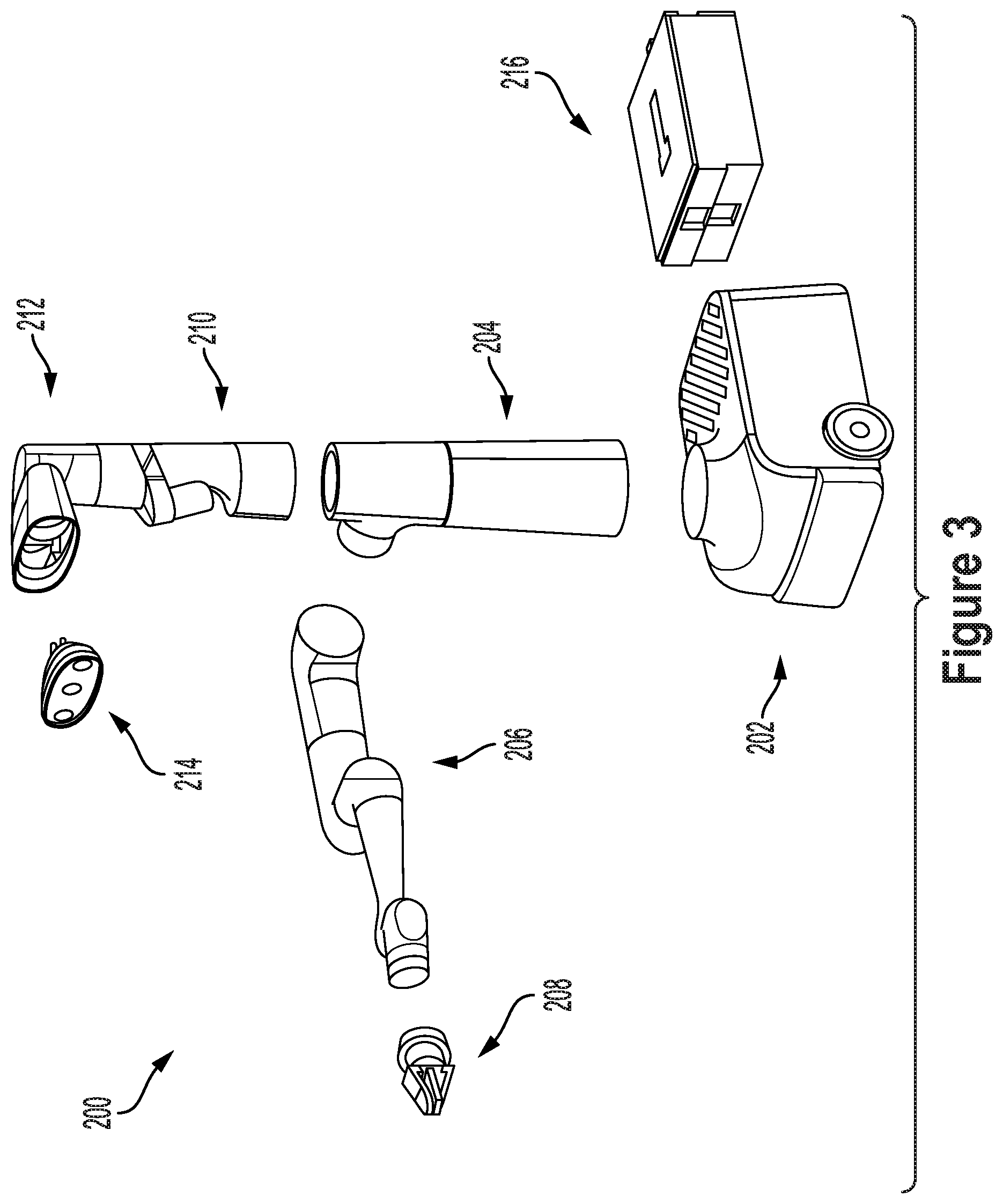
[0006] In a further embodiment, a method is provided that includes causing a shoulder yaw J0 joint of a 7DOF robotic arm of a mobile robotic device to rotate away from a first end of a mobile base to which a mounting column is fixed, where the mounting column, the shoulder yaw J0 joint of the 7DOF arm, and a perception housing of the mobile robotic device are arranged in a stacked tower such that the shoulder yaw J0 joint of the 7DOF arm is above the mounting column and below the perception housing. The method further includes causing a shoulder pitch J1 joint of the 7DOF robotic arm of the mobile robotic device to rotate vertical up. The method additionally includes causing an elbow pitch J3 joint to rotate vertical down. The method also includes causing a wrist pitch J5 joint to rotate vertical down to position the 7DOF robotic arm in a shoulder up stowed configuration.
[0007] In another embodiment, a system is provided that includes means for causing a shoulder yaw J0 joint of a 7DOF robotic arm of a mobile robotic device to rotate away from a first end of a mobile base to which a mounting column is fixed, where the mounting column, the shoulder yaw J0 joint of the 7DOF arm, and a perception housing of the mobile robotic device are arranged in a stacked tower such that the shoulder yaw J0 joint of the 7DOF arm is above the mounting column and below the perception housing. The system further includes means for causing a shoulder pitch J1 joint of the 7DOF robotic arm of the mobile robotic device to rotate vertical up. The system additionally includes means for causing an elbow pitch J3 joint to rotate vertical down. The system also includes means for causing a wrist pitch J5 joint to rotate vertical down to position the 7DOF robotic arm in a shoulder up stowed configuration.
[0008] In a further embodiment, a mobile robotic device is provided comprising a mobile base, a mounting column fixed to the mobile base, a rotatable joint that enables rotation of an appendage relative to the mounting column, and a perception housing comprising at least one sensor, wherein the mounting column, the rotatable joint, and the perception housing are arranged in a stacked tower such that the rotatable joint is above the mounting column and below the perception housing.
[0009] The foregoing summary is illustrative only and is not intended to be in any way limiting. In addition to the illustrative aspects, embodiments, and features described above, further aspects, embodiments, and features will become apparent by reference to the figures and the following detailed description and the accompanying drawings.
BRIEF DESCRIPTION OF THE DRAWINGS
[0010] FIG. 1 illustrates a configuration of a robotic system, in accordance with example embodiments.
[0011] FIG. 2 illustrates a mobile robot, in accordance with example embodiments.
[0012] FIG. 3 illustrates an exploded view of a mobile robot, in accordance with example embodiments.
[0013] FIG. 4 illustrates a robotic arm, in accordance with example embodiments.
[0014] FIG. 5 illustrates joint ranges of motion, in accordance with example embodiments.
[0015] FIGS. 6A, 6B, and 6C illustrate robot dimensions, in accordance with example embodiments.
[0016] FIGS. 7A and 7B, FIGS. 8A and 8B, and FIGS. 9A and 9B illustrate stowed configurations, in accordance with example embodiments.
[0017] FIG. 10, FIG. 11, FIG. 12, and FIG. 13 illustrate robotic arm configurations to facilitate perception of an end of arm system, in accordance with example embodiments.
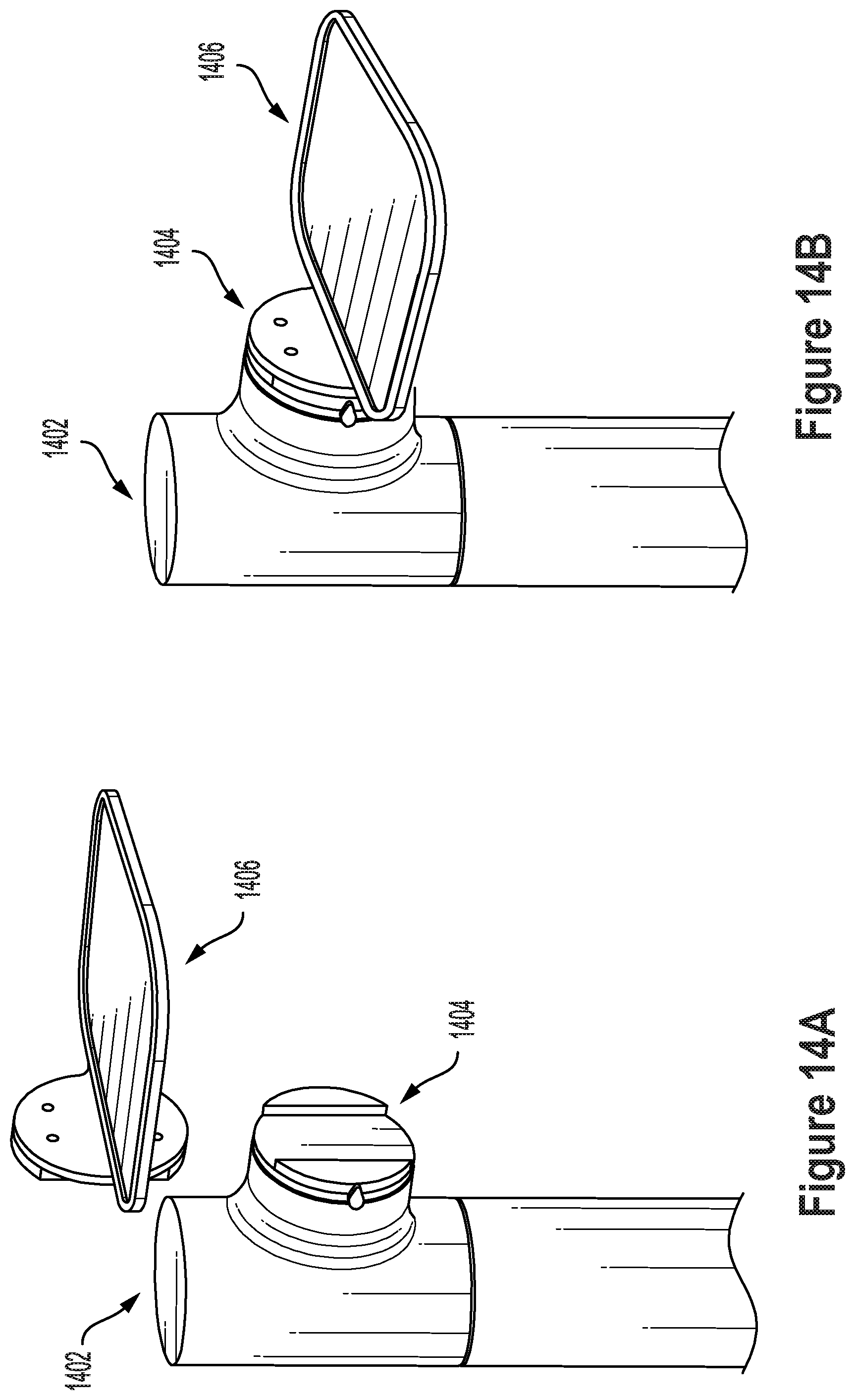
[0018] FIGS. 14A and 14B show attachment of an appendage to a rotatable joint, in accordance with example embodiments.
[0019] FIG. 15 shows positions of a rotatable joint having an attached appendage, in accordance with example embodiments.
[0020] FIG. 16 shows positions of a rotatable joint having an attached appendage, in accordance with example embodiments.
DETAILED DESCRIPTION
[0021] Example methods, devices, and systems are described herein. It should be understood that the words "example" and "exemplary" are used herein to mean "serving as an example, instance, or illustration." Any embodiment or feature described herein as being an "example" or "exemplary" is not necessarily to be construed as preferred or advantageous over other embodiments or features unless indicated as such. Other embodiments can be utilized, and other changes can be made, without departing from the scope of the subject matter presented herein.
[0022] Thus, the example embodiments described herein are not meant to be limiting. It will be readily understood that the aspects of the present disclosure, as generally described herein, and illustrated in the figures, can be arranged, substituted, combined, separated, and designed in a wide variety of different configurations.
[0023] Throughout this description, the articles "a" or "an" are used to introduce elements of the example embodiments. Any reference to "a" or "an" refers to "at least one," and any reference to "the" refers to "the at least one," unless otherwise specified, or unless the context clearly dictates otherwise. The intent of using the conjunction "or" within a described list of at least two terms is to indicate any of the listed terms or any combination of the listed terms.
[0024] The use of ordinal numbers such as "first," "second," "third" and so on is to distinguish respective elements rather than to denote a particular order of those elements. For the purpose of this description, the terms "multiple" and "a plurality of" refer to "two or more" or "more than one."
[0025] Further, unless context suggests otherwise, the features illustrated in each of the figures may be used in combination with one another. Thus, the figures should be generally viewed as component aspects of one or more overall embodiments, with the understanding that not all illustrated features are necessary for each embodiment. In the figures, similar symbols typically identify similar components, unless context dictates otherwise. Further, unless otherwise noted, figures are not drawn to scale and are used for illustrative purposes only. Moreover, the figures are representational only and not all components are shown. For example, additional structural or restraining components might not be shown.
[0026] Additionally, any enumeration of elements, blocks, or steps in this specification or the claims is for purposes of clarity. Thus, such enumeration should not be interpreted to require or imply that these elements, blocks, or steps adhere to a particular arrangement or are carried out in a particular order.
I. OVERVIEW
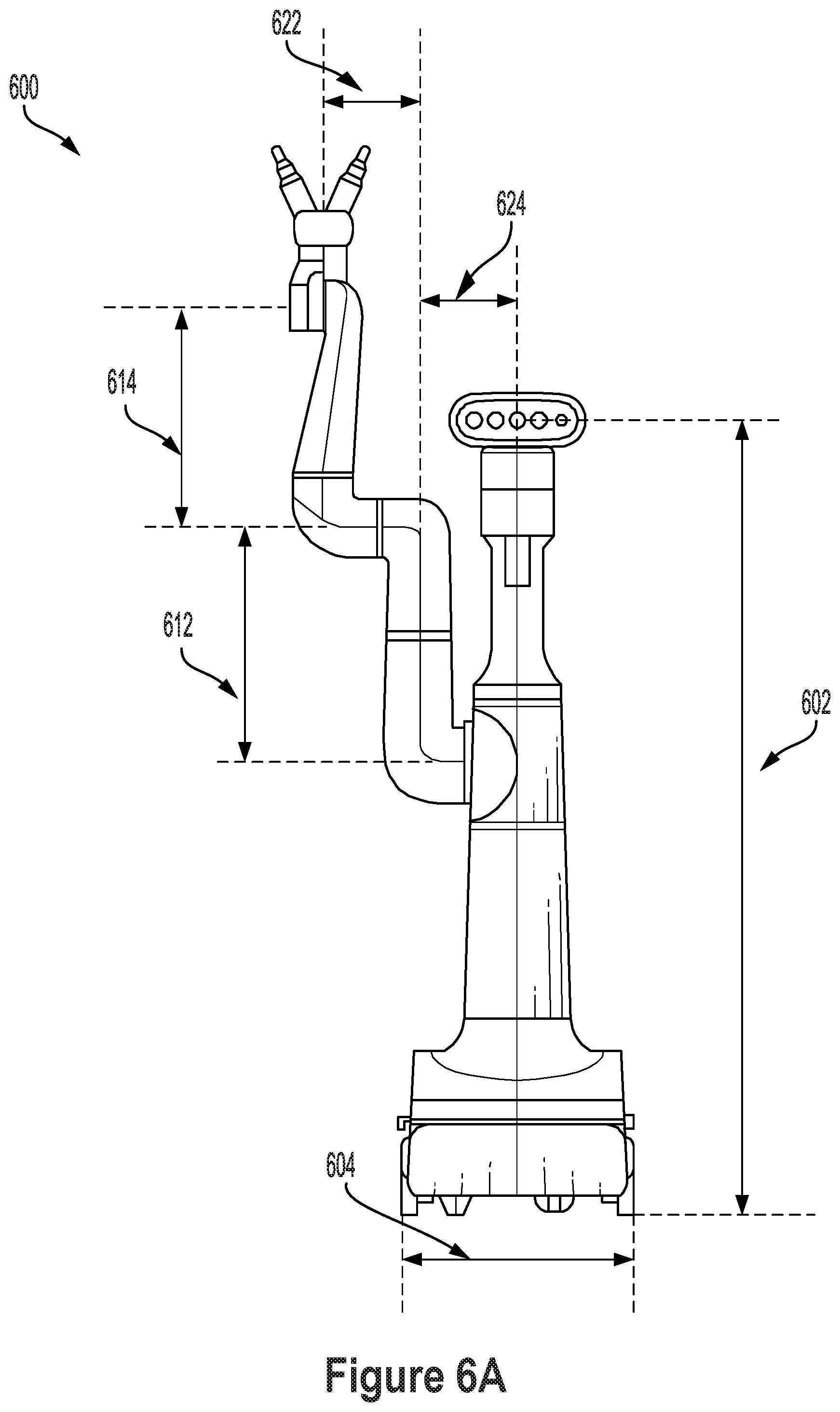
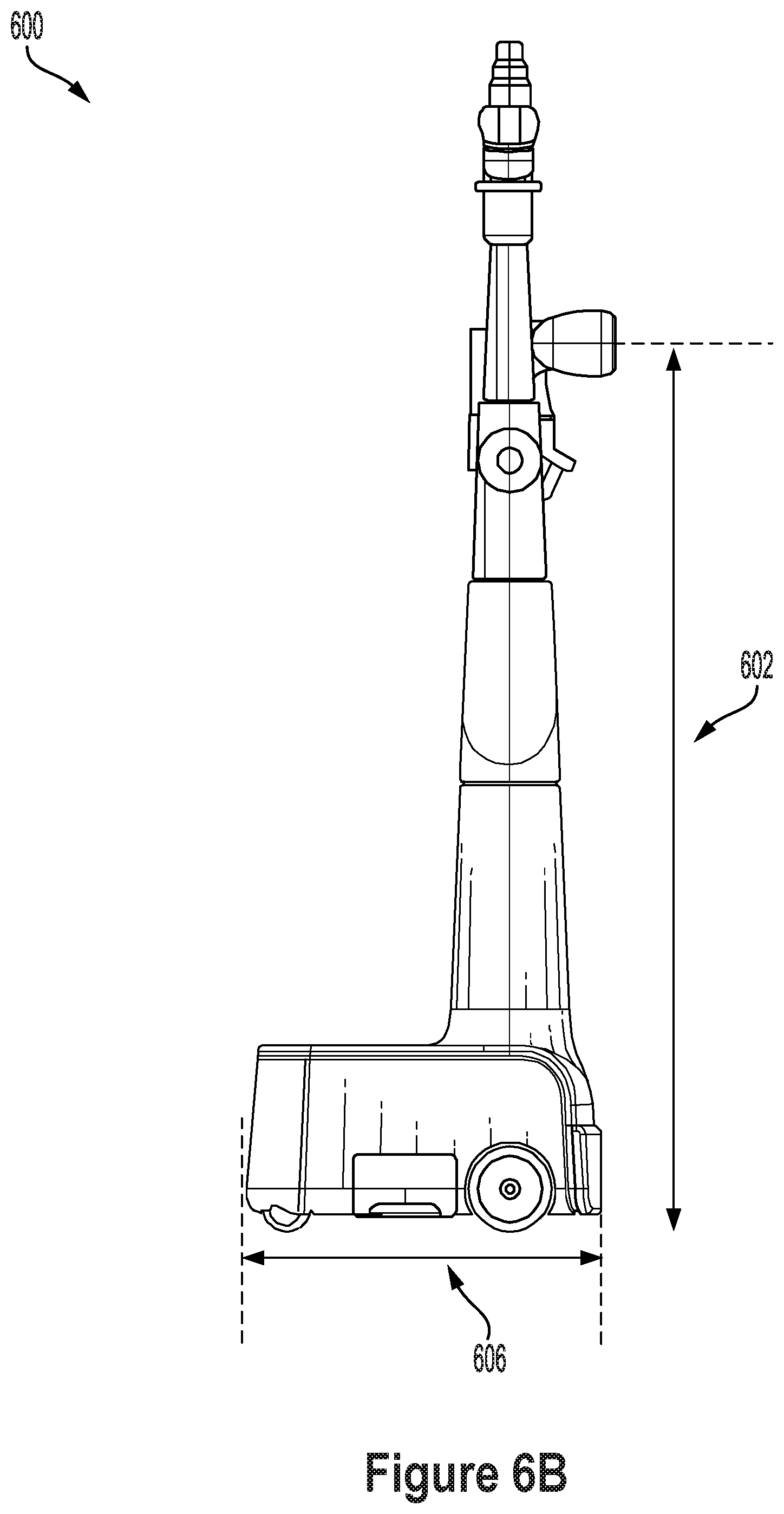
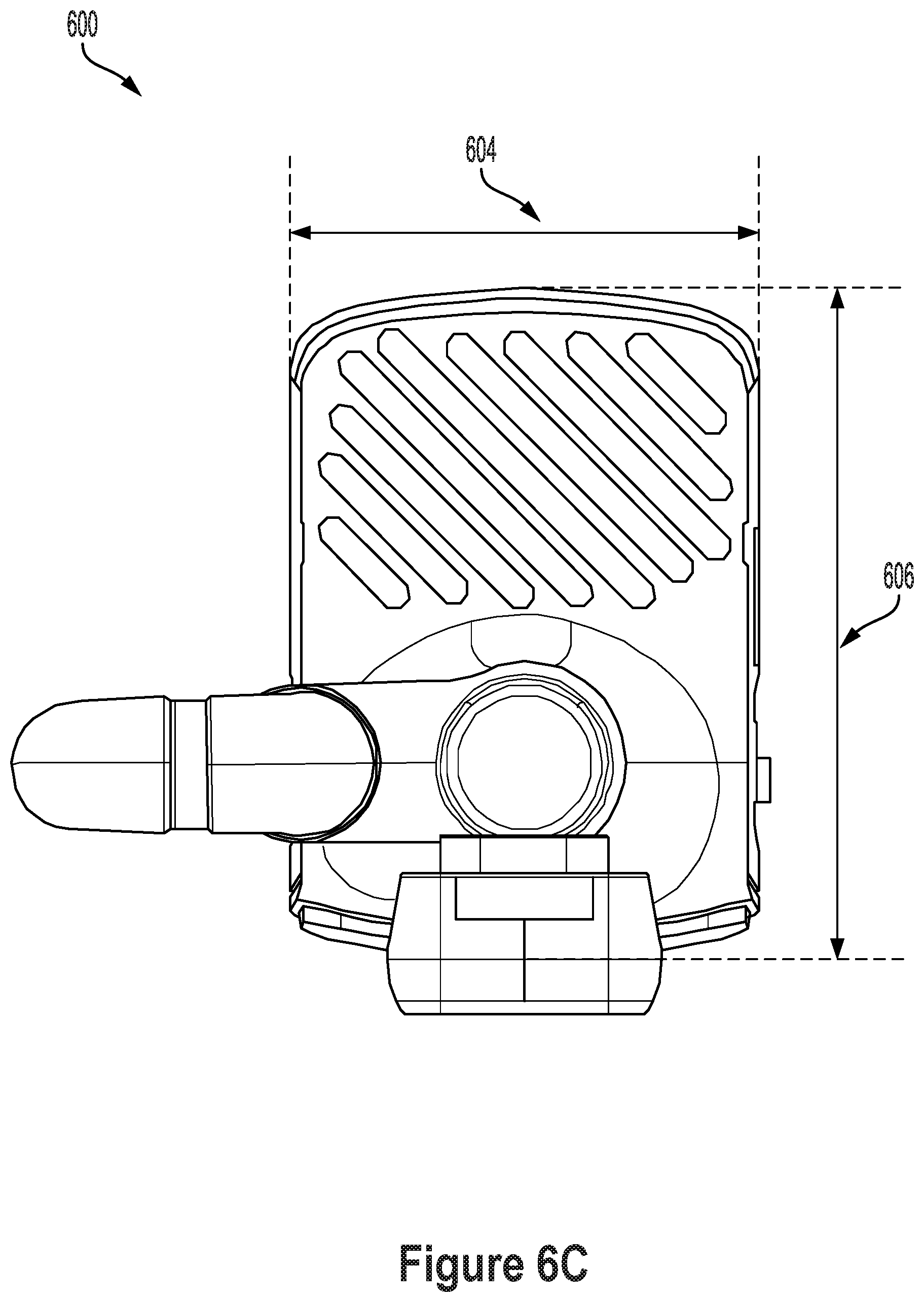
[0027] Described herein is an example robotic device along with example operations that may be performed by the example robotic device and/or variations thereof. The example robotic device may include a number of components coupled together, including a mobile base, an arm, an end of arm system (EOAS), a midsection, a mast, and a perception housing. The arm may include particular degrees of freedom (DOFs), ranges of motion (ROMs), joint types, link lengths, and joint offsets to optimize the performance of tasks. Tradeoffs exist in terms of desired operational capabilities of the robot relative to space constraints and cost constraints. Some example robots described herein are engineered to simplify manufacturing and programming, making the robots affordable for non-industrial applications.
[0028] In general, a robotic device described herein may be used in a plurality of settings and may be configured to perform operations corresponding to each setting. For example, the robotic device may be used as a household aid robot. The robotic device may be configured to collect and load laundry into a hamper or washer, clean the floor by collecting garbage, clean up toys by gathering the toys and loading them into a toy storage bin, move pieces of furniture into their proper positions, and fetch drinks, food, and keys, among other possible tasks. The robotic device may additionally be used as a yard work aid robot to perform certain yard work such as sweeping up and gathering fallen leaves, sticks, and any other undesirable items that may be left in a back or front yard. The robotic device may be configured to perform any of the operations described herein autonomously in order to reduce an amount of human input needed to control the robotic device.
[0029] An example robot includes a mobile base, such as a wheeled base. The robot additionally includes a mounting column which is fixed to the mobile base. The robot additionally includes a 7DOF robotic arm with a rotational joint that allows for rotation of the robotic arm relative to the mounting column. The robot additionally includes a perception housing with at least one sensor for perception. The mounting column, rotational joint of the arm, and the perception housing may be arranged in a stacked tower. Each component of the stacked tower may be coaxial. This arrangement may facilitate perception of an object being held or otherwise manipulated by an end effector of the robotic arm.
[0030] The stacked tower may be positioned at a front side of the mobile base over one or more drive wheels. The mobile base may additionally include a rear section behind the stacked tower. The rear section may include a flat or relatively flat top surface. The rear section may include a container for stowing objects manipulated by the robot, such as a basket or a bin. This arrangement allows the robotic arm to rotate toward the front of the robot in order to pick up an object, and then rotate toward the back of the robot to place the object on the rear section of the mobile base (e.g., on the flat surface or into a container). The same process may be repeated to efficiently perform a reverse process by moving objects currently stored on the back of the robot into the environment of the robot with the robotic arm.
[0031] Example embodiments also allow for efficient stowing of the robotic arm when the arm is not being used for manipulation. In particular, the robotic arm may be folded into a predetermined stowed configuration over the rear section of the mobile base. In some examples, the stowed configuration allows the robotic arm to be fully positioned within the footprint of the mobile base (so that no portion of the robotic arm hangs over an edge of the mobile base). To optimize space constraints, the mobile base may be designed so that the stowed configuration causes a point of the robotic arm to reach (or come within a small distance of) the rear end and/or the sides of the mobile base.
[0032] Multiple stowed configurations are possible for the example robots described herein (e.g., a shoulder up stowed configuration and a shoulder down stowed configuration). The kinematics of the robotic arm (including joint ROMs, joint offsets, and link lengths) may be chosen to facilitate transitioning the robotic arm between an active pose and a stowed configuration. In examples where multiple stowed configurations are possible, the robot may choose between stowed configurations based on which stowed configuration is easier to reach from the current active position of the robotic arm and/or based on which stowed configuration will make it easier for the robot to reach a next planned active position of the robotic arm.
[0033] After the robotic arm is folded into a stowed configuration, the robot may then navigate with the mobile base while maintaining the robotic arm fixed in the stowed configuration. The robot may later stop navigating with the mobile base and then return the robotic arm to an active position in order to manipulate an object or perform some other task in the environment.
[0034] In order to optimize overall range of motion while maintaining a compact form, the robot may be designed to be relatively tall and narrow. For instance, the height of the robot to the top of the perception housing may be more than double the length of the mobile base and more than three times the width of the mobile base. A tall, narrow stacked tower allows for a relatively long mast component between the perception housing and the rotatable joint of the 7DOF robotic arm. This arrangement facilitates perception of an end effector of the robotic arm with perception capabilities in the perception housing, whereas other robots may often end up with occlusions caused by a part of a robotic arm being between an object in a gripper and a sensor on the robot.
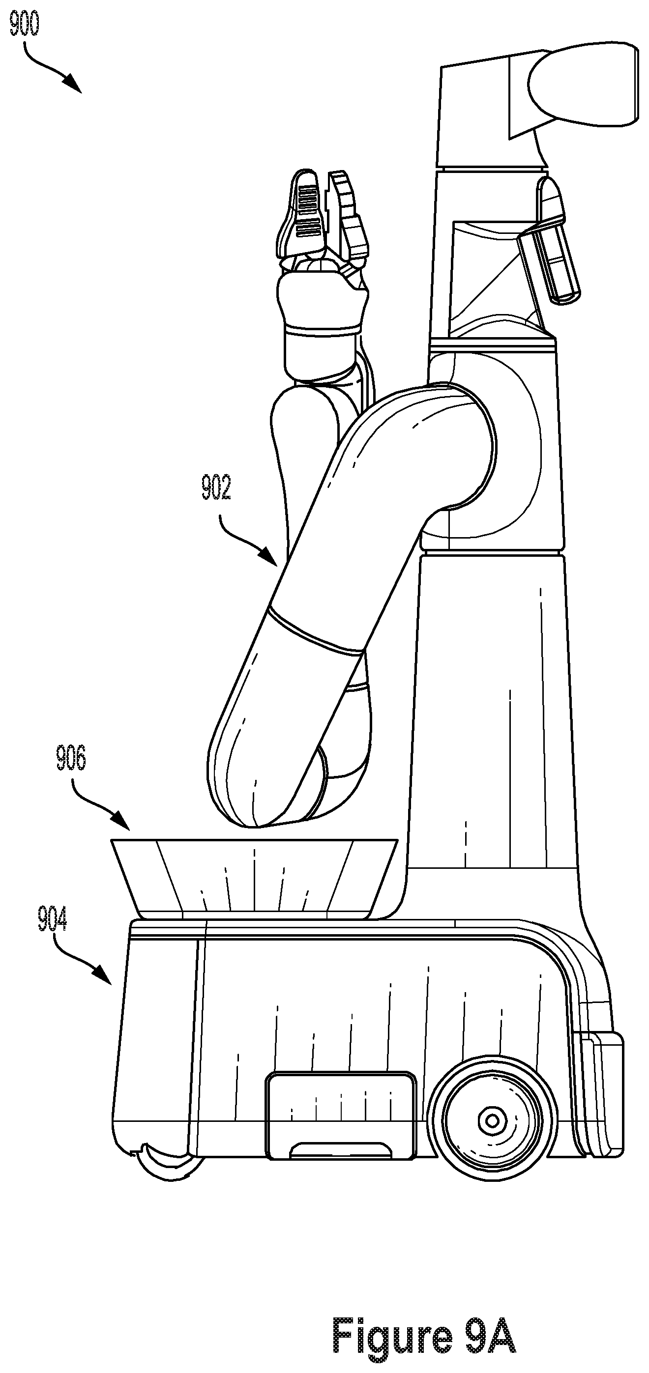
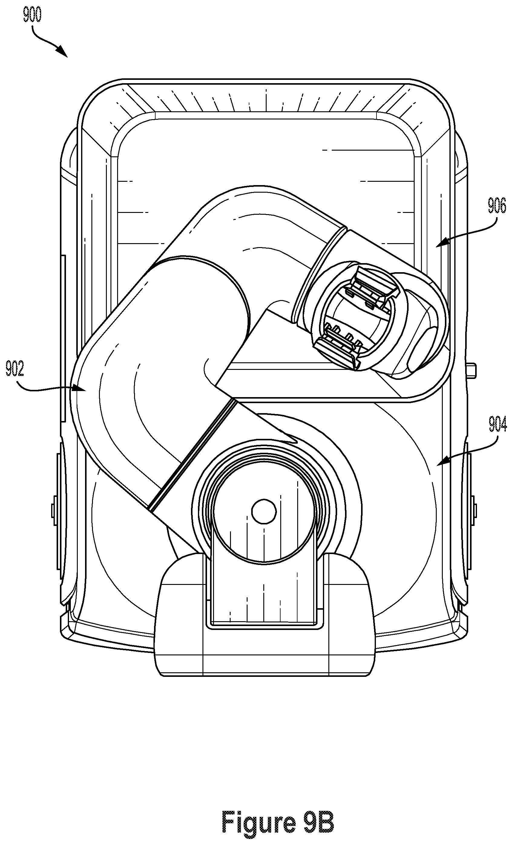
[0035] To further improve visibility between the sensors in the perception housing and the EOAS, the robotic arm may be given seven DOFs. By using seven DOFs, an extra DOF is available to choose an arm configuration that facilitates perception while placing the EOAS at a target pose in the environment. More specifically, a bicep of the robotic arm may be provided with a bicep roll joint to roll a forearm out of the way in order to improve the perception of an object being manipulated by an end effector of the robotic arm.
[0036] Link lengths and joint offsets may be chosen for the robotic arm to optimize manipulation capabilities while also facilitating efficient stowing of the robotic arm. By using joint offsets instead of intersecting axes, the upper joints of the robot may be optimized for stowing and range of motion. More specifically, a first offset between the rotational joint in the tower and a roll joint in the bicep may be set equal to or approximately equal (e.g., within 10 percent) to a second offset between the roll joint in the bicep and a roll joint in the forearm. The length of the bicep may also be set equal to or approximately equal (e.g., within 10 percent) to the length of the forearm. This arrangement advantageously allows for one offset to compensate for the other offset and/or one link length to compensate for the other link length. Using the same or approximately the same offset between these two relatively long consecutive links also improves the workspace by facilitating kinematic computations. The offsets may be set large enough (e.g., 25 millimeter gaps) to avoid pinch points that could harm a user. In alternative examples, the two offsets may be significantly different from each other and/or the two link lengths may be significantly different from each other.
II. EXAMPLE ROBOTIC SYSTEMS
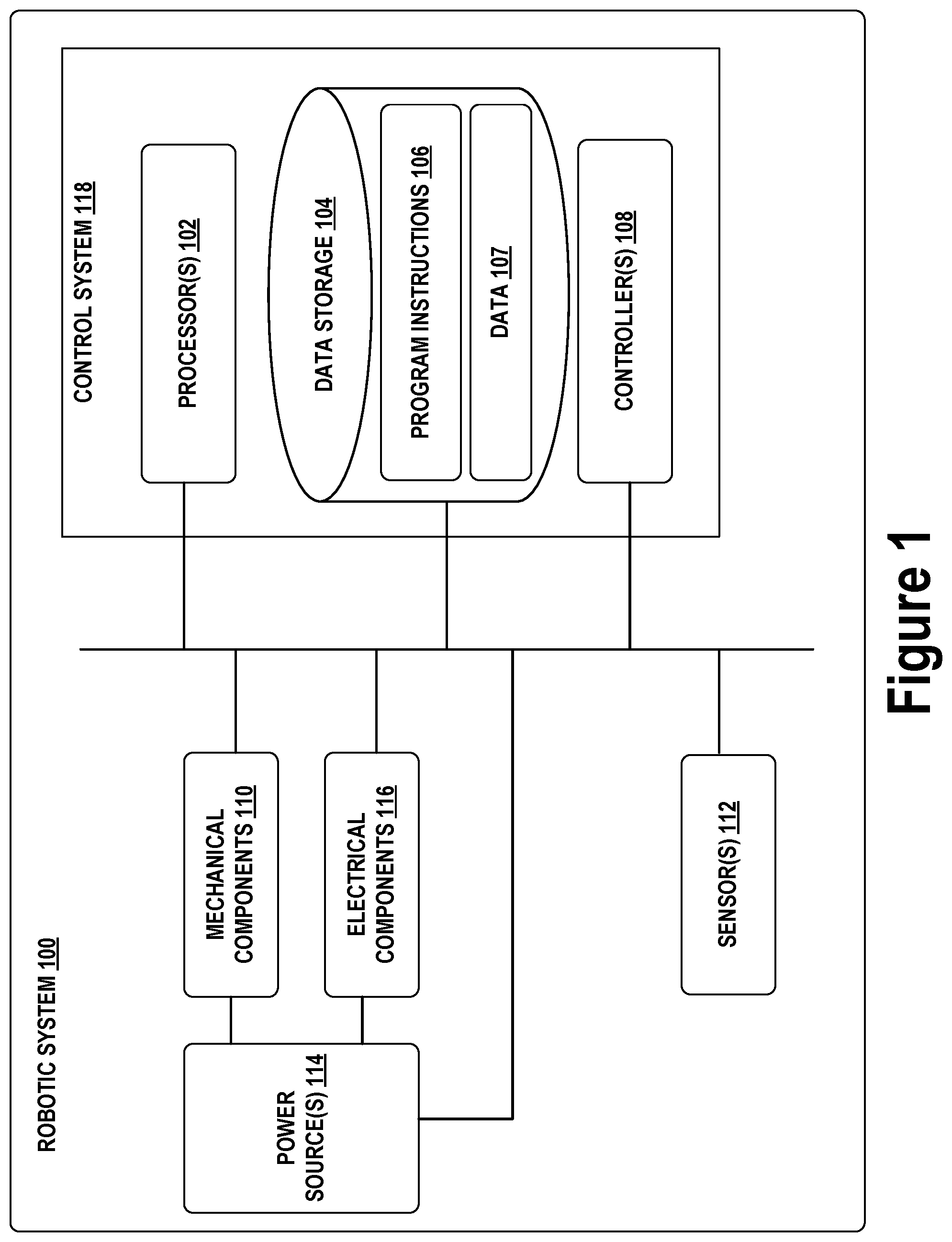
[0037] FIG. 1 illustrates an example configuration of a robotic system that may be used in connection with the implementations described herein. Robotic system 100 may be configured to operate autonomously, semi-autonomously, or using directions provided by user(s). Robotic system 100 may be implemented in various forms, such as a robotic arm, industrial robot, or some other arrangement. Some example implementations involve a robotic system 100 engineered to be low cost at scale and designed to support a variety of tasks. Robotic system 100 may be designed to be capable of operating around people. Robotic system 100 may also be optimized for machine learning. Throughout this description, robotic system 100 may also be referred to as a robot, robotic device, or mobile robot, among other designations.
[0038] As shown in FIG. 1, robotic system 100 may include processor(s) 102, data storage 104, and controller(s) 108, which together may be part of control system 118. Robotic system 100 may also include sensor(s) 112, power source(s) 114, mechanical components 110, and electrical components 116. Nonetheless, robotic system 100 is shown for illustrative purposes, and may include more or fewer components. The various components of robotic system 100 may be connected in any manner, including wired or wireless connections. Further, in some examples, components of robotic system 100 may be distributed among multiple physical entities rather than a single physical entity. Other example illustrations of robotic system 100 may exist as well.
[0039] Processor(s) 102 may operate as one or more general-purpose hardware processors or special purpose hardware processors (e.g., digital signal processors, application specific integrated circuits, etc.). Processor(s) 102 may be configured to execute computer-readable program instructions 106, and manipulate data 107, both of which are stored in data storage 104. Processor(s) 102 may also directly or indirectly interact with other components of robotic system 100, such as sensor(s) 112, power source(s) 114, mechanical components 110, or electrical components 116.
[0040] Data storage 104 may be one or more types of hardware memory. For example, data storage 104 may include or take the form of one or more computer-readable storage media that can be read or accessed by processor(s) 102. The one or more computer-readable storage media can include volatile or non-volatile storage components, such as optical, magnetic, organic, or another type of memory or storage, which can be integrated in whole or in part with processor(s) 102. In some implementations, data storage 104 can be a single physical device. In other implementations, data storage 104 can be implemented using two or more physical devices, which may communicate with one another via wired or wireless communication. As noted previously, data storage 104 may include the computer-readable program instructions 106 and data 107. Data 107 may be any type of data, such as configuration data, sensor data, or diagnostic data, among other possibilities.
[0041] Controller 108 may include one or more electrical circuits, units of digital logic, computer chips, or microprocessors that are configured to (perhaps among other tasks), interface between any combination of mechanical components 110, sensor(s) 112, power source(s) 114, electrical components 116, control system 118, or a user of robotic system 100. In some implementations, controller 108 may be a purpose-built embedded device for performing specific operations with one or more subsystems of the robotic system 100.
[0042] Control system 118 may monitor and physically change the operating conditions of robotic system 100. In doing so, control system 118 may serve as a link between portions of robotic system 100, such as between mechanical components 110 or electrical components 116. In some instances, control system 118 may serve as an interface between robotic system 100 and another computing device. Further, control system 118 may serve as an interface between robotic system 100 and a user. In some instances, control system 118 may include various components for communicating with robotic system 100, including a joystick, buttons, or ports, etc. The example interfaces and communications noted above may be implemented via a wired or wireless connection, or both. Control system 118 may perform other operations for robotic system 100 as well.
[0043] During operation, control system 118 may communicate with other systems of robotic system 100 via wired or wireless connections, and may further be configured to communicate with one or more users of the robot. As one possible illustration, control system 118 may receive an input (e.g., from a user or from another robot) indicating an instruction to perform a requested task, such as to pick up and move an object from one location to another location. Based on this input, control system 118 may perform operations to cause the robotic system 100 to make a sequence of movements to perform the requested task. As another illustration, a control system may receive an input indicating an instruction to move to a requested location. In response, control system 118 (perhaps with the assistance of other components or systems) may determine a direction and speed to move robotic system 100 through an environment en route to the requested location.
[0044] Operations of control system 118 may be carried out by processor(s) 102. Alternatively, these operations may be carried out by controller(s) 108, or a combination of processor(s) 102 and controller(s) 108. In some implementations, control system 118 may partially or wholly reside on a device other than robotic system 100, and therefore may at least in part control robotic system 100 remotely.
[0045] Mechanical components 110 represent hardware of robotic system 100 that may enable robotic system 100 to perform physical operations. As a few examples, robotic system 100 may include one or more physical members, such as an arm, an end effector, a perception housing, a mast, a midsection, a base, and wheels. The physical members or other parts of robotic system 100 may further include actuators arranged to move the physical members in relation to one another. Robotic system 100 may also include one or more structured bodies for housing control system 118 or other components, and may further include other types of mechanical components. The particular mechanical components 110 used in a given robot may vary based on the design of the robot, and may also be based on the operations or tasks the robot may be configured to perform.
[0046] In some examples, mechanical components 110 may include one or more removable components. Robotic system 100 may be configured to add or remove such removable components, which may involve assistance from a user or another robot. For example, robotic system 100 may be configured with removable end effectors or digits that can be replaced or changed as needed or desired. In some implementations, robotic system 100 may include one or more removable or replaceable battery units, control systems, power systems, bumpers, or sensors. Other types of removable components may be included within some implementations.
[0047] Robotic system 100 may include sensor(s) 112 arranged to sense aspects of robotic system 100. Sensor(s) 112 may include one or more force sensors, torque sensors, velocity sensors, acceleration sensors, position sensors, proximity sensors, motion sensors, location sensors, load sensors, temperature sensors, touch sensors, depth sensors, ultrasonic range sensors, infrared sensors, object sensors, or cameras, among other possibilities. Within some examples, robotic system 100 may be configured to receive sensor data from sensors that are physically separated from the robot (e.g., sensors that are positioned on other robots or located within the environment in which the robot is operating).
[0048] Sensor(s) 112 may provide sensor data to processor(s) 102 (perhaps by way of data 107) to allow for interaction of robotic system 100 with its environment, as well as monitoring of the operation of robotic system 100. The sensor data may be used in evaluation of various factors for activation, movement, and deactivation of mechanical components 110 and electrical components 116 by control system 118. For example, sensor(s) 112 may capture data corresponding to the terrain of the environment or location of nearby objects, which may assist with environment recognition and navigation.
[0049] In some examples, sensor(s) 112 may include RADAR (e.g., for long-range object detection, distance determination, or speed determination), LIDAR (e.g., for short-range object detection, distance determination, or speed determination), SONAR (e.g., for underwater object detection, distance determination, or speed determination), VICON.RTM. (e.g., for motion capture), one or more cameras (e.g., stereoscopic cameras for 3D vision), a global positioning system (GPS) transceiver, or other sensors for capturing information of the environment in which robotic system 100 is operating. Sensor(s) 112 may monitor the environment in real time, and detect obstacles, elements of the terrain, weather conditions, temperature, or other aspects of the environment. In another example, sensor(s) 112 may capture data corresponding to one or more characteristics of a target or identified object, such as a size, shape, profile, structure, or orientation of the object.
[0050] Further, robotic system 100 may include sensor(s) 112 configured to receive information indicative of the state of robotic system 100, including sensor(s) 112 that may monitor the state of the various components of robotic system 100. Sensor(s) 112 may measure activity of systems of robotic system 100 and receive information based on the operation of the various features of robotic system 100, such as the operation of an extendable arm, an end effector, other mechanical or electrical features of robotic system 100. The data provided by sensor(s) 112 may enable control system 118 to determine errors in operation as well as monitor overall operation of components of robotic system 100.
[0051] As an example, robotic system 100 may use force/torque sensors to measure load on various components of robotic system 100. In some implementations, robotic system 100 may include one or more force/torque sensors on an arm or end effector to measure the load on the actuators that move one or more members of the arm or end effector. In some examples, the robotic system 100 may include a force/torque sensor at or near the wrist or end effector, but not at or near other joints of a robotic arm. In further examples, robotic system 100 may use one or more position sensors to sense the position of the actuators of the robotic system. For instance, such position sensors may sense states of extension, retraction, positioning, or rotation of the actuators on an arm or end effector.
[0052] As another example, sensor(s) 112 may include one or more velocity or acceleration sensors. For instance, sensor(s) 112 may include an inertial measurement unit (IMU). The IMU may sense velocity and acceleration in the world frame, with respect to the gravity vector. The velocity and acceleration sensed by the IMU may then be translated to that of robotic system 100 based on the location of the IMU in robotic system 100 and the kinematics of robotic system 100.
[0053] Robotic system 100 may include other types of sensors not explicitly discussed herein. Additionally or alternatively, the robotic system may use particular sensors for purposes not enumerated herein.
[0054] Robotic system 100 may also include one or more power source(s) 114 configured to supply power to various components of robotic system 100. Among other possible power systems, robotic system 100 may include a hydraulic system, electrical system, batteries, or other types of power systems. As an example illustration, robotic system 100 may include one or more batteries configured to provide charge to components of robotic system 100. Some of mechanical components 110 or electrical components 116 may each connect to a different power source, may be powered by the same power source, or be powered by multiple power sources.
[0055] Any type of power source may be used to power robotic system 100, such as electrical power or a gasoline engine. Additionally or alternatively, robotic system 100 may include a hydraulic system configured to provide power to mechanical components 110 using fluid power. Components of robotic system 100 may operate based on hydraulic fluid being transmitted throughout the hydraulic system to various hydraulic motors and hydraulic cylinders, for example. The hydraulic system may transfer hydraulic power by way of pressurized hydraulic fluid through tubes, flexible hoses, or other links between components of robotic system 100. Power source(s) 114 may charge using various types of charging, such as wired connections to an outside power source, wireless charging, combustion, or other examples.
[0056] Electrical components 116 may include various mechanisms capable of processing, transferring, or providing electrical charge or electric signals. Among possible examples, electrical components 116 may include electrical wires, circuitry, or wireless communication transmitters and receivers to enable operations of robotic system 100. Electrical components 116 may interwork with mechanical components 110 to enable robotic system 100 to perform various operations. Electrical components 116 may be configured to provide power from power source(s) 114 to the various mechanical components 110, for example. Further, robotic system 100 may include electric motors. Other examples of electrical components 116 may exist as well.
[0057] Robotic system 100 may include a body, which may connect to or house appendages and components of the robotic system. As such, the structure of the body may vary within examples and may further depend on particular operations that a given robot may have been designed to perform. For example, a robot developed to carry heavy loads may have a wide body that enables placement of the load. Similarly, a robot designed to operate in tight spaces may have a relatively tall, narrow body. Further, the body or the other components may be developed using various types of materials, such as metals or plastics. Within other examples, a robot may have a body with a different structure or made of various types of materials.
[0058] The body or the other components may include or carry sensor(s) 112. These sensors may be positioned in various locations on the robotic system 100, such as on a body, a perception housing, or an end effector, among other examples.
[0059] Robotic system 100 may be configured to carry a load, such as a type of cargo that is to be transported. In some examples, the load may be placed by the robotic system 100 into a bin or other container attached to the robotic system 100. The load may also represent external batteries or other types of power sources (e.g., solar panels) that the robotic system 100 may utilize. Carrying the load represents one example use for which the robotic system 100 may be configured, but the robotic system 100 may be configured to perform other operations as well.
[0060] As noted above, robotic system 100 may include various types of appendages, wheels, end effectors, gripping devices and so on. In some examples, robotic system 100 may include a mobile base with wheels, treads, or some other form of locomotion. Additionally, robotic system 100 may include a robotic arm or some other form of robotic manipulator. In the case of a mobile base, the base may be considered as one of mechanical components 110 and may include wheels, powered by one or more of actuators, which allow for mobility of a robotic arm in addition to the rest of the body.
[0061] FIG. 2 illustrates a mobile robot, in accordance with example embodiments. FIG. 3 illustrates an exploded view of the mobile robot, in accordance with example embodiments. More specifically, a robot 200 may include a mobile base 202, a midsection 204, an arm 206, an end-of-arm system (EOAS) 208, a mast 210, a perception housing 212, and a perception suite 214. The robot 200 may also include a compute box 216 stored within mobile base 202.
[0062] The mobile base 202 includes two drive wheels positioned at a front end of the robot 200 in order to provide locomotion to robot 200. The mobile base 202 also includes additional casters (not shown) to facilitate motion of the mobile base 202 over a ground surface. The mobile base 202 may have a modular architecture that allows compute box 216 to be easily removed. Compute box 216 may serve as a removable control system for robot 200 (rather than a mechanically integrated control system). After removing external shells, the compute box 216 can be easily removed, tested, debugged, and/or replaced. Modularity within compute box 216 may additionally allow the control and perception systems to be independently upgraded. Physical modules inside compute box 216 may also be arranged to minimize cables. The boards inside may interlock in a structure to expose connectors where they are needed externally instead of running cables internal to the compute box 216. The mobile base 202 may also be designed to allow for additional modularity. For example, the mobile base 202 may also be designed so that a power system, a battery, and/or external bumpers can all be easily removed and/or replaced.
[0063] The midsection 204 may be attached to the mobile base 202 at a front end of the mobile base 202. The midsection 204 includes a mounting column which is fixed to the mobile base 202. The midsection 204 additionally includes a rotational joint for arm 206. More specifically, the midsection 204 includes the first two degrees of freedom for arm 206 (a shoulder yaw J0 joint and a shoulder pitch J1 joint). The mounting column and the shoulder yaw J0 joint may form a portion of a stacked tower at the front of mobile base 202. The mounting column and the shoulder yaw J0 joint may be coaxial. The length of the mounting column of midsection 204 may be chosen to provide the arm 206 with sufficient height to perform manipulation tasks at commonly encountered height levels (e.g., coffee table top and countertop levels). The length of the mounting column of midsection 204 may also allow the shoulder pitch J1 joint to rotate the arm 206 over the mobile base 202 without contacting the mobile base 202.
[0064] The arm 206 may be a 7DOF robotic arm when connected to the midsection 204. As noted, the first two DOFs of the arm 206 may be included in the midsection 204. The remaining five DOFs may be included in a standalone section of the arm 206 as illustrated in FIGS. 2 and 3. The arm 206 may be made up of plastic monolithic link structures. Inside the arm 206 may be housed standalone actuator modules, local motor drivers, and thru bore cabling. Exemplary joint types, ROMs, link lengths, and joint offsets of the arm 206 are described in more detail below.
[0065] The EOAS 208 may be an end effector at the end of arm 206. EOAS 208 may allow the robot 200 to manipulate objects in the environment. As shown in FIGS. 2 and 3, EOAS 208 may be a gripper, such as an underactuated pinch gripper. The gripper may include one or more contact sensors such as force/torque sensors and/or non-contact sensors such as one or more cameras to facilitate object detection and gripper control. EOAS 208 may also be a different type of gripper such as a suction gripper or a different type of tool such as a drill or a brush. EOAS 208 may also be swappable or include swappable components such as gripper digits.
[0066] The mast 210 may be a relatively long, narrow component between the shoulder yaw J0 joint for arm 206 and perception housing 212. The mast 210 may be part of the stacked tower at the front of mobile base 202. The mast 210 may be fixed relative to the mobile base 202. The mast 210 may be coaxial with the midsection 204. The length of the mast 210 may facilitate perception by perception suite 214 of objects being manipulated by EOAS 208. The mast 210 may have a length such that when the shoulder pitch J1 joint is rotated vertical up, a topmost point of a bicep of the arm 206 is approximately aligned with a top of the mast 210. The length of the mast 210 may then be sufficient to prevent a collision between the perception housing 212 and the arm 206 when the shoulder pitch J1 joint is rotated vertical up.
[0067] As shown in FIGS. 2 and 3, the mast 210 may include a 3D lidar sensor configured to collect depth information about the environment. The 3D lidar sensor may be coupled to a carved out portion of the mast 210 and fixed at a downward angle. The lidar position may be optimized for localization, navigation, and for front cliff detection.
[0068] The perception housing 212 may include at least one sensor making up perception suite 214. The perception housing 212 may be connected to a pan/tilt control to allow for reorienting of the perception housing 212 (e.g., to view objects being manipulated by EOAS 208). The perception housing 212 may be a part of the stacked tower fixed to the mobile base 202. A rear portion of the perception housing 212 may be coaxial with the mast 210.
[0069] The perception suite 214 may include a suite of sensors configured to collect sensor data representative of the environment of the robot 200. The perception suite 214 may include an infrared (IR)-assisted stereo depth sensor. The perception suite 214 may additionally include a wide-angled red-green-blue (RGB) camera for human-robot interaction and context information. The perception suite 214 may additionally include a high resolution RGB camera for object classification. A face light ring surrounding the perception suite 214 may also be included for improved human-robot interaction and scene illumination.
[0070] FIG. 4 illustrates a robotic arm, in accordance with example embodiments. The robotic arm includes 7 DOFs: a shoulder yaw J0 joint, a shoulder pitch J1 joint, a bicep roll J2 joint, an elbow pitch J3 joint, a forearm roll J4 joint, a wrist pitch J5 joint, and wrist roll J6 joint. Each of the joints may be coupled to one or more actuators. The actuators coupled to the joints may be operable to cause movement of links down the kinematic chain (as well as any end effector attached to the robot arm).
[0071] The shoulder yaw J0 joint allows the robot arm to rotate toward the front and toward the back of the robot. One beneficial use of this motion is to allow the robot to pick up an object in front of the robot and quickly place the object on the rear section of the robot (as well as the reverse motion). Another beneficial use of this motion is to quickly move the robot arm from a stowed configuration behind the robot to an active position in front of the robot (as well as the reverse motion).
[0072] The shoulder pitch J1 joint allows the robot to lift the robot arm (e.g., so that the bicep is up to perception suite level on the robot) and to lower the robot arm (e.g., so that the bicep is just above the mobile base). This motion is beneficial to allow the robot to efficiently perform manipulation operations (e.g., top grasps and side grasps) at different target height levels in the environment. For instance, the shoulder pitch J1 joint may be rotated to a vertical up position to allow the robot to easily manipulate objects on a table in the environment. The shoulder pitch J1 joint may be rotated to a vertical down position to allow the robot to easily manipulate objects on a ground surface in the environment.
[0073] The bicep roll J2 joint allows the robot to rotate the bicep to move the elbow and forearm relative to the bicep. This motion may be particularly beneficial for facilitating a clear view of the EOAS by the robot's perception suite. By rotating the bicep roll J2 joint, the robot may kick out the elbow and forearm to improve line of sight to an object held in a gripper of the robot.
[0074] Moving down the kinematic chain, alternating pitch and roll joints (a shoulder pitch J1 joint, a bicep roll J2 joint, an elbow pitch J3 joint, a forearm roll J4 joint, a wrist pitch J5 joint, and wrist roll J6 joint) are provided to improve the manipulability of the robotic arm. The axes of the wrist pitch J5 joint, the wrist roll J6 joint, and the forearm roll J4 joint are intersecting for reduced arm motion to reorient objects. The wrist roll J6 point is provided instead of two pitch joints in the wrist in order to improve object rotation.
[0075] In some examples, a robotic arm such as the one illustrated in FIG. 4 may be capable of operating in a teach mode. In particular, teach mode may be an operating mode of the robotic arm that allows a user to physically interact with and guide robotic arm towards carrying out and recording various movements. In a teaching mode, an external force is applied (e.g., by the user) to the robotic arm based on a teaching input that is intended to teach the robot regarding how to carry out a specific task. The robotic arm may thus obtain data regarding how to carry out the specific task based on instructions and guidance from the user. Such data may relate to a plurality of configurations of mechanical components, joint position data, velocity data, acceleration data, torque data, force data, and power data, among other possibilities.
[0076] During teach mode the user may grasp onto the EOAS or wrist in some examples or onto any part of the robotic arm in other examples and provide an external force by physically moving the robotic arm. In particular, the user may guide the robotic arm towards grasping onto an object and then moving the object from a first location to a second location. As the user guides the robotic arm during teach mode, the robot may obtain and record data related to the movement such that the robotic arm may be configured to independently carry out the task at a future time during independent operation (e.g., when the robotic arm operates independently outside of teach mode). In some examples, external forces may also be applied by other entities in the physical workspace such as by other objects, machines, or robotic systems, among other possibilities.
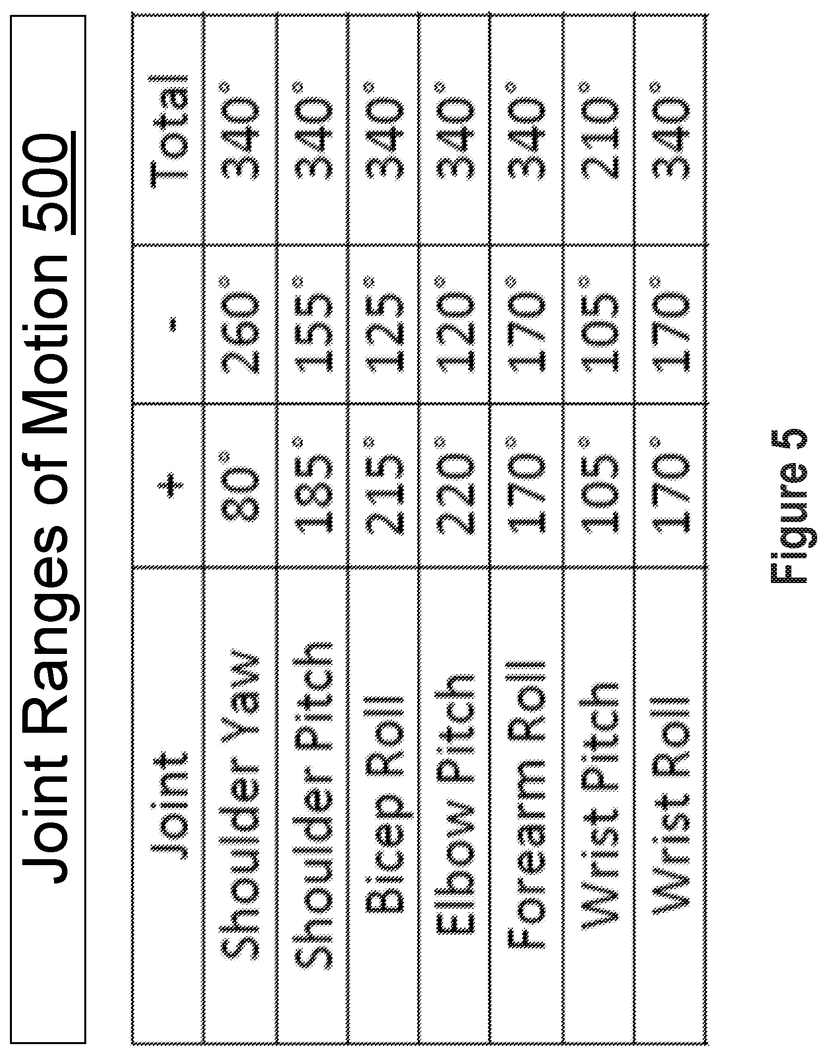
[0077] FIG. 5 is a table that illustrates joint ranges of motion 500, in accordance with example embodiments. In some examples, the joint ROMs may be chosen to optimize a right-handed elbow-up position in which the shoulder yaw J0 joint is rotated toward and perpendicular to the right side of the mobile base, the shoulder pitch J1 joint is rotated vertical up, the elbow pitch J3 joint is rotated vertical up, and the wrist pitch J5 joint is rotated vertical up. Alternative ranges of motions for any or all of the joints may also be used in other examples.
[0078] The shoulder yaw J0 joint has an asymmetric ROM that allows the shoulder yaw J0 joint to rotate 80 degrees forward and 260 degrees backward from the right-handed position. This rotatable joint enables rotation of the 7DOF robotic arm relative to the mounting column with a ROM that excludes an angle directly in front of the mobile robotic device. This ROM allows the robot to easily rotate the arm from behind the robot (e.g., from a stowed configuration) to either the left or right side of the front of the robot.
[0079] The shoulder pitch J1 joint has an asymmetric ROM that allows the shoulder pitch J1 joint to rotate 185 degrees forward and 155 degrees backward from the vertical up position. This ROM excludes a downward and back angle, and allows for stowing from the back.
[0080] The bicep roll J2 joint has an asymmetric ROM that allows the bicep roll J2 joint to rotate 215 degrees forward and 125 degrees backward from a position in which the forearm is rotated directly opposite the shoulder yaw J0 joint. This ROM allows for moving the elbow and forearm out of the way when viewing the EOAS with a perception system in the perception housing.
[0081] The elbow pitch J3 joint has an asymmetric ROM that allows the elbow pitch J3 joint to rotate 120 degrees forward and 220 degrees backward from the elbow-up position. This ROM excludes a downward and back angle, and allows for unstowing from the outside.
[0082] The forearm roll J4 joint has a symmetric ROM that allows the forearm roll J4 joint to rotate 170 degrees in either direction. This ROM provides a centered wrist pitch.
[0083] The wrist pitch J5 joint has a symmetric ROM that allows the wrist pitch J5 point to rotate 105 degrees in either direction from the vertical up position.
[0084] The wrist roll J6 joint has a symmetric ROM that allows the wrist roll J6 joint to rotate 170 degrees in either direction. This ROM is centered for a horizontal grasp.
[0085] FIGS. 6A, 6B, and 6C illustrate robot dimensions, in accordance with example embodiments. More specifically, FIG. 6A shows a front view, FIG. 6B shows a side view, and FIG. 6C shows a top down view of a robot 600. As illustrated, a relatively tall and narrow form factor may be used to optimize range of motion while minimizing space utilization.
[0086] In some examples, the height 602 of the robot 600 is more than double the length 606 of the mobile base of the robot 600. In further examples, the height 602 of the robot 600 is more than triple the width 604 of the mobile base of the robot 600. For instance, in one example implementation, the height 602 is 1351 mm, the length 606 is 535.6 mm, and the width 604 is 396.3 mm. The midsection of the robot 600 may be made long enough to allow the shoulder to rotate vertical down without colliding with the mobile base. Furthermore, the mast of the robot 600 may be long enough to allow the shoulder to rotate vertical up without colliding with the perception housing. A relatively long mast may facilitate perception of the EOAS without having occlusions caused by the robot arm.
[0087] In the arm, the length 612 of the bicep of the robot 600 may be approximately the same length as the length 614 of the forearm of the robot 600. More specifically, in some examples, the length 614 of the forearm may be within 10% of the length 612 of the bicep. For instance, the length 612 of the bicep may be 400 mm and the length 614 of the forearm may be 365 mm. The approximately matching lengths allow the bicep and forearm to compensate for each other when rotated opposite each (e.g., in the shoulder-down, elbow-up position).
[0088] In further examples, the offset 624 between the shoulder yaw J0 joint and the bicep roll J2 joint may set equal to or approximately equal to the offset 622 between the bicep roll J2 joint and the forearm roll J4 joint. For instance, the offset 622 and the offset 624 may both be set to 165 mm. In further examples, the offset 624 may be within 10% of the offset 622. The matching or approximately matching offsets may allow for easy stowing and simplified kinematics.
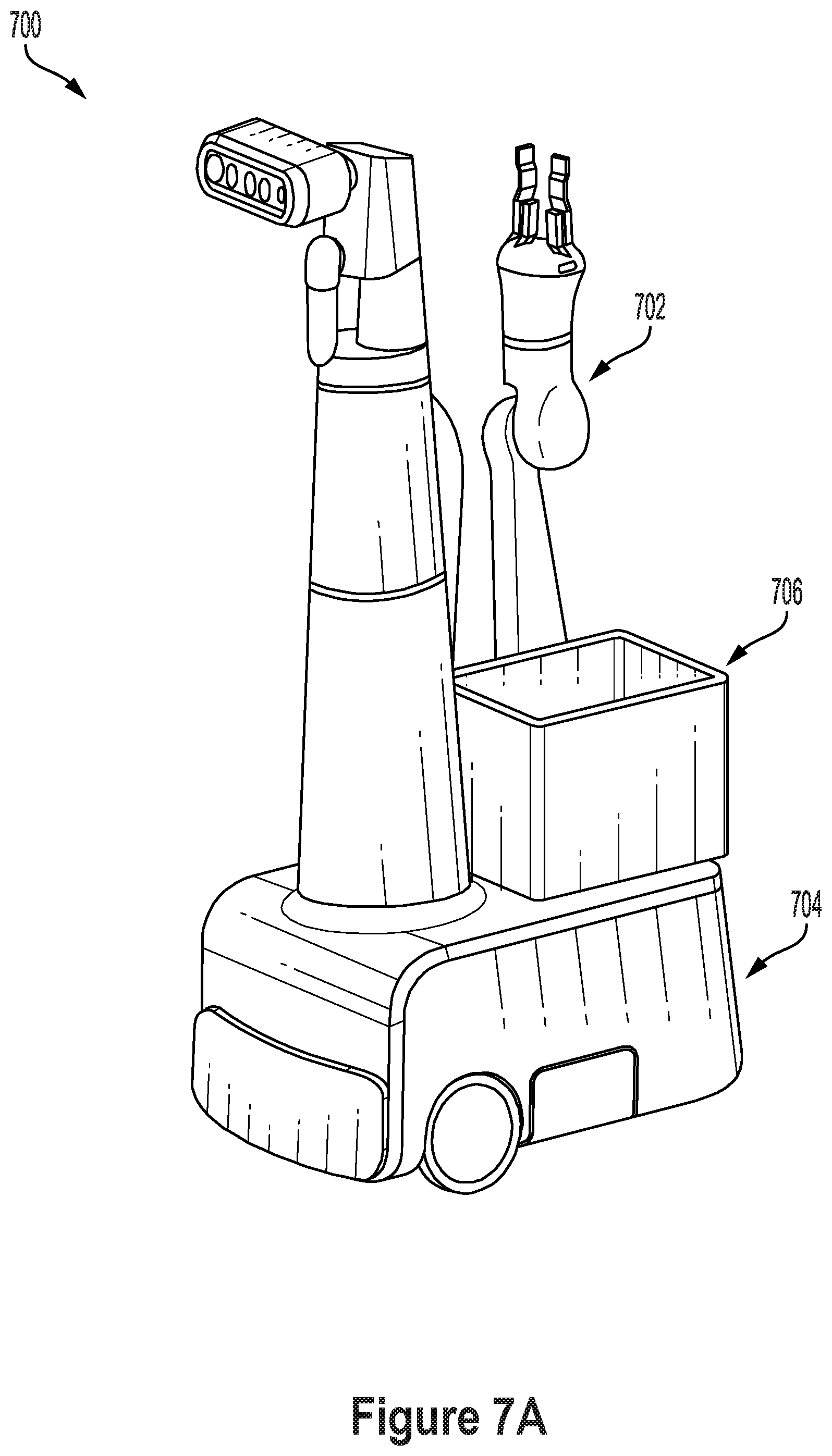
[0089] FIGS. 7A and 7B, FIGS. 8A and 8B, and FIGS. 9A and 9B illustrate stowed configurations into which some example robots described herein are capable of folding. In some examples, a robot may only be configured to fold into a single stowed configuration (e.g., the configuration shown in FIGS. 7A and 7B, the configuration shown in FIGS. 8A and 8B, or the configuration shown in FIGS. 9A and 9B). In other examples, a robot may be capable of folding into multiple stowed configurations (e.g., the configuration shown in each of FIGS. 7A and 7B, FIGS. 8A and 8B, and FIGS. 9A and 9B). The robot may then be programmed to choose between stowed configurations based on various factors, including a current active position of the robot arm before folding into the stowed configuration or a planned future active position of the robot arm after folding into the stowed configuration.
[0090] FIGS. 7A and 7B show perspective and top-down views of a robot 700 in a shoulder-down, elbow-up stowed configuration, in accordance with example embodiments. This configuration of the arm 702 may involve the shoulder pitch J1 joint being rotated vertical down and the elbow pitch J3 joint being rotated vertical up. The configuration may also involve the wrist pitch J5 point being rotated vertical up. The configuration may also involve the shoulder yaw J0 joint being rotated toward the rear section of the mobile base 704 of the robot 700. In the example illustrated, the robot 700 has a container 706 on the rear section of the robot 700. The shoulder yaw J0 joint may be angled as shown so that the robot arm 702 may fit within a remaining portion of the rear section of the robot. In this stowed configuration, the robot arm 702 may fit within the footprint of the mobile base 704 when viewed from above.
[0091] In an alternative variation of the shoulder-down, elbow-up stowed configuration, the shoulder yaw J0 joint may be rotated directly opposite the front of the mobile robot. This configuration may be used for a robot which does not have a container on the rear section of the mobile base. In this configuration, the robot arm may extend all the way to the rear end of the mobile base, or approximately to the end of the mobile base. The configuration may minimize space utilization while also facilitating transition of the robot art from the stowed configuration to an active position.
[0092] FIGS. 8A and 8B show perspective and top-down views of a robot 800 in a shoulder-up, elbow-down stowed configuration, in accordance with example embodiments. This configuration of the arm 802 may be considered a mirror position of the shoulder-down, elbow-up position with the shoulder yaw J0 joint rotated directly opposite the front of the mobile robot, as described in the preceding paragraph. The shoulder-up, elbow-down configuration may involve the shoulder pitch J1 joint being rotated vertical up and the elbow pitch J3 joint being rotated vertical down. The configuration may also involve the wrist pitch J5 point being rotated vertical down. In the example illustrated, the robot has a container 806 on the rear section of the robot 800. The robot arm 802 may be positioned so that the robot arm 802 is vertically above the container 806. In this stowed configuration, the robot arm 802 may fit within the footprint of the mobile base 804 when viewed from above.
[0093] FIGS. 9A and 9B show perspective and top-down views of another stowed configuration for a robot 900 in which the robot arm 902 is folded within the footprint of the mobile base 904 when viewed from above. In this configuration, the shoulder and the elbow are angled so that the robot arm 902 is above container 906 and approaches both sides of the mobile base 904. The robot 900 may also be capable of folding into a mirrored stowed configuration in which the positions of the bicep and forearm are reversed.
[0094] Other stowed configurations are also possible. By stowing the robot arm within a stowed configuration that keeps the robot arm contained or nearly contained within the footprint of the mobile base, robot navigation with the mobile base may be facilitated. The robot arm kinematics, including the rotational J0 joint, may facilitate transitioning to and from a stowed configuration.
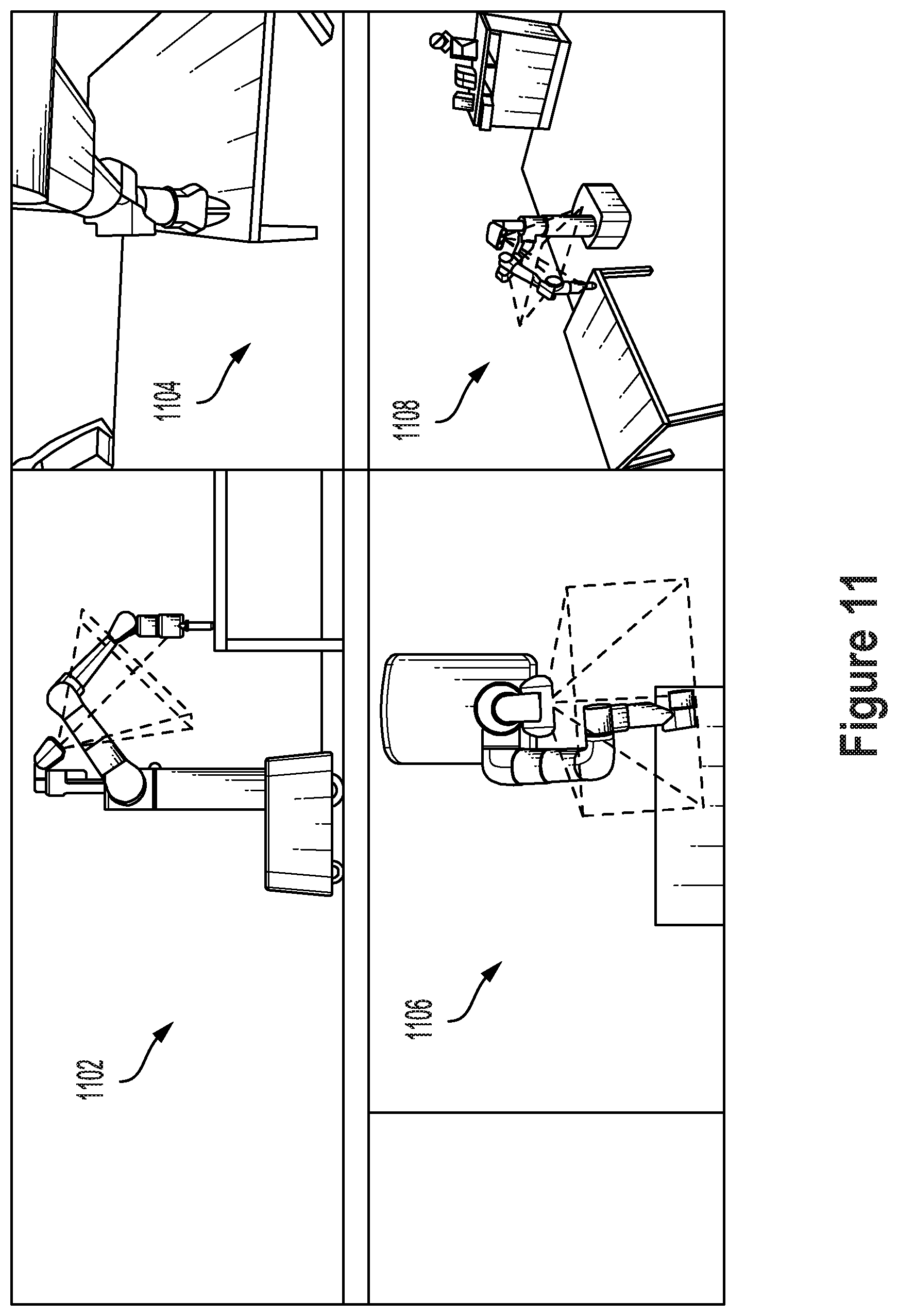
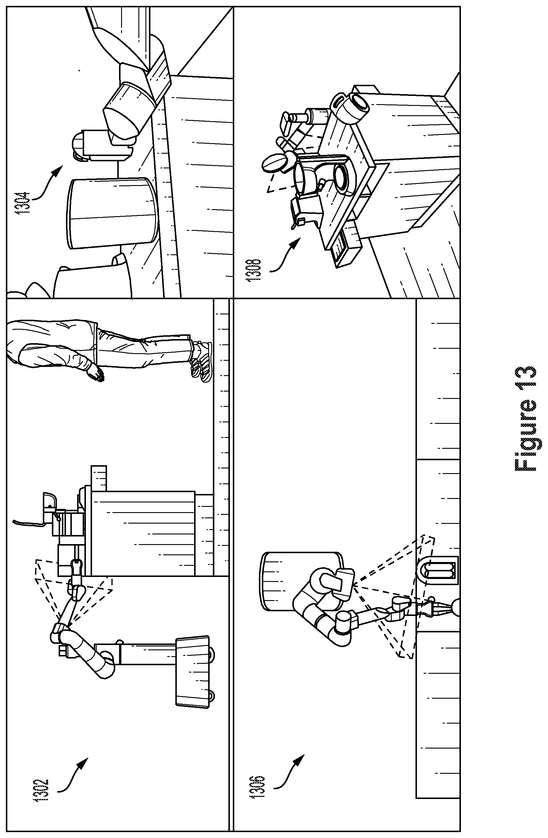
[0095] FIG. 10, FIG. 11, FIG. 12, and FIG. 13 illustrate robotic arm configurations to facilitate perception of an EOAS, in accordance with example embodiments. The robotic arm morphology, kinematics, link lengths, and ROMs may be optimized to enable a line of sight between the perception system in the perception housing and the EOAS when the EOAS is positioned at target work heights, such as proximate to a ground floor, at a height of the mounting column (e.g., coffee table level), and when the end effector is at a height of the perception housing (e.g., kitchen counter level). The robotic arm may also be optimized for certain types of grasps, such as a top grasp and a side grasp.
[0096] FIG. 10 illustrates views 1002, 1004, 1006, and 1008 of a top grasp at floor level in which the forearm is vertical or nearly vertical. FIG. 11 illustrates views 1102, 1104, 1106, and 1108 of a top grasp at coffee table level in which the forearm is vertical or nearly vertical. FIG. 12 illustrates views 1202, 1204, 1206, and 1208 of a side grasp at coffee table level in which the forearm is horizontal or nearly horizontal. FIG. 13 illustrates views 1302, 1304, 1306, and 1308 of a side grasp at kitchen counter level in which the forearm is horizontal or nearly horizontal. In each example, a field of view of one or more perception sensors in the perception housing is shown. The arm position may be selected to facilitate perception of the EOAS in each of the illustrated poses. By providing the arm with 7 DOFs, multiple arm configurations may be available to position the EOAS at a given pose in the environment. Poses may be selected that maximize the area around the EOAS that is within the field of view of the perception sensors of the perception housing. The bicep roll J2 joint may be particularly beneficial in enabling the robot arm to roll the elbow and forearm out of the way of the perception sensors of the perception housing.
[0097] In further examples, the robot morphology, kinematics, link lengths, and/or ROMs may be adjusted to accommodate different target work heights and/or grasp types.
[0098] FIGS. 14A and 14B show attachment of an appendage to a rotatable joint, in accordance with example embodiments. More specifically, a rotable J0 joint 1402 may be included as part of a stacked tower arrangement on a mobile robotic device. An attachment point 1404 may be provided that allows for attachment of an appendage to the mobile robotic device. For instance, as illustrated, tray 1406 may be attached at attachment point 1404. Attachment of tray 1406 to attachment point 1404 may allow for rotation of tray 1406 by rotatable joint 1402. More specifically, rotation of rotatable joint 1402 may rotate tray 1406 through a horizontal plane. In some examples, attachment point 1404 may be connected to a separate rotatable J1 joint that is configured to separately rotate an attached appendage (e.g., tray 1406) through a plane that is perpendicular to the plane through which the rotatable J0 joint rotates the appendage (e.g., through a plane that is perpendicular to the horizontal plane). For instance, in some examples, tray 1406 or a similar appendage may be rotated downward to clamp an item between tray 1406 and a mobile base of a robot.
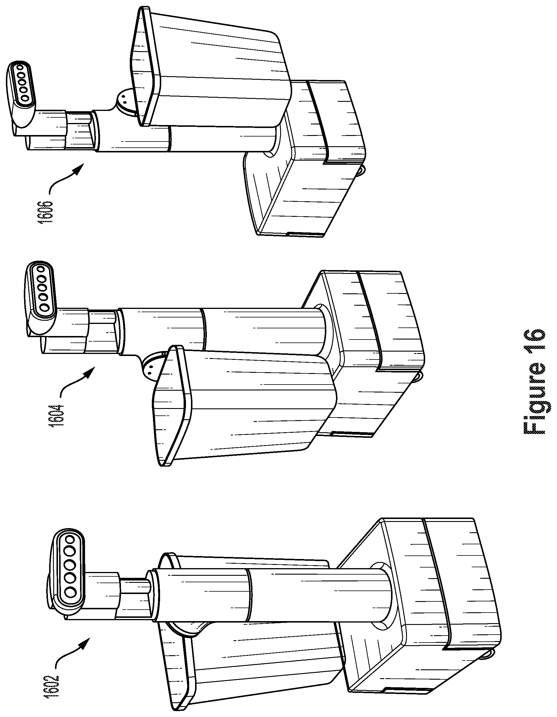
[0099] FIG. 15 shows positions of a rotatable joint having an attached appendage, in accordance with example embodiments. More specifically, rotation of a rotable J0 joint allows a mobile robotic device to position an attached appendage at different positions, including a rear position 1502, a side position 1504, and a front position 1506. In FIG. 15, the attached appendage is illustrated as a tray (e.g., for serving food, drinks, or other items to users). In further examples, other types of appendages may also be attached to the mobile robotic device in a similar manner. For instance, FIG. 16 shows positions of a rotatable joint having a different attached appendage, in accordance with example embodiments. More specifically, a basket (e.g., for collecting waste or other items from users) is illustrated at different positions, including a rear position 1602, a side position 1604, and a front position 1606.
[0100] In some examples, including an attachment point to connect an appendage to the rotatable J0 joint allows for the swapping of different appendages for different robot tasks. For instance, a tray may be attached for tasks involving item delivery, a basket may be attached for tasks involving item collection, and no appendage may be attached for tasks requiring maximum carrying capacity on the back of the robot. For a mobile robotic device including an attachment point to connect an appendage to the rotatable J0 joint, the rest of the mobile robotic device may include any of the aspects described herein with respect to a mobile robotic device having an attached 7DOF robotic arm. Some example embodiments therefore include a mobile robotic device such as illustrated in FIGS. 15 and 16, including a mobile base, a mounting column fixed to the mobile base, a rotatable joint that enables rotation of an appendage relative to the mounting column, and a perception housing comprising at least one sensor, where the mounting column, the rotatable joint, and the perception housing are arranged in a stacked tower such that the rotatable joint is above the mounting column and below the perception housing.
[0101] In further examples, a robotic arm such as the previously illustrated 7DOF robotic arm or some portion thereof may also be attachable to an attachment point such as illustrated in FIG. 13A. In some examples, the robotic arm may therefore also be removable to allow for the attachment of other types of appendages.
III. CONCLUSION
[0102] The present disclosure is not to be limited in terms of the particular embodiments described in this application, which are intended as illustrations of various aspects. Many modifications and variations can be made without departing from its spirit and scope, as will be apparent to those skilled in the art. Functionally equivalent methods and apparatuses within the scope of the disclosure, in addition to those enumerated herein, will be apparent to those skilled in the art from the foregoing descriptions. Such modifications and variations are intended to fall within the scope of the appended claims.
[0103] The above detailed description describes various features and functions of the disclosed systems, devices, and methods with reference to the accompanying figures. In the figures, similar symbols typically identify similar components, unless context dictates otherwise. The example embodiments described herein and in the figures are not meant to be limiting. Other embodiments can be utilized, and other changes can be made, without departing from the spirit or scope of the subject matter presented herein. It will be readily understood that the aspects of the present disclosure, as generally described herein, and illustrated in the figures, can be arranged, substituted, combined, separated, and designed in a wide variety of different configurations, all of which are explicitly contemplated herein.
[0104] A block that represents a processing of information may correspond to circuitry that can be configured to perform the specific logical functions of a herein-described method or technique. Alternatively or additionally, a block that represents a processing of information may correspond to a module, a segment, or a portion of program code (including related data). The program code may include one or more instructions executable by a processor for implementing specific logical functions or actions in the method or technique. The program code or related data may be stored on any type of computer readable medium such as a storage device including a disk or hard drive or other storage medium.
[0105] The computer readable medium may also include non-transitory computer readable media such as computer-readable media that stores data for short periods of time like register memory, processor cache, and random access memory (RAM). The computer readable media may also include non-transitory computer readable media that stores program code or data for longer periods of time, such as secondary or persistent long term storage, like read only memory (ROM), optical or magnetic disks, compact-disc read only memory (CD-ROM), for example. The computer readable media may also be any other volatile or non-volatile storage systems. A computer readable medium may be considered a computer readable storage medium, for example, or a tangible storage device.
[0106] Moreover, a block that represents one or more information transmissions may correspond to information transmissions between software or hardware modules in the same physical device. However, other information transmissions may be between software modules or hardware modules in different physical devices.
[0107] The particular arrangements shown in the figures should not be viewed as limiting. It should be understood that other embodiments can include more or less of each element shown in a given figure. Further, some of the illustrated elements can be combined or omitted. Yet further, an example embodiment can include elements that are not illustrated in the figures.
[0108] While various aspects and embodiments have been disclosed herein, other aspects and embodiments will be apparent to those skilled in the art. The various aspects and embodiments disclosed herein are for purposes of illustration and are not intended to be limiting, with the true scope being indicated by the following claims.
* * * * *
D00000
D00001
D00002
D00003
D00004
D00005
D00006
D00007
D00008
D00009
D00010
D00011
D00012

D00013
D00014
D00015

D00016
D00017

D00018
D00019
D00020

D00021
XML
uspto.report is an independent third-party trademark research tool that is not affiliated, endorsed, or sponsored by the United States Patent and Trademark Office (USPTO) or any other governmental organization. The information provided by uspto.report is based on publicly available data at the time of writing and is intended for informational purposes only.
While we strive to provide accurate and up-to-date information, we do not guarantee the accuracy, completeness, reliability, or suitability of the information displayed on this site. The use of this site is at your own risk. Any reliance you place on such information is therefore strictly at your own risk.
All official trademark data, including owner information, should be verified by visiting the official USPTO website at www.uspto.gov. This site is not intended to replace professional legal advice and should not be used as a substitute for consulting with a legal professional who is knowledgeable about trademark law.