Structured Elements And Methods Of Use
GLOVER; JOHN ; et al.
U.S. patent application number 16/995760 was filed with the patent office on 2020-12-03 for structured elements and methods of use. This patent application is currently assigned to CRYSTAPHASE PRODUCTS, INC.. The applicant listed for this patent is CRYSTAPHASE PRODUCTS, INC.. Invention is credited to JOHN GLOVER, PETER HAM, AUSTIN SCHNEIDER.
| Application Number | 20200376414 16/995760 |
| Document ID | / |
| Family ID | 1000005021640 |
| Filed Date | 2020-12-03 |


| United States Patent Application | 20200376414 |
| Kind Code | A1 |
| GLOVER; JOHN ; et al. | December 3, 2020 |
STRUCTURED ELEMENTS AND METHODS OF USE
Abstract
Structured elements with capabilities for stream flow division and distribution and mitigation of undesired species that exceed those of conventionally available materials are provided. The structured elements provide increased opportunities for surface attraction, retention and coalescence of undesired species in a process stream. The functional contact surfaces of the structured elements can include one or more of the faces of cells, the surfaces of struts connecting cells, the surfaces of nodes connecting struts, and the surfaces of asperities or irregularities caused by channels, flutes, spikes, fibrils or filaments in or on the material surfaces.
| Inventors: | GLOVER; JOHN; (HOUSTON, TX) ; SCHNEIDER; AUSTIN; (HUMBLE, TX) ; HAM; PETER; (HOUSTON, TX) | ||||||||||
| Applicant: |
|
||||||||||
|---|---|---|---|---|---|---|---|---|---|---|---|
| Assignee: | CRYSTAPHASE PRODUCTS, INC. HOUSTON TX |
||||||||||
| Family ID: | 1000005021640 | ||||||||||
| Appl. No.: | 16/995760 | ||||||||||
| Filed: | August 17, 2020 |
Related U.S. Patent Documents
| Application Number | Filing Date | Patent Number | ||
|---|---|---|---|---|
| 15393573 | Dec 29, 2016 | 10744426 | ||
| 16995760 | ||||
| 62294718 | Feb 12, 2016 | |||
| 62273590 | Dec 31, 2015 | |||
| Current U.S. Class: | 1/1 |
| Current CPC Class: | B01J 2219/30491 20130101; B01J 19/30 20130101; B01D 21/0012 20130101; B01J 2219/30246 20130101; B01J 2219/30475 20130101; B01D 21/0087 20130101; B01J 2219/30 20130101; B01J 2219/30483 20130101; B01D 3/008 20130101; B01J 2219/30207 20130101; B01J 2219/30416 20130101; B01J 2219/30269 20130101; B01J 2219/30238 20130101 |
| International Class: | B01D 21/00 20060101 B01D021/00; B01D 3/00 20060101 B01D003/00; B01J 19/30 20060101 B01J019/30 |
Claims
1. A method of distributing the flow of a fluid stream within a process unit, the method comprising: passing the fluid stream through a plurality of structured elements in the process unit, each structured element comprising one or more interconnected unit cells, each unit cell having a frame with a three-dimensional polyhedron structure and a plurality of faces, wherein the faces include a combination of open faces, partially open faces and closed faces, and wherein the frame, the partially open faces and the closed faces each have a plurality of differently-shaped asperities disposed on the surfaces thereof; and contacting the fluid stream with the structured elements as the fluid stream flows through the structured elements, such that the fluid steam is subdivided into substreams.
2. The method of claim 1, wherein the asperities comprise one or more of channels, flutes, spikes, fibrils and filaments.
3. The method of claim 1, wherein the structured elements comprise a plurality of differently-shaped unit cells.
4. The method of claim 1, wherein the asperities comprise one or more of fibrils and filaments.
Description
RELATED APPLICATIONS
[0001] This application is a divisional application and claims the benefit, and priority benefit, of U.S. patent application Ser. No. 15/393,573, filed Dec. 29, 2016, which claims the benefit, and priority benefit, of U.S. Provisional Patent Application Ser. No. 62/273,590, filed Dec. 31, 2015, and U.S. Provisional Patent Application Ser. No. 62/294,718, filed Feb. 12, 2016, the contents of each are incorporated by reference herein in their entirety.
BACKGROUND
Field of the Invention
[0002] The presently disclosed subject matter relates to materials and methods for enhanced treatment of streams to, from and/or within process units.
Description of the Related Art
[0003] It is known in the art to tailor various streams flowing to, from and/or within process units in industrial facilities in order to to improve the efficiency and economics of the process units contained in the facilities. For example, undesired species in streams can foul, clog, contaminate, poison or degrade unit internals. These undesired species can also have negative effects on the performance of units contiguous to, downstream of, or integrated with such units. Additionally, process unit performance depends on the effective division and distribution of streams entering and within the process unit in order to facilitate optimum contact with internals within the process unit. Improvements in this field of technology are desired.
SUMMARY
[0004] The presently disclosed subject matter relates to materials and methods for enhanced treatment of streams to, from and/or within process units.
[0005] In certain illustrative embodiments, a method of flow division and distribution and of filtration and mitigation of undesired species from a stream to a unit is provided. The stream can be passed through and contacted with the surfaces of structured elements disposed in the unit, the structured elements being present in an amount sufficient to facilitate flow division and distribution of the stream and to mitigate the undesired species in the stream. The structured elements can have a contact surface with a surface area ranging from 200 to 800,000 square meters per cubic meter of structured elements. The structured elements can also have a filtration capability able to effectively remove particulates of sizes from 100 nanometers to 11 millimeters.
[0006] In certain aspects, the structured elements can have a contact surface with a surface area of at least 10,000 square meters per cubic meter of structured elements. The structured elements can also have a contact surface with a surface area of up to 800,000 square meters per cubic meter of structured elements. The structured elements can also have a contact surface with a surface area ranging from 10,000 to 800,000 square meters per cubic meter of structured elements.
[0007] In certain aspects, the structured elements can comprise one or more interconnected unit cells, each unit cell having a frame and a plurality of faces. The individual faces can be open, partially open or entirely closed. The frame and plurality of faces of each unit cell can form a three dimensional structure. The three dimensional structure can be a polyhedron, exemplified by the Weaire-Phelan foam-like structure. The polyhedron can be a regular polyhedron or an irregular polyhedron. The three dimensional structure can be a monolith. The monolith can have parallel and non-intersecting channels. The monolith can have irregular, non-intersecting channels. At least 10% of the total area of the faces of the unit cells can be partially or totally obstructed. The unit cells can each have a diameter in the range from 0.5 to 50 millimeters. The structured element can have a plurality of interconnected unit cells comprising a plurality of tortuous flow passageways through the structured element and the stream can be passed through and contacted with the surfaces of the plurality of tortuous flow passageways.
[0008] In certain aspects, the structured element can additionally include a plurality of asperities formed on the unit cells comprising the structured element. The asperities can include one or more of channels, flutes, spikes, fibrils and filaments. The contact surface of the structured element can comprise the surfaces of the plurality of tortuous passageways as well as the interconnected unit cells including their frames, their faces and their asperities.
[0009] In certain illustrative embodiments, a method of mitigation of undesired species from a stream to a process unit is provided. The stream can be passed through one or more structured elements in the unit, the structured elements being present in an amount sufficient to mitigate the undesired species in the stream. The stream can be contacted with the surfaces of the structured elements to mitigate the undesired species in the stream. The structured elements can have a contact surface with a surface area ranging from 200 to 800,000 square meters per cubic meter of structured elements and a filtration capability able to effectively remove particulates of sizes from 100 nanometers to 11 millimeters. In certain aspects, the structured elements can also have a contact surface with a surface area of at least 10,000 square meters per cubic meter of structured elements. The structured elements can also have a contact surface with a surface area of up to 800,000 square meters per cubic meter of structured elements. The structured elements can also have a contact surface with a surface area ranging from 10,000 to 800,000 square meters per cubic meter of structured elements.
[0010] In certain illustrative embodiments, a method of facilitating flow division and distribution of a stream to a process unit is provided. The stream can be passed through structured elements in the unit, the structured elements being present in an amount sufficient to facilitate flow division and distribution of the stream. The stream can be contacted with the structured elements to facilitate flow division and distribution of the stream. The structured elements can have a contact surface with a surface area ranging from 200 to 800,000 square meters per cubic meter of structured elements and a filtration capability able to effectively remove particulates of sizes from 100 nanometers to 11 millimeters. In certain aspects, the structured elements can also have a contact surface with a surface area of at least 10,000 square meters per cubic meter of structured elements. The structured elements can also have a contact surface with a surface area of up to 800,000 square meters per cubic meter of structured elements. The structured elements can also have a contact surface with a surface area ranging from 10,000 to 800,000 square meters per cubic meter of structured elements.
BRIEF DESCRIPTION OF THE DRAWINGS
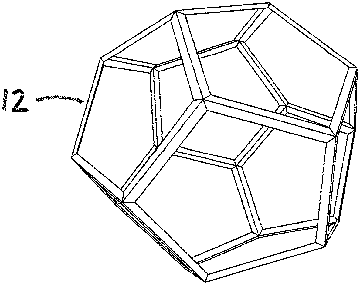
[0011] FIG. 1 is a perspective view of a unit cell for a structured element, the unit cell having a dodecahedron shape, in accordance with an illustrative embodiment of the presently disclosed subject matter.
[0012] FIG. 2 is a perspective view of a unit cell for a structured element, the unit cell having a dodecahedron shape with a plurality of blocked openings in accordance with an illustrative embodiment of the presently disclosed subject matter.
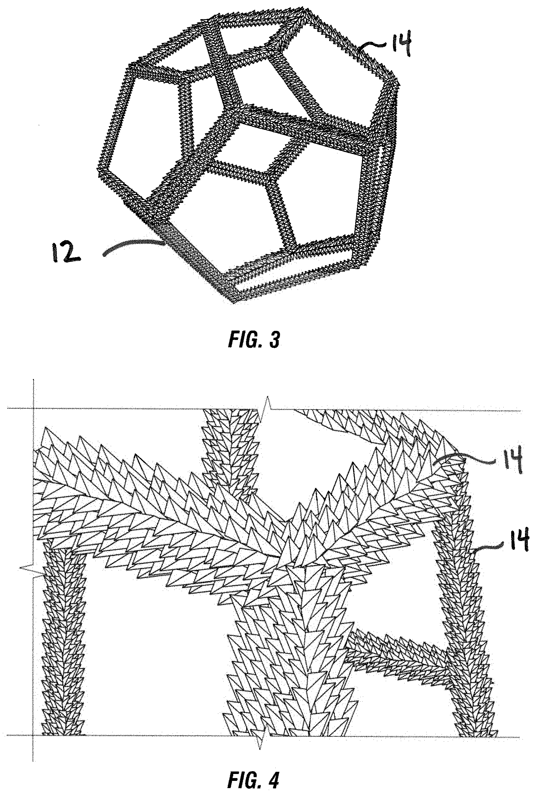
[0013] FIG. 3 is a perspective view of a unit cell for a structured element, the unit cell having a dodecahedron shape with a surface roughened by asperities and irregularities in accordance with an illustrative embodiment of the presently disclosed subject matter.
[0014] FIG. 4 is a zoomed-in perspective view of the unit cell of FIG. 3.
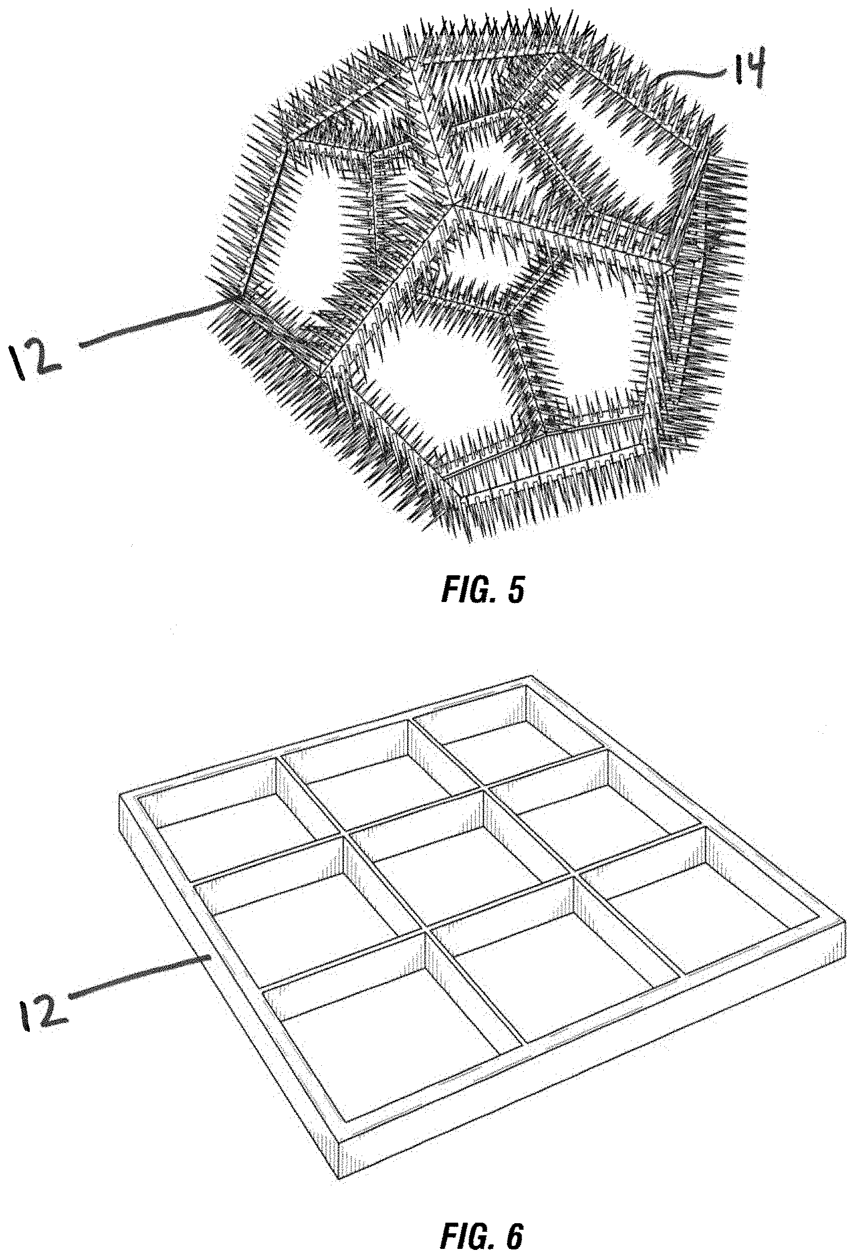
[0015] FIG. 5 is a perspective view of a unit cell for a structured element, the unit cell having a dodecahedron shape with a strutted or fibrillar surface in accordance with an illustrative embodiment of the presently disclosed subject matter.
[0016] FIG. 6 is a perspective view of a structured element comprised of unit cells and having a monolithic shape in accordance with an illustrative embodiment of the presently disclosed subject matter.
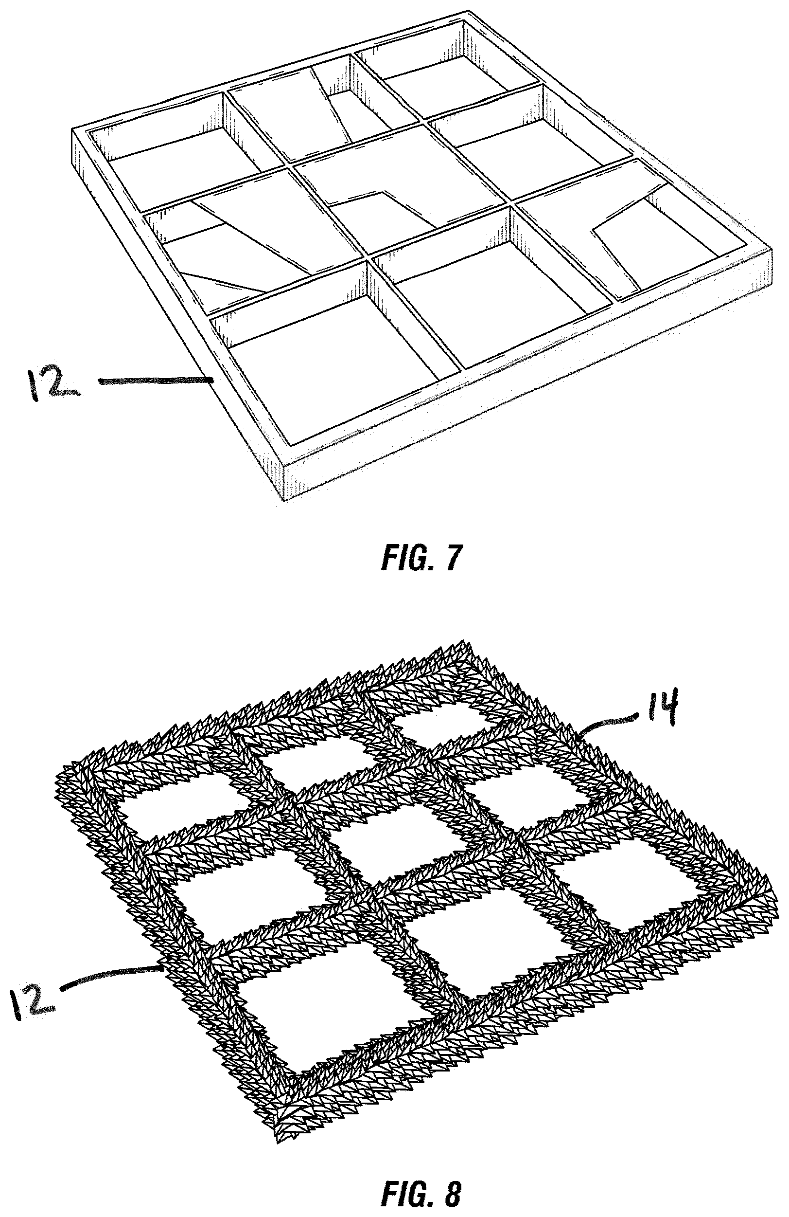
[0017] FIG. 7 is a perspective view of a structured element comprised of unit cells and having a monolithic shape and a plurality of blocked openings in accordance with an illustrative embodiment of the presently disclosed subject matter.
[0018] FIG. 8 is a perspective view of a structured element comprised of unit cells and having a monolithic shape with a roughened surface in accordance with an illustrative embodiment of the presently disclosed subject matter.
[0019] FIG. 9 is a perspective view of a structured element comprised of unit cells and having a monolithic shape with a strutted or fibrillar surface in accordance with an illustrative embodiment of the presently disclosed subject matter.
[0020] FIG. 10 is a graph comparing filtration capability for conventional materials and the presently disclosed materials in accordance with an illustrative embodiment of the presently disclosed subject matter.
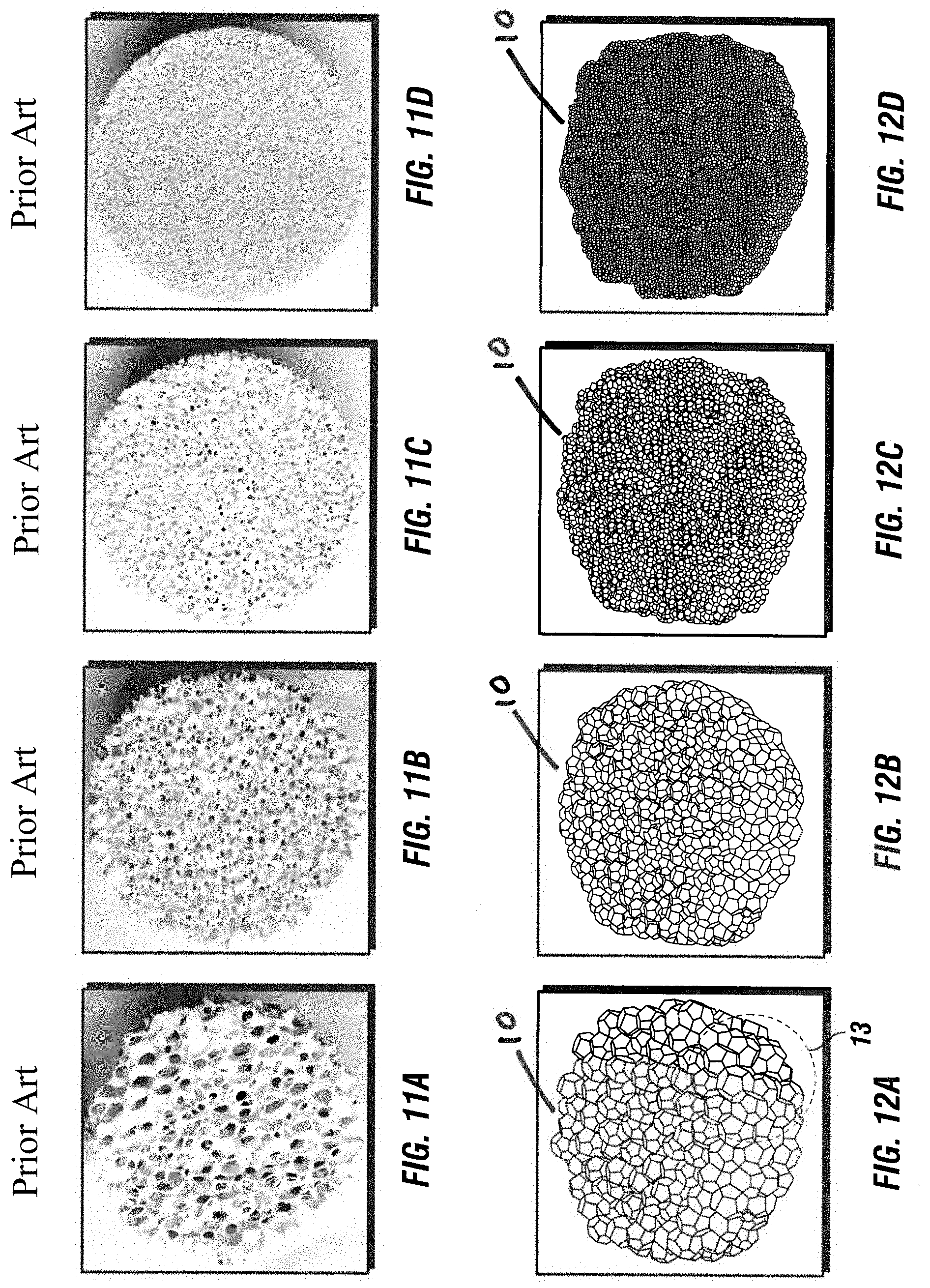
[0021] FIGS. 11A-D are images of conventional porous filtration media having various sized openings.
[0022] FIGS. 12A-D are images of the presently disclosed structured elements having various sized openings in accordance with illustrative embodiments of the presently disclosed subject matter.
[0023] FIG. 13 is a zoomed-in perspective view of the structured element of FIG. 12A.
[0024] While the presently disclosed subject matter will be described in connection with the preferred embodiment, it will be understood that it is not intended to limit the presently disclosed subject matter to that embodiment. On the contrary, it is intended to cover all alternatives, modifications, and equivalents, as may be included within the spirit and the scope of the presently disclosed subject matter as defined by the appended claims.
DETAILED DESCRIPTION
[0025] The presently disclosed subject matter relates to materials and methods for enhanced treatment of streams to, from and/or within process units. Units typically have internals to tailor streams entering and/or within the unit. Units also have internals to undertake desired unit operations, such as, for example, catalytic reactions and/or mass transfer. Stream treatment functions can include attracting, retaining and/or otherwise mitigating undesired species and/or ensuring effective stream flow division and distribution. The undesired species can include, without limitation, solid particulates, molecular species and entrained fluids.
[0026] Units can have streams entering the units as feeds, internal streams (such as recycle streams) within the units and streams exiting the units as products. The handling of these streams can involve a variety of activities including but not limited to (i) mitigating undesired species, (ii) ensuring effective stream flow division and distribution, (iii) performing desired unit operations such as chemical reactions and mass transfer including component separation, and (iv) generating and recovering streams as finished products or as feeds to other units. These activities can be carried out in discrete zones within units or combined as appropriate.
[0027] As an example of a simple configuration frequently utilized in industry, many units have a stream treating zone positioned upstream of a stream processing zone, both contained within the same unit. In such a configuration and in the majority of configurations utilized in industry, the roles of the treating zone are to provide to the processing zone a stream whose flow is effectively divided and distributed and/or that is substantially free of undesired species. However, many other configurations of these functionalities and combinations of these functionalities may be designed into units.
[0028] In some cases, treating zones can be installed for the sole purpose of dividing and distributing stream flow, or for the sole purpose of mitigating undesired species. Treating zones can be composed of separate layers of materials specifically designed to accomplish these purposes. For example, layers of different forms of media (including different sizes or shapes or structures or compositions or the like) can be installed with each layer targeted at mitigating a specific set of undesired species. Layers can be composed of media whose purposes are to both mitigate undesired species and facilitate stream division and distribution. Layers may be installed in any order and in any location as dictated by the functions to be performed. Units may have only one treating zone or one processing zone, one of each, one of each and multiples of the other, multiples of both or combinations of both. Combination is meant to include zones which have both treating and processing functionalities.
[0029] Treating zones can have useful lives primarily dictated by their capacity to attract, retain and/or otherwise mitigate undesired species and/or their ability to effectively divide and distribute the flow of streams passed through them. Treating zones can become blocked or clogged over time and eventually exhaust their capacities to attract, retain, and mitigate undesired species and/or divide and distribute the flow of streams. As these capacities are exhausted, insufficiently-processed streams can progress into downstream zones. Treating zone exhaustion can result in increased pressure drop in the unit itself which can necessitate unit shutdown to rejuvenate (via, for examples, regeneration or partial or complete replacement) the contents of the treating zone and, perhaps, the contents of downstream zones.
[0030] A function of processing zones is to process the suitably tailored streams exiting the treating zones. Examples of such processing include (i) molecular conversion via thermal, pressure and/or catalytic means and (ii) component separation via distillation, extraction or the like. Some materials and media used in such processing zones can have a useful "on-oil" life. In process units, for example, where the media in the processing zone are catalysts, the capability of the catalytic media can degrade over time due to catalyst deactivation caused, for examples, by coking or by agglomeration or conversion of catalytic species. A typical response to processing zone catalyst deactivation is to increase unit temperature in order to sustain catalytic performance. Maximum allowed temperature, when reached, will require unit shutdown. Improved treatment zones can facilitate enhanced performance of catalytic processing zones by: [i] prolonging catalyst life via providing stream flows that are more dispersed and distributed, [ii] prolonging catalyst life via providing stream flows containing reduced concentrations of undesired species, and [iii] advantageously allowing the use of more productive catalyst media, i.e., more active media or more long-lasting media.
[0031] Various conventional means exist for attracting, retaining and/or otherwise mitigating undesired species in streams passing through treating zones. For example, absorbents or otherwise active materials can be used to render undesired chemical species inert, cause them to be ejected from the unit in an effluent stream or converted into larger particulate matter that can be effectively removed using traditional filtration solutions. Undesired chemical species including reaction products such as iron sulfides and the like can form small particulates. Existing filtration technologies have limitations regarding the particulate sizes they can remove and have limited abilities to deal with undesired chemical species.
[0032] Conventional filtration media are also utilized in treating zones within units. However, these media can become clogged and blocked, which causes increases in pressure drop across the filter system as well as the unit itself which may require that the entire unit be taken off-line to remove and replace spent filter media and systems.
[0033] Filter system backwashing has also been used to remove filtered particulates. These change-outs and/or cleanings require costly interruptions with accompanying costs due to unit downtime, filter system expenses and maintenance effort. Such change-outs and/or cleanings also incur operating risks associated with unit shutdowns, startups and maintenance.
[0034] Porous filtration media have been utilized to attract and retain undesired species found in streams. Conventional porous filtration media are typically composed of ceramics or metals capable of withstanding the severe operating conditions in industrial units. The primary filtration mechanism of such media has been thought to occur within the pores of the media. The ability of such media to effectively mitigate such species has hitherto been correlated with pore size distribution, typically measured by "ppi" or "pores per inch." Conventional porous filtration media can be commercially manufactured with ppi ranging from about 10 to 100. The ability of such media to attract and retain undesired species depends not only on its ppi but also on the internal surface area of the media. For example, 10 ppi conventional porous media has internal surface area of about 300 square meters per cubic meter of media and has the ability to attract and retain undesired species sized from about 650 to 2000 microns. A 100 ppi conventional porous media has internal surface area of about 2400 square meters per cubic meter of media and has the ability to attract and retain undesired species sized from about 40 to 500 microns. Mitigating undesired species with sizes below 40 microns is not commercially feasible with conventional media. Also, mitigating undesired species ranging in size from, say, 40 to 2000 microns would require utilization of multiple grades of conventional media, each with its own ppi structure and associated internal surface area. Attempts to mitigate species larger than the capable maximum (2000 microns for 10 ppi media and 500 microns for 100 ppi media) results in complete performance debilitation of conventional media.
[0035] Porous media is frequently used in treating zones of units to achieve flow division and distribution to downstream processing zones in the same units. The prevailing thinking regarding this subject has been that treating zone flow division and distribution is enhanced as decreased pore size provides increased division and distribution capability. The presently disclosed subject matter demonstrates that the amount and structure of the contact surface area of treating zone media determines the efficacy of stream flow division and distribution as well as undesired species mitigation.
[0036] Providing optimum stream treatment systems requires the proper selection, design, fabrication, installation, operation and maintenance of such systems. Key performance parameters to be considered include the robustness of the materials selected to attract, retain and/or otherwise mitigate undesired species and/or the configuration and assembly of such materials so as to provide effective stream division and distribution.
[0037] Processing zones can be located within the same unit as the treating zone or in a vessel downstream of the vessel containing the treating zone. Zones within units are utilized to treat and/or process streams. Some zones simultaneously treat and process streams. More typically, streams passing through treating zones are subsequently passed to processing zones.
[0038] In certain illustrative embodiments, the presently disclosed subject matter can be employed in zones that simultaneously treat and process streams or in stand-alone treating zones. Specifically, the presently disclosed subject matter can: (i) more fully utilize the capability of the unit internals to attract, retain and/or otherwise mitigate undesired species; (ii) more effectively divide and distribute streams to processing zones within units; (iii) reduce the costs of such treating zone solutions while also allowing for maximized utilization of capabilities of the processing zones of such units; and (iv) result in substantial increases in unit profitability.
[0039] In certain illustrative embodiments, the presently disclosed subject matter comprises structured elements with capabilities for stream flow division and distribution and mitigation of undesired species that exceed those of conventionally available materials. When used in units, the structured elements described herein have a number of advantages when compared to prior art materials. For treating zones within units, the advantages include: (i) reducing the depth of the treating zone required, (ii) attracting, retaining and/or otherwise mitigating undesired species unable to be handled by prior art materials and (iii) providing flow division and distribution to processing zones more effectively than prior art materials. For processing zones, the advantages include: (i) having the benefit of cleaner, better divided and/or distributed streams exiting from treating zones, (ii) allowing the utilization of more effective processing zone internals, e.g., more active catalyst types or morphologies, and (iii) creating additional processing zone space to increase loadings of catalysts, absorbents or other internals. For the unit as a whole, the advantages include: (i) reducing the need for unit disruptions, including downtimes, with attendant loss of unit productivity, (ii) reduced operating risks associated with such disruptions and (iii) increased unit reliability and profitability.
[0040] Conventional filtration systems in treating zones using porous media have been pore-centric with filtration thought to occur within the pores of the filter media. Recent studies have revealed that the primary filtration mechanism in such media is attraction, retention and/or otherwise mitigation of undesired species on the contact surfaces within the media. In certain illustrative embodiments, the presently disclosed subject matter comprises structured elements having contact surface architecture that is superior to that found in conventional filter media. The contact surface architecture is more amenable to attracting, retaining and/or otherwise mitigating undesired species and/or to facilitating stream flow division and distribution.
[0041] In certain illustrative embodiments, the structured elements have multifaceted, three-dimensioal geometry with significantly increased contact surface area relative to conventional material architecture. Structured elements can comprise interconnected unit cells, each unit cell having a frame and a plurality of faces. The individual faces can be open, partially open or closed. At least 10% of the total area of the faces of the unit cells can be closed. The structured elements can additionally include a plurality of asperities formed on the unit cells. Asperities can include one or more of channels, flutes, spikes, fibrils and filaments. The structured elements can have a plurality of tortuous passageways through the structure via the openings in the faces of the interconnected unit cells.
[0042] Representative three dimensional architectures of the structured element unit cells can include regular and irregular polyhedra and monoliths.
[0043] The contact surface of the structured elements can comprise the surfaces of both their tortuous passageways and their unit cells including the frames, faces and asperities of the unit cells. The contact surface of the materials of the presently disclosed subject matter exceeds that of prior materials.
[0044] These contact surfaces provide the primary vehicle for mitigating undesired species via attraction, retention, adhesion, absorption, coalescence, agglomeration, capillary action and the like. This results in increased mitigation of undesired species within treating zones which leads directly to improved unit performance.
[0045] In certain illustrative embodiments, the structured elements have tortuosity and boundary layer conditions which enhance the ability of the material to attract, retain and/or otherwise mitigate particulate and molecular species. For example, in certain illustrative embodiments, the presently disclosed materials can attract and retain species having sizes as small as 200 nanometers, and in certain illustrative embodiments, as small as 100 nanometers.
[0046] In certain illustrative embodiments, the structured elements can be engineered to have structural characteristics beyond the geometric bounds set by the natural formations of foams, gels and extrusions which are used to form conventional porous media. The structured elements can have "active" surface features that improve attraction, retention and/or other mitigation capabilities and enhance flow division and distribution.
[0047] For example, in certain illustrative embodiments, the active surface features can include: (i) engineered blockage or partial blockage of unit cell faces; (ii) designed roughness of surfaces plus designed surface asperities or irregularities such as channels, flutes, spikes, fibrils, filaments and the like; (iii) increased tortuous surfaces and surface area of passageways; (iv) regions allowing pooling and settling of liquids; and (v) increased laminar flow and boundary layer zones, wherein van der Waals adhesion forces are magnified.
[0048] Active surface features of pooling and settling regions include enhanced capture of small particles which, according to Stokes Law, require more time to pool and settle than larger particles.
[0049] Furthermore, it is known that van der Waals adhesion forces become dominant for collections of very small particles (i.e. 250 microns or smaller). Van der Waals adhesion forces are dependent on surface topography, and if there are surface asperities or protuberances which result in greater area of contact between particles or a particle and a wall, van der Waals forces of attraction as well as the tendency for mechanical interlocking increase.
[0050] In certain illustrative embodiments, the structured elements have an engineered architecture that elicits enhanced performance beyond existing porous or cellular materials due to improved surface architecture and conditions. The structured elements can have an enlarged contact surface area containing thin film boundary layers within which molecular attraction and retention plus Van der Waals adhesion forces are magnified.
[0051] In certain illustrative embodiments, surface features of the structured elements can include surfaces that are wholly or partially composed of, or coated with, materials that enhance mitigation of undesired species. An illustrative example is wash coating with a material which helps attract and retain metal molecular species such as arsenic and vanadium, both of which are powerful catalyst deactivators or poisons.
[0052] The structured elements provide increased opportunities for surface attraction, retention and coalescence of undesired species. In certain illustrative embodiments, the functional contact surfaces of the structured elements can include one or more of: (i) the faces of cells, (ii) the surfaces of struts connecting cells, (iii) the surfaces of nodes connecting struts, and (iv) the surfaces of asperities or irregularities caused by channels, flutes, spikes, fibrils or filaments in or on the surfaces of all the above. The functional contact surfaces of the structured elements can be manufactured or modified to enhance coalescence, chemical reaction, agglomeration of atoms into larger species, extraction, adsorption, and the like in the process units.
[0053] In certain illustrative embodiments, the structured elements can facilitate flow division and distribution in units. It has been learned that flow division and distribution enhancement can be attributed not only to tortuous mixing, but also, in certain illustrative embodiments, to the development of thin films on the surfaces of the structured elements. These films and surfaces can provide a vehicle for division and flow distribution. Thus, the focus of flow division and distribution performance is shifted from pore size and pore volume to contact surfaces, surface area and, importantly, surface asperities and irregularities.
[0054] In certain illustrative embodiments, the structured elements can have appropriately engineered architectures that attract, retain and/or otherwise mitigate a broader range of undesired species than conventional materials. This provides the important economic benefit of decreasing the number of layers of media "grades" (and the space required to contain them) in a unit's treating zone(s) and freeing valuable space for added unit internals (such as catalyst) in the unit's processing zone(s). In certain illustrative embodiments, the structured elements comprise materials having an internal void fraction of 60% or greater. In certain illustrative embodiments, the structured elements can begin with cells that are 0.5 to 50 millimeters in size.
[0055] In certain illustrative embodiments, the structured elements can comprise polyhedral shaped materials. The polyhedral shapes can include, for example, tetrahedra, cubes, octahedra, dodacahedra and isosahedra. The polyhedral shapes can be formed from a plurality of interconnected unit cells comprising polygonal shaped materials that are positioned together to form a combined structure. Further, the structured elements can comprise reticulated ceramics as well as any other cellular ceramics including monolithic structures.
[0056] Various illustrative embodiments of the structured element unit cells are shown in FIGS. 1-5. FIG. 1 shows a standard dodecahedron-shaped unit cell, which can be for example, the building block for a reticulated ceramic. FIG. 2 shows the dodecahedron-shaped unit cell having approximately 50% blocked openings. FIG. 3 shows the dodecahedron-shaped unit cell having a roughened surface. FIG. 4 shows a close up view of the dodecahedron-shaped unit cell of FIG. 3, to further illustrate the roughened surface. FIG. 5 shows the dodecahedron-shaped unit cell having a fibrillar surface. FIGS. 12A-12D are representative views of the structured elements composed of a plurality of unit cells wherein the unit cells have different sizes (measured in pores per inch). FIG. 12E, a zoomed portion of FIG. 12A, illustrates the surface features of the structured elements that produce the significant increase in contact surface area relative to conventional materials, in certain illustrative embodiments. FIG. 6 shows a structured element having a standard monolithic structure. FIG. 7 shows the monolithic structure having approximately 50% blocked openings. FIG. 8 shows the monolithic structure having a roughened surface. FIG. 9 shows the monolithic structure having a spiked or fibrillar surface.
[0057] In certain illustrative embodiments, the structured elements comprise materials having a geometric contact surface area in the range from 200 to 800,000 square meters per cubic meter of said structured elements. In certain aspects, the structured elements can have a contact surface with a surface area of at least 10,000 square meters per cubic meter of structured elements. The structured elements can also have a contact surface with a surface area of up to 800,000 square meters per cubic meter of structured elements. The structured elements can also have a contact surface with a surface area ranging from 10,000 to 800,000 square meters per cubic meter of structured elements.
[0058] In certain illustrative embodiments, the range of contact surface area of the structured elements of the presently disclosed subject matter is significantly larger than the contact surface area range of prior art materials. Moreover, specific grades of structured elements have a significantly broader range of ability to attract and retain undesired species. As examples, structured elements corresponding to 10 ppi conventional media are capable of attracting and retaining species of size ranging from 20 to 2000 microns and structured elements corresponding to 100 ppi are capable of attracting and retaining species of size ranging from 0.1 to 500 microns.
[0059] A graphical comparison of filtration capability for conventional materials and the presently disclosed materials is shown in FIG. 10. The graph shows the filtration ranges for both prior art materials (as described in, e.g., Paragraph 28 herein) and the presently disclosed materials with particle sizes shown in microns on the x axis. The Standard Structure A line corresponds to the filtration capability of conventional prior art 10 ppm media. This media is capable of filtering particulate matter from 650 to 2000 microns in size. The Standard Structure B line corresponds to the filtration capability of conventional prior art 100 ppm media. This media is capable of filtering particulate matter from 40 to 500 microns in size. These two represent the upper and lower ppi limits of conventional materials that can be commercially manufactured and used. As shown in FIG. 10, there is a gap between the upper end of the B line (500 microns) and the lower end of the A line (650 microns). If a specific process application needed to filter particulates across the entire 40 to 2000 micron range, both the A and B structures would be required plus another structure (of approximately 50 ppi) to bridge the 500 to 650 micron gap. This would mean three different grades of media in three different layers in the unit must be utilized.
[0060] By comparison, the Structured Elements line of FIG. 10 shows the capability of only one grade of the presently disclosed materials, in certain illustrative embodiments. This grade, when used alone, can filter particulates ranging in size from 20 to 2000 microns, and thus corresponds with the entire range of both the Standard Structure A line and the Standard Structure B line, and beyond. Thus, as explained previously herein, the Structured Elements can filter particulates that are both smaller and larger than feasible with prior art media. For example, the Structured Elements can filter particulates as small as 0.1 microns (100 nanometers) and as large as 11 millimeters, in certain illustrative embodiments.
[0061] FIGS. 11A-11D and 12A-12D are comparative views of conventional materials and the presently disclosed structured elements according to certain illustrative embodiments. The conventional materials of FIGS. 11A-11D have sizes of approximately ten (10) (FIG. 11A), thirty (30) (FIG. 11B), fifty (50) (FIG. 11C) and eighty (80) (FIG. 11D) ppi, respectively. The structured elements of FIGS. 12A-12D are different and distinguishable in structure from those of FIGS. 11A-11D due to the presence of face blockage and surface roughness and asperities (as illustrated in FIG. 12E which is a zoomed portion of 12A) which advantageously provide a significant and measurable increase in contact surface area relative to conventional materials. According to certain illustrative embodiments, and as shown in FIG. 13, the unit cells that make up the structured elements can comprise a random mix of individual unit cells having, for example, various types of asperities and/or one or more blocked openings.
[0062] In certain illustrative embodiments, each of the structured elements in the images in FIGS. 12A-12D can contain a variety of blockages, surface roughness, and asperities. Geometrical models have been produced to estimate the relative increase of surface area that these different combinations are able to generate. For example, in certain illustrative embodiments, the structured element in FIG. 12A could have a surface area as low as 260 square meter per cubic meter and as high as 131,700 square meter per cubic meter. In certain illustrative embodiments, the structured element in FIG. 12B could have a surface area as low as 625 square meter per cubic meter and as high as 305,000 square meter per cubic meter. In certain illustrative embodiments, the structured element in FIG. 12C could have a surface area as low as 1223 square meter per cubic meter and as high as 556,500 square meter per cubic meter. In certain illustrative embodiments, the structured element in FIG. 12D could have a surface area as low as 1697 square meter per cubic meter and as high as 834,600 square meter per cubic meter. More in depth modeling has been performed to demonstrate surface areas exceeding 1,000,000 square meter per cubic meter provided sufficient structures and the preferred combination of blockages, roughness, and asperities. The structure in FIG. 12A could provide enough variability in surface area to perform the same function as FIGS. 11A-11D, vastly shrinking filtration system size and the number of layers required for proper function. Similar comparisons can be made about FIGS. 12B, C, and D, but it can also be said surface areas which could not be physically achieved in FIGS. 11A-11D are surpassed by more than 2 orders of magnitude in the structures represented in FIGS. 12A-12D, in certain illustrative embodiments.
[0063] Various methods of utilizing the structured elements in or in connection with a unit are disclosed herein. For example, in certain illustrative embodiments, a method of mitigating undesired species within and providing effective flow division and distribution of one or more fluid streams is provided. The mitigation can involve retention, capture, trapping, isolation, neutralization, removal, agglomeration, coalescence, transformation or otherwise rendering said undesired species impotent. The undesired species can include small particulates, entrained matter, undesired chemicals, extraneous contaminants, and the like. A treating zone of the structured elements can be provided whereby the structured elements: (i) have sufficient voidage, surface area and passageway tortuosity; (ii) have a plurality of surfaces within said elements sufficient to facilitate both mitigation of the undesired species and effective flow division and distribution; and (iii) have a plurality of tortuous flow passageways to facilitate both mitigation of undesired species on the surfaces of the structured elements and unimpeded passage of the streams thru the treating zone. The effluent from the treating zone can be fed to a processing zone located downstream in the same unit. Asperities and irregularities such as spikes and fibrils can be created on the surfaces of the structured elements. The faces of the structured elements can also be blocked or partially blocked. In another aspect, a method of removing contaminants from a contaminated feed stream is provided. The contaminated feed stream can be passed through a layer of structured elements, the layer of structured elements being in an amount sufficient to substantially filter the contaminant from the feed stream. The contaminated feed stream can be contacted with the surfaces of the structured elements to remove the contaminants from the contaminated feed stream.
[0064] In certain illustrative embodiments, the stream that is treated with the structured elements is an industrial process stream and the unit is an industrial process unit. For example, and without limitation, the industrial process stream can be a hydrocarbon or an inorganic stream, and the industrial process unit can be a hydrotreater, a still or an extractor.
[0065] It is to be understood that the presently disclosed subject matter is not to be limited to the exact details of construction, operation, exact materials, or embodiments shown and described, as obvious modifications and equivalents will be apparent to one skilled in the art. Accordingly, the presently disclosed subject matter is therefore to be limited only by the scope of the appended claims.
* * * * *
D00000
D00001
D00002
D00003
D00004
D00005
D00006
D00007
XML
uspto.report is an independent third-party trademark research tool that is not affiliated, endorsed, or sponsored by the United States Patent and Trademark Office (USPTO) or any other governmental organization. The information provided by uspto.report is based on publicly available data at the time of writing and is intended for informational purposes only.
While we strive to provide accurate and up-to-date information, we do not guarantee the accuracy, completeness, reliability, or suitability of the information displayed on this site. The use of this site is at your own risk. Any reliance you place on such information is therefore strictly at your own risk.
All official trademark data, including owner information, should be verified by visiting the official USPTO website at www.uspto.gov. This site is not intended to replace professional legal advice and should not be used as a substitute for consulting with a legal professional who is knowledgeable about trademark law.