Electrosurgical Instrument With Fluid Diverter
Witt; David A. ; et al.
U.S. patent application number 16/997136 was filed with the patent office on 2020-12-03 for electrosurgical instrument with fluid diverter. The applicant listed for this patent is Ethicon LLC. Invention is credited to Chad P. Boudreaux, Kevin L. Houser, Eric M. Roberson, Frederick E. Shelton, IV, Geoffrey S. Strobl, David A. Witt, David C. Yates.
| Application Number | 20200375651 16/997136 |
| Document ID | / |
| Family ID | 1000005023076 |
| Filed Date | 2020-12-03 |


View All Diagrams
| United States Patent Application | 20200375651 |
| Kind Code | A1 |
| Witt; David A. ; et al. | December 3, 2020 |
ELECTROSURGICAL INSTRUMENT WITH FLUID DIVERTER
Abstract
An end effector of an electrosurgical device may include a discharge port in communication with a first fluid path, an aspiration port in communication with a second fluid path, a first and second electrode, and a diverter in mechanical communication with the two electrodes. The diverter may receive, on its surface, a fluid emitted by the discharge port, and maintain a contact of the fluid with the first and second electrodes. The diverter may be further configured to prevent an aspiration, by the aspiration port, of the fluid on its surface. An electrosurgical device may include a source port in communication with a first fluid path, an evacuation port in communication with a second fluid path, a first and second electrode, and a housing. The device may include a shaft extending distally from the housing and the end effector as described above.
| Inventors: | Witt; David A.; (Maineville, OH) ; Shelton, IV; Frederick E.; (Hillsboro, OH) ; Yates; David C.; (Morrow, OH) ; Boudreaux; Chad P.; (Cincinnati, OH) ; Roberson; Eric M.; (Lebanon, OH) ; Houser; Kevin L.; (Springboro, OH) ; Strobl; Geoffrey S.; (Williamsburg, OH) | ||||||||||
| Applicant: |
|
||||||||||
|---|---|---|---|---|---|---|---|---|---|---|---|
| Family ID: | 1000005023076 | ||||||||||
| Appl. No.: | 16/997136 | ||||||||||
| Filed: | August 19, 2020 |
Related U.S. Patent Documents
| Application Number | Filing Date | Patent Number | ||
|---|---|---|---|---|
| 15274559 | Sep 23, 2016 | 10751117 | ||
| 16997136 | ||||
| Current U.S. Class: | 1/1 |
| Current CPC Class: | A61B 18/14 20130101; A61B 2018/00101 20130101; A61B 18/148 20130101; A61B 2018/00922 20130101; A61B 2018/00196 20130101; A61B 2018/00035 20130101; A61B 2018/0016 20130101; A61B 2018/00083 20130101; A61B 2018/00589 20130101; A61B 2218/002 20130101; A61B 2218/007 20130101; A61M 2025/0073 20130101; A61B 2018/00595 20130101 |
| International Class: | A61B 18/14 20060101 A61B018/14 |
Claims
1. An electrosurgical device comprising: a proximal fluid source port and a first fluid path in fluid communication with the proximal fluid source port; a proximal fluid evacuation port and a second fluid path in fluid communication with the proximal fluid evacuation port; a first electrode configured to be in electrical communication with a first terminal of an energy supply having a first polarity and a second electrode configured to be in electrical communication with a second terminal of the energy supply having an opposing polarity to the first terminal; a housing; a shaft extending distally from the housing; and an end effector, disposed at a distal end of the shaft, the end effector comprising: a distal fluid discharge port in fluid communication with the first fluid path; a distal fluid aspiration port in fluid communication with the second fluid path; an exposed distal portion of the first electrode and an exposed distal portion of the second electrode; and a diverter comprising a first surface, a first terminal lateral side in mechanical communication with an inner surface of the exposed distal portion of the first electrode, and a second terminal lateral side in mechanical communication with an inner surface of the exposed distal portion of the second electrode, wherein the first surface comprises a plurality of features configured to direct a flow of the fluid on the first surface and wherein the plurality of features comprises a plurality of protrusions or recesses.
2. The electrosurgical device of claim 1, wherein the diverter is configured to maintain a contact between a fluid, a surface of the exposed distal portion of the first electrode, and a surface of the exposed distal portion of the second electrode.
3. The electrosurgical device of claim 1, wherein the distal fluid discharge port comprises an aperture comprising a circular opening, a semi-lunar opening, or a slit opening.
4. The electrosurgical device of claim 1, wherein a portion of the first fluid path disposed proximal to the distal fluid discharge port is configured to impart a turbulent flow to a fluid flowing therethrough.
5. The electrosurgical device of claim 1, wherein the distal fluid discharge port comprises a first cannula in mechanical communication with the inner surface of the exposed distal portion of the first electrode and a second cannula in mechanical communication with the inner surface of the exposed distal portion of the second electrode.
6. The electrosurgical device of claim 5, wherein the distal fluid discharge port comprises a plurality of pores in the first cannula and the second cannula.
7. The electrosurgical device of claim 1, wherein the distal fluid discharge port is disposed on a distal end of an aspiration tube.
8. The electrosurgical device of claim 7, wherein the aspiration tube is configured to be placed in a retracted configuration or in an extended configuration
9. The electrosurgical device of claim 8, wherein the housing further comprises a slide switch configured to place the aspiration tube in the retracted configuration or in the extended configuration.
10. The electrosurgical device of claim 8, wherein the distal fluid discharge port is positioned under and proximal to a distal end of the diverter when the aspiration tube is placed in the retracted configuration.
11. The electrosurgical device of claim 8, wherein the distal fluid discharge port is positioned under and distal to a distal end of the diverter when the aspiration tube is placed in the extended configuration.
12. The electrosurgical device of claim 1, wherein the diverter further comprises a third electrode.
13. The electrosurgical device of claim 12, wherein a top surface of the third electrode comprises at least a portion of the first surface of the diverter.
14. The electrosurgical device of claim 13, wherein the plurality of features comprise a plurality of protrusions disposed on the top surface of the third electrode.
15. The electrosurgical device of claim 12, wherein the third electrode is disposed through at least a part of an entire thickness of the diverter.
16. The electrosurgical device of claim 1, wherein the exposed distal portion of the first electrode and the exposed distal portion of the second electrode each has a fabiform cross-section.
17. The electrosurgical device of claim 16, wherein the first terminal lateral side of the divert is disposed against an inner surface of the fabiform cross-section of the exposed distal portion of the first electrode, and wherein the second terminal lateral side of the divert is disposed against an inner surface of the fabiform cross-section of the exposed distal portion of the second electrode.
18. The electrosurgical device of claim 17, wherein the distal fluid discharge port comprises a first cannula in mechanical communication with the inner surface of the fabiform cross-section of the exposed distal portion of the first electrode and a second cannula in mechanical communication with the inner surface of the of the fabiform cross-section of the exposed distal portion of the second electrode.
Description
CROSS-REFERENCE TO RELATED APPLICATION
[0001] This application is a continuation application claiming priority under 35 U.S.C. .sctn. 120 to U.S. patent application Ser. No. 15/274,559, entitled ELECTROSURGICAL INSTRUMENT WITH FLUID DIVERTER, filed Sep. 23, 2016, now U.S. Patent Application Publication No. 2018/0085156, the entire disclosure of which is hereby incorporated by reference herein.
BACKGROUND
[0002] Many internal surgical procedures require the removal of tissue as part of the surgical procedure. The removal of such tissue invariably results in severing multiple blood vessels leading to localized blood loss. Significant blood loss may comprise the patient's health by potentially leading to hypovolemic shock. Even minor blood loss may complicate the surgery by resulting in blood pooling into the surgical site, thereby obscuring the visibility of the tissue from the surgeons and surgical assistants. The problem of blood loss into the surgical site may be especially important in broad area surgeries, such as liver resection, in which multiple blood vessels may be severed during the procedure.
[0003] Typically, an electrosurgical cautery device is used to seal the blood vessels, thereby preventing blood loss. Such electrosurgical cautery devices may include bipolar devices that incorporate a pair of electrodes that are powered by RF (radiofrequency) energy to heat and cauterize the tissue and blood vessels. Direct application of the electrodes to the tissue may lead to unwanted effects such as localized tissue charring and fouling of the electrodes by charred tissue matter sticking to them.
[0004] A method to reduce charring and fouling may include introducing a saline fluid into the surgical site to irrigate the site. Alternatively, the saline fluid may be heated by the electrodes to form a steam to cauterize the tissue. In this manner, the tissue is not placed in direct contact with the electrodes and electrode fouling is prevented. Although a saline fluid may be used, any electrically conducting fluid (for example, an aqueous mixture containing ionic salts) may be used to promote steam-based cauterization. After the steam cauterizes the tissue by transferring its heat thereto, the steam may condense to water. The resulting water may be used to clear the surgical site of unwanted material such as the remnants of the cauterized tissue. An aspirator may be used to remove the mixture of water and tissue remnants. It may be difficult and inefficient for the surgeon to cauterize and aspirate the tissue especially if separate devices are required. Thus, a device incorporating the cauterization and aspiration functions is desirable.
[0005] The incorporation of both a saline source and an evacuation source for aspiration into a bipolar electrosurgical cautery instrument may be problematic. If the aspirator operates continuously, then the saline may not reside in contact with the electrodes long enough to be heated and form steam. If the saline source operates continuously, then excess saline may be delivered to the surgical site and obscure the area from the surgeon. It is possible to have a device with multiple actuators to allow the surgeon to selectively emit a fluid to be vaporized by the electrodes and evacuate the surgical site. However, such multiple actuators may be clumsy to use and lead to hand and finger fatigue during a long surgical procedure.
[0006] Therefore, it is desirable to have a device that permits a surgeon to effectively and efficiently provide steam cauterization and tissue mixture aspiration to a surgical site without requiring excessive manipulation of the surgical device.
SUMMARY
[0007] In one aspect, an electrosurgical device may include: a proximal fluid source port and a first fluid path in fluid communication with the proximal fluid source port; a proximal fluid evacuation port and a second fluid path in fluid communication with the proximal fluid evacuation port; a first electrode and a second electrode; a housing configured to enclose a first portion of the first fluid path, a first portion of the second fluid path, a first portion of the first electrode, and a first portion of the second electrode; a shaft extending distally from the housing configured to enclose a second portion of the first fluid path, a second portion of the second fluid path, a second portion of the first electrode, and a second portion of the second electrode and an end effector, the end effector comprising: a distal fluid discharge port in fluid communication with the second portion of the first fluid path; a distal fluid aspiration port in fluid communication with the second portion of the second fluid path; a third portion of the first electrode and a third portion of the second electrode; and a diverter comprising a first edge in mechanical communication with the third portion of the first electrode and a second edge in mechanical communication with the third portion of the second electrode, wherein the diverter is configured to receive, on a first surface, a fluid emitted by the distal fluid discharge port, and wherein the distal fluid aspiration port is configured to remove a material from an area proximal to the diverter.
[0008] In one aspect of the electrosurgical device, the diverter may be configured to maintain a contact between the fluid, a surface of the third portion of the first electrode, and a surface of the third portion of the second electrode.
[0009] In one aspect of the electrosurgical device, the diverter may comprise a plurality of features on the first surface.
[0010] In one aspect, the electrosurgical device may include a plurality of features that are configured to direct a fluid flow of the fluid on the first surface of the diverter.
[0011] In one aspect, the electrosurgical device may include a plurality of features that comprise a plurality of protrusions.
[0012] In one aspect, the electrosurgical device may include a plurality of features that comprise a plurality of recesses.
[0013] In one aspect of the electrosurgical device may include a distal fluid discharge port that comprises an aperture comprising a circular opening, a semi-lunar opening, or a slit opening.
[0014] In one aspect, the electrosurgical device may include a second portion of the first fluid path, proximal to the distal fluid discharge port, which is configured to impart a turbulent flow to a fluid flowing within the second portion of the first fluid path.
[0015] In one aspect, the electrosurgical device may include a second portion of the first fluid path that comprises a first cannula and a second cannula.
[0016] In one aspect, the electrosurgical device may include a first cannula that is in mechanical communication with an inner surface of the third portion of the first electrode and the second cannula that is in mechanical communication with an inner surface of the third portion of the second electrode.
[0017] In one aspect, the electrosurgical device may include a distal fluid discharge port that comprises a plurality of pores in the first cannula and the second cannula.
[0018] In one aspect, an end effector of an electrosurgical device, may include: a distal fluid discharge port in fluid communication with a first fluid path; a distal fluid aspiration port in fluid communication with a second fluid path; a first electrode and a second electrode; and a diverter in mechanical communication with the first electrode and the second electrode, and disposed therebetween, wherein the diverter is configured to receive, on a first surface, a fluid emitted by the distal fluid discharge port, and to maintain a contact of the fluid thereon with a surface of the first electrode and a surface of the second electrode, and wherein the diverter is configured to prevent an aspiration by the distal fluid aspiration port of the fluid on the first surface thereof.
[0019] In one aspect, the end effector may include a diverter that comprises an electrically insulating material.
[0020] In one aspect, the end effector may include a diverter that comprises a heat resistant material.
[0021] In one aspect, the end effector may include a diverter that comprises a plurality of features on the first surface.
[0022] In one aspect, the end effector may include a plurality of features that are configured to direct a flow of the fluid on the first surface of the diverter towards the first electrode or the second electrode.
[0023] In one aspect, the end effector may include a plurality of features that comprise a plurality of protrusions.
[0024] In one aspect, the end effector may include a plurality of features that comprise a plurality of recesses.
[0025] In one aspect, the end effector may include a first fluid path that comprises a first cannula and a second cannula.
[0026] In one aspect, the end effector may include a first cannula that is in mechanical communication with an inner surface of the first electrode and a second cannula that is in mechanical communication with an inner surface of the second electrode.
[0027] In one aspect, the end effector may include a distal fluid discharge port that comprises a plurality of pores in a first cannula and a second cannula and wherein the plurality of pores are configured to source the fluid onto the first surface of the diverter.
[0028] In one aspect, an end effector of an electrosurgical device may include: an outlet port in fluid communication with a first fluid path; an inlet port in fluid communication a second fluid path; a first electrode and a second electrode positioned in juxtaposed relationship; and a diverter comprising a first surface configured to receive fluid emitted by the outlet port, wherein the diverter is disposed between the first and second juxtaposed electrodes, and wherein the diverter is disposed between the outlet port and the inlet port to separate the outlet port and the inlet port.
BRIEF DESCRIPTION OF THE FIGURES
[0029] The features of the various aspects are set forth with particularity in the appended claims. The various aspects, however, both as to organization and methods of operation, together with advantages thereof, may best be understood by reference to the following description, taken in conjunction with the accompanying drawings as follows:
[0030] FIG. 1 illustrates a perspective view of one aspect of an electrosurgical device.
[0031] FIG. 2 illustrates an expanded view of one aspect of an end effector of the electrosurgical device depicted in FIG. 1.
[0032] FIG. 3 illustrates a side perspective view of one aspect of the electrosurgical device depicted in FIG. 1.
[0033] FIGS. 4, 5, and 6 illustrate plan views of the bottom, side, and top, respectively, of one aspect of the electrosurgical device depicted in FIG. 1.
[0034] FIG. 7 illustrates a plan front (distal) view of one aspect of the electrosurgical device depicted in FIG. 1.
[0035] FIG. 8 illustrates a plan rear (proximal) view of one aspect of the electrosurgical device depicted in FIG. 1.
[0036] FIG. 9 illustrates a partial sectional perspective view of one aspect of the electrosurgical device depicted in FIG. 1.
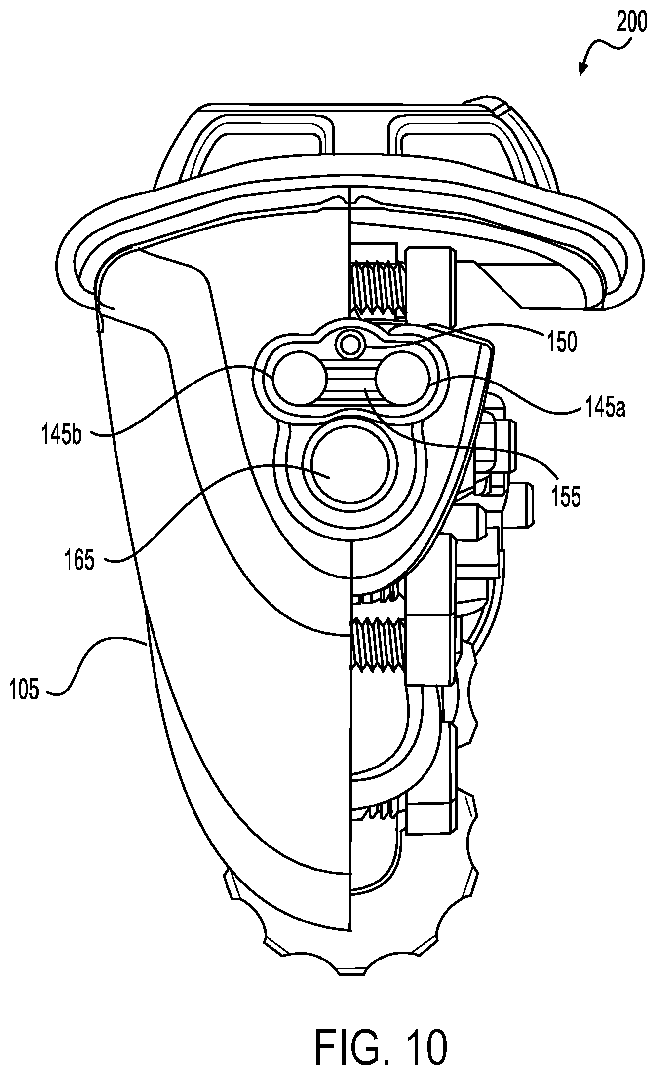
[0037] FIG. 10 illustrates a partial sectional plan front (distal) view of one aspect of the electrosurgical device depicted in FIG. 1.
[0038] FIG. 11 illustrates a perspective view of one aspect of the interior components of the electrosurgical device depicted in FIG. 1.
[0039] FIGS. 12, 13, and 14 illustrate plan views of the top, side, and bottom, respectively, of one aspect of the interior components of the electrosurgical device depicted in FIG. 11.
[0040] FIG. 15 illustrates a plan front (distal) view of one aspect of the interior components of the electrosurgical device depicted in FIG. 11.
[0041] FIG. 16 illustrates a plan rear (proximal) view of one aspect of the interior components of the electrosurgical device depicted in FIG. 11.
[0042] FIG. 17 illustrates an additional perspective view of one aspect of the interior components of the electrosurgical device depicted in FIG. 1.
[0043] FIG. 18 illustrates an expanded perspective view of one aspect of an end effector of the electrosurgical device depicted in FIG. 17.
[0044] FIG. 19 illustrates an expanded perspective view of one aspect of activation controls of the electrosurgical device depicted in FIG. 17.
[0045] FIG. 20 illustrates a front (distal) perspective view of one aspect of the electrosurgical device depicted in FIG. 17.
[0046] FIG. 21 illustrates a rear (proximal) perspective view of one aspect of the electrosurgical device depicted in FIG. 17.
[0047] FIG. 22 illustrates a cross-sectional view of one aspect of the electrosurgical device depicted in FIG. 9.
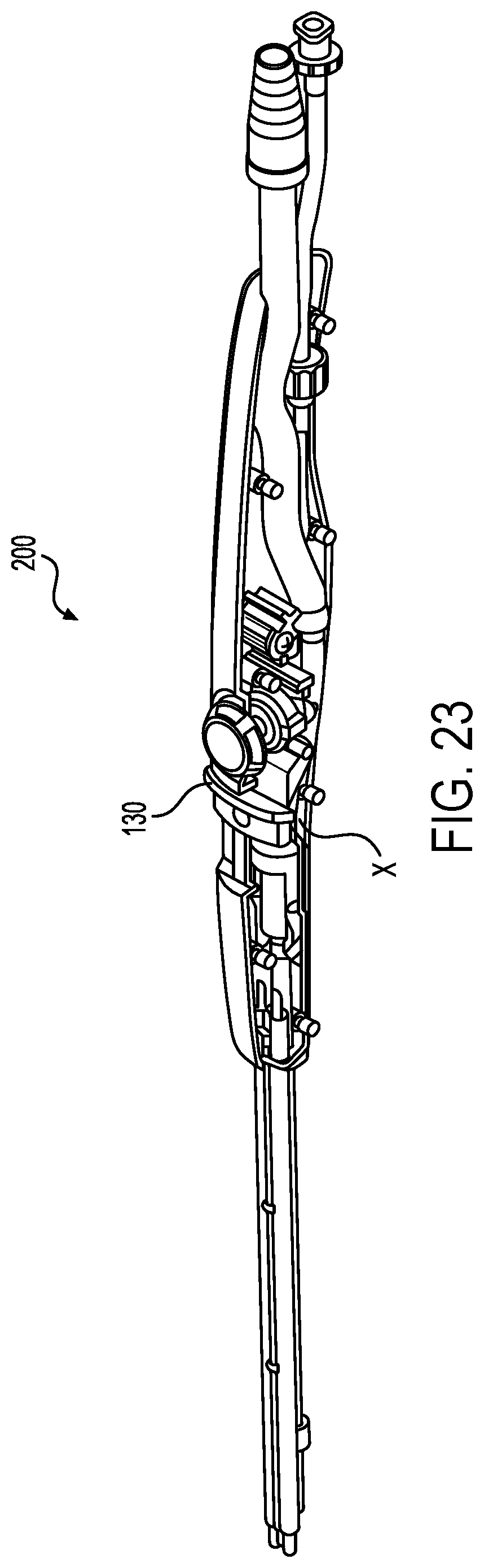
[0048] FIG. 23 illustrates partial sectional perspective view of one aspect of the electrosurgical device depicted in FIG. 9 illustrating a first position of one aspect of a slide switch.
[0049] FIG. 24 illustrates partial sectional perspective view of one aspect of the electrosurgical device depicted in FIG. 9 illustrating a second position of one aspect of a slide switch.
[0050] FIG. 25 illustrates an additional perspective view of one aspect of the interior components of the electrosurgical device depicted in FIG. 9 illustrating a second position of one aspect of a slide switch.
[0051] FIG. 26 illustrates an expanded perspective view of one aspect of an end effector of the electrosurgical device depicted in FIG. 25 illustrating an extended position of one aspect of an aspiration tube.
[0052] FIG. 27 illustrates an expanded perspective view of one aspect of activation controls of the electrosurgical device depicted in FIG. 25 illustrating a second position of one aspect of a slide switch.
[0053] FIG. 28 illustrates an expanded cross-sectional view of one aspect of a metering valve of the electrosurgical device depicted in FIG. 1.
[0054] FIGS. 29, 30, and 31 illustrate plan views of the top, side, and bottom, respectively, of one aspect of the electrosurgical device depicted in FIG. 25 illustrating a second position of one aspect of a slide switch.
[0055] FIGS. 32, 33, and 34 illustrate plan views of the top, side, and bottom, respectively, of one aspect of the electrosurgical device depicted in FIG. 9 illustrating a first position of one aspect of a slide switch.
[0056] FIG. 35 illustrates a perspective view of one aspect of an end effector of the electrosurgical device depicted in FIG. 1.
[0057] FIG. 36 illustrates a perspective view of a model of one aspect of an end effector of the electrosurgical device depicted in FIG. 1.
[0058] FIG. 37 illustrates a perspective view of a first aspect of a pair of electrodes and a diverter of an end effector of an electrosurgical device depicted in FIG. 1.
[0059] FIG. 38 illustrates a top plan view of the first aspect of a pair of electrodes and a diverter depicted in FIG. 37.
[0060] FIG. 39 illustrates a perspective view of a second aspect of a pair of electrodes and a diverter of an end effector of an electrosurgical device depicted in FIG. 1.
[0061] FIG. 40 illustrates a top plan view of the second aspect of a pair of electrodes and a diverter depicted in FIG. 39.
[0062] FIG. 41 illustrates a perspective view of a third aspect of a pair of electrodes and a diverter an end effector of an electrosurgical device depicted in FIG. 1.
[0063] FIG. 42 illustrates a top plan view of the third aspect of a pair of electrodes and a diverter depicted in FIG. 41.
[0064] FIG. 43 illustrates a perspective view of an alternate aspect of the end effector of an electrosurgical device depicted in FIG. 37.
[0065] FIG. 44 illustrates a top plan view of the alternate aspect of the end effector of an electrosurgical device depicted in FIG. 43.
[0066] FIGS. 45, 46, and 47 illustrate aspects of a fluid supply path and discharge port of an end effector of an electrosurgical device depicted in FIG. 1.
[0067] FIG. 48 illustrates a perspective view of an alternative aspect of an end effector of an electrosurgical device depicted in FIG. 1.
[0068] FIG. 49 illustrates a front (distal) plan view of the alternative aspect of the end effector depicted in FIG. 48.
[0069] FIG. 50 illustrates another aspect of the end effector of an electrosurgical device depicted in FIG. 1
DETAILED DESCRIPTION
[0070] As disclosed above, an electrosurgical device may incorporate functions to cauterize and aspirate tissues during a broad area surgical procedure. In some electrosurgical devices, energized electrodes may be used to perform the cauterization procedure. However, as also disclosed above, the electrodes of such devices may be susceptible to fouling by the tissue contacted by the electrodes during cauterization. It may be appreciated that cauterization of tissue may be accomplished by exposing the tissue to a heated material other than the electrodes. As also disclosed above, in one non-limiting example, a fluid, such as a saline fluid, may be heated by the electrodes and the heated fluid or steam may then be used to cauterize the tissue. The saline, or other conductive fluid, may be heated by an electrical current flowing between the electrodes. In this manner, the temperature used to cauterize the tissue may be limited by the temperature of the steam (for example, at around 100.degree. C.) thereby reducing the potential of tissue charring. Further, the surrounding tissue may be moistened by the steam, thereby preventing desiccation due to their proximity to a heated device. Additionally, the steam, upon losing heat by contacting the tissue, may condense to water, and the water may then be used to irrigate the surgical site. In this manner, a saline fluid may be used for the dual purposes of cauterization and irrigation, thereby increasing the efficiency of the cauterization procedure.
[0071] FIGS. 1-8 depict views of one example of such an electrosurgical device 100. For FIGS. 1-8, common reference numbers refer to common components within the figures.
[0072] The electrosurgical device 100 may include a housing 105 with a shaft 135 extending distally from the housing 105. The housing 105 may include, on a proximal end, a proximal fluid source port 115 and a proximal fluid evacuation port 110. In some electrosurgical device systems, the proximal fluid source port 115 may be placed in fluid communication with a source of a fluid, for example saline, buffered saline, Ringer's solution, or other electrically conducting fluids such as aqueous fluids containing ionic salts. The fluid source may operate as a gravity feed source or it may include components to actively pump the fluid into the proximal fluid source port 115. An actively pumping fluid source may include, without limitation, a power supply, a pump, a fluid source, and control electronics to allow a user to actively control the pumping operation of the actively pumping fluid source. In some electrosurgical device systems, the fluid evacuation port 110 may be placed in fluid communication with a vacuum source. The vacuum source may include a power supply, a pump, a storage component to store material removed by the vacuum source, and control electronics to allow a user to actively control the pumping operation of the vacuum source.
[0073] In addition, the housing 105 may include a connector 116 to which a cable 117 of an energy source 120 may be attached. The energy source 120 may be configured to supply energy (for example RF or radiofrequency energy) to the electrodes 145a,b. The energy source 120 may include a generator configured to supply power to the electrosurgical device 100 through external means, such as through the cable 117. In certain instances, the energy source 120 may include a microcontroller coupled to an external wired generator. The external generator may be powered by AC mains. The electrical and electronic circuit elements associated with the energy source 120 may be supported by a control circuit board assembly, for example. The microcontroller may generally comprise a memory and a microprocessor ("processor") operationally coupled to the memory. The electronic portion of the energy source 120 may be configured to control transmission of energy to electrodes 145a,b at the end effector 140 of the electrosurgical device 100. It should be understood that the term processor as used herein includes any suitable microprocessor, microcontroller, or other basic computing device that incorporates the functions of a computer's central processing unit (CPU) on an integrated circuit or at most a few integrated circuits. The processor may be a multipurpose, programmable device that accepts digital data as input, processes it according to instructions stored in its memory, and provides results as output. It is an example of sequential digital logic, as it has internal memory. Processors operate on numbers and symbols represented in the binary numeral system. The energy source 120 may also include input devices to allow a user to program the operation of the energy source 120.
[0074] The housing 105 may also include one or more activation devices to permit a user to control the functions of the electrosurgical device 100. In some non-limiting example, the electrosurgical device 100 may include a metering valve 125 that may be activated by a user to control an amount of fluid flowing through the electrosurgical device and provide, at the distal end, an amount of the fluid to the end effector 140. In some non-limiting examples, the metering valve 125 may also permit the user to control an amount of energy supplied by the energy source 120 to the electrodes 145a,b at the end effector 140. As an example, the metering valve 125 may comprise a screw activation pinch valve to regulate the flow of fluid through the electrosurgical device 100. Additionally, the metering valve 125 may have a push-button activation function to permit current to flow from the energy source 120 to the electrodes 145a,b upon depression of the push-button by a user. It may be recognized that in some non-limiting examples, the housing 105 may include a metering valve 125 to allow regulation of fluid flow through the electrosurgical device 100 and a separate energy control device to control the amount of current sourced to the electrodes 145a,b.
[0075] The housing 105 may also be attached to a shaft 135 at a distal end of the housing 105. An end effector 140 may be associated with a distal end of the shaft 135. The end effector 140 may include electrodes 145a,b that may be in electrical communication with the energy source 120 and may receive electrical power therefrom. In some non-limiting examples, a first electrode 145a may receive electrical energy of a first polarity (such as a positive polarity) from the energy supply 120 and the second electrode 145b may receive electrical energy of a second and opposing polarity (such as a negative polarity) from the energy supply 120. Alternatively, the first electrode 145a may be connected to a ground terminal of the energy supply 120, and the second electrode 145b may be connected to a varying AC voltage terminal of the energy supply 120. The electrodes 145a,b may extend beyond the distal end of the shaft 135. The extended ends of the electrodes 145a,b be separated by a diverter 155. The diverter 155 may contact the first electrode 145a at a first edge of the diverter 155, and the diverter 155 may contact the second electrode 145b at a second edge of the diverter 155. The diverter 155 may comprise an electrically insulating material and/or a heat resistant material, which may include, without limitation a plastic such as a polycarbonate or a ceramic. The diverter 155 may be deformable or non-deformable. In some non-limiting examples, the housing 105 may include a mechanism to control a shape of a deformable diverter 155.
[0076] The end effector 140 may also include a fluid discharge port 150 that may be in fluid communication with the fluid source port 115 through a first fluid path. The first fluid path, such as a source fluid path (see 315 in FIG. 11), may permit the fluid to flow from the fluid source port 115 to the fluid discharge port 150. In some non-limiting examples, the fluid discharge port 150 may be positioned above the diverter 155 so that a fluid emitted by the fluid discharge port 150 may be collected on a top surface of the diverter 155. The end effector may also include a fluid aspiration port 165 that may be in fluid communication with the fluid evacuation port 110 through a second fluid path. The second fluid path, such as an aspirated fluid path (see 210 in FIG. 9), may permit a liquid mixture generated at the surgical site to flow from the fluid aspiration port 165 to the fluid evacuation port 110. The liquid mixture may then be removed from the electrosurgical device 100 by the vacuum source and stored in the storage component for later removal.
[0077] In some non-limiting examples, the fluid aspiration port 165 may be formed at the distal end of an aspiration tube 160. The aspiration tube 160 may also form part of the aspirated fluid path 210. The aspiration tube 160 may be located within the shaft 135 or it may be located outside of and beneath the shaft 135. An aspiration tube 160 located outside of the shaft 135 may be in physical communication with an external surface of the shaft 135. In some examples, the aspiration tube 160 may have a fixed location with respect to the shaft 135. In some alternative examples, the aspiration tube 160 may be extendable in a distal direction with respect to the shaft 135. Extension of the extendable aspiration tube 160 may be controlled by means of an aspiration tube control device. As one non-limiting example, the aspiration tube control device may comprise a slide switch 130. The slide switch 130, in a first position (for example, in a proximal position), may cause the aspiration tube 160 to remain in a first or retracted position in which the aspiration port 165 is located essentially below the fluid discharge port 150. However, the slide switch 130 in a second position (for example in a distal position), may cause the aspiration tube 160 to extend in a distal direction to a fully extended position so that the aspiration port 165 is located distal from and beneath the fluid discharge port 150. In one example, the slide switch 130 may preferentially position the aspiration tube 160 in one of two positions, such as the retracted position and the fully extended position. It may be recognized, however, that the slide switch 130 may also permit the aspiration tube 160 to assume any position between the retracted position and the fully extended position. Regardless of the position of the aspiration tube 160 as disclosed above, the aspiration port 165 may be maintained at a location beneath a plane defined by the top surface of the diverter 155. In this manner, the diverter 155 is configured to prevent fluid emitted by the fluid discharge port 150 from directly being removed at the aspiration port 165.
[0078] FIGS. 9 and 10 present partial interior views of an electrosurgical device 200. In addition to the components disclosed above with respect to FIGS. 1-8, the electrosurgical device 200 includes an aspirated fluid path 210 that forms a fluid connection between the proximal fluid evacuation port 110 and the distal fluid aspiration port 165. Also illustrated are valve components 225 of the metering valve 125 and control components 230 of the aspiration tube such as, for example, a slide switch 130. Fluid discharge port 150, electrodes 145a,b, fluid aspiration port 165, and a portion of housing 105 are also illustrated in FIGS. 9 and 10.
[0079] FIGS. 11-21 present a variety of views of the interior components of electrosurgical device 300. FIG. 18 is a close-up view of the distal end of the electrosurgical device 300 shown in FIG. 17, and FIG. 19 is a close-up view of actuator components of the electrosurgical device 300 shown in FIG. 17 depicting the metering valve 125 and slide switch 130. Additional components depicted in FIGS. 11-21 include the source fluid path 315 that forms a fluid connection between the proximal fluid source port 115 and the distal fluid discharge port 150. In some examples, the valve components 225 of the metering valve 125 are disposed along the length of the source fluid path 315 permitting a user of electrosurgical device 300 to regulate a flow of fluid through the source fluid path 315 from the fluid source port 115 to the fluid discharge port 150. In some examples of the valve components 225, a screw actuator, such as a pinch valve, may be used to compress a portion of the source fluid path 315, thereby restricting a flow of fluid therethrough. It may be recognized that any number of fluid control valves may be used as valve components 225 including, without limitation, a ball valve, a butterfly valve, a choke valve, a needle valve, and a gate valve. It may be understood from FIGS. 11-21 that source fluid path 315 extends from fluid source port 115 through the housing 105 and through shaft 135 to the distal fluid discharge port 150. Similarly, it may be understood from FIGS. 11-22 that aspirated fluid path 210 extends form the proximal fluid evacuation port 110 through the housing 105 and through shaft 135 to the distal fluid aspiration port 165. Additionally, electrodes 145a,b may extend from housing 105 through shaft 135 and extend distally and protrude from the end of shaft 135. Alternatively, electrodes 145a,b may extend only through the shaft 135 and extend distally and protrude from the end of shaft 135. Proximal ends 345a,b of the electrodes 145a,b, may receive connectors to place the electrodes 145a,b in electrical communication with energy source 120. Electrodes 145a,b may receive the electrical energy from the energy source 120 to permit cauterization to the tissue in the surgical site either through direct contact of the tissue with the protruding portion of the electrodes 145a,b, or through heating a fluid contacting electrodes 145a,b.
[0080] FIG. 22 is a cross-sectional view of electrosurgical device 400. In particular, the cross-sectional view 400 illustrates the two fluid paths through the device. Thus, FIG. 22 illustrates source fluid path 315 in fluid communication with the proximal fluid source port 115 and the distal fluid discharge port 150. Additionally, FIG. 22 illustrates an example of a physical relationship between source fluid path 315 and the valve components 225 of the metering valve 125. FIG. 22 also illustrates an example in which the source fluid path 315 may extend through both the housing 105 and the shaft 135. Further, FIG. 22 illustrates aspirated fluid path 210 in fluid communication with the proximal fluid evacuation port 110 and the distal fluid aspiration port 165. The aspirated fluid path 210 may also include an aspiration tube 160 that may be disposed at a distal end of the aspirated fluid path 210. The distal fluid aspiration port 165 may be formed at a distal end of the aspiration tube 160.
[0081] FIGS. 23-27 and 29-34 illustrate partial interior views of an electrosurgical device 200 having an aspiration tube 160 in a proximal or retracted position and an electrosurgical device 500 having an aspiration tube 160 in an distal or extended position Z. FIG. 23 is similar to FIG. 9 and particularly illustrates a first and proximal position X of the slide switch 130 (as a non-limiting example of an aspiration tube control device) along with a proximal or retracted position of aspiration tube 160. FIG. 24 particularly illustrates a second and distal position Y of the slide switch 130 (as a non-limiting example of an aspiration tube control device) in addition to a distal or extended position Z of aspiration tube 160. FIG. 25 illustrates an alternative perspective view of electrosurgical device 500. FIG. 26 is an expanded perspective view of the distal end of the electrosurgical device 500 shown in FIG. 25, particularly illustrating the distal end of aspiration tube 160 in the extended position Z. FIG. 27 is an expanded perspective view of actuator components of the electrosurgical device 500 shown in FIG. 25, particularly illustrating the second or distal position X of the slide switch 130. FIGS. 29, 30, and 31 present plan views of the top, side, and bottom, respectively, of electrosurgical device 500. FIGS. 29-31 may be compared with FIGS. 32, 33, and 34 which present plan views of the top, side, and bottom, respectively, of electrosurgical device 200. FIGS. 29-31 illustrate the distal positions Y and Z of slide switch 130 and aspiration tube 160, respectively. FIGS. 32-34 illustrate the proximal position X of slide switch 130 and the proximal or retracted position of aspiration tube 160.
[0082] FIG. 28 illustrates a cross sectional view of an example of a metering valve 125 depicting some exemplary metering valve components 225. The valve components 225 may include a switch button 525 that may be activated by a user. The valve components 225 may also include an adjustable stop mechanism 527 that may adjust the position of a pinch valve 532 with respect to a portion of the source fluid path 315. The adjustable stop mechanism 527 may comprise a screw activated portion that may be adjusted by a rotation of the switch button 525. In this manner, a user may rotate the switch button 525 and adjust an amount of fluid flowing through the source fluid path 315 to exit from the distal fluid discharge port 150 based on an amount of compression applied to source fluid path 315 by a pinch valve. In some examples, the adjustable stop mechanism 527 may have two positions (an "open" position and a "closed" position). Alternatively, the adjustable stop mechanism 527 may be adjustable and permit the user to select any amount of fluid flow through the source fluid path 315.
[0083] Additionally, the metering valve 125 may include additional components 225 that may be used to control an electrical connection between the electrodes 145a,b and the energy source 120. For example, an RF switch 530 may used to form the electrical connections between the electrodes 145a,b and the energy source 120. In one example, the RF switch 530 may be a momentary contact switch that connects the electrodes 145a,b and the energy source 120 only when actively depressed by a user. Alternatively, the RF switch 530 may be a latching push button switch that may be sequentially activated (push-to-make) and deactivated (push-to-break) upon being depressed. A closure spring 534 may be included among the switch components 225 to return the switch button 525 to an undepressed state when a user is not actively depressing the switch button 525.
[0084] FIG. 35 presents a perspective view of a general example of an end effector 600. As disclosed above, the end effector may be composed of a pair of electrodes 145a,b, extending from a shaft 135, a distal fluid discharge port 150, a diverter 155, and an aspiration port 165 that may be part of an aspiration tube 160. The diverter 155 may be placed between the pair of electrodes 145a,b in such a manner as to form a contact of a first edge of the diverter 155 with a surface of one electrode 145a, and a contact of a second edge of the diverter 155 with a surface on a second electrode 145b. In some examples, a proximal edge of the diverter 155 may form a mechanical communication with an end surface of the shaft 135. In this manner, fluid emitted by the distal fluid discharge port 150 may be retained on a first or top surface of the diverter 155. The fluid on the top surface of the diverter 155 may be retained on that surface for a sufficient time to maintain contact of the fluid with a surface of both electrodes 145a,b. If the fluid is an ionic fluid, current passing through the fluid between the electrodes 145a,b may heat the fluid sufficiently to form a steam capable of cauterizing tissue.
[0085] FIG. 36 depicts a perspective view of a fabricated model of the end effector 600 as depicted in FIG. 35.
[0086] FIGS. 37-44 depict a variety of examples of an end effector as generally disclosed as end effector 600 depicted in FIG. 35.
[0087] FIGS. 37 and 38 illustrate a perspective view and a top plan view, respectively, of one example of end effector 700. End effector 700 illustrates many of the components disclosed above with respect to end effector 600 of FIG. 36. These components include the shaft 135, the fluid discharge port 150, the aspirator port 165, the electrodes 145a,b, and aspirator tube 160. In addition to the aspirator port 165, the aspirator tube 160 may include additional ports along the length of the aspirator tube 160 to aspirate material from the surgical site. The diverter 755 of end effector 700 includes a number of features 757a configured to direct the flow of a fluid emitted by fluid discharge port 150 to the surface of electrodes 145a,b. Features 757a may include curved guide-ways protruding from the top surface of the diverter 755. Additionally, the top surface of the diverter 755 may include additional features at the distal end to further guide the fluid towards the electrodes 145a,b. The electrodes 145a,b may have a generally circular or elliptical cross section 745a,b at a portion near the distal end of the shaft 135. Further, the electrodes 145a,b may be chamfered at their distal ends 747a,b resulting in an oval or egg-shaped distal end 747a,b. Cross-sectional view F in FIG. 38 illustrates that the oval distal ends 747a,b of the electrodes 145a,b have their respective long axes directed to the outer portion of the end effector 700, away from the diverter 755.
[0088] FIGS. 39 and 40 illustrate a perspective view and a top plan view, respectively, of another example of end effector 700. In FIGS. 39 and 40, the distal portion of the electrodes 145a,b may have a circular or oval cross section, but the electrodes 145a,b may have a fabiform or kidney-shaped cross section 745c,d closer (proximal) to the shaft 135. Such a fabiform cross section 745c,d may be useful during fabrication of the electrosurgical device to secure the diverter 755 between the inner surfaces of the electrodes 145a,b. Cross sectional view G of FIG. 40 illustrates how the diverter 755 may be secured against the inner surfaces of the fabiform cross section 745c,d. The example of end effector 700 depicted in FIGS. 39 and 40 also are distinguished from that depicted in FIGS. 37 and 38 in that the features 757b comprising the protruding fluid guide-ways comprise straight guide-ways to direct the fluid on the top surface of the diverter 755 to the electrodes 145a,b. Additionally, the electrodes 145a,b may be chamfered to result in oval distal ends 747c,d in which the respective long axes 749a,b are directed towards the inner portion of the end effector 700, and pointing towards the diverter 755. This geometry is depicted in FIG. 40, cross-sectional view H.
[0089] FIGS. 41 and 42 illustrate a perspective view and a top plan view, respectively, of yet another example of end effector 700. The end effector 700 depicted in FIGS. 41 and 42 shows common elements to those of examples illustrated in FIGS. 37-40. Thus, the electrodes 145a,b have a circular or elliptical cross section 745a,b as illustrated in FIGS. 37 and 38 but include the oval cross sections 747c,d at the distal ends of the electrodes 145a,b as depicted in FIGS. 39 and 40. The fluid flow features 757c illustrated in FIGS. 41 and 42 are fabricated as recesses in the surface of the diverter 756. Such recess features 757c may form channels that may be used to guide the flow of a fluid on the top surface of the diverter 756 as suggested by the arrows shown in FIG. 42. The recess figures 757c may also specifically guide a flow of the fluid against the inner surfaces of electrodes 145a,b as also illustrated in FIG. 42. The features 757c may also include a spill-way to direct the fluid emitted by the fluid discharge port 150 towards the channels in the surface of diverter 756 thereby preventing the fluid from flowing out of the recesses when the fluid initially leaves the fluid discharge port 150.
[0090] FIGS. 43 and 44 illustrate a perspective view and a top plan view, respectively, of still another example of end effector 700. The electrodes 145a,b, shaft 135, the fluid discharge port 150, the aspirator port 165, and aspirator tube 160 are all similar to the examples depicted in FIG. 37. Additionally, a portion of the source fluid path 315 proximal to the fluid discharge port 150 may include features such as rifling 750 on the inner surface of the source fluid path 315. Such rifling 750 may impart a turbulent flow to a fluid emitted by the fluid discharge port 150, especially if the fluid is sourced under pressure. Thus, a fluid entering the distal end of source fluid path 315 (arrow on right of FIG. 44) may exit at the fluid discharge port 150 having a turbulent flow that is more easily distributed by the features 757a on the top surface of diverter 755, as illustrated by the arrows superimposed on the top surface of diverter 755 in FIG. 44. As a result, the fluid on the top surface of diverter 755 may more readily flow to contact the electrodes 145a,b.
[0091] The flow of a fluid emitted by fluid discharge port 150 may also be varied by the incorporation of apertures at the distal end of the fluid discharge port 150. FIGS. 45, 46, and 47 illustrate, respectively, fluid flow through a slit aperture 850a, a circular or pinhole aperture 850b, and a semi-lunar aperture 850c. The rifling 750 may be added to a source fluid path 315 terminating in a fluid discharge port 150 having any of the apertures 850a-c as illustrated in FIGS. 45-47. FIG. 46, for example, depicts the rifling 750 used in addition to a circular or pinhole aperture 850b.
[0092] FIGS. 48 and 49 illustrate a perspective view and a vertical cross sectional view, respectively, of an example of end effector 800 that comprises three electrodes. The end effector 800 depicted in FIGS. 48 and 49 includes, as disclosed in examples depicted in FIGS. 37-44, a distal end of a shaft 135, a fluid discharge port 150, and an aspirator port 165. Also depicted in FIGS. 48 and 49 are a pair of electrodes 145a,b that are disposed juxtaposed to each other and are separated by a diverter 855. The diverter 855 illustrated in FIGS. 48 and 49 may include a series of protruding feature 857 that may differ from those in examples depicted in FIGS. 37-40. In the example of end effector 800 illustrated by FIGS. 48 and 49, a third electrode 845 may be incorporated on the top surface of the diverter 855. In the examples of end effectors illustrated above, the two electrodes 145a,b are disposed juxtaposed to each having a spacing between them. As disclosed above, a first electrode 145a may receive electrical energy of a first polarity (such as a positive polarity) from the energy supply 120 and the second electrode 145b may receive electrical energy of a second and opposing polarity (such as a negative polarity) from the energy supply 120. Alternatively, the first electrode 145a may be connected to a ground terminal of the energy supply 120, and the second electrode 145b may be connected to a varying AC voltage terminal of the energy supply 120. The electrodes 145a,b illustrated in FIGS. 48 and 49 may receive electrical energy having the same polarity while additional electrode 845 may receive electrical energy having a second and opposing polarity. Alternatively, electrodes 145a,b may be connected to a varying AC voltage terminal of the energy supply 120 while the third electrode 845 may be connected to a ground terminal of the energy supply 120. In yet another alternative example, electrodes 145a,b may be connected to a ground terminal of the energy supply 120 while the third electrode 845 may be connected to a varying AC voltage terminal of the energy supply 120. It may be understood that an end effector may include any number of electrodes disposed in any appropriate geometry around or about a diverter placed therebetween or thereamong.
[0093] FIG. 50 illustrates an alternative example of an end effector 900. End effector 900 includes a pair of electrodes 945a,b that have a fabiform or kidney-shaped cross section. Diverter 955 is positioned between the concave inner surfaces of electrodes 945a,b, and an aspirator tube having a distal aspiration port 965 is positioned below the diverter 955. Unlike many of the end effectors disclosed above, the source fluid path 315 in end effector 900 does not terminate in a discharge port 150 at a distal end of the shaft 135. Instead, as illustrated in FIG. 50, the source fluid path 315 may continue along the length of one or more of the electrodes. For example, the source fluid path 315 may extend as one or more cannulae 915a,b that are positioned, for example, along the inner concave surface of the electrodes 945a,b. The cannulae 915a,b may be placed against or in proximity to the top surface of the diverter 955. The cannulae 915a,b may also include pores or weep-holes 950 that may permit a fluid flowing through the source fluid path 315 and the cannulae 915a,b, to flow onto the top surface of the diverter 955. The fluid may flow from the pores or weep-holes 950 onto the top surface of the diverter 955 due to capillary action and/or surface tension. Although two cannulae 915a,b, are illustrated in FIG. 50, it may be understood that a single cannula or multiple cannulae may be used to provide the fluid to flow onto the top surface of the diverter 955.
[0094] It will be appreciated that the terms "proximal" and "distal" are used throughout the specification with reference to a clinician manipulating one end of an instrument used to treat a patient. The term "proximal" refers to the portion of the instrument closest to the clinician and the term "distal" refers to the portion located furthest from the clinician. It will further be appreciated that for conciseness and clarity, spatial terms such as "vertical," "horizontal," "up," or "down" may be used herein with respect to the illustrated embodiments. However, surgical instruments may be used in many orientations and positions, and these terms are not intended to be limiting or absolute.
[0095] Various aspects of surgical instruments are described herein. It will be understood by those skilled in the art that the various aspects described herein may be used with the described surgical instruments. The descriptions are provided for example only, and those skilled in the art will understand that the disclosed examples are not limited to only the devices disclosed herein, but may be used with any compatible surgical instrument or robotic surgical system.
[0096] Reference throughout the specification to "various aspects," "some aspects," "one example," or "one aspect" means that a particular feature, structure, or characteristic described in connection with the aspect is included in at least one example. Thus, appearances of the phrases "in various aspects," "in some aspects," "in one example," or "in one aspect" in places throughout the specification are not necessarily all referring to the same aspect. Furthermore, the particular features, structures, or characteristics illustrated or described in connection with one example may be combined, in whole or in part, with features, structures, or characteristics of one or more other aspects without limitation.
[0097] While various aspects herein have been illustrated by description of several aspects and while the illustrative embodiments have been described in considerable detail, it is not the intention of the applicant to restrict or in any way limit the scope of the appended claims to such detail. Additional advantages and modifications may readily appear to those skilled in the art. For example, it is generally accepted that endoscopic procedures are more common than laparoscopic procedures. Accordingly, the present invention has been discussed in terms of endoscopic procedures and apparatus. However, use herein of terms such as "endoscopic", should not be construed to limit the present invention to an instrument for use only in conjunction with an endoscopic tube (e.g., trocar). On the contrary, it is believed that the present invention may find use in any procedure where access is limited to a small incision, including but not limited to laparoscopic procedures, as well as open procedures.
[0098] It is to be understood that at least some of the figures and descriptions herein have been simplified to illustrate elements that are relevant for a clear understanding of the disclosure, while eliminating, for purposes of clarity, other elements. Those of ordinary skill in the art will recognize, however, that these and other elements may be desirable. However, because such elements are well known in the art, and because they do not facilitate a better understanding of the disclosure, a discussion of such elements is not provided herein.
[0099] While several aspects have been described, it should be apparent, however, that various modifications, alterations and adaptations to those embodiments may occur to persons skilled in the art with the attainment of some or all of the advantages of the disclosure. For example, according to various aspects, a single component may be replaced by multiple components, and multiple components may be replaced by a single component, to perform a given function or functions. This application is therefore intended to cover all such modifications, alterations and adaptations without departing from the scope and spirit of the disclosure as defined by the appended claims.
[0100] Any patent, publication, or other disclosure material, in whole or in part, that is said to be incorporated by reference herein is incorporated herein only to the extent that the incorporated materials does not conflict with existing definitions, statements, or other disclosure material set forth in this disclosure. As such, and to the extent necessary, the disclosure as explicitly set forth herein supersedes any conflicting material incorporated herein by reference. Any material, or portion thereof, that is said to be incorporated by reference herein, but which conflicts with existing definitions, statements, or other disclosure material set forth herein will only be incorporated to the extent that no conflict arises between that incorporated material and the existing disclosure material.
[0101] Various aspects of the subject matter described herein are set out in the following numbered examples:
Example 1
[0102] An electrosurgical device comprising: a proximal fluid source port and a first fluid path in fluid communication with the proximal fluid source port; a proximal fluid evacuation port and a second fluid path in fluid communication with the proximal fluid evacuation port; a first electrode and a second electrode; a housing configured to enclose a first portion of the first fluid path, a first portion of the second fluid path, a first portion of the first electrode, and a first portion of the second electrode; a shaft extending distally from the housing configured to enclose a second portion of the first fluid path, a second portion of the second fluid path, a second portion of the first electrode, and a second portion of the second electrode and an end effector, the end effector comprising: a distal fluid discharge port in fluid communication with the second portion of the first fluid path; a distal fluid aspiration port in fluid communication with the second portion of the second fluid path; a third portion of the first electrode and a third portion of the second electrode; and a diverter comprising a first surface, a first edge in mechanical communication with the third portion of the first electrode and a second edge in mechanical communication with the third portion of the second electrode.
Example 2
[0103] The electrosurgical device of Example 1, wherein the diverter is configured to maintain a contact between the fluid, a surface of the third portion of the first electrode, and a surface of the third portion of the second electrode.
Example 3
[0104] The electrosurgical device of Example 1, wherein the diverter comprises a plurality of features on the first surface.
Example 4
[0105] The electrosurgical device of Example 3, wherein the plurality of features are configured to direct a fluid flow of the fluid on the first surface of the diverter.
Example 5
[0106] The electrosurgical device of Example 3, wherein the plurality of features comprise a plurality of protrusions.
Example 6
[0107] The electrosurgical device of Example 3, wherein the plurality of features comprise a plurality of recesses.
Example 7
[0108] The electrosurgical device of Example 1, wherein the distal fluid discharge port comprises an aperture comprising a circular opening, a semi-lunar opening, or a slit opening.
Example 8
[0109] The electrosurgical device of Example 1, wherein the second portion of the first fluid path proximal to the distal fluid discharge port is configured to impart a turbulent flow to a fluid flowing therethrough.
Example 9
[0110] The electrosurgical device of Example 1, wherein the second portion of the first fluid path comprises a first cannula and a second cannula.
Example 10
[0111] The electrosurgical device of Example 9, wherein the first cannula is in mechanical communication with an inner surface of the third portion of the first electrode and the second cannula is in mechanical communication with an inner surface of the third portion of the second electrode.
Example 11
[0112] The electrosurgical device of Example 9, wherein the distal fluid discharge port comprises a plurality of pores in the first cannula and the second cannula.
Example 12
[0113] An end effector of an electrosurgical device, the end effector comprising: a distal fluid discharge port in fluid communication with a first fluid path; a distal fluid aspiration port in fluid communication with a second fluid path; a first electrode and a second electrode; and a diverter in mechanical communication with the first electrode and the second electrode, and disposed therebetween, wherein the diverter is configured to receive, on a first surface, a fluid emitted by the distal fluid discharge port, and to maintain a contact of the fluid thereon with a surface of the first electrode and a surface of the second electrode, and wherein the diverter is configured to prevent an aspiration by the distal fluid aspiration port of the fluid on the first surface thereof.
Example 13
[0114] The end effector of Example 12, wherein the diverter comprises an electrically insulating material.
Example 14
[0115] The end effector of Example 12, wherein the diverter comprises a heat resistant material.
Example 15
[0116] The end effector of Example 12, wherein the diverter comprises a plurality of features on the first surface.
Example 16
[0117] The end effector of Example 15, wherein the plurality of features are configured to direct a flow of the fluid on the first surface of the diverter towards the first electrode or the second electrode.
Example 17
[0118] The end effector of Example 15, wherein the plurality of features comprise a plurality of protrusions.
Example 18
[0119] The end effector of Example 15, wherein the plurality of features comprise a plurality of recesses.
Example 19
[0120] The end effector of Example 12, wherein the first fluid path comprises a first cannula and a second cannula.
Example 20
[0121] The end effector of Example 19, wherein the first cannula is in mechanical communication with an inner surface of the first electrode and the second cannula is in mechanical communication with an inner surface of the second electrode.
Example 21
[0122] The end effector of Example 19, wherein the distal fluid discharge port comprises a plurality of pores in the first cannula and the second cannula and wherein the plurality of pores are configured to source the fluid onto the first surface of the diverter.
Example 22
[0123] An end effector of an electrosurgical device, the end effector comprising: an outlet port in fluid communication with a first fluid path; an inlet port in fluid communication a second fluid path; a first electrode and a second electrode positioned in juxtaposed relationship; and a diverter comprising a first surface configured to receive fluid emitted by the outlet port, wherein the diverter is disposed between the first and second juxtaposed electrodes, and wherein the diverter is disposed between the outlet port and the inlet port to separate the outlet port and the inlet port.
Example 23
[0124] The electrosurgical device of Example 1, wherein the diverter is configured to receive, on the first surface, a fluid emitted by the distal fluid discharge port.
Example 24
[0125] The electrosurgical device of Example 1, wherein the distal fluid aspiration port is configured to remove a material from an area proximal to the diverter.
* * * * *
D00000
D00001
D00002
D00003
D00004
D00005
D00006
D00007
D00008
D00009
D00010
D00011
D00012

D00013

D00014
D00015

D00016

D00017

D00018

D00019

D00020

D00021

D00022

D00023

D00024

D00025

D00026

D00027

D00028

XML
uspto.report is an independent third-party trademark research tool that is not affiliated, endorsed, or sponsored by the United States Patent and Trademark Office (USPTO) or any other governmental organization. The information provided by uspto.report is based on publicly available data at the time of writing and is intended for informational purposes only.
While we strive to provide accurate and up-to-date information, we do not guarantee the accuracy, completeness, reliability, or suitability of the information displayed on this site. The use of this site is at your own risk. Any reliance you place on such information is therefore strictly at your own risk.
All official trademark data, including owner information, should be verified by visiting the official USPTO website at www.uspto.gov. This site is not intended to replace professional legal advice and should not be used as a substitute for consulting with a legal professional who is knowledgeable about trademark law.