Articulatable Surgical Stapling Instruments
Shelton, IV; Frederick E. ; et al.
U.S. patent application number 16/898693 was filed with the patent office on 2020-12-03 for articulatable surgical stapling instruments. The applicant listed for this patent is Ethicon LLC. Invention is credited to Chester O. Baxter, III, Jason L. Harris, Frederick E. Shelton, IV.
| Application Number | 20200375597 16/898693 |
| Document ID | / |
| Family ID | 1000005019600 |
| Filed Date | 2020-12-03 |


View All Diagrams
| United States Patent Application | 20200375597 |
| Kind Code | A1 |
| Shelton, IV; Frederick E. ; et al. | December 3, 2020 |
ARTICULATABLE SURGICAL STAPLING INSTRUMENTS
Abstract
A surgical instrument that includes a shaft assembly that defines a shaft axis and includes a proximal articulation joint that defines a first articulation axis that is transverse to the shaft axis and a distal articulation joint that defines a second articulation axis that is transverse to the shaft axis and the first articulation axis. The instrument further includes an anvil that is non-removably attached to the shaft assembly and a channel that is removably attachable to the shaft assembly and configured to operably support a surgical staple cartridge.
| Inventors: | Shelton, IV; Frederick E.; (Hillsboro, OH) ; Baxter, III; Chester O.; (Loveland, OH) ; Harris; Jason L.; (Lebanon, OH) | ||||||||||
| Applicant: |
|
||||||||||
|---|---|---|---|---|---|---|---|---|---|---|---|
| Family ID: | 1000005019600 | ||||||||||
| Appl. No.: | 16/898693 | ||||||||||
| Filed: | June 11, 2020 |
Related U.S. Patent Documents
| Application Number | Filing Date | Patent Number | ||
|---|---|---|---|---|
| 15386230 | Dec 21, 2016 | |||
| 16898693 | ||||
| Current U.S. Class: | 1/1 |
| Current CPC Class: | A61B 2017/07257 20130101; A61B 2017/07242 20130101; A61B 2017/00685 20130101; A61B 2017/00039 20130101; A61B 2017/0725 20130101; A61B 2017/2931 20130101; A61B 90/03 20160201; A61B 2017/00477 20130101; A61B 2017/00464 20130101; A61B 2090/065 20160201; A61B 17/07207 20130101; A61B 2017/07278 20130101; A61B 2017/00017 20130101; A61B 34/30 20160201; A61B 2017/00398 20130101; A61B 2017/07271 20130101; A61B 2017/00964 20130101; A61B 2090/0814 20160201; A61B 2017/2927 20130101; A61B 2017/2933 20130101; A61B 2017/00734 20130101; A61B 2090/08021 20160201; A61B 2017/07264 20130101; A61B 17/0682 20130101; A61B 2017/00473 20130101; A61B 2017/0046 20130101; A61B 2017/00309 20130101; A61B 2017/07285 20130101; A61B 2090/0811 20160201; A61B 2017/07228 20130101; A61B 2017/07214 20130101; A61B 2017/2929 20130101; A61B 2017/07221 20130101; A61B 2090/034 20160201; A61B 2090/0801 20160201 |
| International Class: | A61B 17/072 20060101 A61B017/072; A61B 17/068 20060101 A61B017/068; A61B 34/30 20060101 A61B034/30; A61B 90/00 20060101 A61B090/00 |
Claims
1. A surgical instrument, comprising: a shaft assembly defining a shaft axis and comprising: a proximal articulation joint defining a first articulation axis that is transverse to said shaft axis; a distal articulation joint defining a second articulation axis that is transverse to said shaft axis and said first articulation axis; a drive shaft configured to transmit rotary drive motions from a source of rotary drive motions; and a movable anvil and wherein said surgical instrument further comprises: a channel that is configured to operably support a surgical staple cartridge therein, said channel being configured to be removably attached to said shaft assembly, and a firing member movably supported in said channel and configured to operably interface with said drive shaft when said channel is operably coupled to said shaft assembly, said firing member operably movable between a first proximal position wherein said firing member applies an opening motion to said anvil and closing positions wherein said firing member applies closing motions to said anvil.
2. The surgical instrument of claim 1, wherein said channel is configured to be attached to said shaft assembly in an installation direction that is transverse to said shaft axis.
3. The surgical instrument of claim 1, wherein said shaft assembly further comprises a spine member and wherein said proximal articulation joint comprises a first channel mounting assembly pivotally coupled to said spine member for selective articulation relative thereto about said first articulation axis and wherein said distal articulation joint comprises a second channel mounting member pivotally coupled to said first channel mounting assembly for selective pivotal travel relative to said first channel mounting assembly about said second articulation axis.
4. The surgical instrument of claim 3, further comprising: a first articulation system operably interfacing with said first channel mounting assembly for selectively applying first articulation motions thereto; and a second articulation system operably interfacing with said second channel mounting member for selectively applying second articulation motions thereto.
5. The surgical instrument of claim 4, wherein said first articulation system comprises a first axially movable articulation actuator operably coupled to said first channel mounting assembly and wherein said second articulation system comprises: a second endless articulation member operably interfacing with said second channel mounting member and configured to apply said second articulation motions thereto as said second endless articulation member is rotated; and means for rotating said second articulation member.
6. The surgical instrument of claim 5, wherein said means for rotating comprises a second axially movable articulation actuator operably interfacing with said second endless articulation member.
7. The surgical instrument of claim 3, wherein portions of said channel are configured to be slidably received within corresponding slots in said second channel mounting member.
8. The surgical instrument of claim 7, wherein said portions of said channel are configured to be slidably inserted into said corresponding slots in said second channel mounting member in an installation direction that is transverse to said shaft axis.
9. The surgical instrument of claim 8, further comprising means for releasably retaining said portions of said channel in said corresponding slots.
10. The surgical instrument of claim 9, wherein said means for releasably retaining comprises a lock member that is selectively axially movable between a locked position wherein said portions of said channel are retained within said corresponding slots and an unlocked position wherein said portions of said channel are removable from said corresponding slots in a removal direction that is opposite to said installation direction.
11. The surgical instrument of claim 10, wherein said lock member is axially movable in locking directions that are transverse to said installation directions and said removal directions.
12. A surgical instrument, comprising: a shaft assembly, comprising: a spine member defining a shaft axis; a first channel mounting assembly movably coupled to said spine member for selective articulation relative thereto in a first articulation plane; a second channel mounting member movably coupled to said first channel mounting assembly for selective articulation relative thereto in a second articulation plane that is perpendicular to said first articulation plane; a flexible rotary drive shaft; and an anvil pivotally coupled to said second channel mounting member and wherein said surgical instrument further comprises: a channel that is configured to operably support a surgical staple cartridge therein, said channel configured to be removably detached from said second channel mounting member apart from said anvil, and a firing member movably supported in said channel and configured to operably interface with said flexible rotary drive shaft when said channel is operably coupled to said second channel mounting member, said firing member operably movable between a first proximal position wherein said firing member applies an opening motion to said anvil and closing positions wherein said firing member applies closing motions to said anvil.
13. The surgical instrument of claim 12, wherein said firing member comprises: a tissue cutting portion; and means for ejecting surgical staples from a surgical staple cartridge supported in said channel as said firing member is driven between said first proximal position and an ending position within said channel.
14. The surgical instrument of claim 12, wherein said channel is configured to be attached to said second channel mounting member in an installation direction that is transverse to said shaft axis.
15. The surgical instrument of claim 14, wherein said shaft assembly further comprises a lock member movably supported on said spine member and being selectively axially movable thereon between a locked position wherein said channel is locked to said second channel mounting member and an unlocked position wherein said channel is detachable from said second channel mounting member.
16. A surgical instrument, comprising: a shaft assembly, comprising: a spine assembly; and an axially movable firing bar and wherein said surgical instrument further comprises: a surgical end effector comprising: a channel configured to operably support a surgical staple cartridge therein, said channel being configured to be removably coupled to said spine assembly by a connector assembly; and a firing member supported for axial travel within a surgical staple cartridge supported within said channel, said firing member comprising a proximally protruding coupler sized to be removably inserted into a corresponding retention cavity formed in a distal end of said axially movable firing bar, said corresponding retention cavity being sized relative to said proximally protruding coupler to snappingly receive said proximally protruding coupler therein when said channel is removably coupled to said spine assembly.
17. The surgical instrument of claim 16, wherein said connector assembly comprises: a channel retainer operably coupled to said spine assembly; a distal channel coupler comprising a pair of inwardly extending, diametrically opposed attachment pins configured to be axially inserted into corresponding coupling slots in said channel retainer that are transverse to said shaft axis.
18. The surgical instrument of claim 17, wherein said spine assembly comprises a flexible articulation segment movably coupled to said channel retainer.
19. The surgical instrument of claim 18, wherein said channel retainer is movably coupled to said flexible articulation segment by at least one axially movable articulation bar that is movably supported by said flexible articulation segment.
20. The surgical instrument of claim 16, wherein said axially moving firing bar comprises a plurality of laminated plates.
Description
CROSS-REFERENCE TO RELATED APPLICATION
[0001] This application is a continuation application claiming priority under 35 U.S.C. .sctn. 120 to U.S. patent application Ser. No. 15/386,230, entitled ARTICULATABLE SURGICAL STAPLING INSTRUMENTS, filed Dec. 21, 2016, now U.S. Patent Application Publication No. 2018/0168649, the entire disclosure of which is hereby incorporated by reference herein.
BACKGROUND
[0002] The present invention relates to surgical instruments and, in various arrangements, to surgical stapling and cutting instruments and staple cartridges for use therewith that are designed to staple and cut tissue.
BRIEF DESCRIPTION OF THE DRAWINGS
[0003] Various features of the embodiments described herein, together with advantages thereof, may be understood in accordance with the following description taken in conjunction with the accompanying drawings as follows:
[0004] FIG. 1 is a perspective view of an interchangeable surgical tool assembly operably coupled to a handle assembly;
[0005] FIG. 1A is an elevation exploded assembly view of the handle assembly of FIG. 1 and a plurality of interchangeable surgical tool assemblies therefor;
[0006] FIG. 2 is a perspective exploded assembly view of the handle assembly and portions of the interchangeable surgical tool assembly of FIG. 1;
[0007] FIG. 3 is a perspective view of a distal portion of the interchangeable surgical tool assembly depicted in FIG. 1 with portions thereof omitted for clarity;
[0008] FIG. 4 is a perspective cross-sectional view of a distal portion of the interchangeable surgical tool assembly depicted in FIG. 1 taken along the longitudinal axis thereof with portions thereof omitted for clarity;
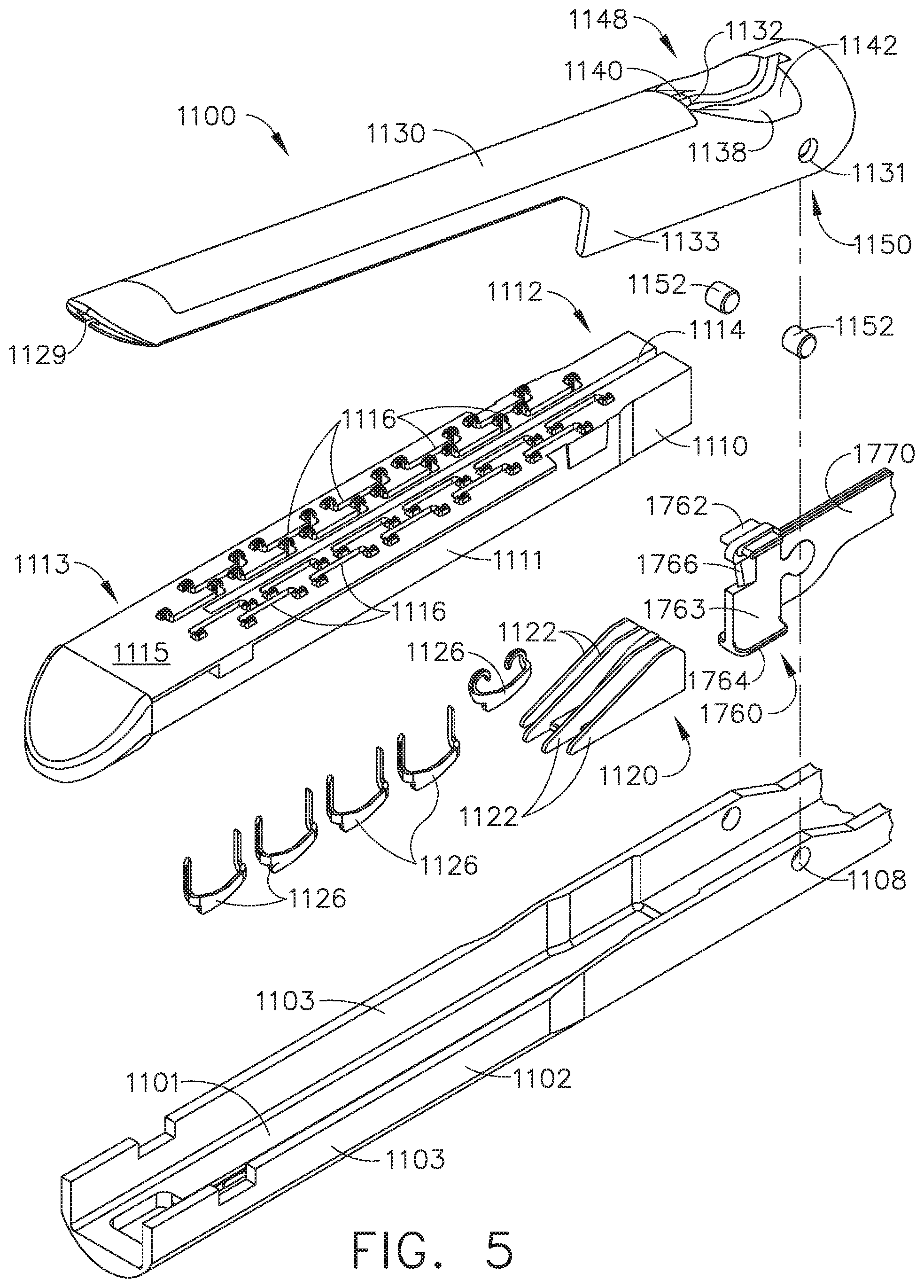
[0009] FIG. 5 is an exploded assembly view of a distal portion of the interchangeable surgical tool assembly of FIG. 1;
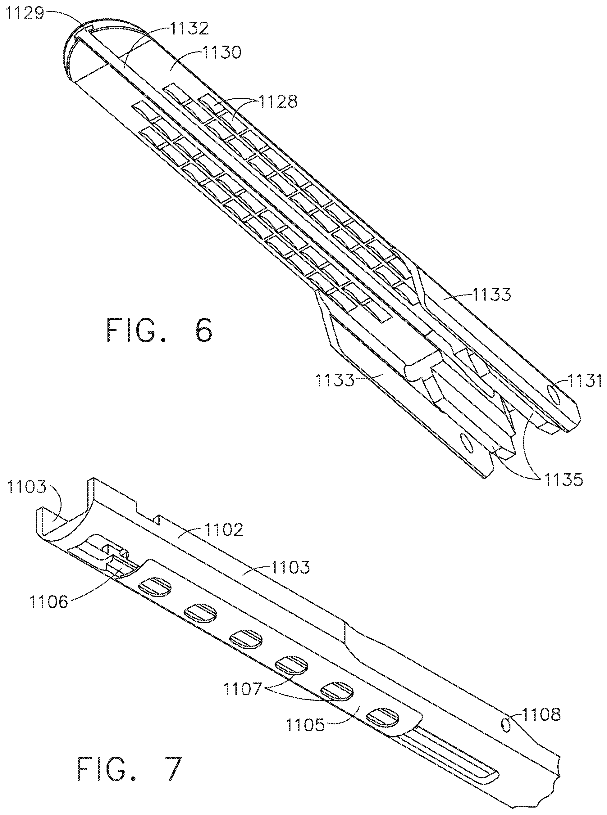
[0010] FIG. 6 is a perspective view of an anvil of the interchangeable surgical tool assembly depicted in FIG. 1;
[0011] FIG. 7 is a perspective view of an elongate channel of the interchangeable surgical tool assembly depicted in FIG. 1;
[0012] FIG. 8 is a perspective view of a pivot joint of the interchangeable surgical tool assembly of FIG. 1;
[0013] FIG. 9 is a plan view of the pivot joint of FIG. 8;
[0014] FIG. 10 is an elevation cross-sectional view of a distal portion of the interchangeable surgical tool assembly of FIG. 1 depicting a firing member at the pivot joint of FIG. 8 in an initial position;
[0015] FIG. 11 is an elevation cross-sectional view of a distal portion of the interchangeable surgical tool assembly of FIG. 1 depicting the firing member at the pivot joint of FIG. 8 in a proximally-retracted position from the initial position;
[0016] FIG. 12 is an elevation cross-sectional view of a distal portion of the interchangeable surgical tool assembly of FIG. 1 depicting the firing member at the pivot joint of FIG. 8 in a distally-advanced position from the initial position;
[0017] FIG. 13 is a perspective view of a distal portion of an interchangeable surgical tool assembly depicting a distal nose portion thereof in an initial configuration;
[0018] FIG. 14 is an elevation view of a distal portion of the interchangeable surgical tool assembly of FIG. 13 depicting the distal nose portion in the initial configuration;
[0019] FIG. 15 is a perspective view of a distal portion of the interchangeable surgical tool assembly of FIG. 13 depicting the distal nose portion in a pivoted configuration;
[0020] FIG. 16 is an elevation view of a distal portion of the interchangeable surgical tool assembly of FIG. 13 depicting the distal nose portion in the pivoted configuration;
[0021] FIG. 17 is an elevation cross-sectional view of the end effector of FIG. 13 depicting the distal nose portion in the pivoted configuration;
[0022] FIG. 18 is a perspective view of an upper portion of a firing member;
[0023] FIG. 18A is a perspective view of an upper flange of the firing member of FIG. 18;
[0024] FIG. 19 is an elevation view of an upper portion of the firing member of FIG. 18 depicting the firing member in a first configuration;
[0025] FIG. 20 is an elevation view of an upper portion of the firing member of FIG. 18 depicting the firing member in a stressed configuration;
[0026] FIG. 21 is an elevation view of an upper portion of the firing member of FIG. 18 depicting the firing member in an adapted configuration;
[0027] FIG. 21A is an elevation view of an upper portion of the firing member of FIG. 18 depicting the firing member in a loaded configuration;
[0028] FIG. 22 is an elevation view of an upper portion of a firing member depicting the firing member in a first configuration;
[0029] FIG. 23 is an elevation view of an upper portion of the firing member of FIG. 22 depicting the firing member in an adapted configuration;
[0030] FIG. 24 is an elevation partial cross-sectional view of a portion of an interchangeable surgical tool assembly depicting a firing member displaced distally from a home position to a first intermediate position and having a first load applied to an upper flange of the firing member;
[0031] FIG. 25 is an elevation partial cross-sectional view of a portion of the interchangeable surgical tool assembly of FIG. 24 depicting the firing member displaced distally from the first intermediate position to a second intermediate position and having a decreased load applied to the upper flange;
[0032] FIG. 26 is an elevation partial cross-sectional view of a portion of the interchangeable surgical tool assembly of FIG. 24 depicting the firing member displaced distally from the second intermediate position to a third intermediate position and having an increased load applied to the upper flange;
[0033] FIG. 27 is a perspective partial cross-sectional view of a distal portion of an interchangeable surgical tool assembly with portions thereof omitted for clarity;
[0034] FIG. 28 is an elevation partial cross-sectional view of a portion of the interchangeable surgical tool assembly of FIG. 27 in which a staple cartridge is missing from the interchangeable surgical tool assembly;
[0035] FIG. 29 is an elevation partial cross-sectional view of a portion of the interchangeable surgical tool assembly of FIG. 27 in which a staple cartridge is positioned in the interchangeable surgical tool assembly;
[0036] FIG. 30 is an elevation partial cross-sectional view of a portion of an interchangeable surgical tool assembly having a lockout, wherein the lockout arrangement is in a locked configuration;
[0037] FIG. 31 is an elevation partial cross-sectional view of a portion of the interchangeable surgical tool assembly of FIG. 30 having a staple cartridge positioned therein, wherein the lockout arrangement is in an unlocked configuration and the staple cartridge is in a pre-fired state;
[0038] FIG. 32 is a perspective view of a proximal portion of the staple cartridge of FIG. 31 depicting the pre-fired state of the staple cartridge;
[0039] FIG. 33 is an elevation partial cross-sectional view of a portion of the interchangeable surgical tool assembly of FIG. 30 having the staple cartridge of FIG. 31 positioned therein, and depicting a firing assembly of the interchangeable surgical tool assembly advanced to an intermediate position during an initial portion of a firing stroke, wherein the staple cartridge is in a post-fired state;
[0040] FIG. 34 is a perspective view of a proximal portion of the staple cartridge of FIG. 31 depicting the post-fired state of the staple cartridge;
[0041] FIG. 35 is an elevation partial cross-sectional view of a portion of the interchangeable surgical tool assembly of FIG. 30 after the completion of the firing stroke and having the staple cartridge of FIG. 31 positioned therein;
[0042] FIG. 36 is a perspective exploded assembly view of an anvil;
[0043] FIG. 37 is a perspective cross-sectional view of a portion of an interchangeable surgical tool assembly taken along a centerline of the interchangeable surgical tool assembly and depicting a portion of the anvil of FIG. 36, a portion of an elongate channel, and a lockout spring;
[0044] FIG. 38 is a perspective partial cross-sectional view of a portion of the interchangeable surgical tool assembly of FIG. 37 taken along the centerline of the interchangeable surgical tool assembly;
[0045] FIG. 39 is an elevation partial cross-sectional view of a portion of the interchangeable surgical tool assembly of FIG. 37 taken along the centerline of the interchangeable surgical tool assembly and depicting the anvil in an open position;
[0046] FIG. 40 is an elevation partial cross-sectional view of a portion of the interchangeable surgical tool assembly of FIG. 37 taken along the plane indicated in FIG. 36 and depicting the anvil in the open position;
[0047] FIG. 41 is an elevation partial cross-sectional view of a portion of the interchangeable surgical tool assembly of FIG. 37 taken along the centerline of the interchangeable surgical tool assembly and depicting a staple cartridge installed in the elongate channel and the anvil in the open position;
[0048] FIG. 42 is an elevation partial cross-sectional view of a portion of the interchangeable surgical tool assembly of FIG. 37 taken along the plane indicated in FIG. 36 and depicting the staple cartridge installed in the elongate channel and the anvil in the open position;
[0049] FIG. 43 is an elevation partial cross-sectional view of a portion of the interchangeable surgical tool assembly of FIG. 37 taken along the centerline of the interchangeable surgical tool assembly and depicting the staple cartridge installed in the elongate channel and the anvil moved to a closed position by the firing member;
[0050] FIG. 44 is an elevation partial cross-sectional view of a proximal portion of the interchangeable surgical tool assembly of FIG. 37 taken along the plane indicated in FIG. 36 and depicting the staple cartridge installed in the elongate channel and the anvil moved to the closed position by the firing member;
[0051] FIG. 45 is a perspective partial cross-sectional view of a portion of an interchangeable surgical tool assembly depicting an unfired staple cartridge installed therein and a firing member in a proximal position;
[0052] FIG. 46 is another perspective partial cross-sectional view of a portion of the interchangeable surgical tool assembly of FIG. 45 depicting the unfired staple cartridge installed therein and the firing member in the proximal position;
[0053] FIG. 47 is a perspective exploded assembly view of a lockout arrangement in the interchangeable surgical tool assembly of FIG. 45;
[0054] FIG. 48 is an elevation partial cross-sectional view of a portion of the interchangeable surgical tool assembly of FIG. 45 depicting the unfired staple cartridge installed therein and the firing member in a proximal, home position;
[0055] FIG. 49 is an elevation partial cross-sectional view of a portion of the interchangeable surgical tool assembly of FIG. 45 depicting the firing member displaced distally from the proximal, home position during an initial portion of a firing stroke;
[0056] FIG. 50 is an elevation partial cross-sectional view of a portion of the interchangeable surgical tool assembly of FIG. 45 depicting the firing member returning to the proximal, home position upon completion of the firing stroke;
[0057] FIG. 51 is an elevation partial cross-sectional view of a portion of the interchangeable surgical tool assembly of FIG. 45 depicting the firing member returned to the proximal, home position;
[0058] FIG. 52 is an elevation partial cross-sectional view of a portion of the interchangeable surgical tool assembly of FIG. 45 depicting the firing member displaced distally from the proximal, home position during a subsequent attempted firing stroke;
[0059] FIG. 53 is a perspective view of the lockout arrangement of FIG. 47;
[0060] FIG. 54 is an elevation partial cross-sectional detail view of the pivot joint of FIG. 8 depicting the firing member at the pivot joint in an advanced position and further depicting a spring assembly;
[0061] FIG. 55 is a perspective exploded assembly view of a distal portion of an interchangeable surgical tool assembly;
[0062] FIG. 56 is an elevation cross-sectional view of a distal portion of an interchangeable surgical tool assembly;
[0063] FIG. 57 is a plan view of a portion of the interchangeable surgical tool assembly of FIG. 56;
[0064] FIG. 58 is an elevation cross-sectional view of the interchangeable surgical tool assembly of FIG. 56 taken along the plane indicated in FIG. 56;
[0065] FIG. 59 is an elevation exploded assembly view of a pusher plate and a firing rod of the interchangeable surgical tool assembly of FIG. 56;
[0066] FIG. 60 is a plan cross-sectional view of the pusher plate and the firing rod of FIG. 59 taken along the plane indicated in FIG. 59;
[0067] FIG. 61 is an elevation view of the pusher plate of FIG. 59;
[0068] FIG. 62 is an elevation cross-sectional view of a distal portion of the interchangeable surgical tool assembly of FIG. 56 at the outset of a first firing stroke;
[0069] FIG. 63 is an elevation cross-sectional view of the interchangeable surgical tool assembly of FIG. 56 taken along the plane indicated in FIG. 62 at the outset of a first firing stroke;
[0070] FIG. 64 is an elevation cross-sectional view of a distal portion of the interchangeable surgical tool assembly of FIG. 56 at the completion of the first firing stroke;
[0071] FIG. 65 is an elevation cross-sectional view of a distal portion of the interchangeable surgical tool assembly of FIG. 56 at the completion of a second firing stroke;
[0072] FIG. 66 is a plan view of a portion of the interchangeable surgical tool assembly of FIG. 56 at the completion of the second firing stroke;
[0073] FIG. 67 is an elevation cross-sectional view of a distal portion of the interchangeable surgical tool assembly of FIG. 56 at the completion of a third firing stroke;
[0074] FIG. 68 is a plan view of a portion of the interchangeable surgical tool assembly of FIG. 56 at the completion of the third firing stroke;
[0075] FIG. 69 is an elevation cross-sectional view of the interchangeable surgical tool assembly of FIG. 56 taken along the plane indicated in FIG. 67 at the completion of the third firing stroke;
[0076] FIG. 70 is an elevation cross-sectional view of a distal portion of the interchangeable surgical tool assembly of FIG. 56 at the completion of a fourth firing stroke;
[0077] FIG. 71 is a perspective view of a distal portion of an interchangeable surgical tool assembly;
[0078] FIG. 72 is a perspective exploded assembly view of a distal portion of the interchangeable surgical tool assembly of FIG. 71;
[0079] FIG. 73 is a plan cross-sectional view of a portion of the interchangeable surgical tool assembly of FIG. 71;
[0080] FIG. 74 is an elevation cross-sectional view of a portion of the interchangeable surgical tool assembly of FIG. 71;
[0081] FIG. 75 is perspective view of a portion of another surgical instrument embodiment;
[0082] FIG. 76 is an exploded perspective assembly view of the surgical instrument portion of FIG. 75;
[0083] FIG. 77 is another exploded assembly view of the surgical instrument of FIGS. 75 and 76 with a channel portion thereof detached from a shaft assembly thereof;
[0084] FIG. 78 is another exploded assembly view of portions of the channel and shaft assembly of the surgical instrument of FIGS. 75-77;
[0085] FIG. 79 is a partial cross-sectional elevational view of portions of the surgical instrument of FIGS. 75-78 with the channel thereof supporting a surgical staple cartridge therein and being attached to the shaft assembly, with an anvil thereof in a closed position and a firing member being distally advanced to fire staples within the surgical staple cartridge;
[0086] FIG. 80 is a partial perspective view of a portion of another surgical instrument embodiment;
[0087] FIG. 81 is a cross-sectional elevational view of portions of the surgical instrument of FIGS. 75-79;
[0088] FIG. 82 is another cross-sectional elevational view of the portions of the surgical instrument depicted in FIG. 81;
[0089] FIG. 83 is a partial side elevational view of the surgical instrument of FIGS. 75-79 with an end effector thereof articulated within a first articulation plane relative to the shaft assembly;
[0090] FIG. 84 is a partial perspective view of the surgical instrument of FIG. 83 with the end effector thereof articulated in a second articulation plane relative to the shaft assembly;
[0091] FIG. 85 is another perspective view of the surgical instrument of FIGS. 83 and 84 showing the end effector r articulated in the first and second articulation planes;
[0092] FIG. 86 is perspective view of a portion of another surgical instrument embodiment;
[0093] FIG. 87 is an exploded perspective assembly view of the surgical instrument portion of FIG. 86;
[0094] FIG. 88 is a perspective view of a coupler arrangement for removably coupling an end effector portion to a shaft assembly portion of the surgical instrument of FIGS. 86 and 87;
[0095] FIG. 89 is a top view of the end effector attached to the shaft assembly of FIGS. 86-88 with portions of the end effector and shaft assembly shown in cross-section for clarity;
[0096] FIG. 90 is an elevation cross-sectional view of a portion of an interchangeable surgical tool assembly depicting an anvil thereof in an open position;
[0097] FIG. 91 is an elevation cross-sectional view of a portion of the interchangeable surgical tool assembly of FIG. 90 depicting a staple cartridge installed in an elongate channel and the anvil in the open position; and
[0098] FIG. 92 is an elevation cross-sectional view of a portion of the interchangeable surgical tool assembly of FIG. 90 depicting the staple cartridge installed in the elongate channel and the anvil moved to a closed position.
[0099] Corresponding reference characters indicate corresponding parts throughout the several views. The exemplifications set out herein illustrate various embodiments of the invention, in one form, and such exemplifications are not to be construed as limiting the scope of the invention in any manner.
DETAILED DESCRIPTION
[0100] Applicant of the present application owns the following U.S. Patent Applications that were filed on Dec. 21, 2016 and which are each herein incorporated by reference in their respective entireties:
[0101] U.S. patent application Ser. No. 15/386,185, entitled SURGICAL STAPLING INSTRUMENTS AND REPLACEABLE TOOL ASSEMBLIES THEREOF, now U.S. Pat. No. 10,639,035;
[0102] U.S. patent application Ser. No. 15/386,221, entitled LOCKOUT ARRANGEMENTS FOR SURGICAL END EFFECTORS, now U.S. Patent Application Publication No. 2018/0168646;
[0103] U.S. patent application Ser. No. 15/386,209, entitled SURGICAL END EFFECTORS AND FIRING MEMBERS THEREOF, now U.S. Pat. No. 10,588,632;
[0104] U.S. patent application Ser. No. 15/386,198, entitled LOCKOUT ARRANGEMENTS FOR SURGICAL END EFFECTORS AND REPLACEABLE TOOL ASSEMBLIES, now U.S. Pat. No. 10,610,224; and
[0105] U.S. patent application Ser. No. 15/386,240, entitled SURGICAL END EFFECTORS AND ADAPTABLE FIRING MEMBERS THEREFOR, now U.S. Patent Application Publication No. 2018/0168651.
[0106] Applicant of the present application owns the following U.S. Patent Applications that were filed on Dec. 21, 2016 and which are each herein incorporated by reference in their respective entireties:
[0107] U.S. patent application Ser. No. 15/385,939, entitled STAPLE CARTRIDGES AND ARRANGEMENTS OF STAPLES AND STAPLE CAVITIES THEREIN, now U.S. Patent Application Publication No. 2018/0168629;
[0108] U.S. patent application Ser. No. 15/385,941, entitled SURGICAL TOOL ASSEMBLIES WITH CLUTCHING ARRANGEMENTS FOR SHIFTING BETWEEN CLOSURE SYSTEMS WITH CLOSURE STROKE REDUCTION FEATURES AND ARTICULATION AND FIRING SYSTEMS, now U.S. Patent Application Publication No. 2018/0168630;
[0109] U.S. patent application Ser. No. 15/385,943, entitled SURGICAL STAPLING INSTRUMENTS AND STAPLE-FORMING ANVILS, now U.S. Pat. No. 10,667,811;
[0110] U.S. patent application Ser. No. 15/385,950, entitled SURGICAL TOOL ASSEMBLIES WITH CLOSURE STROKE REDUCTION FEATURES, now U.S. Pat. No. 10,588,630;
[0111] U.S. patent application Ser. No. 15/385,945, entitled STAPLE CARTRIDGES AND ARRANGEMENTS OF STAPLES AND STAPLE CAVITIES THEREIN, now U.S. Patent Application Publication No. 2018/0168632;
[0112] U.S. patent application Ser. No. 15/385,946, entitled SURGICAL STAPLING INSTRUMENTS AND STAPLE-FORMING ANVILS, now U.S. Patent Application Publication No. 2018/0168633;
[0113] U.S. patent application Ser. No. 15/385,951, entitled SURGICAL INSTRUMENTS WITH JAW OPENING FEATURES FOR INCREASING A JAW OPENING DISTANCE, now U.S. Pat. No. 10,568,626;
[0114] U.S. patent application Ser. No. 15/385,953, entitled METHODS OF STAPLING TISSUE, now U.S. Pat. No. 10,675,026;
[0115] U.S. patent application Ser. No. 15/385,954, entitled FIRING MEMBERS WITH NON-PARALLEL JAW ENGAGEMENT FEATURES FOR SURGICAL END EFFECTORS, now U.S. Pat. No. 10,624,635;
[0116] U.S. patent application Ser. No. 15/385,955, entitled SURGICAL END EFFECTORS WITH EXPANDABLE TISSUE STOP ARRANGEMENTS, now U.S. Patent Application Publication No. 2018/0168639;
[0117] U.S. patent application Ser. No. 15/385,948, entitled SURGICAL STAPLING INSTRUMENTS AND STAPLE-FORMING ANVILS, now U.S. Patent Application Publication No. 2018/0168584;
[0118] U.S. patent application Ser. No. 15/385,956, entitled SURGICAL INSTRUMENTS WITH POSITIVE JAW OPENING FEATURES, now U.S. Pat. No. 10,588,631;
[0119] U.S. patent application Ser. No. 15/385,958, entitled SURGICAL INSTRUMENTS WITH LOCKOUT ARRANGEMENTS FOR PREVENTING FIRING SYSTEM ACTUATION UNLESS AN UNSPENT STAPLE CARTRIDGE IS PRESENT, now U.S. Pat. No. 10,639,034; and
[0120] U.S. patent application Ser. No. 15/385,947, entitled STAPLE CARTRIDGES AND ARRANGEMENTS OF STAPLES AND STAPLE CAVITIES THEREIN, now U.S. Pat. No. 10,568,625.
[0121] Applicant of the present application owns the following U.S. Patent Applications that were filed on Dec. 21, 2016 and which are each herein incorporated by reference in their respective entireties:
[0122] U.S. patent application Ser. No. 15/385,896, entitled METHOD FOR RESETTING A FUSE OF A SURGICAL INSTRUMENT SHAFT, now U.S. Patent Application Publication No. 2018/0168597;
[0123] U.S. patent application Ser. No. 15/385,898, entitled STAPLE FORMING POCKET ARRANGEMENT TO ACCOMMODATE DIFFERENT TYPES OF STAPLES, now U.S. Pat. No. 10,537,325;
[0124] U.S. patent application Ser. No. 15/385,899, entitled SURGICAL INSTRUMENT COMPRISING IMPROVED JAW CONTROL, now U.S. Patent Application Publication No. 2018/0168600;
[0125] U.S. patent application Ser. No. 15/385,901, entitled STAPLE CARTRIDGE AND STAPLE CARTRIDGE CHANNEL COMPRISING WINDOWS DEFINED THEREIN, now U.S. Pat. No. 10,667,809;
[0126] U.S. patent application Ser. No. 15/385,902, entitled SURGICAL INSTRUMENT COMPRISING A CUTTING MEMBER, now U.S. Patent Application Publication No. 2018/0168603;
[0127] U.S. patent application Ser. No. 15/385,904, entitled STAPLE FIRING MEMBER COMPRISING A MISSING CARTRIDGE AND/OR SPENT CARTRIDGE LOCKOUT, now U.S. Patent Application Publication No. 2018/0168605;
[0128] U.S. patent application Ser. No. 15/385,905, entitled FIRING ASSEMBLY COMPRISING A LOCKOUT, now U.S. Patent Application Publication No. 2018/0168606;
[0129] U.S. patent application Ser. No. 15/385,907, entitled SURGICAL INSTRUMENT SYSTEM COMPRISING AN END EFFECTOR LOCKOUT AND A FIRING ASSEMBLY LOCKOUT, now U.S. Patent Application Publication No. 2018/0168608;
[0130] U.S. patent application Ser. No. 15/385,908, entitled FIRING ASSEMBLY COMPRISING A FUSE, now U.S. Patent Application Publication No. 2018/0168609; and
[0131] U.S. patent application Ser. No. 15/385,909, entitled FIRING ASSEMBLY COMPRISING A MULTIPLE FAILED-STATE FUSE, now U.S. Patent Application Publication No. 2018/0168610.
[0132] Applicant of the present application owns the following U.S. Patent Applications that were filed on Dec. 21, 2016 and which are each herein incorporated by reference in their respective entireties:
[0133] U.S. patent application Ser. No. 15/385,920, entitled STAPLE FORMING POCKET ARRANGEMENTS, now U.S. Pat. No. 10,499,914;
[0134] U.S. patent application Ser. No. 15/385,913, entitled ANVIL ARRANGEMENTS FOR SURGICAL STAPLERS, now U.S. Patent Application Publication No. 2018/0168614;
[0135] U.S. patent application Ser. No. 15/385,914, entitled METHOD OF DEFORMING STAPLES FROM TWO DIFFERENT TYPES OF STAPLE CARTRIDGES WITH THE SAME SURGICAL STAPLING INSTRUMENT, now U.S. Patent Application Publication No. 2018/0168615;
[0136] U.S. patent application Ser. No. 15/385,893, entitled BILATERALLY ASYMMETRIC STAPLE FORMING POCKET PAIRS, now U.S. Pat. No. 10,682,138;
[0137] U.S. patent application Ser. No. 15/385,929, entitled CLOSURE MEMBERS WITH CAM SURFACE ARRANGEMENTS FOR SURGICAL INSTRUMENTS WITH SEPARATE AND DISTINCT CLOSURE AND FIRING SYSTEMS, now U.S. Pat. No. 10,667,810;
[0138] U.S. patent application Ser. No. 15/385,911, entitled SURGICAL STAPLERS WITH INDEPENDENTLY ACTUATABLE CLOSING AND FIRING SYSTEMS, now U.S. Pat. No. 10,448,950;
[0139] U.S. patent application Ser. No. 15/385,927, entitled SURGICAL STAPLING INSTRUMENTS WITH SMART STAPLE CARTRIDGES, now U.S. Patent Application No. 2018/0168625;
[0140] U.S. patent application Ser. No. 15/385,917, entitled STAPLE CARTRIDGE COMPRISING STAPLES WITH DIFFERENT CLAMPING BREADTHS, now U.S. Patent Application Publication No. 2018/0168617;
[0141] U.S. Patent Application Serial No. 2018/0168601, entitled STAPLE FORMING POCKET ARRANGEMENTS COMPRISING PRIMARY SIDEWALLS AND POCKET SIDEWALLS, now U.S. Patent Application Publication No. 2018/0168601;
[0142] U.S. patent application Ser. No. 15/385,931, entitled NO-CARTRIDGE AND SPENT CARTRIDGE LOCKOUT ARRANGEMENTS FOR SURGICAL STAPLERS, now U.S. Patent Application Publication No. 2018/0168627;
[0143] U.S. patent application Ser. No. 15/385,915, entitled FIRING MEMBER PIN ANGLE, now U.S. Patent Application Publication No. 2018/0168616;
[0144] U.S. patent application Ser. No. 15/385,897, entitled STAPLE FORMING POCKET ARRANGEMENTS COMPRISING ZONED FORMING SURFACE GROOVES, now U.S. Patent Application Publication No. 2018/0168598;
[0145] U.S. patent application Ser. No. 15/385,922, entitled SURGICAL INSTRUMENT WITH MULTIPLE FAILURE RESPONSE MODES, now U.S. Pat. No. 10,426,471;
[0146] U.S. patent application Ser. No. 15/385,924, entitled SURGICAL INSTRUMENT WITH PRIMARY AND SAFETY PROCESSORS, now U.S. Patent Application Publication No. 2018/0168624;
[0147] U.S. patent application Ser. No. 15/385,912, entitled SURGICAL INSTRUMENTS WITH JAWS THAT ARE PIVOTABLE ABOUT A FIXED AXIS AND INCLUDE SEPARATE AND DISTINCT CLOSURE AND FIRING SYSTEMS, now U.S. Pat. No. 10,568,624;
[0148] U.S. patent application Ser. No. 15/385,910, entitled ANVIL HAVING A KNIFE SLOT WIDTH, now U.S. Pat. No. 10,485,543;
[0149] U.S. patent application Ser. No. 15/385,903, entitled CLOSURE MEMBER ARRANGEMENTS FOR SURGICAL INSTRUMENTS, now U.S. Pat. No. 10,617,414; and
[0150] U.S. patent application Ser. No. 15/385,906, entitled FIRING MEMBER PIN CONFIGURATIONS, now U.S. Patent Application Publication No. 2018/0168607.
[0151] Applicant of the present application owns the following U.S. Patent Applications that were filed on even date herewith and which are each herein incorporated by reference in their respective entireties:
[0152] U.S. patent application Ser. No. 15/386,188, entitled STEPPED STAPLE CARTRIDGE WITH ASYMMETRICAL STAPLES, now U.S. Pat. No. 10,537,324;
[0153] U.S. patent application Ser. No. 16/687,810, entitled STEPPED STAPLE CARTRIDGE WITH TISSUE RETENTION AND GAP SETTING FEATURES, now U.S. Patent Application Publication No. 2018/0168643;
[0154] U.S. patent application Ser. No. 15/386,206, entitled STAPLE CARTRIDGE WITH DEFORMABLE DRIVER RETENTION FEATURES, now U.S. Patent Application Publication No. 2018/0168586;
[0155] U.S. patent application Ser. No. 15/386,226, entitled DURABILITY FEATURES FOR END EFFECTORS AND FIRING ASSEMBLIES OF SURGICAL STAPLING INSTRUMENTS, now U.S. Patent Application Publication No. 2018/0168648;
[0156] U.S. patent application Ser. No. 15/386,222, entitled SURGICAL STAPLING INSTRUMENTS HAVING END EFFECTORS WITH POSITIVE OPENING FEATURES, now U.S. Patent Application Publication No. 2018/0168647; and
[0157] U.S. patent application Ser. No. 15/386,236, entitled CONNECTION PORTIONS FOR DEPOSABLE LOADING UNITS FOR SURGICAL STAPLING INSTRUMENTS, now U.S. Patent Application Publication No. 2018/0168650.
[0158] Applicant of the present application owns the following U.S. Patent Applications that were filed on Dec. 21, 2018 and which are each herein incorporated by reference in their respective entireties:
[0159] U.S. patent application Ser. No. 15/385,887, entitled METHOD FOR ATTACHING A SHAFT ASSEMBLY TO A SURGICAL INSTRUMENT AND, ALTERNATIVELY, TO A SURGICAL ROBOT, now U.S. Patent Application Publication No. 2018/0168589;
[0160] U.S. patent application Ser. No. 15/385,889, entitled SHAFT ASSEMBLY COMPRISING A MANUALLY-OPERABLE RETRACTION SYSTEM FOR USE WITH A MOTORIZED SURGICAL INSTRUMENT SYSTEM, now U.S. Patent Application Publication No. 2018/0168590;
[0161] U.S. patent application Ser. No. 15/385,890, entitled SHAFT ASSEMBLY COMPRISING SEPARATELY ACTUATABLE AND RETRACTABLE SYSTEMS, now U.S. Pat. No. 10,675,025;
[0162] U.S. patent application Ser. No. 15/385,891, entitled SHAFT ASSEMBLY COMPRISING A CLUTCH CONFIGURED TO ADAPT THE OUTPUT OF A ROTARY FIRING MEMBER TO TWO DIFFERENT SYSTEMS, now U.S. Patent Application Publication No. 2018/0168592;
[0163] U.S. patent application Ser. No. 15/385,892, entitled SURGICAL SYSTEM COMPRISING A FIRING MEMBER ROTATABLE INTO AN ARTICULATION STATE TO ARTICULATE AN END EFFECTOR OF THE SURGICAL SYSTEM, now U.S. Patent Application Publication No. 2018/0168593;
[0164] U.S. patent application Ser. No. ______, entitled SHAFT ASSEMBLY COMPRISING A LOCKOUT; Attorney Docket No. END8011USNP/160219; and
[0165] U.S. patent application Ser. No. 15/385,894, entitled SHAFT ASSEMBLY COMPRISING FIRST AND SECOND ARTICULATION LOCKOUTS, now U.S. Pat. No. 10,492,785.
[0166] Applicant of the present application owns the following U.S. Patent Applications that were filed on Dec. 21, 2018 and which are each herein incorporated by reference in their respective entireties:
[0167] U.S. patent application Ser. No. 15/385,916, entitled SURGICAL STAPLING SYSTEMS, now U.S. Patent Application Publication No. 2018/0168575;
[0168] U.S. patent application Ser. No. 15/385,918, entitled SURGICAL STAPLING SYSTEMS, now U.S. Patent Application Publication No. 2018/0168618;
[0169] U.S. patent application Ser. No. 15/385,919, entitled SURGICAL STAPLING SYSTEMS, now U.S. Patent Application Publication No. 2018/0168619;
[0170] U.S. patent application Ser. No. 15/385,921, entitled SURGICAL STAPLE CARTRIDGE WITH MOVABLE CAMMING MEMBER CONFIGURED TO DISENGAGE FIRING MEMBER LOCKOUT FEATURES, now U.S. Patent Application Publication No. 2018/0168621;
[0171] U.S. patent application Ser. No. 15/385,923, entitled SURGICAL STAPLING SYSTEMS, now U.S. Patent Application Publication No. 2018/0168623;
[0172] U.S. patent application Ser. No. 15/385,925 entitled JAW ACTUATED LOCK ARRANGEMENTS FOR PREVENTING ADVANCEMENT OF A FIRING MEMBER IN A SURGICAL END EFFECTOR UNLESS AN UNFIRED CARTRIDGE IS INSTALLED IN THE END EFFECTOR, now U.S. Pat. No. 10,517,595;
[0173] U.S. patent application Ser. No. 15/385,926, entitled AXIALLY MOVABLE CLOSURE SYSTEM ARRANGEMENTS FOR APPLYING CLOSURE MOTIONS TO JAWS OF SURGICAL INSTRUMENTS, now U.S. Patent Application Publication No. 2018/0168577;
[0174] U.S. patent application Ser. No. 15/385,928, entitled PROTECTIVE COVER ARRANGEMENTS FOR A JOINT INTERFACE BETWEEN A MOVABLE JAW AND ACTUATOR SHAFT OF A SURGICAL INSTRUMENT, now U.S. Patent Application Publication No. 2018/0168578;
[0175] U.S. patent application Ser. No. 15/385,930, entitled SURGICAL END EFFECTOR WITH TWO SEPARATE COOPERATING OPENING FEATURES FOR OPENING AND CLOSING END EFFECTOR JAWS, now U.S. Patent Application Publication No. 2018/0168579;
[0176] U.S. patent application Ser. No. 15/385,932, entitled ARTICULATABLE SURGICAL END EFFECTOR WITH ASYMMETRIC SHAFT ARRANGEMENT, now U.S. Patent Application Publication No. 2018/0168628;
[0177] U.S. patent application Ser. No. 15/385,933, entitled ARTICULATABLE SURGICAL INSTRUMENT WITH INDEPENDENT PIVOTABLE LINKAGE DISTAL OF AN ARTICULATION LOCK, now U.S. Pat. No. 10,603,036;
[0178] U.S. patent application Ser. No. 15/385,934, entitled ARTICULATION LOCK ARRANGEMENTS FOR LOCKING AN END EFFECTOR IN AN ARTICULATED POSITION IN RESPONSE TO ACTUATION OF A JAW CLOSURE SYSTEM, now U.S. Pat. No. 10,582,928;
[0179] U.S. patent application Ser. No. 15/385,935, entitled LATERALLY ACTUATABLE ARTICULATION LOCK ARRANGEMENTS FOR LOCKING AN END EFFECTOR OF A SURGICAL INSTRUMENT IN AN ARTICULATED CONFIGURATION, now U.S. Pat. No. 10,524,789; and
[0180] U.S. patent application Ser. No. 15/385,936, entitled ARTICULATABLE SURGICAL INSTRUMENTS WITH ARTICULATION STROKE AMPLIFICATION FEATURES, now U.S. Pat. No. 10,517,596.
[0181] Applicant of the present application owns the following U.S. Patent Applications that were filed on Jun. 24, 2016 and which are each herein incorporated by reference in their respective entireties:
[0182] U.S. patent application Ser. No. 15/191,775, entitled STAPLE CARTRIDGE COMPRISING WIRE STAPLES AND STAMPED STAPLES;
[0183] U.S. patent application Ser. No. 15/191,807, entitled STAPLING SYSTEM FOR USE WITH WIRE STAPLES AND STAMPED STAPLES;
[0184] U.S. patent application Ser. No. 15/191,834, entitled STAMPED STAPLES AND STAPLE CARTRIDGES USING THE SAME;
[0185] U.S. patent application Ser. No. 15/191,788, entitled STAPLE CARTRIDGE COMPRISING OVERDRIVEN STAPLES; and
[0186] U.S. patent application Ser. No. 15/191,818, entitled STAPLE CARTRIDGE COMPRISING OFFSET LONGITUDINAL STAPLE ROWS.
[0187] Applicant of the present application owns the following U.S. Patent Applications that were filed on Jun. 24, 2016 and which are each herein incorporated by reference in their respective entireties:
[0188] U.S. Design patent application Ser. No. 29/569,218, entitled SURGICAL FASTENER;
[0189] U.S. Design patent application Ser. No. 29/569,227, entitled SURGICAL FASTENER;
[0190] U.S. Design patent application Ser. No. 29/569,259, entitled SURGICAL FASTENER CARTRIDGE; and
[0191] U.S. Design patent application Ser. No. 29/569,264, entitled SURGICAL FASTENER CARTRIDGE.
[0192] Applicant of the present application owns the following patent applications that were filed on Apr. 1, 2016 and which are each herein incorporated by reference in their respective entireties:
[0193] U.S. patent application Ser. No. 15/089,325, entitled METHOD FOR OPERATING A SURGICAL STAPLING SYSTEM;
[0194] U.S. patent application Ser. No. 15/089,321, entitled MODULAR SURGICAL STAPLING SYSTEM COMPRISING A DISPLAY;
[0195] U.S. patent application Ser. No. 15/089,326, entitled SURGICAL STAPLING SYSTEM COMPRISING A DISPLAY INCLUDING A RE-ORIENTABLE DISPLAY FIELD;
[0196] U.S. patent application Ser. No. 15/089,263, entitled SURGICAL INSTRUMENT HANDLE ASSEMBLY WITH RECONFIGURABLE GRIP PORTION;
[0197] U.S. patent application Ser. No. 15/089,262, entitled ROTARY POWERED SURGICAL INSTRUMENT WITH MANUALLY ACTUATABLE BAILOUT SYSTEM;
[0198] U.S. patent application Ser. No. 15/089,277, entitled SURGICAL CUTTING AND STAPLING END EFFECTOR WITH ANVIL CONCENTRIC DRIVE MEMBER;
[0199] U.S. patent application Ser. No. 15/089,296, entitled INTERCHANGEABLE SURGICAL TOOL ASSEMBLY WITH A SURGICAL END EFFECTOR THAT IS SELECTIVELY ROTATABLE ABOUT A SHAFT AXIS;
[0200] U.S. patent application Ser. No. 15/089,258, entitled SURGICAL STAPLING SYSTEM COMPRISING A SHIFTABLE TRANSMISSION;
[0201] U.S. patent application Ser. No. 15/089,278, entitled SURGICAL STAPLING SYSTEM CONFIGURED TO PROVIDE SELECTIVE CUTTING OF TISSUE;
[0202] U.S. patent application Ser. No. 15/089,284, entitled SURGICAL STAPLING SYSTEM COMPRISING A CONTOURABLE SHAFT;
[0203] U.S. patent application Ser. No. 15/089,295, entitled SURGICAL STAPLING SYSTEM COMPRISING A TISSUE COMPRESSION LOCKOUT;
[0204] U.S. patent application Ser. No. 15/089,300, entitled SURGICAL STAPLING SYSTEM COMPRISING AN UNCLAMPING LOCKOUT;
[0205] U.S. patent application Ser. No. 15/089,196, entitled SURGICAL STAPLING SYSTEM COMPRISING A JAW CLOSURE LOCKOUT;
[0206] U.S. patent application Ser. No. 15/089,203, entitled SURGICAL STAPLING SYSTEM COMPRISING A JAW ATTACHMENT LOCKOUT;
[0207] U.S. patent application Ser. No. 15/089,210, entitled SURGICAL STAPLING SYSTEM COMPRISING A SPENT CARTRIDGE LOCKOUT;
[0208] U.S. patent application Ser. No. 15/089,324, entitled SURGICAL INSTRUMENT COMPRISING A SHIFTING MECHANISM;
[0209] U.S. patent application Ser. No. 15/089,335, entitled SURGICAL STAPLING INSTRUMENT COMPRISING MULTIPLE LOCKOUTS;
[0210] U.S. patent application Ser. No. 15/089,339, entitled SURGICAL STAPLING INSTRUMENT;
[0211] U.S. patent application Ser. No. 15/089,253, entitled SURGICAL STAPLING SYSTEM CONFIGURED TO APPLY ANNULAR ROWS OF STAPLES HAVING DIFFERENT HEIGHTS;
[0212] U.S. patent application Ser. No. 15/089,304, entitled SURGICAL STAPLING SYSTEM COMPRISING A GROOVED FORMING POCKET;
[0213] U.S. patent application Ser. No. 15/089,331, entitled ANVIL MODIFICATION MEMBERS FOR SURGICAL STAPLERS;
[0214] U.S. patent application Ser. No. 15/089,336, entitled STAPLE CARTRIDGES WITH ATRAUMATIC FEATURES;
[0215] U.S. patent application Ser. No. 15/089,312, entitled CIRCULAR STAPLING SYSTEM COMPRISING AN INCISABLE TISSUE SUPPORT;
[0216] U.S. patent application Ser. No. 15/089,309, entitled CIRCULAR STAPLING SYSTEM COMPRISING ROTARY FIRING SYSTEM; and
[0217] U.S. patent application Ser. No. 15/089,349, entitled CIRCULAR STAPLING SYSTEM COMPRISING LOAD CONTROL.
[0218] Applicant of the present application also owns the U.S. Patent Applications identified below which were filed on Dec. 31, 2015 which are each herein incorporated by reference in their respective entireties:
[0219] U.S. patent application Ser. No. 14/984,488, entitled MECHANISMS FOR COMPENSATING FOR BATTERY PACK FAILURE IN POWERED SURGICAL INSTRUMENTS;
[0220] U.S. patent application Ser. No. 14/984,525, entitled MECHANISMS FOR COMPENSATING FOR DRIVETRAIN FAILURE IN POWERED SURGICAL INSTRUMENTS; and
[0221] U.S. patent application Ser. No. 14/984,552, entitled SURGICAL INSTRUMENTS WITH SEPARABLE MOTORS AND MOTOR CONTROL CIRCUITS.
[0222] Applicant of the present application also owns the U.S. Patent Applications identified below which were filed on Feb. 9, 2016 which are each herein incorporated by reference in their respective entireties:
[0223] U.S. patent application Ser. No. 15/019,220, entitled SURGICAL INSTRUMENT WITH ARTICULATING AND AXIALLY TRANSLATABLE END EFFECTOR;
[0224] U.S. patent application Ser. No. 15/019,228, entitled SURGICAL INSTRUMENTS WITH MULTIPLE LINK ARTICULATION ARRANGEMENTS;
[0225] U.S. patent application Ser. No. 15/019,196, entitled SURGICAL INSTRUMENT ARTICULATION MECHANISM WITH SLOTTED SECONDARY CONSTRAINT;
[0226] U.S. patent application Ser. No. 15/019,206, entitled SURGICAL INSTRUMENTS WITH AN END EFFECTOR THAT IS HIGHLY ARTICULATABLE RELATIVE TO AN ELONGATE SHAFT ASSEMBLY;
[0227] U.S. patent application Ser. No. 15/019,215, entitled SURGICAL INSTRUMENTS WITH NON-SYMMETRICAL ARTICULATION ARRANGEMENTS;
[0228] U.S. patent application Ser. No. 15/019,227, entitled ARTICULATABLE SURGICAL INSTRUMENTS WITH SINGLE ARTICULATION LINK ARRANGEMENTS;
[0229] U.S. patent application Ser. No. 15/019,235, entitled SURGICAL INSTRUMENTS WITH TENSIONING ARRANGEMENTS FOR CABLE DRIVEN ARTICULATION SYSTEMS;
[0230] U.S. patent application Ser. No. 15/019,230, entitled ARTICULATABLE SURGICAL INSTRUMENTS WITH OFF-AXIS FIRING BEAM ARRANGEMENTS; and
[0231] U.S. patent application Ser. No. 15/019,245, entitled SURGICAL INSTRUMENTS WITH CLOSURE STROKE REDUCTION ARRANGEMENTS.
[0232] Applicant of the present application also owns the U.S. Patent Applications identified below which were filed on Feb. 12, 2016 which are each herein incorporated by reference in their respective entireties:
[0233] U.S. patent application Ser. No. 15/043,254, entitled MECHANISMS FOR COMPENSATING FOR DRIVETRAIN FAILURE IN POWERED SURGICAL INSTRUMENTS;
[0234] U.S. patent application Ser. No. 15/043,259, entitled MECHANISMS FOR COMPENSATING FOR DRIVETRAIN FAILURE IN POWERED SURGICAL INSTRUMENTS;
[0235] U.S. patent application Ser. No. 15/043,275, entitled MECHANISMS FOR COMPENSATING FOR DRIVETRAIN FAILURE IN POWERED SURGICAL INSTRUMENTS; and
[0236] U.S. patent application Ser. No. 15/043,289, entitled MECHANISMS FOR COMPENSATING FOR DRIVETRAIN FAILURE IN POWERED SURGICAL INSTRUMENTS.
[0237] Applicant of the present application owns the following patent applications that were filed on Jun. 18, 2015 and which are each herein incorporated by reference in their respective entireties:
[0238] U.S. patent application Ser. No. 14/742,925, entitled SURGICAL END EFFECTORS WITH POSITIVE JAW OPENING ARRANGEMENTS;
[0239] U.S. patent application Ser. No. 14/742,941, entitled SURGICAL END EFFECTORS WITH DUAL CAM ACTUATED JAW CLOSING FEATURES;
[0240] U.S. patent application Ser. No. 14/742,914, entitled MOVABLE FIRING BEAM SUPPORT ARRANGEMENTS FOR ARTICULATABLE SURGICAL INSTRUMENTS;
[0241] U.S. patent application Ser. No. 14/742,900, entitled ARTICULATABLE SURGICAL INSTRUMENTS WITH COMPOSITE FIRING BEAM STRUCTURES WITH CENTER FIRING SUPPORT MEMBER FOR ARTICULATION SUPPORT;
[0242] U.S. patent application Ser. No. 14/742,885, entitled DUAL ARTICULATION DRIVE SYSTEM ARRANGEMENTS FOR ARTICULATABLE SURGICAL INSTRUMENTS; and
[0243] U.S. patent application Ser. No. 14/742,876, entitled PUSH/PULL ARTICULATION DRIVE SYSTEMS FOR ARTICULATABLE SURGICAL INSTRUMENTS.
[0244] Applicant of the present application owns the following patent applications that were filed on Mar. 6, 2015 and which are each herein incorporated by reference in their respective entireties:
[0245] U.S. patent application Ser. No. 14/640,746, entitled POWERED SURGICAL INSTRUMENT, now U.S. Patent Application Publication No. 2016/0256184;
[0246] U.S. patent application Ser. No. 14/640,795, entitled MULTIPLE LEVEL THRESHOLDS TO MODIFY OPERATION OF POWERED SURGICAL INSTRUMENTS, now U.S. Patent Application Publication No. 2016/02561185;
[0247] U.S. patent application Ser. No. 14/640,832, entitled ADAPTIVE TISSUE COMPRESSION TECHNIQUES TO ADJUST CLOSURE RATES FOR MULTIPLE TISSUE TYPES, now U.S. Patent Application Publication No. 2016/0256154;
[0248] U.S. patent application Ser. No. 14/640,935, entitled OVERLAID MULTI SENSOR RADIO FREQUENCY (RF) ELECTRODE SYSTEM TO MEASURE TISSUE COMPRESSION, now U.S. Patent Application Publication No. 2016/0256071;
[0249] U.S. patent application Ser. No. 14/640,831, entitled MONITORING SPEED CONTROL AND PRECISION INCREMENTING OF MOTOR FOR POWERED SURGICAL INSTRUMENTS, now U.S. Patent Application Publication No. 2016/0256153;
[0250] U.S. patent application Ser. No. 14/640,859, entitled TIME DEPENDENT EVALUATION OF SENSOR DATA TO DETERMINE STABILITY, CREEP, AND VISCOELASTIC ELEMENTS OF MEASURES, now U.S. Patent Application Publication No. 2016/0256187;
[0251] U.S. patent application Ser. No. 14/640,817, entitled INTERACTIVE FEEDBACK SYSTEM FOR POWERED SURGICAL INSTRUMENTS, now U.S. Patent Application Publication No. 2016/0256186;
[0252] U.S. patent application Ser. No. 14/640,844, entitled CONTROL TECHNIQUES AND SUB-PROCESSOR CONTAINED WITHIN MODULAR SHAFT WITH SELECT CONTROL PROCESSING FROM HANDLE, now U.S. Patent Application Publication No. 2016/0256155;
[0253] U.S. patent application Ser. No. 14/640,837, entitled SMART SENSORS WITH LOCAL SIGNAL PROCESSING, now U.S. Patent Application Publication No. 2016/0256163;
[0254] U.S. patent application Ser. No. 14/640,765, entitled SYSTEM FOR DETECTING THE MIS-INSERTION OF A STAPLE CARTRIDGE INTO A SURGICAL STAPLER, now U.S. Patent Application Publication No. 2016/0256160;
[0255] U.S. patent application Ser. No. 14/640,799, entitled SIGNAL AND POWER COMMUNICATION SYSTEM POSITIONED ON A ROTATABLE SHAFT, now U.S. Patent Application Publication No. 2016/0256162; and
[0256] U.S. patent application Ser. No. 14/640,780, entitled SURGICAL INSTRUMENT COMPRISING A LOCKABLE BATTERY HOUSING, now U.S. Patent Application Publication No. 2016/0256161.
[0257] Applicant of the present application owns the following patent applications that were filed on Feb. 27, 2015, and which are each herein incorporated by reference in their respective entireties:
[0258] U.S. patent application Ser. No. 14/633,576, entitled SURGICAL INSTRUMENT SYSTEM COMPRISING AN INSPECTION STATION, now U.S. Patent Application Publication No. 2016/0249919;
[0259] U.S. patent application Ser. No. 14/633,546, entitled SURGICAL APPARATUS CONFIGURED TO ASSESS WHETHER A PERFORMANCE PARAMETER OF THE SURGICAL APPARATUS IS WITHIN AN ACCEPTABLE PERFORMANCE BAND, now U.S. Patent Application Publication No. 2016/0249915;
[0260] U.S. patent application Ser. No. 14/633,560, entitled SURGICAL CHARGING SYSTEM THAT CHARGES AND/OR CONDITIONS ONE OR MORE BATTERIES, now U.S. Patent Application Publication No. 2016/0249910;
[0261] U.S. patent application Ser. No. 14/633,566, entitled CHARGING SYSTEM THAT ENABLES EMERGENCY RESOLUTIONS FOR CHARGING A BATTERY, now U.S. Patent Application Publication No. 2016/0249918;
[0262] U.S. patent application Ser. No. 14/633,555, entitled SYSTEM FOR MONITORING WHETHER A SURGICAL INSTRUMENT NEEDS TO BE SERVICED, now U.S. Patent Application Publication No. 2016/0249916;
[0263] U.S. patent application Ser. No. 14/633,542, entitled REINFORCED BATTERY FOR A SURGICAL INSTRUMENT, now U.S. Patent Application Publication No. 2016/0249908;
[0264] U.S. patent application Ser. No. 14/633,548, entitled POWER ADAPTER FOR A SURGICAL INSTRUMENT, now U.S. Patent Application Publication No. 2016/0249909;
[0265] U.S. patent application Ser. No. 14/633,526, entitled ADAPTABLE SURGICAL INSTRUMENT HANDLE, now U.S. Patent Application Publication No. 2016/0249945;
[0266] U.S. patent application Ser. No. 14/633,541, entitled MODULAR STAPLING ASSEMBLY, now U.S. Patent Application Publication No. 2016/0249927; and
[0267] U.S. patent application Ser. No. 14/633,562, entitled SURGICAL APPARATUS CONFIGURED TO TRACK AN END-OF-LIFE PARAMETER, now U.S. Patent Application Publication No. 2016/0249917.
[0268] Applicant of the present application owns the following patent applications that were filed on Dec. 18, 2014 and which are each herein incorporated by reference in their respective entireties:
[0269] U.S. patent application Ser. No. 14/574,478, entitled SURGICAL INSTRUMENT SYSTEMS COMPRISING AN ARTICULATABLE END EFFECTOR AND MEANS FOR ADJUSTING THE FIRING STROKE OF A FIRING MEMBER, now U.S. Patent Application Publication No. 2016/0174977;
[0270] U.S. patent application Ser. No. 14/574,483, entitled SURGICAL INSTRUMENT ASSEMBLY COMPRISING LOCKABLE SYSTEMS, now U.S. Patent Application Publication No. 2016/0174969;
[0271] U.S. patent application Ser. No. 14/575,139, entitled DRIVE ARRANGEMENTS FOR ARTICULATABLE SURGICAL INSTRUMENTS, now U.S. Patent Application Publication No. 2016/0174978;
[0272] U.S. patent application Ser. No. 14/575,148, entitled LOCKING ARRANGEMENTS FOR DETACHABLE SHAFT ASSEMBLIES WITH ARTICULATABLE SURGICAL END EFFECTORS, now U.S. Patent Application Publication No. 2016/0174976;
[0273] U.S. patent application Ser. No. 14/575,130, entitled SURGICAL INSTRUMENT WITH AN ANVIL THAT IS SELECTIVELY MOVABLE ABOUT A DISCRETE NON-MOVABLE AXIS RELATIVE TO A STAPLE CARTRIDGE, now U.S. Patent Application Publication No. 2016/0174972;
[0274] U.S. patent application Ser. No. 14/575,143, entitled SURGICAL INSTRUMENTS WITH IMPROVED CLOSURE ARRANGEMENTS, now U.S. Patent Application Publication No. 2016/0174983;
[0275] U.S. patent application Ser. No. 14/575,117, entitled SURGICAL INSTRUMENTS WITH ARTICULATABLE END EFFECTORS AND MOVABLE FIRING BEAM SUPPORT ARRANGEMENTS, now U.S. Patent Application Publication No. 2016/0174975;
[0276] U.S. patent application Ser. No. 14/575,154, entitled SURGICAL INSTRUMENTS WITH ARTICULATABLE END EFFECTORS AND IMPROVED FIRING BEAM SUPPORT ARRANGEMENTS, now U.S. Patent Application Publication No. 2016/0174973;
[0277] U.S. patent application Ser. No. 14/574,493, entitled SURGICAL INSTRUMENT ASSEMBLY COMPRISING A FLEXIBLE ARTICULATION SYSTEM, now U.S. Patent Application Publication No. 2016/0174970; and
[0278] U.S. patent application Ser. No. 14/574,500, entitled SURGICAL INSTRUMENT ASSEMBLY COMPRISING A LOCKABLE ARTICULATION SYSTEM, now U.S. Patent Application Publication No. 2016/0174971.
[0279] Applicant of the present application owns the following patent applications that were filed on Mar. 1, 2013 and which are each herein incorporated by reference in their respective entireties:
[0280] U.S. patent application Ser. No. 13/782,295, entitled ARTICULATABLE SURGICAL INSTRUMENTS WITH CONDUCTIVE PATHWAYS FOR SIGNAL COMMUNICATION, now U.S. Patent Application Publication No. 2014/0246471;
[0281] U.S. patent application Ser. No. 13/782,323, entitled ROTARY POWERED ARTICULATION JOINTS FOR SURGICAL INSTRUMENTS, now U.S. Patent Application Publication No. 2014/0246472;
[0282] U.S. patent application Ser. No. 13/782,338, entitled THUMBWHEEL SWITCH ARRANGEMENTS FOR SURGICAL INSTRUMENTS, now U.S. Patent Application Publication No. 2014/0249557;
[0283] U.S. patent application Ser. No. 13/782,499, entitled ELECTROMECHANICAL SURGICAL DEVICE WITH SIGNAL RELAY ARRANGEMENT, now U.S. Pat. No. 9,358,003;
[0284] U.S. patent application Ser. No. 13/782,460, entitled MULTIPLE PROCESSOR MOTOR CONTROL FOR MODULAR SURGICAL INSTRUMENTS, now U.S. Patent Application Publication No. 2014/0246478;
[0285] U.S. patent application Ser. No. 13/782,358, entitled JOYSTICK SWITCH ASSEMBLIES FOR SURGICAL INSTRUMENTS, now U.S. Pat. No. 9,326,767;
[0286] U.S. patent application Ser. No. 13/782,481, entitled SENSOR STRAIGHTENED END EFFECTOR DURING REMOVAL THROUGH TROCAR, now U.S. Pat. No. 9,468,438;
[0287] U.S. patent application Ser. No. 13/782,518, entitled CONTROL METHODS FOR SURGICAL INSTRUMENTS WITH REMOVABLE IMPLEMENT PORTIONS, now U.S. Patent Application Publication No. 2014/0246475;
[0288] U.S. patent application Ser. No. 13/782,375, entitled ROTARY POWERED SURGICAL INSTRUMENTS WITH MULTIPLE DEGREES OF FREEDOM, now U.S. Pat. No. 9,398,911; and
[0289] U.S. patent application Ser. No. 13/782,536, entitled SURGICAL INSTRUMENT SOFT STOP, now U.S. Pat. No. 9,307,986.
[0290] Applicant of the present application also owns the following patent applications that were filed on Mar. 14, 2013 and which are each herein incorporated by reference in their respective entireties:
[0291] U.S. patent application Ser. No. 13/803,097, entitled ARTICULATABLE SURGICAL INSTRUMENT COMPRISING A FIRING DRIVE, now U.S. Patent Application Publication No. 2014/0263542;
[0292] U.S. patent application Ser. No. 13/803,193, entitled CONTROL ARRANGEMENTS FOR A DRIVE MEMBER OF A SURGICAL INSTRUMENT, now U.S. Pat. No. 9,332,987;
[0293] U.S. patent application Ser. No. 13/803,053, entitled INTERCHANGEABLE SHAFT ASSEMBLIES FOR USE WITH A SURGICAL INSTRUMENT, now U.S. Patent Application Publication No. 2014/0263564;
[0294] U.S. patent application Ser. No. 13/803,086, entitled ARTICULATABLE SURGICAL INSTRUMENT COMPRISING AN ARTICULATION LOCK, now U.S. Patent Application Publication No. 2014/0263541;
[0295] U.S. patent application Ser. No. 13/803,210, entitled SENSOR ARRANGEMENTS FOR ABSOLUTE POSITIONING SYSTEM FOR SURGICAL INSTRUMENTS, now U.S. Patent Application Publication No. 2014/0263538;
[0296] U.S. patent application Ser. No. 13/803,148, entitled MULTI-FUNCTION MOTOR FOR A SURGICAL INSTRUMENT, now U.S. Patent Application Publication No. 2014/0263554;
[0297] U.S. patent application Ser. No. 13/803,066, entitled DRIVE SYSTEM LOCKOUT ARRANGEMENTS FOR MODULAR SURGICAL INSTRUMENTS, now U.S. Patent Application Publication No. 2014/0263565;
[0298] U.S. patent application Ser. No. 13/803,117, entitled ARTICULATION CONTROL SYSTEM FOR ARTICULATABLE SURGICAL INSTRUMENTS, now U.S. Pat. No. 9,351,726;
[0299] U.S. patent application Ser. No. 13/803,130, entitled DRIVE TRAIN CONTROL ARRANGEMENTS FOR MODULAR SURGICAL INSTRUMENTS, now U.S. Pat. No. 9,351,727; and
[0300] U.S. patent application Ser. No. 13/803,159, entitled METHOD AND SYSTEM FOR OPERATING A SURGICAL INSTRUMENT, now U.S. Patent Application Publication No. 2014/0277017.
[0301] Applicant of the present application also owns the following patent application that was filed on Mar. 7, 2014 and is herein incorporated by reference in its entirety:
[0302] U.S. patent application Ser. No. 14/200,111, entitled CONTROL SYSTEMS FOR SURGICAL INSTRUMENTS, now U.S. Patent Application Publication No. 2014/0263539.
[0303] Applicant of the present application also owns the following patent applications that were filed on Mar. 26, 2014 and are each herein incorporated by reference in their respective entireties:
[0304] U.S. patent application Ser. No. 14/226,106, entitled POWER MANAGEMENT CONTROL SYSTEMS FOR SURGICAL INSTRUMENTS, now U.S. Patent Application Publication No. 2015/0272582;
[0305] U.S. patent application Ser. No. 14/226,099, entitled STERILIZATION VERIFICATION CIRCUIT, now U.S. Patent Application Publication No. 2015/0272581;
[0306] U.S. patent application Ser. No. 14/226,094, entitled VERIFICATION OF NUMBER OF BATTERY EXCHANGES/PROCEDURE COUNT, now U.S. Patent Application Publication No. 2015/0272580;
[0307] U.S. patent application Ser. No. 14/226,117, entitled POWER MANAGEMENT THROUGH SLEEP OPTIONS OF SEGMENTED CIRCUIT AND WAKE UP CONTROL, now U.S. Patent Application Publication No. 2015/0272574;
[0308] U.S. patent application Ser. No. 14/226,075, entitled MODULAR POWERED SURGICAL INSTRUMENT WITH DETACHABLE SHAFT ASSEMBLIES, now U.S. Patent Application Publication No. 2015/0272579;
[0309] U.S. patent application Ser. No. 14/226,093, entitled FEEDBACK ALGORITHMS FOR MANUAL BAILOUT SYSTEMS FOR SURGICAL INSTRUMENTS, now U.S. Patent Application Publication No. 2015/0272569;
[0310] U.S. patent application Ser. No. 14/226,116, entitled SURGICAL INSTRUMENT UTILIZING SENSOR ADAPTATION, now U.S. Patent Application Publication No. 2015/0272571;
[0311] U.S. patent application Ser. No. 14/226,071, entitled SURGICAL INSTRUMENT CONTROL CIRCUIT HAVING A SAFETY PROCESSOR, now U.S. Patent Application Publication No. 2015/0272578;
[0312] U.S. patent application Ser. No. 14/226,097, entitled SURGICAL INSTRUMENT COMPRISING INTERACTIVE SYSTEMS, now U.S. Patent Application Publication No. 2015/0272570;
[0313] U.S. patent application Ser. No. 14/226,126, entitled INTERFACE SYSTEMS FOR USE WITH SURGICAL INSTRUMENTS, now U.S. Patent Application Publication No. 2015/0272572;
[0314] U.S. patent application Ser. No. 14/226,133, entitled MODULAR SURGICAL INSTRUMENT SYSTEM, now U.S. Patent Application Publication No. 2015/0272557;
[0315] U.S. patent application Ser. No. 14/226,081, entitled SYSTEMS AND METHODS FOR CONTROLLING A SEGMENTED CIRCUIT, now U.S. Patent Application Publication No. 2015/0277471;
[0316] U.S. patent application Ser. No. 14/226,076, entitled POWER MANAGEMENT THROUGH SEGMENTED CIRCUIT AND VARIABLE VOLTAGE PROTECTION, now U.S. Patent Application Publication No. 2015/0280424;
[0317] U.S. patent application Ser. No. 14/226,111, entitled SURGICAL STAPLING INSTRUMENT SYSTEM, now U.S. Patent Application Publication No. 2015/0272583; and
[0318] U.S. patent application Ser. No. 14/226,125, entitled SURGICAL INSTRUMENT COMPRISING A ROTATABLE SHAFT, now U.S. Patent Application Publication No. 2015/0280384.
[0319] Applicant of the present application also owns the following patent applications that were filed on Sep. 5, 2014 and which are each herein incorporated by reference in their respective entireties:
[0320] U.S. patent application Ser. No. 14/479,103, entitled CIRCUITRY AND SENSORS FOR POWERED MEDICAL DEVICE, now U.S. Patent Application Publication No. 2016/0066912;
[0321] U.S. patent application Ser. No. 14/479,119, entitled ADJUNCT WITH INTEGRATED SENSORS TO QUANTIFY TISSUE COMPRESSION, now U.S. Patent Application Publication No. 2016/0066914;
[0322] U.S. patent application Ser. No. 14/478,908, entitled MONITORING DEVICE DEGRADATION BASED ON COMPONENT EVALUATION, now U.S. Patent Application Publication No. 2016/0066910;
[0323] U.S. patent application Ser. No. 14/478,895, entitled MULTIPLE SENSORS WITH ONE SENSOR AFFECTING A SECOND SENSOR'S OUTPUT OR INTERPRETATION, now U.S. Patent Application Publication No. 2016/0066909;
[0324] U.S. patent application Ser. No. 14/479,110, entitled POLARITY OF HALL MAGNET TO DETECT MISLOADED CARTRIDGE, now U.S. Patent Application Publication No. 2016/0066915;
[0325] U.S. patent application Ser. No. 14/479,098, entitled SMART CARTRIDGE WAKE UP OPERATION AND DATA RETENTION, now U.S. Patent Application Publication No. 2016/0066911;
[0326] U.S. patent application Ser. No. 14/479,115, entitled MULTIPLE MOTOR CONTROL FOR POWERED MEDICAL DEVICE, now U.S. Patent Application Publication No. 2016/0066916; and
[0327] U.S. patent application Ser. No. 14/479,108, entitled LOCAL DISPLAY OF TISSUE PARAMETER STABILIZATION, now U.S. Patent Application Publication No. 2016/0066913.
[0328] Applicant of the present application also owns the following patent applications that were filed on Apr. 9, 2014 and which are each herein incorporated by reference in their respective entireties:
[0329] U.S. patent application Ser. No. 14/248,590, entitled MOTOR DRIVEN SURGICAL INSTRUMENTS WITH LOCKABLE DUAL DRIVE SHAFTS, now U.S. Patent Application Publication No. 2014/0305987;
[0330] U.S. patent application Ser. No. 14/248,581, entitled SURGICAL INSTRUMENT COMPRISING A CLOSING DRIVE AND A FIRING DRIVE OPERATED FROM THE SAME ROTATABLE OUTPUT, now U.S. Patent Application Publication No. 2014/0305989;
[0331] U.S. patent application Ser. No. 14/248,595, entitled SURGICAL INSTRUMENT SHAFT INCLUDING SWITCHES FOR CONTROLLING THE OPERATION OF THE SURGICAL INSTRUMENT, now U.S. Patent Application Publication No. 2014/0305988;
[0332] U.S. patent application Ser. No. 14/248,588, entitled POWERED LINEAR SURGICAL STAPLER, now U.S. Patent Application Publication No. 2014/0309666;
[0333] U.S. patent application Ser. No. 14/248,591, entitled TRANSMISSION ARRANGEMENT FOR A SURGICAL INSTRUMENT, now U.S. Patent Application Publication No. 2014/0305991;
[0334] U.S. patent application Ser. No. 14/248,584, entitled MODULAR MOTOR DRIVEN SURGICAL INSTRUMENTS WITH ALIGNMENT FEATURES FOR ALIGNING ROTARY DRIVE SHAFTS WITH SURGICAL END EFFECTOR SHAFTS, now U.S. Patent Application Publication No. 2014/0305994;
[0335] U.S. patent application Ser. No. 14/248,587, entitled POWERED SURGICAL STAPLER, now U.S. Patent Application Publication No. 2014/0309665;
[0336] U.S. patent application Ser. No. 14/248,586, entitled DRIVE SYSTEM DECOUPLING ARRANGEMENT FOR A SURGICAL INSTRUMENT, now U.S. Patent Application Publication No. 2014/0305990; and
[0337] U.S. patent application Ser. No. 14/248,607, entitled MODULAR MOTOR DRIVEN SURGICAL INSTRUMENTS WITH STATUS INDICATION ARRANGEMENTS, now U.S. Patent Application Publication No. 2014/0305992.
[0338] Applicant of the present application also owns the following patent applications that were filed on Apr. 16, 2013 and which are each herein incorporated by reference in their respective entireties:
[0339] U.S. Provisional Patent Application Ser. No. 61/812,365, entitled SURGICAL INSTRUMENT WITH MULTIPLE FUNCTIONS PERFORMED BY A SINGLE MOTOR;
[0340] U.S. Provisional Patent Application Ser. No. 61/812,376, entitled LINEAR CUTTER WITH POWER;
[0341] U.S. Provisional Patent Application Ser. No. 61/812,382, entitled LINEAR CUTTER WITH MOTOR AND PISTOL GRIP;
[0342] U.S. Provisional Patent Application Ser. No. 61/812,385, entitled SURGICAL INSTRUMENT HANDLE WITH MULTIPLE ACTUATION MOTORS AND MOTOR CONTROL; and
[0343] U.S. Provisional Patent Application Ser. No. 61/812,372, entitled SURGICAL INSTRUMENT WITH MULTIPLE FUNCTIONS PERFORMED BY A SINGLE MOTOR.
[0344] Numerous specific details are set forth to provide a thorough understanding of the overall structure, function, manufacture, and use of the embodiments as described in the specification and illustrated in the accompanying drawings. Well-known operations, components, and elements have not been described in detail so as not to obscure the embodiments described in the specification. The reader will understand that the embodiments described and illustrated herein are non-limiting examples, and thus it can be appreciated that the specific structural and functional details disclosed herein may be representative and illustrative. Variations and changes thereto may be made without departing from the scope of the claims.
[0345] The terms "comprise" (and any form of comprise, such as "comprises" and "comprising"), "have" (and any form of have, such as "has" and "having"), "include" (and any form of include, such as "includes" and "including") and "contain" (and any form of contain, such as "contains" and "containing") are open-ended linking verbs. As a result, a surgical system, device, or apparatus that "comprises," "has," "includes" or "contains" one or more elements possesses those one or more elements, but is not limited to possessing only those one or more elements. Likewise, an element of a system, device, or apparatus that "comprises," "has," "includes" or "contains" one or more features possesses those one or more features, but is not limited to possessing only those one or more features.
[0346] The terms "proximal" and "distal" are used herein with reference to a clinician manipulating the handle portion of the surgical instrument. The term "proximal" refers to the portion closest to the clinician and the term "distal" refers to the portion located away from the clinician. It will be further appreciated that, for convenience and clarity, spatial terms such as "vertical", "horizontal", "up", and "down" may be used herein with respect to the drawings. However, surgical instruments are used in many orientations and positions, and these terms are not intended to be limiting and/or absolute.
[0347] Various exemplary devices and methods are provided for performing laparoscopic and minimally invasive surgical procedures. However, the reader will readily appreciate that the various methods and devices disclosed herein can be used in numerous surgical procedures and applications including, for example, in connection with open surgical procedures. As the present Detailed Description proceeds, the reader will further appreciate that the various instruments disclosed herein can be inserted into a body in any way, such as through a natural orifice, through an incision or puncture hole formed in tissue, etc. The working portions or end effector portions of the instruments can be inserted directly into a patient's body or can be inserted through an access device that has a working channel through which the end effector and elongate shaft of a surgical instrument can be advanced.
[0348] A surgical stapling system can comprise a shaft and an end effector extending from the shaft. The end effector comprises a first jaw and a second jaw. The first jaw comprises a staple cartridge. The staple cartridge is insertable into and removable from the first jaw; however, other embodiments are envisioned in which a staple cartridge is not removable from, or at least readily replaceable from, the first jaw. The second jaw comprises an anvil configured to deform staples ejected from the staple cartridge. The second jaw is pivotable relative to the first jaw about a closure axis; however, other embodiments are envisioned in which the first jaw is pivotable relative to the second jaw. The surgical stapling system further comprises an articulation joint configured to permit the end effector to be rotated, or articulated, relative to the shaft. The end effector is rotatable about an articulation axis extending through the articulation joint. Other embodiments are envisioned which do not include an articulation joint.
[0349] The staple cartridge comprises a cartridge body. The cartridge body includes a proximal end, a distal end, and a deck extending between the proximal end and the distal end. In use, the staple cartridge is positioned on a first side of the tissue to be stapled and the anvil is positioned on a second side of the tissue. The anvil is moved toward the staple cartridge to compress and clamp the tissue against the deck. Thereafter, staples removably stored in the cartridge body can be deployed into the tissue. The cartridge body includes staple cavities defined therein wherein staples are removably stored in the staple cavities. The staple cavities are arranged in four longitudinal rows. Two rows of staple cavities are positioned on a first side of a longitudinal slot and two rows of staple cavities are positioned on a second side of the longitudinal slot. Other arrangements of staple cavities and staples may be possible.
[0350] The staples are movable between their unfired positions and their fired positions by a sled assembly. The sled assembly is movable between a proximal position adjacent the proximal end and a distal position adjacent the distal end. The sled assembly comprises a plurality of ramped surfaces configured to slide under the staples and lift the staples toward the anvil. Other arrangements may include staple drivers supporting the staples in the staple cavities and, in such arrangements, the sled assembly can slide under and lift the drivers, as well as the staples supported thereon, toward the anvil.
[0351] Further to the above, the sled assembly is moved distally by a firing member. The firing member is configured to contact the sled assembly and push the sled assembly toward the distal end. The longitudinal slot defined in the cartridge body is configured to receive the firing member. The anvil also includes a slot configured to receive the firing member. The firing member further comprises a first cam which engages the first jaw and a second cam which engages the second jaw. As the firing member is advanced distally, the first cam and the second cam can control the distance, or tissue gap, between the deck of the staple cartridge and the anvil. The firing member also comprises a knife configured to incise the tissue captured intermediate the staple cartridge and the anvil. It is desirable for the knife to be positioned at least partially proximal to the ramped surfaces such that the staples are ejected ahead of the knife.
[0352] In certain instances, the end effectors described herein can define a width equal to or less than 8 mm and a height equal to or less than 8 mm. For example, the end effectors described herein can be 5 mm wide by 8 mm high. In other instances, the end effectors can be 5 mm wide by 5 mm high, for example. The compact end effectors described herein can include various features that contribute to the smaller footprint thereof. For example, such end effectors can include direct-drive staples, such as the staples described in U.S. patent application Ser. No. 14/836,324, entitled SURGICAL STAPLES FOR MINIMIZING STAPLE ROLL, filed Aug. 26, 2015, which is incorporated by reference herein in its entirety. Because drivers are eliminated when a staple is driven directly by a sled assembly, the height of the staple cartridge and, thus, the height of the end effector configured to receive the staple cartridge can be reduced. Additionally or alternatively, such end effectors can include a multi-function firing member. For example, the firing member can drive a sled to fire the staples from the staple cartridge, cut tissue clamped between the jaws, cam the jaws into a clamped configuration, and cam the jaws into an open configuration. Such clamp-fire-open firing members can implement a combination of surgical functions with a single actuation system, which can decrease the independent actuation systems in the end effector and, thus, may reduce the size of the end effector. For example, a translating closure tube that moves around at least a portion of the end effector to effect a closure motion can be eliminated in certain instances.
[0353] The compact end effectors described herein can be advantageous for a wide variety of surgical procedures including surgical procedures in which a small surgical footprint is appreciated. For example, in certain thoracic procedures, the end effectors can be utilized to cut and seal vessels such as the pulmonary vessel, for example, which has a small diameter and a high volume of flow. The compact end effectors may require a smaller insertion orifice and can provide increased viewability to the surgeon around the surgical site.
[0354] FIGS. 1 and 2 depicts one form of a surgical instrument 10 including an interchangeable surgical tool assembly 1000 that is operably coupled to a motor driven handle assembly 500. Referring to FIG. 1A, the handle assembly 500 can be compatible with a plurality of different interchangeable surgical tool assemblies in addition to the interchangeable surgical tool assembly 1000. For example, the handle assembly 500 can be compatible with the interchangeable surgical tool assemblies 1000', 1000'', 1000'''and 1000'''' depicted in FIG. 1A. The interchangeable surgical tool assembly 1000 may also be effectively employed with a tool drive assembly of a robotically controlled or automated surgical system. For example, the interchangeable surgical tool assemblies disclosed herein may be employed with various robotic systems, instruments, components and methods such as, but not limited to, those disclosed in U.S. Pat. No. 9,072,535, entitled SURGICAL STAPLING INSTRUMENTS WITH ROTATABLE STAPLE DEPLOYMENT ARRANGEMENTS, which is hereby incorporated by reference herein in its entirety. The handle assembly 500, as well as the tool drive assembly of a robotic system may also be referred to herein as "control systems" or "control units".
[0355] FIGS. 1 and 2 illustrate attachment of the interchangeable surgical tool assembly 1000 to the handle assembly 500. The handle assembly 500 may comprise a handle housing 502 that includes a pistol grip portion 504 that can be gripped and manipulated by the clinician. The handle assembly 500 may further include a frame 506 that operably supports at least one drive system.
[0356] In at least one form, the handle assembly 500 and the frame 506 may operably support a drive system 530 that is configured to apply closing and firing motions to corresponding portions of the interchangeable surgical tool assembly that is attached thereto. As was described in detail in U.S. patent application Ser. No. 14/226,142, entitled SURGICAL INSTRUMENT COMPRISING A SENSOR SYSTEM, now U.S. Pat. No. 9,913,642, which is hereby incorporated by reference in its entirety herein, the drive system 530 may employ an electric motor 505 that is located in the pistol grip portion 504 of the handle assembly 500. In various forms, the motor 505 may be a DC brushed driving motor having a maximum rotation of, approximately, 25,000 RPM, for example. In other arrangements, the motor 505 may include a brushless motor, a cordless motor, a synchronous motor, a stepper motor, or any other suitable electric motor. The motor 505 may be powered by a power source 522 that in one form may comprise a removable power pack. The power pack may support a plurality of Lithium Ion ("LI") or other suitable batteries therein. A number of batteries, which may be connected in series, may be used as the power source 522 for the handle assembly 500. In addition, the power source 522 may be replaceable and/or rechargeable.
[0357] Referring primarily to FIG. 2, the electric motor 505 is configured to axially drive a longitudinally movable drive member 540 in distal and proximal directions depending upon the polarity of the motor 505. For example, when the motor 505 is driven in one rotary direction, the longitudinally movable drive member 540 will be axially driven in the distal direction "DD". When the motor 505 is driven in the opposite rotary direction, the longitudinally movable drive member 540 will be axially driven in a proximal direction "PD". The handle assembly 500 can include a switch 513 that can be configured to reverse the polarity applied to the electric motor 505 by the power source 522 or otherwise control the motor 505. The handle assembly 500 can also include a sensor or sensors (not shown) configured to detect the position of the drive member 540 and/or the direction in which the drive member 540 is being moved. When the interchangeable surgical tool assembly 1000 is mounted to the handle assembly 500, the drive member 540 of the handle drive system 530 is coupled to a drive member 1602 of a tool drive system 1600 in the interchangeable surgical tool assembly 1000, and the drive member 1602 is connected to a firing member 1760 in the end effector 1100 via a flexible firing bar 1770 (see FIGS. 3-5).
[0358] During a firing stroke, the drive member 540 transfers a firing motion to the firing bar 1770 via the drive member 1602 to fire the firing member 1760. For example, actuation of the drive member 540 is configured to displace the firing bar 1770 and the firing member 1760 distally to cut tissue and effect firing of staples from a staple cartridge. Thereafter, the drive member 540 can be retracted proximally to retract the firing bar 1770 and the firing member 1760 proximally. The firing bar 1770 can be comprised of a laminated beam structure including a least two layers. The firing bar 1770 can be configured to flex within an articulation joint 1200. Such beam layers may comprise, for example, stainless steel bands that are interconnected by, for example, welding or pinning together at their proximal ends and/or at other locations along their length. In alternative embodiments, the distal ends of the bands are not connected together to allow the laminates or bands to splay relative to each other when the end effector is articulated. Such arrangement permits the firing bar 1770 to be sufficiently flexible to accommodate articulation of the end effector 1100. Various laminated knife bar arrangements are disclosed in U.S. patent application Ser. No. 15/019,245, entitled SURGICAL INSTRUMENTS WITH CLOSURE STROKE REDUCTION ARRANGEMENTS, now U.S. Pat. No. 10,470,764, which is hereby incorporated by reference herein in its entirety. The reader will readily appreciate that various firing members described herein can be coupled to the firing bar 1770 in certain instances.
[0359] In various instances, the handle assembly 500 can be configured to detect the type of interchangeable surgical tool assembly 1000 mounted or attached thereto. For example, the handle assembly 500 can include a Hall effect sensor, which can be configured to detect a detectable element, such as a magnetic element, for example, on an interchangeable surgical tool assembly, such as interchangeable surgical tool assembly 1000, for example. Different interchangeable surgical tool assemblies can have different detectable elements and/or arrangements thereof. Various sensors for detecting different interchangeable surgical tool assemblies are described in U.S. patent application Ser. No. 13/803,053, entitled INTERCHANGEABLE SHAFT ASSEMBLIES FOR USE WITH A SURGICAL INSTRUMENT, now U.S. Pat. No. 9,883,860, which is hereby incorporated by reference herein in its entirety.
[0360] Based on the detected type of interchangeable surgical tool assembly 1000, the handle assembly 500 can implement certain surgical functions and/or can lockout certain surgical functions. For example, the handle assembly 500 can include one or more discrete drive systems (e.g. a closure drive system and a firing drive system), however, upon detecting the interchangeable surgical tool assembly 1000, the handle assembly 500 can disarm or deactivate certain drive system(s) (e.g. can deactivate the closure drive system and employ the firing drive system to close and fire the end effector). For example, a handle assembly that includes a plurality of drive systems is described in contemporaneously-filed U.S. patent application Ser. No. 15/384,941, entitled SURGICAL TOOL ASSEMBLIES WITH CLUTCHING ARRANGEMENTS FOR SHIFTING BETWEEN CLOSURE SYSTEMS WITH CLOSURE STROKE REDUCTION FEATURES AND ARTICULATION AND FIRING SYSTEMS, now U.S. Patent Application Publication No. 2018/0168630, which is hereby incorporated by reference herein in its entirety.
[0361] In at least one form, the longitudinally movable drive member 540 may have a rack of teeth (not shown) formed thereon for meshing engagement with a corresponding drive gear arrangement (not shown) that interfaces with the motor 505. Further details regarding those features may be found in U.S. patent application Ser. No. 14/226,142, entitled SURGICAL INSTRUMENT COMPRISING A SENSOR SYSTEM, now U.S. Pat. No. 9,913,642, which is hereby incorporated by reference in its entirety herein. At least one form also includes a manually-actuatable "bailout" assembly that is configured to enable the clinician to manually retract the longitudinally movable drive member 540 should the motor 505 become disabled. The bailout assembly may include a lever or bailout handle assembly that is stored within the handle assembly 500 under a releasable door 550. The lever is configured to be manually pivoted into ratcheting engagement with the teeth in the drive member 540. Thus, the clinician can manually retract the drive member 540 by using the bailout handle assembly to ratchet the drive member 540 in the proximal direction "PD". U.S. patent application Ser. No. 12/249,117, entitled POWERED SURGICAL CUTTING AND STAPLING APPARATUS WITH MANUALLY RETRACTABLE FIRING SYSTEM, now U.S. Pat. No. 8,608,045, the entire disclosure of which is hereby incorporated by reference herein, discloses bailout arrangements and other components, arrangements, and systems that may also be employed with the interchangeable surgical tool assembly 1000.
[0362] Referring still to FIG. 2, actuation of the motor 505 for the drive system 530 can be controlled by one or more actuators. In at least one form, the drive system 530 may include an actuator in the form of a closure trigger 512 that is pivotally supported by the frame 506. Such an arrangement enables the closure trigger 512 to be manipulated by a clinician such that when the clinician grips the pistol grip portion 504 of the handle assembly 500, the closure trigger 512 may be easily pivoted from a starting or "unactuated" position to an "actuated" position and more particularly, to a fully compressed or fully actuated position. The closure trigger 512 can be employed to apply closing and, optionally, opening motions to the interchangeable surgical tool assembly 1000 that is operably attached or coupled to the handle assembly 500.
[0363] As described in further detail in U.S. patent application Ser. No. 14/226,142, entitled SURGICAL INSTRUMENT COMPRISING A SENSOR SYSTEM, now U.S. Patent Application Publication No. 2015/0272575, which is hereby incorporated by reference in its entirety herein, when the clinician fully depresses the closure trigger 512 to attain a "full" closure stroke, the drive system 530 (or another drive system in the handle assembly 500) can be configured to lock the closure trigger 512 into the fully depressed or fully actuated position. When the clinician desires to unlock the closure trigger 512 to permit it to be biased to the unactuated position, the clinician simply activates a closure release button assembly 518, which enables the closure trigger 512 to return to unactuated position. The closure release button assembly 518 may also be configured to interact with various sensors that communicate with a microcontroller 520 (see FIG. 2) in the handle assembly 500 for tracking the position of the closure trigger 512. Further details concerning the configuration and operation of the closure release button assembly 518 may be found in U.S. patent application Ser. No. 14/226,142, entitled SURGICAL INSTRUMENT COMPRISING A SENSOR SYSTEM, now U.S. Pat. No. 9,913,642, which is hereby incorporated by reference in its entirety herein.
[0364] In at least one form, the drive system 530 may also include an actuator in the form of a firing trigger 532 that is pivotally supported by the frame 506. The firing trigger 532 may be pivoted between an unactuated position and an actuated position. The firing trigger 532 may be biased into the unactuated position by a spring (not shown) or other biasing arrangement such that when the clinician releases the firing trigger 532, it may be pivoted or otherwise returned to the unactuated position by the spring or biasing arrangement. In at least one form, the firing trigger 532 can be positioned "outboard" of the closure trigger 512. As discussed in U.S. patent application Ser. No. 14/226,142, entitled SURGICAL INSTRUMENT COMPRISING A SENSOR SYSTEM, now U.S. Pat. No. 9,913,642, which is hereby incorporated by reference in its entirety herein, the handle assembly 500 may be equipped with a firing trigger safety button (not shown) to prevent inadvertent actuation of the firing trigger 532. When the closure trigger 512 is in the unactuated position, the safety button is contained in the handle assembly 500 where the clinician cannot readily access it and move it between a safety position preventing actuation of the firing trigger 532 and a firing position wherein the firing trigger 532 may be fired. As the clinician depresses the closure trigger 512, the safety button and the firing trigger 532 may pivot down wherein they can then be manipulated by the clinician.
[0365] As further described herein, the closure trigger 512 can be configured to actuate the motor 505 to drive the drive system 530 a first degree and/or through a first range of motion and the firing trigger 532 can be configured to actuate the motor 505 to drive the drive system 530 a second degree and/or through a second range of motion. In other instances, the handle assembly 500 can include a single actuator for closing and firing the end effector.
[0366] Referring primarily to FIG. 2, the interchangeable surgical tool assembly 1000 includes a tool drive system 1600 that is supported for axial travel within the spine assembly 1500. In the illustrated embodiment, the tool drive system 1600 includes a proximal drive shaft segment 1602. The proximal drive shaft segment 1602 can be coupled to an intermediate drive member, such as the drive member 3540 (see FIGS. 30, 31, 33, and 35), and the intermediate drive member can be coupled to a firing bar that terminates in a firing member, such as the firing bar 3770 and the firing member 1760 (see FIGS. 30, 31, 33, and 35). As can be seen in FIG. 2, a proximal attachment lug 1606 protrudes proximally from a proximal end of the proximal drive shaft segment 1602 and is configured to be operably received within the firing shaft attachment cradle 542 in the longitudinally movable drive member 540 that is supported in the handle assembly 500. When assembled, the handle drive member 540 is configured to transfer motion to the proximal drive shaft segment 1602 and ultimately to the firing member 1760 via the intermediate drive member and the firing bar.
[0367] Referring still to FIGS. 1 and 2, the interchangeable surgical tool assembly 1000 includes a shaft mounting portion 1300 that is operably attached to an elongate shaft assembly 1400. A surgical end effector 1100 that comprises an elongate channel 1102 that is configured to operably support a staple cartridge 1110 therein is operably attached to the elongate shaft assembly 1400. The end effector 1100 may further include an anvil 1130 that is pivotally supported relative to the elongate channel 1102. The elongate channel 1102/staple cartridge assembly 1110 and the anvil 1130 may also be referred to as "jaws". The interchangeable surgical tool assembly 1000 may further include the articulation joint 1200 (see FIG. 1) and an articulation lock, which can be configured to releasably hold the end effector 1100 in a desired articulated position about an articulation axis B-B which is transverse to a shaft axis SA. Details regarding the construction and operation of the articulation lock may be found in U.S. patent application Ser. No. 13/803,086, entitled ARTICULATABLE SURGICAL INSTRUMENT COMPRISING AN ARTICULATION LOCK, now U.S. Patent Application Publication No. 2014/0263541, the entire disclosure of which is hereby incorporated by reference herein. Additional details concerning the articulation lock may also be found in U.S. patent application Ser. No. 15/019,196, filed Feb. 9, 2016, entitled SURGICAL INSTRUMENT ARTICULATION MECHANISM WITH SLOTTED SECONDARY CONSTRAINT, now U.S. Pat. No. 10,413,291, the entire disclosure of which is hereby incorporated by reference herein.
[0368] Referring primarily now to FIGS. 3-5, a firing member 1760 is configured to operably interface with a sled assembly 1120 that is operably supported within the cartridge body 1111 of the surgical staple cartridge 1110. The sled assembly 1120 is slidably displaceable within the surgical staple cartridge body 1111 from a proximal starting position adjacent the proximal end 1112 of the cartridge body 1111 to an ending position adjacent a distal end 1113 of the cartridge body 1111.
[0369] Staple pockets or cavities 1116 are aligned in rows on each side of a centrally-disposed slot 1114. The cavities 1116 open through the upper deck surface 1115 of the cartridge body 1111. The centrally-disposed slot 1114 enables the firing member 1760 to pass therethrough and cut the tissue that is clamped between the anvil 1130 and the staple cartridge 1110. A direct-drive surgical staple or fastener 1126 (see FIG. 5) is positioned in each staple cavity 1116. Referring primarily to FIG. 5, the staples 1126 are flat-formed staples, which can be cut and/or stamped from a sheet of material, for example. The sheet of material can be metallic and can comprise stainless steel and/or titanium, for example. In at least one instance, outlines can be traced, etched, and/or cut into the sheet of material which are machined and/or laser cut to form the direct-drive staples 1126 into a manufactured shape.
[0370] The staples 1126 comprise a pair of staple legs and a staple base portion, or crown, from which the staple legs extend. Each staple leg comprises a staple tip, or piercing portion, which is configured to pierce the tissue and contact a corresponding forming pocket 1128 (see FIG. 6) of the anvil of the surgical stapling instrument. The staple legs are configured to change shape to achieve a formed configuration to fasten the tissue. The staple base portion defines a first plane and the staple legs define a second plane which is laterally offset from but at least substantially parallel to the first plane. In other instances, the first and second planes may not be parallel.
[0371] The staples 1126 include drive surfaces on the base portion or crown. The drive surfaces are configured to receive the driving force from the sled assembly 1120. When the sled assembly 1120 translates distally through the staple cartridge 1110, the sled assembly 1120 contacts the drive surfaces to lift the staple 1126 out of the staple cartridge 1110 and form the staple 1126 into its fired configuration. Direct-drive staples, such as the staples 1126, for example, are further described in U.S. patent application Ser. No. 14/836,324, entitled SURGICAL STAPLES FOR MINIMIZING STAPLE ROLL, filed Aug. 26, 2015, now U.S. Patent Application Publication No. 2017/0056005, which is incorporated by reference herein in its entirety.
[0372] The sled assembly 1120 includes a plurality of sloped or wedge-shaped cams 1122 wherein each cam 1122 corresponds to a particular line of staples 1126 located on a side of the centrally-disposed slot 1114. When the firing member 1760 is fired or driven distally, the firing member 1760 drives the sled assembly 1120 distally as well. As the firing member 1760 moves distally through the staple cartridge 1110, the tissue cutting feature 1766 cuts the tissue that is clamped between the anvil assembly 1130 and the staple cartridge 1110, and the sled assembly 1120 drives the staples 1126 upwardly in the staple cartridge 1110 and into forming contact with the anvil assembly 1130.
[0373] The firing member 1760 defines an I-beam structure that includes a lower flange 1764, an upper flange 1762, and a support portion 1763 extending between the flanges 1762 and 1764. The upper flange 1762 is comprised of horizontal pins extending from the support portion 1763. The lower flange 1764 is comprised of an enlarged or widened foot at the base of the support portion 1763. The tissue cutting feature 1766 is supported by the support portion 1763 between the flanges 1762 and 1764. The support portion 1763 is configured to travel though aligned slots in the elongate channel 1102, the staple cartridge 1110, and the anvil 1130. For example, the support portion 1763 extends through a centrally-disposed longitudinal channel slot 1104 in the elongate channel 1102 such that the lower flange 1764 is movably positioned within a passageway 1106 (see FIGS. 10 and 11) defined by elongate channel 1102. For example, the passageway 1106 can be defined below a cartridge-supporting base 1101 of the elongate channel 1102.
[0374] The support portion 1763 also extends through a centrally-disposed anvil slot 1132 in the anvil 1130 such that the upper flange 1762 is movably positioned within a passageway 1136 (see FIGS. 10 and 11) defined by the anvil 1130. For example, the passageway 1136 can be defined through the anvil 1130. The I-beam flanges 1762 and 1764 provide camming surfaces, which interact with the elongate channel 1102 and the anvil 1130, respectively, to open and clamp, or close, the jaws, as further described herein. Moreover, the firing member 1760 is configured to maintain a constant distance between the elongate channel 1102 and the anvil 1130 along the length of the end effector 1100 to ensure an appropriate tissue gap.
[0375] Referring primarily now to FIG. 6, the anvil 1130 includes downwardly-extending sidewalls 1133 commonly referred to as "tissue stops". The tissue stops 1133 are configured to block the target tissue from getting too far proximal between the anvil 1130 and the staple cartridge 1110 (see FIG. 3-5). For example, the tissue stops 1133 extend toward the staple cartridge 1110 (see FIG. 3). When the anvil 1130 is closed toward the staple cartridge 1110, the tissue stops 1133 on either side of the anvil 1130 extend downward past the cartridge deck surface 1115 and form a wall or barrier, which prevents tissue from being positioned too far proximal between the anvil 1130 and the staple cartridge 1110. Additionally or alternatively, the elongate channel 1102 can include upwardly-extending tissue stops for blocking proximal tissue.
[0376] The anvil 1130 also includes inner rails 1135, which extend downwardly toward the staple cartridge 1110. The inner rails 1135 extend parallel to the tissue stops 1133 and are positioned laterally inboard of the tissue stops 1133. The inner rails 1135 are configured to guide the anvil 1130 relative to the elongate channel 1102 as the anvil 1130 pivots relative to the elongate channel 1102. For example, the inner rails 1135 can nest within the sidewalls 1103 of the elongate channel 1102 and the tissue stops 1133 can be positioned outside the sidewalls 1103 of the elongate channel 1102 when the anvil 1130 pivots toward a closed position. In various instances, the inner rails 1135 can slide or move adjacent to an inner surface of the sidewalls 1103 of the elongate channel 1102 as the anvil 1130 approaches the staple cartridge 1110 to ensure that the anvil 1130 remains properly aligned with the elongate channel 1102 and the staple cartridge 1110 installed therein.
[0377] The slot 1132 in the anvil 1130 extends from the proximal end to the distal end of the anvil 1130. Referring primarily to FIG. 6, the slot 1132 and the passageway 1136 extend to a t-shaped opening 1129 at the distal end of the anvil 1130, which can provide an assembly pathway for the firing member 1760. For example, the firing member 1760 can be inserted into the anvil 1130 from the distal end at the t-shaped opening 1129 and retracted proximally to a home position before the staple cartridge 1110 is inserted in the elongate channel 1102.
[0378] Referring primarily now to FIG. 7, the elongate channel 1102 includes the sidewalls 1103 and a pin hole 1108 defined in a proximal portion of each sidewall 1103. The elongate channel 1102 also includes a plate 1105, which is attached to the underside of the cartridge-supporting base 1101 of the elongate channel 1102. The plate 1105 can be laser welded to the elongate channel 1102, for example, and can increase the structural integrity of the elongate channel 1102. For example, the plate 1105 can be configured to prevent and/or limit bending, torqueing and/or deformation of the elongate channel 1102 during a stapling operation. The plate 1105 is positioned over a portion of the longitudinal channel slot 1104 and can define the passageway 1106 through the elongate channel 1102. For example, the passageway 1106 for the lower flange 1764 can be defined by the plate 1105 and the cartridge-supporting base 1101. Openings 1107 in the plate 1105 are positioned along the length thereof to provide views of the firing member as the firing member 1760 traverses the longitudinal channel slot 1104 during a firing stroke. For example, an operator can view the progress of the firing member 1760 through the openings 1107 throughout the firing stroke.
[0379] Referring primarily now to FIGS. 8-12, a pivot joint 1150 for the end effector 1100 is depicted. The pivot joint 1150 includes pivot pins 1152 (see FIG. 8) at which the anvil 1130 pivots relative to the elongate channel 1102. Although only a single pivot pin 1152 is depicted in FIG. 8, the reader will readily appreciate that symmetrical pivot pins 1152 are positioned on opposite sides of the end effector 1100. The symmetrical pivot pins 1152 are shown in FIG. 5. The pivot pins 1152 extend through apertures 1131 on each side of the anvil 1130 and into the pin holes 1108 on each respective side of the elongate channel 1102. For example, the pivot pins 1152 can be pressed into the apertures 1131. At the outset of the firing stroke, the firing member 1760 is configured to move distally from an initial or home position (FIG. 10). As the firing member 1760 moves distally, the anvil 1130 is pivoted toward a clamped configuration by the I-beam structure of the firing member 1760. More specifically, the lower flanges 1764 of the firing member 1760 move through the passageway 1106 defined by the elongate channel 1102 and the upper flanges 1762 move along a ramped surface 1134 of the anvil 1130 and then through the passageway 1136 defined by the anvil 1130.
[0380] Referring primarily to FIGS. 10 and 11, the ramped surface 1134 defines an open-close cavity 1148 in the anvil 1130 through which a portion of the firing member 1760 extends during a portion of the firing stroke. For example, the upper flanges 1762 protrude from the anvil 1130 via the open-close cavity 1148 during a portion of the firing stroke. The ramped surface 1134 slopes downward along a proximal opening surface 1142, extends along an intermediate portion 1138, and slopes upward along a distal closure ramp 1140. When the firing member 1760 is in an initial position or home position (see FIG. 10), the upper flanges 1762 are spaced apart from the intermediate portion 1138. In other words, the upper flanges 1762 are not cammingly engaged with the open-close cavity 1148. In the home position, the firing member 1760 can dwell or hover with respect to the open-close cavity 1148 such that neither an opening force nor a closing force is applied to the anvil 1130 by the firing member 1760.
[0381] From the home position (see FIG. 10), the firing member 1760 can be retracted proximally. A retracted position of the firing member 1760 is depicted in FIG. 11. As the firing member 1760 continues to move proximally, the upper flanges 1762 of the firing member 1760, which are engaged with the proximal opening surface 1142, are configured to exert an opening force on the proximal opening surface 1142. As the upper flanges 1762 move against the proximal opening surface 1142, the proximal opening surface 1142 pivots, which causes the pivoting, opening motion of the anvil 1130. The proximal opening surface 1142 is positioned proximal to the pivot joint 1150. As a result, as the upper flanges 1762 exert a downward force on the proximal opening surface 1142, the anvil 1130 is pushed upward by the leveraging action on the proximal opening surface 1142.
[0382] The ramped surface 1134 also includes a fillet 1144 between the intermediate portion 1138 and the proximal opening surface 1142. In certain instances, the proximal end of the open-close cavity 1148 can include an opening ramp, which can extend to a protruding tail. The upper flange 1762 of the firing member 1760 can be configured to camming engage the opening ramp and/or the protruding tail to generate an opening motion for the end effector 1100. In certain instances, the upper flange 1762 can also include a proximally-extending boss, which can be configured to generate an additional opening motion, as further described herein.
[0383] From the retracted position (see FIG. 11), the firing member 1760 can be advanced distally to return to the home position (see FIG. 10). To close the end effector, the firing member 1760 can be further advanced from the home position to an advanced position depicted in FIG. 12. For a portion of the firing motion intermediate the retracted position and the advanced position, the upper flanges 1762 are spaced apart from the ramped surface 1134. For example, the upper flanges 1762 hover or dwell above the intermediate portion 1138 as the firing member 1760 shifts between a closure motion (see FIG. 12) and an opening motion (see FIG. 11). The dwell portion of the firing motion can be configured to prevent jamming of the opening and/or closing motions, for example.
[0384] The firing member 1760 moves into contact with the ramped surface 1134 and the distal closure ramp 1140 thereof in the advanced position depicted in FIG. 12. As the firing member 1760 is advanced farther distally, the upper flanges 1762 move along the distal closure ramp 1140 to clamp the anvil 1130 relative to the elongate channel 1102. The distal closure ramp 1140 is positioned distal to the pivot joint 1150. As a result, as the upper flanges 1762 exert a downward force on the distal closure ramp 1140, the anvil 1130 is pushed downward.
[0385] As the firing member 1760 continues to progress distally, the upper flanges 1762 move through the passageway 1136 to ensure a constant distance between the anvil 1130 and the elongate channel 1102 along the length of the end effector 1100. For example, the passageway 1136 includes a lower ledge 1137 and an upper cap 1139, which define the lower and upper limits of the passageway 1136. The upper flanges 1762 are constrained within those lower and upper limits during the firing stroke. The upper flanges 1762 can be dimensioned to fit snuggly within the confines of the passageway 1136. In other instances, as further described herein, the upper flanges 1762 can be configured to float and/or adjust vertically within a clearance provided by the passageway 1136 or a portion thereof.
[0386] The firing member 1760 is a multi-function firing member. For example, the firing member 1760 is configured to drive the sled assembly 1120 in order to fire the direct-drive staples 1126 from the staple cartridge 1110, to cut tissue clamped between the jaws 1102 and 1130, to cam the jaws 1102 and 1130 into a clamped configuration at the outset of the firing stroke, and to cam the jaws 1102 and 1130 into an open configuration at the completion of the firing stroke. In other words, the firing member 1760 is configured to implement a combination of surgical functions with a single actuation system. As a result, the independent actuations systems required to fit within the footprint of the end effector 1100 can be minimized by the multi-function firing member 1760.
[0387] In other instances, an interchangeable surgical tool assembly can include a closure tube for opening and closing the jaws of an end effector. A closure tube can be configured to translate relative to the end effector. As the closure tube translates over the end effector, for example, the closure tube can be configured to bias the jaws of the end effector closed. In certain instances, a spring can be configured to bias the jaws of the end effector toward an open configuration and the closure tube can overcome the spring bias in order to close the jaws.
[0388] An interchangeable surgical tool assembly 7000 including an end effector 7100 and a distal closure tube 7430 is depicted in FIGS. 13-17. The end effector 7100 includes an anvil 7130 and an elongate channel 7102, which are similar to the anvil 1130 and the elongate channel 1102, respectively. A closure assembly 7406 is utilized to close and/or open the anvil 7130 and the elongate channel 7102 of the end effector 7100. The closure assembly 7406 includes an intermediate closure member 7410 and a distal closure member 7430. The intermediate closure member 7410 and the distal closure member 7430 are coupled together by an upper double pivot link 7220.
[0389] In the illustrated arrangement, the distal closure member 7430 comprises a hollow tubular member that is slidably supported relative to the end effector 7100. Hence, the distal closure member 7430 may also be referred to herein as the distal closure tube. Actuation of a closure trigger 512 (see FIGS. 1 and 2) on the handle assembly 500 of the surgical instrument can result in the axial movement of the closure assembly 7406 including the distal closure tube 7430. A closure spring (not shown) may also be journaled on the closure assembly 7406 and serves to bias the closure assembly 7406 in the proximal direction "PD" which can serve to pivot closure trigger 512 into the unactuated position when the interchangeable surgical tool assembly 7000 is operably coupled to the handle assembly 500. In use, the closure assembly 7406 is configured to be translated distally (direction DD) to close the anvil 7130, for example, in response to the actuation of the closure trigger 512.
[0390] FIGS. 13 and 14 illustrate the anvil 7130 and the elongate channel 7102 (the "jaws") in the closed position. As the distal closure member 7430 is advanced in the distal direction DD, the distal end 7431 of the distal closure member 7430 can be configured to travel up closure cam surfaces formed on of the anvil mounting walls and up closure cam surfaces formed on the proximal end of the elongate channel 7102. When the clinician desires to move the anvil 7130 and the elongate channel 7102 to the open position, the distal closure member 7430 is moved in the proximal direction PD. Actuation of a closure trigger and closure assembly including a distal closure tube thereof is described in contemporaneously-filed U.S. patent application Ser. No. 15/385,956, entitled SURGICAL INSTRUMENTS WITH POSITIVE JAW OPENING FEATURES, now U.S. Pat. No. 10,588,631, which is hereby incorporated by reference herein in its entirety.
[0391] Referring primarily now to FIG. 17, a firing member 7760 is positioned in the end effector 7100. The firing member 7760 is configured to translate through the end effector 7100 during a firing stroke to move a sled assembly 7120 through the end effector 7100 and cut tissue clamped between the jaws of the end effector 7100. The anvil 7130 includes a passageway 7136, which is configured to receive a portion of the firing member 7760 during the firing stroke. For example, an upper flange on the firing member 7760 can be movably positioned in the passageway 7136.
[0392] The anvil 7130 also includes a channel 7138 (see FIGS. 13 and 15) through which a rod 7140 extends. Referring primarily to FIG. 17, the rod 7140 includes a proximal end 7142 and a distal end 7144. The distal end 7144 is operably positioned to engage a distal nose 7150 of the anvil 7130, as further described herein. The proximal end 7142 is operably positioned in abutting contact with the distal end 7431 of the distal closure tube 7430. When the distal closure tube 7430 is moved distally to complete the closure of the anvil 7130, the distal end 7431 of the distal closure tube 7430 can be moved into abutting contact with the proximal end 7142 of the rod 7140. As a result, at the completion of the closure motion, the rod 7140 is extended or pushed distally, which causes pivoting of the distal nose 7150. Referring primarily to FIGS. 15-17, the rod 7140 is pushed distally by the closure tube 7430 to pivot the distal nose 7150 after the anvil 7130 has been moved to a closed configuration by the distal closure tube 7430.
[0393] Referring again to FIGS. 13 and 15, the channel 7138 extends from a proximal portion of the anvil 7130 to the distal nose 7150. The distal nose 7150 is pivotably connected to the body of the anvil 7130 at a pivot joint 7152. A resilient support 7154 is configured to hold the distal nose 7150 in a linear, or non-pivoted, position (see FIGS. 13 and 14). The resilient support 7154 can be an elastic member or a spring, such as a leaf spring or hairpin spring, for example. When the rod 7140 is extended distally, the distal end 7144 thereof engages the distal nose 7150 and overcomes the resilient support 7154. For example, the rod 7140 has been extended in FIGS. 15-17 to pivot the distal nose 7150 to a pivoted position. In the pivoted position, the distal nose 7150 is configured to clamp tissue against a distal nose portion of the staple cartridge. Such a clamping feature is configured to trap or hold a distal portion of tissue and to limit tissue flow during a firing stroke. For example, increased clamping pressure can be applied by the end effector 7100 at the distal end portion thereof.
[0394] As described above, in certain instances, the upper flange 1762 of a firing member can hover out of contact with the ramped surface 1134 for a portion of the firing motion (see FIG. 10). For example, the ramped surface 1134 can include the intermediate surface 1138 extending between the distal closure ramp 1140 and the proximal closure surface 1142. The intermediate surface 1124 can separate the distal closure ramp 1140 from the proximal closure surface 1142 such that the surfaces 1140 and 1142 are separate and distinct.
[0395] For example, though the closure trigger 512 (see FIGS. 1 and 2) may be pivoting within a range of motion to displace the firing member 1760, the pivoting motion is not configured to cause a corresponding pivoting motion of the anvil 1130. In other words, during a range of motion of the closure trigger 512, the actuation of the closure trigger 512 is non-proportional to the closing and opening motion of the anvil 1130. In certain instances, it is desirable to provide feedback to the anvil 1130, i.e., effect pivoting thereof, throughout the firing motion including while the upper flange 1762 hovers above the intermediate surface 1138 between engagement with the distal closure ramp 1140 and engagement with the proximal closure surface 1142. For example, a spring assembly can be configured to exert a biasing force on the anvil 1130 during the dwell portion of the firing stroke.
[0396] Referring now to FIG. 54, a spring assembly 1160 is positioned proximal to the upper flange 1762 of the firing member 1760. The spring assembly 1160 includes a tubular member 1162 and a compression spring 1164 positioned partially within the tubular member 1162. The tubular member 1162 is positioned in a proximal notch or recess 1149 in the anvil 1130. For example, the anvil 1130 includes the proximal notch 1149 extending proximally from the open-close cavity 1148. The spring assembly 1160 is retained in the recess 1149 and positioned to operably engage the firing member 1760.
[0397] The spring assembly 1160 is configured to effect an opening motion of the anvil 1130 as the upper flange 1762 hovers above the intermediate surface 1138. The upper flange 1762 can be configured to move into contact with the compression spring 1164 when the anvil 1130 is in a closed configuration and the firing member 1760 is in a home position. As the firing member 1760 continues to be retracted proximally, the firing member 1760 can be configured to compress the compression spring 1164 into the tubular member 1162. Compression of the compression spring 1164 is configured to exert a force on the anvil 1130, which can correspond to an opening force on the anvil 1130. For example, the spring assembly 1160 can be configured to exert a proximal and downward force on a distal-facing surface of the notch 1149 to effect pivoting of the anvil 1130 upward toward an open configuration.
[0398] In various instances, the compression spring 1164 can be compressed by the firing member 1760 until the upper flange 1762 moves into engagement with the proximal closure surface 1142. The compression spring 1164 can define a spring force that is sufficient to initiate opening of the anvil 1130 before the upper flange 1762 moves into abutting engagement with the proximal closure surface 1142. In various instances, the spring force can be tuned to provide sufficient feedback during the dwell portion of the firing stroke. In certain instances, the compression spring 1164 can be compressed to the height of the tubular member 1162. When the compression spring 1164 is compressed entirely within the tubular member 1162, the opening motion can be proportional to the proximal displacement of the firing member 1760 and the corresponding actuation motion of the closure trigger 512.
[0399] In various instances, when the anvil 1130 is completely open with respect to the elongate channel 1102, a tissue aperture can be defined between the forming surface of the anvil 1130 and the deck 1115 of the staple cartridge 1110 positioned in the elongate channel 1102. The tissue aperture can be quantified as a vertical height between the anvil forming surface and the deck 1115 at the distal end of the end effector 1100 when the anvil 1130 is completely open. In certain instances, it can be desirable to increase the tissue aperture without increasing the angle between the anvil 1130 and the elongate channel 1102. In such instances, the proximal end of the anvil 1130 can be configured to move away from the elongate channel 1102 to increase the tissue aperture at the distal end.
[0400] For example, referring now to FIG. 55, an elongate channel 11102 includes vertical slots 11108 for permitting vertical movement of the anvil 1130 relative to the elongate channel 11102. The elongate channel 11102 is similar in many respects to the elongate channel 1102; however, the elongate channel 11102 includes the vertical slots 11108 instead of the pin holes 1108 (see FIG. 5). The elongate channel 11102 can be utilized with an end effector 11100, which also includes the anvil 1130 and is configured to receive the staple cartridge 1110. The anvil 1130 is pivotably connected to the elongate channel 11102 by pivot pins 11152, which are operably engaged by springs 11154. The springs 11154 are configured to bias the pivot pins 11152 downward in the vertical slots 11108. The springs 11154 depicted in FIG. 55 are leaf springs; however, the reader will readily appreciate that alternative spring geometries and configurations can be utilized. When the pivot pins 11152 are positioned in the bottom of the vertical slots 11108, the end effector 11100 defines a first tissue aperture. When the pivot pins 11152 are permitted to move upwards to the top of the vertical slot 11108, the end effector 11100 defines a second, larger tissue aperture.
[0401] In various instances, the pivot pins 11152 can be permitted to overcome the springs 11154 and "pop" or spring upwards in the vertical slots 11108 when the firing member is retracted proximally out of engagement with the distal closure ramp 1140 on the anvil 1130. For example, the pivot pins 11152 are configured to shift upwards in the vertical slots 11108 when the firing member moves to dwell or hover above the intermediate surface 1138 on the anvil 1130. Referring still to FIG. 55, a firing member 11760 is configured to lift the pivot pins 11152 upwards. For example, the firing member 11760 is similar in many respects to the firing member 1760; however, the firing member 11760 includes wedged protrusions 11770 having a ramped surface 11772 for engaging and lifting the pivot pins 11152 upwards in the vertical slots 11108. Though only a single wedged protrusion 11170 is depicted in FIG. 55, the reader will readily appreciate that a pair of symmetrical wedges 11170 are positioned on opposing sides of the firing member 11760.
[0402] When the firing member 11760 is retracted proximally to exert an opening motion on the anvil 1130, the anvil 1130 is configured to shift vertical away from the elongate channel 11102 to increase the tissue aperture. Moreover, when the firing member 11760 is advanced distally during a subsequent closing motion, the wedged protrusions 11770 are configured to move out of engagement with the pivot pins 11152 such that the springs 11154 can return the pivot pins 11152 to their initial positions in the bottom of the vertical slots 11108. In various instances, the pivot pins 11152 are configured to return to the bottom of the vertical slots 11108 before the upper flanges of the firing member 11760 engage the distal closure ramp 1140 of the anvil 1130 to affect the closure thereof.
[0403] In certain instances, an end effector can be configured to clamp and staple tissue within a range of thicknesses. The end effector can clamp tissue having a first thickness during a first surgical function and can clamp tissue having a different thickness during a second surgical function. In certain surgical functions, the thickness of tissue clamped between the end effector jaws can be constant, or substantially constant. In other instances, the end effector can be configured to clamp and staple tissue having varying or changing thicknesses. For example, the thickness of tissue clamped between the end effector jaws can vary longitudinally along the length of the end effector.
[0404] As described herein, a firing member can include flanges for setting a tissue gap between the end effector jaws. For example, an upper flange can be configured to move along a channel in an anvil and a lower flange can be configured to move along a channel in an elongate channel during a firing stroke. The flanges of the firing member include camming surfaces that are configured to engage the inner surfaces of the respective channels to limit the tissue gap between the jaws. For example, the flanges can define a maximum and/or minimum spacing between the jaws, which amounts to a limitation to the spacing between a tissue-contacting deck on a staple cartridge installed in the end effector and a tissue-facing anvil of the end effector. In certain instances, the maximum and minimum spacing defined by the firing member flanges can be fixed. In other instances, one or both of the flanges can be configured to float or shift to accommodate variations in tissue thickness. The flange(s) can shift during the firing stroke or a portion thereof, for example.
[0405] Referring now to FIGS. 18-21, an upper portion of a firing member 8760 is depicted. The firing member 8760 is similar in many respects to the firing member 1760 (see FIGS. 4 and 5). For example, the firing member 8760 defines an I-beam structure that includes a lower flange (not shown), an upper flange 8762, and a support portion 8763 extending between the lower flange and the upper flange 8764. The upper flange 8762 is comprised of horizontal pins extending from the support portion 8763. The lower flange can be identical to the lower flange 1764 (see FIGS. 4 and 5), for example. A tissue cutting feature 8766 is supported by the support portion 8763 between the flanges.
[0406] The support portion 8763 is configured to travel though aligned slots in an elongate channel, a staple cartridge, and an anvil. For example, the firing member 8760 can be compatible with the end effector 1100 (see FIGS. 1-5) such that the support portion 8763 travels though aligned slots in the elongate channel 1102, the staple cartridge 1110, and the anvil 1130. Similar to the firing member 1760, when the firing member 8760 is fired or driven distally, the firing member 8760 is configured to drive a sled assembly distally as well. And, as the firing member 8760 moves distally through a staple cartridge, the tissue cutting feature 8766 is configured to cut the tissue that is clamped by the end effector 1100 as the sled assembly drives the staples upwardly in the staple cartridge 1110 and into forming contact with the anvil 1130.
[0407] The firing member 8760 includes a slot 8761 that extends along an upper portion of the support portion 8763. The slot 8761 is a wedge-shaped slot, and the height of the slot 8761 varies longitudinally along the length of the firing member 8760. More specifically, the height of the slot 8761 at the proximal end 8765 is greater than the height at the distal end 8767. In other instances, the height of the slot 8761 can be constant but the slot 8761 can be obliquely oriented, slanted, and/or non-horizontal along the length of the firing member 8760. The slot 8761 includes an upper edge 8768, which defines the maximum tissue gap. As described herein, the upper flange or pin 8762 is configured to move in the slot 8761 to adjust the tissue gap. Moreover, when a load is applied to the upper pin 8762, the upper pin 8762 is configured to slide along the upper edge 8768 as the upper pin 8762 moves in the slot 8761.
[0408] Referring primarily to FIG. 18A, the upper pin 8762 includes a central groove 8770, which guides the upper pin 8762 within the slot 8761. For example, the upper edge 8768 is configured to extend into the groove 8770 when the upper pin 8762 is positioned in the slot 8761. In other embodiments, the upper pin 8762 can include guide blocks, which can be secured onto the pin 8762 on one or both sides of the support portion 8763. The central groove 8770 and/or the guide blocks can be configured to prevent twisting or torqueing of the upper pin 8762 during a firing stroke and as the upper pin 8762 moves in the slot 8761. The guide blocks can be welded onto the pin 8762, for example. In other instances, one or more guide blocks can be secured to the support portion 8763.
[0409] A first or initial configuration of the firing member 8760 is depicted in FIG. 19. The upper pin 8762 is held in place by friction in the first configuration. For example, the upper pin 8762 can be compressed and press-fit within the slot 8761. In the first configuration, the upper pin 8762 is positioned adjacent to the distal end 8767 of the slot 8761. A first height H.sub.1 is defined between the upper pin 8762 and the lower flange when the firing member 8760 is in the first configuration. More specifically, the first height H.sub.1 is defined between the upper surface of the lower flange and the lower surface of the upper pin 8762. The first height H.sub.1 corresponds to a minimum tissue gap defined by the firing member 8760.
[0410] Referring still to FIG. 19, the upper edge 8768 of the slot 8761 extends along an inward contour. In other words, the upper edge 8768 defines a compression radius R. The inward contour of the upper edge 8768 applies a compressive force to the upper pin 8762 that seeks to hold the upper pin 8762 in the distal-most position in the slot 8761 against the distal end 8767.
[0411] Referring now FIG. 20, during a firing stroke, a force F can be applied to the upper pin 8762. For example, when tissue is clamped between the jaws of an end effector, the tissue can be compressed by the jaws. As a result, the compressed tissue is configured to exert an opening force on the jaws, and such a force is applied to the upper pin 8762 and the lower flange of the firing member 8760. The force F is greater when the clamped tissue experiences increased compression, such as when thicker tissue is clamped between the jaws, for example. The force F in FIG. 20 is sufficient to deflect the inward contour of the upper edge 8768, which deflects the upper boundary of the firing member 8760 and relieves the compression on the upper pin 8762 in the slot 8761. The force F is equal to or greater than a threshold force that is required to deflect the upper edge 8768 and releases the upper pin 8762. In FIG. 20, the force F on the upper pin 8762 has moved the firing member 8760 to a stressed configuration.
[0412] Because the upper pin 8762 has been released by the force F, the upper pin 8762 is free to slide within the slot 8761 in the proximal direction (PD) (see FIG. 20). For example, the upper pin 8762 has moved to a proximal, upper position in FIG. 21. In the proximal, upper position of FIG. 21, a second height H.sub.2 is defined between the upper pin 8762 and the lower flange. More specifically, the second height H.sub.2 is defined between the upper surface of the lower flange and the lower surface of the upper pin 8762. The second height H.sub.2 corresponds to a maximum tissue gap or the tissue gap when the firing member 8760 is in an adapted configuration. In such instances, the firing member 8760 is configured to allow a greater tissue gap during a second portion of the firing stoke. As described herein, in certain instances, it can be desirable to further limit the maximum tissue gap during an initial portion of the firing stroke when loads may be the highest to prevent jamming of the firing member 8760.
[0413] The upper pin 8762 is configured to shift to the proximal, upper position depicted in FIG. 21 when a force equal to or greater than a threshold force is applied to the upper pin 8762. Because the force F is exerted upward on the upper pin 8762, the force F biases the upper pin 8762 along the upper edge 8768 of the slot 8761 and maintains the alignment of the groove 8770 and the upper edge 8768. As a result, the firing member 8760 is configured to adjust or adapt to accommodate variations in tissue thickness.
[0414] In other instances, the firing member 8760 can be configured to define a decreasing tissue gap during a distal portion of the firing stroke. In such instances, compression at the distal end of the end effector can be increased. For example, the upper surface 8768 of the slot 8761 can be angled downward toward the proximal end of the firing member 8760 such that the height of the slot 8761 is greatest at the distal end 8767 of the slot 8761, rather than as shown in FIGS. 19-23.
[0415] Referring now to FIG. 21A, the upper pin 8762 is depicted in a loaded configuration. To load the upper pin 8762 into the slot 8761, the upper pin 8762 can be aligned with the largest or tallest portion of the slot 8761, which is at the proximal end 8765. From the proximal end 8765, the upper pin 8762 can be slid toward the distal end 8767 such that the upper edge 8768 protrudes into the central groove 8770 in the upper pin 8762 and restrains the upper pin 8762 in the slot 8761. For example, when the firing member 8760 is advanced distally, the upper pin 8762 is configured to slide toward the distal end 8767 and into the configuration depicted in FIG. 19. A first load on the upper pin 8762 can bias the upper pin 8762 distally and into a compressed state at the distal end 8767 and a second, greater load on the upper pin 8762 can deform the firing member 8760 to release the compression in the upper pin 8762 and permit it to slide proximally, as described herein.
[0416] Though the firing member 8760 has been described having a single floating flange, i.e. the upper flange 8762, in other instances, the lower flange can also be configured to float and/or shift when a force equal to or greater than a second threshold force is applied thereto. For example, the upper flange 8762 can be configured to shift when a first force is applied by the compressed tissue and the lower flange can be configured to shift when a second, greater force is applied by the compressed tissue. In other instances, only the lower flange can be configured to shift and/or float.
[0417] Referring now to FIGS. 22 and 23, an upper portion of a firing member 9760 is depicted. The firing member 9760 is similar in many respects to the firing member 1760 (see FIGS. 4 and 5). For example, the firing member 9760 defines an I-beam structure that includes a lower flange, an upper flange 9762, and a support portion 9763 extending between the lower flange and the upper flange 9764. The upper flange 9762 is comprised of horizontal pins extending from the support portion 9763. The lower flange can be identical to the lower flange 1764 (see FIGS. 4 and 5), for example. A tissue cutting feature 9766 is supported by the support portion 9763 between the flanges.
[0418] The support portion 9763 is configured to travel though aligned slots in an elongate channel, a staple cartridge, and an anvil. For example, the firing member 9760 can be compatible with the end effector 1100 (see FIGS. 1-5) such that the support portion 9763 travels though aligned slots in the elongate channel 1102, the staple cartridge 1110, and the anvil 1130. Similar to the firing member 1760, when the firing member 9760 is fired or driven distally, the firing member 9760 is configured to drive a sled assembly distally as well. And, as the firing member 9760 moves distally through a staple cartridge, the tissue cutting feature 9766 is configured to cut the tissue that is clamped by the end effector as the sled assembly drives the staples upwardly in the cartridge and into forming contact with an anvil.
[0419] The firing member 9760 includes a slot 9761 that extends along an upper portion of the support portion 9763. The slot 9761 is a wedge-shaped slot, and the height of the slot 9761 varies longitudinally along the length of the firing member 9760. More specifically, the height of the slot 9761 at the proximal end 9765 is greater than the height at the distal end 9767. Additionally or alternatively, the slot 8761 can be obliquely oriented, slanted, and/or non-horizontal such that the distal end 9767 is higher than the proximal end 9765. The slot 9761 includes an upper edge 9768, which defines the maximum tissue gap. As described herein, the upper flange or pin 9762 is configured to move in the slot 9761 to adjust the tissue gap and the upper pin 9762 slides along the upper edge 9768 as the upper pin 9762 moves in the slot 9761. The firing member 9760 also includes a spring 9769 that is configured to exert a biasing force on the upper pin 9762.
[0420] The upper pin 9762 includes a central groove 9770, which guides the upper pin 9762 within the slot 9761. For example, the upper edge 9768 is configured to extend into the groove 9770 when the upper pin 9762 is positioned in the slot 9761. In the depicted embodiment, the upper pin 9762 includes guide blocks 9780, which are secured to both sides of the support portion 9763. The guide blocks 9780 are configured to prevent twisting or torqueing of the upper pin 9762 during a firing stroke and as the upper pin 9762 moves in the slot 9761. In other instances, one or more guide blocks can be secured to the upper pins 9762 and, in still other instances, the firing member 9760 may not include guide blocks.
[0421] A first or initial configuration of the firing member 9760 is depicted in FIG. 22. The upper pin 9762 is held in place by the spring 9769. For example, the spring 9769 is configured to bias the upper pin 9762 toward the distal end 9767 of the slot 9761. A first height H.sub.1 is defined between the upper pin 9762 and the lower flange when the firing member 9760 is in the first configuration. More specifically, the first height H.sub.1 is defined between the upper surface of the lower flange and the lower surface of the upper pin 9762. The first height H.sub.1 corresponds to a minimum tissue gap.
[0422] Referring still to FIG. 22, when tissue is clamped between the jaws of an end effector, the tissue can be compressed by the jaws. As a result, the compressed tissue can exert an opening force on the jaws, and such a force is applied to the upper pin 9762 and the lower flange of the firing member 9760. The force F is greater when the clamped tissue experiences increased compression, such as when thicker tissue is clamped between the jaws, for example. When the force F is equal to or greater than a threshold force, the force F can be configured to over the bias of the spring 9769, as depicted in FIG. 23. For example, the force F is sufficient to deform the spring 9769 to a compressed configuration and permit the upper pin 9762 to move along the slot 9761 toward the proximal end 9765 thereof.
[0423] The upper pin 9762 has moved to a proximal, upper position in FIG. 23. In the proximal, upper position of FIG. 23, a second height H.sub.2 is defined between the upper pin 9762 and the lower flange. More specifically, the second height H.sub.2 is defined between the upper surface of the lower flange and the lower surface of the upper pin 9762. The second height H.sub.2 corresponds to a maximum tissue gap or the tissue gap when the firing member 9760 is in an adapted configuration. Because the force F (FIG. 22) is exerted upward on the upper pin 9762, the force F biases the upper pin 9762 along the upper edge 9768 of the slot 9761 and maintains the alignment of the groove 9770 and the upper edge 9768. As a result, the firing member 9760 is configured to adjust or adapt to accommodate variations in tissue thickness.
[0424] Though the firing member 9760 has been described having a single floating flange, i.e. the upper flange 9762, in other instances, the lower flange can also be configured to float and/or shift when a force equal to or greater than a second threshold force is applied thereto. For example, the upper flange 9762 can be configured to shift when a first force is applied by the compressed tissue and the lower flange can be configured to shift when a second, greater force is applied by the compressed tissue. In other instances, only the lower flange can be configured to shift and/or float.
[0425] As described herein, a firing member can include at least one floating flange, which can be configured to shift or move when a threshold force is applied thereto to accommodate for variations in tissue thickness. In certain instances, the floating flange can be positioned in a slot and can be biased and/or retained in an initial configuration until the threshold force is applied thereto. In other instances, a portion of the firing member can include a deformable or compliant material, which can be configured to flex or otherwise deform when the threshold force is applied thereto. In certain instances, a compliant core of the firing member can support at least one flange that is configured to shift or move when the threshold force is applied thereto.
[0426] Referring now to FIGS. 24-26, a portion of an interchangeable surgical tool assembly 10000 including an end effector 10100 is depicted. The end effector 10100 includes the elongate channel 1102 and the anvil 1130, and the staple cartridge 1110 is installed in the elongate channel 1102. The end effector 10100 also includes a firing member 10760, which is similar in many respects to the firing member 1760 (see FIGS. 4 and 5). For example, the firing member 10760 defines an I-beam structure that includes a lower flange 10764, an upper flange 10762, and a support portion 10763 extending between the lower flange and the upper flange 10764. The upper flange 10762 is comprised of horizontal pins extending from the support portion 10763. The lower flange 10764 is comprised of an enlarged or widened foot at the base of the support portion 10763. A tissue cutting feature 10766 is supported by the support portion 10763 between the flanges 10762 and 10764.
[0427] The support portion 10763 is configured to travel though aligned slots in the elongate channel 1102, the staple cartridge 1110, and the anvil 1130. Similar to the firing member 1760, when the firing member 10760 is fired or driven distally, the firing member 10760 is configured to drive the sled assembly 1120 distally as well. And, as the firing member 10760 moves distally through a staple cartridge, the tissue cutting feature 10766 is configured to cut the tissue that is clamped by the end effector 10100 as the sled assembly 1120 drives the staples 1126 (see FIG. 5) upwardly in the staple cartridge 1110 and into forming contact with the anvil 1130.
[0428] Referring still to FIGS. 24-26, the firing member 10760 includes a body 10772 and a compliant portion or core 10770 embedded in the body 10772. For example, the body 10772 includes a cutout or cavity 10774, and the compliant portion 10770 is positioned in the cutout 10774. The compliant portion 10770 includes the upper flange 10762. As further described herein, the upper flange 10762 is configured to shift or move as the compliant portion 10770 deforms.
[0429] The elasticity of the body 10772 can be less than the elasticity of the compliant core 10770. In certain instances, the compliant core 10770 can be formed from a shape memory material, such as nitinol, which can provide a constant spring rate over the full range of vertical flexure thereof. Moreover, the body 10772 of the firing member 10760 can be formed from a non-compliant or substantially less compliant material, such as stainless steel or titanium, for example.
[0430] The compliant portion 10770 includes a first end 10776 and a second end 10778. The first end 10776 is held or fixed in the cutout 10774 in the body 10772. For example, the cutout 10774 can securely encapsulate the first end 10776 to prevent movement of the first end 10776 within the body 10772. The second end 10778 supports the upper flange 10762. For example, the upper flange 10762 can be integrally formed with the second end 10778 and/or can be securely connected thereto. The second end 10778 is provided with a clearance 10780 within the cutout 10774 to permit controlled deflection of the second end 10778 therein. For example, the second end 10778 and the upper flange 10762 supported thereon are configured to shift with respect to the first end 10776 and with respect to the lower flange 10764 in response to forces applied to the upper flange 10762. Movement of the upper flange 10762 is restrained by the geometry of the cutout 10774 and the passageway 1136 defined in the anvil 1130.
[0431] As described with respect to the firing member 1760 (see FIGS. 4 and 5), the firing member 10760 is configured to engage the open-close cavity 1148 of the anvil 1130 to move the anvil 1130 to a clamped position. For example, the upper flanges 10762 of the firing member 10760 are configured to move along the distal closure ramp 1140 of the anvil 1130 (see FIGS. 8-12) and into the passageway 1136. The passageway 1136 includes the lower ledge 1137 and the upper cap 1139 which define the lower and upper limits of the passageway 1136.
[0432] In FIG. 24, the firing member 10760 has been displaced distally from the home position to a first intermediate position. Between the home position and the first intermediate position, the upper flange 10762 has been moved along the distal closure ramp 1140 to pivot the anvil 1130 toward the staple cartridge 1110 and clamp tissue therebetween. Referring still to FIG. 24, a first load is applied to the upper flange 10762 of the firing member 10760. The first load can correspond to a first thickness, density, and/or toughness of tissue clamped by the end effector 10100.
[0433] When the first load is applied to the upper flange 10762, the compliant portion 10770 is configured to assume the configuration depicted in FIG. 24. In particular, the second end 10778 of the compliant portion 10770 is spaced between the lower ledge 1137 and the upper cap 1139 of the passageway 1136. A portion of the clearance 10780 is above the second end 10778 and another portion of the clearance 10780 is below the second end 10778. In such instances, the upper flange 10762 defines an intermediate tissue gap, which is between the minimum and maximum tissue gap permitted by the interchangeable surgical tool assembly 10000 at the first intermediate position.
[0434] In FIG. 25, the firing member 10760 has been advanced distally from the first intermediate position (see FIG. 24) to a second intermediate position, and a second load is applied to the upper flange 10762 of the firing member 10760. The second load is less than the first load and can correspond to a second thickness, density and/or toughness of tissue clamped by the end effector 10100, which is less than the first thickness, density and/or toughness, respectively. For example, the second load can be less than the first load because the tissue is thinner.
[0435] When the second load is applied to the upper flange 10762, the compliant portion 10770 is configured to assume the configuration depicted in FIG. 25. In particular, the second end 10778 of the compliant portion 10770 is positioned against the lower ledge 1137 of the passageway 1136 and the clearance 10780 is above the second end 10778. In such instances, the upper flange 10762 defines the minimum tissue gap. To assume the configuration of FIG. 25, the compliant portion 10770 has contracted to draw the second end 10778 toward the fixed, first end 10776. The contraction of the compliant portion 10770 can be limited by the material thereof, the position of the lower ledge 1137, and/or a limiting pin 10768, which is further described herein.
[0436] In FIG. 26, the firing member 10760 has been displaced distally from the second intermediate position (see FIG. 25) to a third intermediate position, and a third load is applied to the upper flange 10762 of the firing member 10760. The third load is greater than the first load and the second load and can correspond to a third thickness, density, and/or toughness of tissue clamped by the end effector 10100, which is greater than the first thickness, density, and/or toughness, respectively, and the second thickness, density, and/or toughness, respectively. For example, the third load can be greater than the first load and the second load because the tissue is thicker, denser, and/or tougher.
[0437] When the third load is applied to the upper flange 10762, the compliant portion 10770 is configured to assume the configuration depicted in FIG. 26. In particular, the second end 10778 of the compliant portion 10770 is positioned against the upper cap 1139 of the passageway 1136 and the clearance 10780 is below the second end 10778. In such instances, the upper flange 10762 defines the maximum tissue gap. To assume the configuration of FIG. 26, the compliant portion 10770 has been stretched or extended to draw the second end 10778 away from the fixed, first end 10776. The extension of the compliant portion 10770 can be limited by the material thereof, the position of the upper cap 1139, and/or the limiting pin 10768, which is further described herein.
[0438] The firing member 10670 also includes a first laterally protruding lug, or limiting pin, 10768, which is configured to move in the passageway 1136 of the anvil 1130. The limiting pin 10768 is configured to limit the tissue gap during a portion of the firing stroke. The limiting pin 10768 is fixed relative to the support portion 10763, and is configured to move in the passageway 1136 during at least a portion of the firing stroke. When the limiting pin 10768 rides along the anvil ledge 1137 (see FIG. 24), the limiting pin 10768 is configured to limit the maximum tissue gap. When the limiting pin 10768 rides along the upper cap 1139, the limiting pin 10768 is configured to limit the minimum tissue gap. For example, though the upper flange 10762 is moveable relative to the support portion 10763, the displacement of the upper flange 10763 is limited by the fixed location of the limiting pin 10768 within the passageway 1136.
[0439] In various instances, the limiting pin 10768 can protrude laterally a first distance, which can be less than the laterally-protruding distance of the upper flange 10672. In other words, the limiting pin 10768 can be narrower than the upper flange 10672. Additionally, the slot 1132 in the anvil 1130, which provides access to the passageway 1136, can be wider in a portion of the anvil 1130. In such instances, the shorter limiting pin 10768 can extend below the anvil ledge 1137 without limiting the maximum tissue gap for a portion of the firing stroke.
[0440] In the depicted embodiment, the limiting pin 10768 is positioned within the passageway 1136 during an initial, proximal portion of the firing stroke (see FIG. 24) and protrudes below the anvil ledge 1037 during a later, distal portion of the firing stroke (see FIG. 26). More specifically, between the proximal portion of the firing stroke and the distal portion of the firing stroke, the slot 1132 widens such that the fixed pin is not confined within the passageway 1136, however, the wider upper flange 1762 can remain confined within the passageway 1136. In various instances, the slot 1132 can widen to larger than the limiting pins 10768 at or about one-third of the distance from the proximal starting point. In other instances, the slot 1132 can widen to larger than the limiting pins 10768 before or after one-third of the distance from the proximal starting point.
[0441] In various instances, it can be desirable to limit the maximum tissue gap during an initial portion of the firing stroke. For example, at the outset of a firing stroke through thick, dense and/or tough tissue, the loads on the firing member 10760 can be large and can bias the upper flange 10762 a maximum distance away from the lower flange 10764. In such instances, to ensure that the firing member 10760 does not become jammed or otherwise disabled during the initial portion of the firing stroke when the highest loads are exerted on the firing member 10760, the maximum tissue gap can be controlled by the distance between the fixed limiting pin 10769 and the lower flange 10764. Thereafter, when the load on the firing member 10760 decreases as tissue is cut by the cutting edge 10766, the limiting pin 10769 can disengage the passageway 1136 and the anvil ledge 1137 thereof to permit an additional or increased maximum tissue gap, which can be controlled by the floating upper flange 10762.
[0442] The firing member 10760 also includes a second laterally-protruding lug 10769, which is operably configured to engage the elongate channel 1102. For example, the laterally-protruding lug 10769 is configured to ride along an inside surface in the elongate channel 1102 (e.g. along the cartridge-supporting base 1101) to further control the tissue gap. Additionally or alternatively, the laterally-protruding lug 10769 can be configured to engage a lockout arrangement, such as the lockout arrangement 6180 (see FIGS. 45-53), which is further described herein.
[0443] During a firing stroke, staples can be fired into tissue and the tissue can be cut by a cutting element. Upon the completion of the firing stroke, rows of staples can be positioned on both sides of the cutline and the staple rows can provide a tissue seal on both sides of the cutline. To minimize bleeding, the staples can be fired before the tissue is cut by the cutting element. In such instances, the staples can provide a tissue seal before the tissue between the seal is severed by the cutting element.
[0444] In certain instances, it is advantageous to prevent a surgical instrument from implementing a firing stroke. For example, if a staple cartridge is missing from the end effector, it can be advantageous to prevent the firing stroke because such a firing stroke can result in tissue being cut by the cutting element but not being sealed by the staples. Similarly, when an empty or spent staple cartridge is installed in an end effector, it can be advantageous to prevent a firing stroke because such a firing stroke would also result in tissue being cut by the cutting element but not being sealed by the staples.
[0445] A surgical instrument can be provided with various features to prevent a firing stroke in certain instances. Such features are commonly referred to as "lockouts" and can be positioned in the handle, shaft, interchangeable surgical tool assembly, end effector, and/or staple cartridge, for example. Referring to FIGS. 27-29, an end effector 2100 having a lockout arrangement 2180 is depicted. The end effector 2100 includes an elongate channel 2102, which is similar in many respects to the elongate channel 1102 (see FIGS. 3-5). For example, the elongate channel 2102 includes a pair of sidewalls 2103 extending from a cartridge-supporting surface or base 2101. The elongate channel 2102 is configured to operably support a staple cartridge, such as the staple cartridge 1110 (see FIGS. 3-5) therein. The end effector 2100 also includes the anvil 1130 and the firing member 1760.
[0446] The lockout arrangement 2180 includes a lock 2182 having a first leg or prong 2181, a second leg or prong 2183, and a third leg or prong 2185. The first leg 2181 and the second leg 2183 form a V-shaped body of the lock 2182. The third leg 2185 extends proximally from the V-shaped body. A lockout pivot 2184 is positioned at a central hub portion intermediate the legs 2181, 2183, and 2185. The lock 2182 is configured to pivot about the lockout pivot 2184 between a locked position (see FIGS. 27 and 28) and an unlocked position (see FIG. 29). The lockout pivot 2184 can be pivotably mounted to the sidewall 2103 of the elongate channel 2102. The lockout arrangement 2180 also includes a lockout spring 2186 which is configured to act on the lock 2182. Although only one lock 2182 and one lockout spring 2186 are depicted in FIGS. 27-29, the reader will readily appreciate that the lockout arrangement 2180 can include symmetrical locks 2182 and lockout springs 2186. For example, each lock 2182-lockout spring 2186 pair can be positioned on one side of the firing member 1760. In other instances, the lockout arrangement 2180 can include a single lock 2182 and a single lockout spring 2186.
[0447] The first leg 2181 constitutes an anvil engagement leg, which acts as a support ledge for the anvil 1130 when the lock 2182 is in the first orientation. The second leg 2183 constitutes a cartridge engagement leg, which is biasable by a staple cartridge to pivot the lock 2182 to the unlocked position. The third leg 2185 constitutes a spring engagement leg, or nub, against which the lockout spring 2186 biases the lock 2182 toward the locked position. More specifically, the lockout arrangement 2180 includes the lockout spring 2186, which applies a downward force on the third leg 2185. The force on the third leg 2185 is configured to bias the first leg 2181 upward toward the anvil 1130 and proximally. A proximal portion of the lockout spring 2186 is fixedly secured to the elongate channel 2102 and a distal portion of the lockout spring 2186 is configured to deflect relative to the fixed proximal portion thereof. The lockout spring 2186 is a leaf spring; however, the reader will readily appreciate that alternative springs can be employed to bias the lock 2182 toward the locked position.
[0448] Referring primarily to FIG. 28, the lock 2182 is initially biased into the locked position by the lockout spring 2186. When in the locked position, the first leg 2181 abuts the anvil 1130. In particular, an end 2181a of the first leg 2181 is positioned against the inner rail 1135 of the anvil 1130. As a result of the engagement between the first leg 2181 and the inner rail 2135, the anvil 1130 is held in an open orientation relative to the elongate channel 2102. Even if a closure motion is applied to the anvil 1130 (e.g. by advancing the firing member 1760 distally), closing of the anvil 1130 is prevented by the first leg 2181 and the inner rail 1135 engagement.
[0449] The lock 2182 is configured to remain in the locked position until an unfired staple cartridge is installed in the elongate channel 2102. When the staple cartridge 1110 is positioned in the elongate channel 2102, as depicted in FIG. 29, a portion of the staple cartridge 1110 abuts the second leg 2183. More specifically, the sled assembly 1120 is in a proximal position when the staple cartridge 1110 is unfired, and the proximal end of the unfired sled assembly 1120 is positioned against the second leg 2183 of the lock 2182. The sled assembly 1120 applies a force F (see FIG. 29) to the second leg 2183, which displaces the second leg 2183 downward and into a lockout notch 2109 in the cartridge-supporting base 2101 of the elongate channel 2102. Because the second leg 2183 is nested in the lockout notch 2109, the installed staple cartridge 1110 can be positioned flush against the cartridge-supporting base 2101 of the elongate channel 2102. The force F exerted by the sled assembly 1120 on the second leg 2183 is sufficient to overcome the spring bias of the lockout spring 2186.
[0450] In other instances, another part of the staple cartridge 1110, such as the cartridge body 1111, can abut the lock 2182. In such instances, the lockout arrangement 1280 can be a missing or no-cartridge lockout, which prevents clamping of the end effector 2100 until a staple cartridge is installed therein. However, while a staple cartridge is installed in the end effector 2100, the lockout arrangement can be overcome even if the staple cartridge has already been fired. Such a missing cartridge lockout could be combined with an empty or spent cartridge lockout, for example. An empty cartridge lockout can be a sensor (e.g. an electronic contact sensor) that detects the proper position of the sled assembly 1120 within the staple cartridge 1110 and only permits the firing stroke when the sled assembly 1120 is in the proper, pre-fired position, for example.
[0451] Referring still to FIG. 29, as the second leg 2183 rotates into the lockout notch 2109, the lock 2182 pivots to the unlocked position. As a result, the first leg 2181 moves out of engagement with the inner rail 1135. When a closure motion is applied to the anvil 1130 (e.g. by advancing the firing member 1760 distally), the anvil 1130 is cleared to pivot downward toward the staple cartridge 1110. In other words, closure of the anvil 1130 is permitted when an unfired staple cartridge is positioned in the elongate channel 2102. For example, the firing member 1760 can be advanced distally, and the upper flanges 1762 can move along the distal closure ramp 1140 of the open-close cavity 1148 to cam the anvil 1130 toward the closed position.
[0452] The sled assembly 1120 holds the lock 2182 in the unlocked position while the sled assembly 1120 is positioned in the proximal position depicted in FIG. 29. When the sled assembly 1120 is advanced distally during a firing stroke, the lock 2182 is released; however, rotation of the lock 2182 back to the locked position is prevented by the inner rail 1135 while the anvil 1130 is clamped relative to the staple cartridge 1110. Thereafter, when the anvil 1130 is returned to an open position (e.g. by retracting the firing member 1760 proximally), the lockout spring 2186 is configured to bias the lock 2182 back toward the locked position (see FIGS. 27 and 28), which prevents a subsequent closing and firing stroke until the staple cartridge 1110 is removed from the elongate channel 2102 and replaced with a new staple cartridge having a proximally-positioned sled assembly positioned to overcome the lockout arrangement 1280.
[0453] The lockout arrangement 1280 prevents the pivoting of the anvil 1130 relative to the elongate channel 2102 unless an unfired staple cartridge 1110 is installed in the end effector 1000. In various instances, the anvil 1130 can be fixed or stationary, and the elongate channel 2102 can be configured to pivot relative to the fixed anvil 1130. In such instances, the reader will readily appreciate that the lockout arrangement 1280 can be configured to prevent the pivoting of the elongate channel 2102 relative to the anvil 1130 unless an unfired staple cartridge 1110 is installed in the end effector 2100.
[0454] In certain instances, a lockout can be positioned in an end effector. For example, the lock 2182 of the lockout arrangement 2180 is positioned in the elongate channel 2102 of the end effector 2100. In other instances, a lockout can be positioned in a shaft portion of a surgical instrument. For example, an interchangeable surgical tool assembly can include a shaft portion and an end effector portion, and a lockout can be positioned in the shaft portion.
[0455] FIG. 30 depicts an interchangeable surgical tool assembly 3000, which is similar in many respects to the interchangeable surgical tool assembly 1000. The interchangeable surgical tool assembly includes an end effector 3100 and a shaft portion 3400. A lockout arrangement 3480 is positioned in the shaft portion 3400. The interchangeable surgical tool assembly 3000 also includes a firing member 3760 coupled to a firing bar 3770.
[0456] The firing member 3760 is similar in many respects to the firing member 1760 (see FIGS. 4 and 5). For example, the firing member 3760 defines an I-beam structure that includes a lower flange 3764, an upper flange 3762, and a support portion 3763 extending between the flanges 3762 and 3764. The upper flange 3762 is comprised of horizontal pins extending from the support portion 3763. The lower flange 3764 is comprised of an enlarged or widened foot at the base of the support portion 3763. A tissue cutting feature 3766 is supported by the support portion 3763 between the flanges 3762 and 3764. The support portion 3763 travels though aligned slots in the elongate channel 3102, a staple cartridge, and an anvil 3130.
[0457] Unlike the anvil 1130, the anvil 3130 does not include the open-close cavity 1148 that is engageable by the firing member to open and close the jaws of the end effector 3100. Rather, to open and close the anvil 3130, a closure tube 3430 is configured to translate around a portion of the end effector 3100. Distal translation of the closure tube 3430 is configured to cam the jaws toward a clamped configuration, and proximal displacement of the closure tube 3430 is configured to cam the jaws toward an open configuration. Operation of a closure tube for opening and closing end effector jaws in further described herein.
[0458] The shaft portion 3400 includes a longitudinally-movable drive member 3540, which is similar in many respects to the drive member 1602. During a firing stroke, the drive member 3540 transfers a firing motion to the firing bar 3770 to fire the firing member 3760. For example, actuation of the drive member 3540 is configured to displace the firing bar 3770 and the firing member 3760 distally to cut tissue and effect firing of staples from a staple cartridge. Thereafter, the drive member 3540 can be retracted proximally to retract the firing bar 3770 and the firing member 3760 proximally.
[0459] In certain instances, the drive member 3540 can be directly coupled to the firing bar 3770. Other times, as depicted in FIG. 30, a bias spring 3560 is positioned between the drive member 3540 and the firing bar 3770. For example, the bias spring 3560 extends proximally from the firing bar 3770 toward the drive member 3540. In various instances, an end of the bias spring 3560 can be coupled to the firing bar 3770 and an opposite end of the bias spring 3560 can be coupled to the drive member 3540. The drive member 3540 includes a spring aperture 3544 at the distal end thereof. The spring aperture 3544 is configured to receive and constrain a portion of the bias spring 3560. The bias spring 3560 is a coil spring, but the reader will readily appreciate that alternative spring geometries can be configured to exert a proximal biasing force on the drive member 3540 and a corresponding distal biasing force on the firing bar 3770.
[0460] The lockout arrangement 3480 in the shaft portion 3400 includes a lockout lever 3482 having a detent 3484 (see FIGS. 33 and 35) and a distal nose 3486. The detent 3484 of the lockout lever 3482 is positioned to operably engage the drive member 3540, and the distal nose 3486 of the lockout lever 3482 is positioned to operably engage the firing bar 3770. In particular, the firing bar 3770 includes a proximal reset pawl 3772 having a proximal nose 3774. The proximal reset pawl 3772 extends toward the lockout arrangement 3480 from the proximal end of the firing bar 3770. The ramped surface of the distal nose 3486 on the lockout lever 3482 and the ramped surface of the proximal nose 3774 are slidingly engaged, as further described herein.
[0461] The lockout arrangement 3480 also includes a reset spring 3450, which operably engages the lockout lever 3482. The reset spring 3450 is positioned to exert a force F (see FIG. 30) on the lockout lever 3482 to bias the lockout lever 3482 toward the locked position depicted in FIG. 30. As further described herein, the lockout lever 3482 is configured to rotate about a pivot 3488 to move from the locked position to an unlocked position (see FIG. 31). When in the locked position, the detent 3484 (see FIGS. 33 and 35) of the lockout lever 3482 is engaged with the drive member 3540. More specifically, the detent 3484 is positioned in a lockout recess 3542 in the drive member 3540 such that longitudinal displacement of the drive member 3540 is prevented by the detent 3484.
[0462] Referring still to FIG. 30, a staple cartridge is missing from the end effector 3100. When a staple cartridge is not positioned in the end effector 3100, the force F from the reset spring 3450 pivots the lockout lever 3482 to the locked position such that the detent 3484 (see FIGS. 33 and 35) is positioned in the lockout recess 3542. As a result, distal displacement of the drive member 3540 is prevented. Though a firing motion may be applied to the drive member 3540 from an actuator in the handle (e.g. handle assembly 500 in FIGS. 1 and 2) of the surgical instrument, the drive member 3540 is not displaced and does not transfer the firing motion to the firing bar 3770 and the firing member 3760 because the detent 3484 holds and/or constrains the drive member 3540 to prevent distal displacement thereof.
[0463] Referring to FIG. 31, a staple cartridge 3110 is positioned in the end effector 3100. The staple cartridge 3110 is similar in many respects to the staple cartridge 1110. However, the staple cartridge 3110 also includes a proximal gate 3120, which is operably configured to abut the firing member 3760. Referring primarily to FIG. 32, the staple cartridge 3110 includes a cartridge body 3111 and a longitudinal slot 3114 defined in the cartridge body 3111. The longitudinal slot 3114 extends from a proximal end 3112 of the staple cartridge 3110. At the proximal end 3112 of the staple cartridge 3110, the proximal gate 3120 extends across the longitudinal slot 3114. As a result, the proximal gate 3120 forms a frangible or breakable barrier for the firing member 3760.
[0464] Referring still to FIG. 32, the proximal gate 3120 is connected to the cartridge body 3111 by a hinge 3122 on a first side of the longitudinal slot 3114. The proximal gate 3120 abuts the cartridge body 3111 on the opposite side of the longitudinal slot 3114. In particular, the cartridge body 3111 includes a cutout 3124 that is dimensioned to fit and receive a portion of the gate 3120. In various instances, the gate 3120 can be press-fit or friction-fit into the cutout 3124. Additionally or alternatively, the cutout 3124 can define a stop 3126. The stop 3126 constitutes a distal abutment surface or shelf for the gate 3120. In various instances, the cartridge body 3111 can be molded from a plastic material, and the cutout 3124 and/or the stop 3126 can be molded-in features of the cartridge body 3111.
[0465] Referring again to FIG. 31, when the staple cartridge 3110 is positioned in the end effector 3100, the proximal gate 3120 is positioned against a distal end portion of the firing member 3760. As a result, the proximal gate 3120 is configured to shift the firing member 3760 and the firing bar 3770 proximally. As depicted in FIG. 31, the bias spring 3560 is configured to compress or otherwise deform to permit the proximal displacement of the firing member 3760 toward the drive member 3540. Though the proximal gate 3120 is frangible, the proximal gate 3120 is configured to withstand the biasing force generated by the compressed bias spring 3560.
[0466] Referring still to FIG. 31, proximal displacement of the firing member 3760 drives the proximal nose 3774 on the reset pawl 3772 proximally against the lockout lever 3482. The proximal nose 3774 is configured to overcome the reset spring 3450 such that the lockout lever 3482 can pivot toward the unlocked position depicted in FIG. 31. When in the unlocked position, the reset spring 3450 is compressed flush against an inner surface of the shaft portion 3400 and the detent 3484 (see FIGS. 33 and 35) on the lockout lever 3482 is disengaged from the lockout recess 3542. As a result, distal displacement of the drive member 3540 is permitted by the lockout arrangement 3480. Moreover, the firing force of the drive member 3540, transmitted to the firing bar 3770 and the firing member 3760, is configured to break the proximal gate 3120 on the staple cartridge 3110.
[0467] Referring now to FIG. 33, the drive member 3540 has pushed the firing bar 3770 distally causing the firing member 3760 is break or otherwise release the proximal gate 3320. The threshold force required to break or otherwise release the proximal gate 3320 can be less than the force generated by the surgical instrument to implement a firing stroke. In other words, a firing stroke can be designed to break or otherwise overcome the proximal gate 3320. As depicted in FIG. 34, when the firing member 3760 pushes against the proximal gate 3120 with the force of a firing stroke, the proximal gate 3120 can be configured to pivot at the hinge 3122. In various instances, the stop 3126 of the cutout 3124 can deform or break to release the proximal gate 3120. For example, as depicted in FIG. 34, a corner of the stop 3126 is broken to accommodate the distally-pivoting gate 3120.
[0468] As the drive member 3540 moves distally during the firing stroke, referring again to FIG. 33, the firing bar 3770 and the reset pawl 3772 thereof also move distally. Distal displacement of the reset pawl 3772 moves the reset pawl 3772 out of engagement with the lockout lever 3482. Consequently, the force of the reset spring 3450 on the lockout lever 3482 is configured to bias the disengaged lockout lever 3482 back to the locked position. Though the lockout lever 3482 has returned to the locked position in FIG. 33, completion of the firing stroke is permitted because the lockout recess 3542 in the drive member 3540 is longitudinally offset from the detent 3484 on the lockout lever 3482.
[0469] At the completion of the firing stroke, the firing member 3760 can be retracted proximally. As the firing member 3760, the firing bar 3770, and the drive member 3540 move proximally, a ramped surface 3546 on the drive member 3540 engages the lockout lever 3482. For example, the ramped surface 3546 can slide along the distal nose 3486 of the lockout lever 3482 to temporarily compress the reset spring 3450 and pivot the lockout lever 3482 against the reset spring 3450. As the drive member 3540 continues to be retracted proximally and the ramped surface 3546 moves past the detent 3484 on the lockout lever 3482, the detent 3484 can spring into engagement with the lockout recess 3542 in the drive member 3540, as depicted in FIG. 35. The reset spring 3450 exerts the spring force on the lockout lever 3482 to reset the lockout arrangement 3480. Because the detent 3484 is reengaged with the lockout recess 3542 and biased into such a position by the reset spring 3450, the lockout arrangement 3480 has been reset in FIG. 35. In other words, a subsequent firing stroke is prevented by the lockout arrangement 3480.
[0470] Though the firing member 3760 has been retracted to its home position in FIG. 35, the firing member 3760 is slightly distal to the position depicted in FIG. 31. Because the proximal gate 3120 was overcome during the firing stroke, the gate 3120 no longer biases the firing member 3760, and thus the firing bar 3770, proximally. As a result, the lockout arrangement 3480 in the shaft portion 3400 cannot be overcome by the spent staple cartridge 3110 depicted in FIG. 35.
[0471] Although the lockout arrangement 3480 has been described with respect to the end effector 3100, the reader will readily appreciate that the lockout arrangement 3480 can also be utilized with other end effectors, such as the end effector 1100, which utilizes a multi-function firing member to open and close the end effector jaws, fire staples, and cut tissue.
[0472] In certain instances, an interchangeable surgical tool assembly can include a spring configured to urge the jaws of the end effector toward a closed position. Such a spring can be positioned distal to the pivot joint of the end effector, for example. In certain instances, the spring can interact with a lockout arrangement that prevents a firing stroke when a staple cartridge is not installed in the end effector, i.e., a missing cartridge or no-cartridge lockout.
[0473] Referring to FIG. 36, an anvil 4130 is depicted. The anvil 4130 is similar in many respects to the anvil 1130 (see FIGS. 3-6), however, the anvil 4130 also includes spring slots 4146 and release notches 4136. The spring slots 4146 are defined in an outer proximal surface 4147 of the anvil 4130. For example, the anvil 4130 includes a ramped surface 4134 defining an open-close cavity 4148 similar to the ramped surface 1134 and the open-close cavity 1148 (see FIGS. 8-12), respectively. For example, the open-close cavity 4148 includes a distal closure ramp 4140 and a proximal opening surface 4142. The spring slots 4146 are located at the proximal end of the anvil 4130 proximal to the open-close cavity 4148. The anvil 4130 also includes inner rails 4135 positioned laterally inboard of the sidewall tissue stops 4133.
[0474] The inner rails 4135 are similar to the inner rails 1135 (see FIGS. 4 and 6) and include the release notches 4136 therein. The release notches 4136 are engaged by a lockout feature, as further described herein. The lockout arrangement of FIGS. 36-44 includes a pair of lockout spring 4450 and a pair of lock bars 4180. The lockout springs 4450 and the lock bars 4180 are symmetric with respect to a longitudinal axis of the anvil 4130. In other instances, the lockout arrangement can include a single lockout spring 4450 and a single lock bar 4180.
[0475] Referring primarily to FIGS. 33-40, an interchangeable surgical tool assembly 4000 includes an end effector 4100 having the anvil 4130, an elongate channel 4102, and lockout springs 4450 extending between the anvil 4130 and the elongate channel 4102. The anvil 4130 is configured to pivot relative to the elongate channel 4102 at a pivot joint 4150 at pivot pins 4152. The elongate channel 4102 is similar in many respects to the elongate channel 1102 (see FIGS. 3-5 and 7), however, the elongate channel 4102 also includes apertures 4107 (see FIGS. 24, 26, and 28) for the springs 4450 as well as recesses 4109 for the lock bars 4180, for example. The anvil 4130 is similar in many respects to the anvil 1130 (see FIGS. 3-6), however, the anvil 4130 also includes the spring slots 4146 for accommodating a portion of the lockout springs 4450, for example.
[0476] The lockout springs 4450 extend through the spring slots 4146 between the elongate channel 4102 and the anvil 4130. Each spring 4450 includes a first end 4452, which is held in an aperture 4107 in the elongate channel 4102, and a second end 4454, which engages the anvil 4130. The first ends 4452 of the springs 4450 can be embedded or otherwise secured to the elongate channel 4102. For example, the first ends 4452 of the springs 4450 can be held within the respective apertures 4107 in the elongate channel 4102. The second ends 4454 of the springs 4450 can be positioned against respective abutment surfaces 4149 on the outer proximal surface 4147 of the anvil 4130. For example, abutment surfaces 4149 are aligned with the spring slots 4146 directly adjacent to the open-close cavity 4148.
[0477] A firing member 4760 (see FIGS. 38-40) is positioned in the end effector 4100. The firing member 4760 is similar in many respects to the firing member 1760 (see FIGS. 4 and 5). For example, the firing member 4760 defines an I-beam structure that includes a lower flange 4764, an upper flange 4762, and a support portion 4763 extending between the flanges 4762 and 4764. The upper flange 4762 is comprised of horizontal pins extending from the support portion 4763. The lower flange 4764 is comprised of an enlarged or widened foot at the base of the support portion 4763. A tissue cutting feature 4766 is supported by the support portion 4763 between the flanges 4762 and 4764. The support portion 4763 travels though aligned slots in the elongate channel 4102, a staple cartridge, such as the staple cartridge 1110 (see FIGS. 3-5), and the anvil 4130.
[0478] The firing member 4760 also includes a proximal boss 4768, which extends proximally from a top portion of the firing member 4760. The proximal boss 4768 is operably configured to engage the anvil 4130 to facilitate an opening motion of the anvil 4130. More specifically, the proximal boss 4768 is positioned to engage a central crossover surface 4145 of the anvil 4130. The central crossover surface 4145 is positioned intermediate the spring slots 4146 and proximal to the open-close cavity 4148 and the pivot joint 4150 of the end effector 4100. When the firing member 4760 is retracted proximally beyond the pivot joint 4150, the proximal boss 4768 is configured to slidingly engage the central crossover surface 4145, which biases the central crossover surface 4145 downward to pivot the anvil 4130 toward an open position.
[0479] The end effector 4100 includes lock bars 4180 slidably positioned in a recess 4109 in the elongate channel 4102. Each lock bar 4180 includes a proximal end 4182 and a distal end 4184. The proximal end 4182 is operably positioned in the release notch 4136. The distal end 4184 is positioned to engage a staple cartridge when a staple cartridge is inserted in the elongate channel 4102. The engaged surfaces at the proximal end 4182 of the lock bar 4180 and the notch 4136 are configured to bias the lock bar 4180 distally. For example, the notch 4136 defines a ramped surface that pushes the proximal end 4182 of the lock bar 4180 distally. Additionally or alternatively, the lockout arrangement can include a bias spring 4186 (see FIG. 40) for biasing the lock bar 4180 toward a distal position. The bias spring 4186 is positioned in abutting contact with the proximal end 4182 of the lock bar 4180. In various instances, a recess in the elongate channel 4102 can be configured to receive and support the bias spring 4186.
[0480] Referring primarily to FIGS. 39 and 40, the end effector 4100 is shown in an unclamped or open configuration. Moreover, a staple cartridge has not been installed in the elongate channel 4102. Though the anvil 4130 is not clamped with respect to a staple cartridge, the lockout springs 4450 are configured to exert a closure force on the anvil 4130. For example, the lockout springs 4450 are configured to bias the anvil 4130 downward and forward. Referring primarily to FIG. 40, the second end 4454 of the spring 4450 is positioned against the abutment surface 4149 on the outer proximal surface 4147 and the spring 4450 is configured to exert a force f (see FIG. 40) on the abutment surface 4149; the force f biases the anvil 4130 toward a closed position.
[0481] The force f from the lockout spring 4450 is also configured to bias the anvil pin 4152 into a lockout notch 4105 in the elongate channel 4102. More specifically, the elongate channel 4102 includes a pair of contoured slot 4108 defined in a proximal portion of each sidewall. The contoured slots 4108 are commonly referred to as "kidney slots" or "banana slots" due to their geometry. The lockout notch 4105 extends from a lower proximal portion of the contoured slot 4108. When the anvil pin 4152 is positioned in the lockout notch 4105, rotation of the anvil 4130 from the open position (see FIGS. 39-42) to a closed position (see FIGS. 43 and 44) is prevented. For example, wherein the proximal end 4182 of the lock bar 4180 is positioned in the release notch 4136, a ramped surface at the proximal end 4182 can be positioned flush against a ramped surface in the release notch 4136 such that movement of the anvil 4130 is restrained.
[0482] Referring now to FIGS. 41 and 42, the staple cartridge 1110 has been installed in the elongate channel 4102. When the staple cartridge 1110 is inserted in the end effector 4100, the proximal end 1112 of the staple cartridge 1110 is positioned against the distal end 4184 of the lock bar 4180 and shifts the lock bar 4180 proximally in the recess 4109. For example, the distal end 4184 of the lock bar 4180 can include a cartridge-facing surface against which the proximal end 1112 of the staple cartridge abuts. The proximal displacement of the lock bar 4180 also moves the proximal end 4182 of the lock bar within the release notch 4136. The proximal end 4182 includes a ramped surface, which engages a ramped surface of the release notch 4136 to lift the anvil 4130 upward away from the elongate channel 4102. As the anvil 4130 moves upward, the anvil pins 4152 also move upward out of the lockout notch 4105 and into the contoured slot 4108. Though the springs 4450 continue to bias the anvil 4130 downward and, thus, bias the anvil pins 4152 into the lockout notch 4105, the proximal displacement of the lock bar 4180 by the installed staple cartridge 1110 is sufficient to overcome the bias of the lockout springs 4450. When the anvil pins 4152 are positioned within the contoured slots 4108, as shown in FIG. 42, the anvil 4130 is operably configured to pivot about the pivot joint 4150 at the anvil pins 4152 toward the closed position.
[0483] Referring now to FIGS. 43 and 44, the firing member 4760 has been advanced distally to close the anvil 4130. For example, the upper flanges 4762 of the anvil 4130 are configured to cam against a distal closure ramp, similar to the distal closure ramp 1140 (see FIGS. 8-12) on the anvil 1130, for example, on the anvil 4130 as the firing member 4760 moves distally. The camming force generated by the firing member 4760 is sufficient to pivot the anvil 4130 toward the closed position, and the anvil pins 4152 are configured to move along the contoured slots 4108 as the anvil 4130 pivots relative to the elongate channel 4102. Thereafter, the firing member 4760 can continue to move distally along the firing path in the end effector 4100 to complete the firing stroke.
[0484] Upon completion of the firing stroke, the firing member 4760 is retracted toward the proximal end 1112 of the spent staple cartridge 1110. Though the firing member 4760 is retracted proximally, the sled assembly 1120 is configured to remain at the distal end 1113 of the spent staple cartridge 1110. In such instances, the proximal end 1112 of the spent staple cartridge 1110 can continue to bias the lock bar 4180 proximally such that the anvil pin 4152 remains in the contoured slot 4108.
[0485] In other instances, the sled assembly 1120 can operably engage the lock bar 4180 such that the lock bar 4180 is biased proximally only when the sled assembly 1120 is in the proximal, pre-fired position in the staple cartridge 1110. In such instances, at the outset of the firing stroke, the lock bar 4180 can be permitted to shift distally and reengage the lockout arrangement such that a subsequent firing stroke is prevented until a new staple cartridge is installed in the end effector 4100.
[0486] As described herein, in certain instances, the elongate channel of an end effector can include contoured slots (e.g. "kidney" or "banana" slots) for facilitating the opening and closing of the anvil. In other instances, the elongate channel can include a pin hole for facilitating the opening and closing of the anvil. In such instances, the anvil is configured to pivot about a single pivot axis at the pivot joint. The lockout arrangement including the lock bar 4180 can be modified for a single pivot axis closure of an anvil.
[0487] For example, referring now to FIGS. 90-92, an interchangeable surgical tool assembly 5000 includes an end effector 5100 having an anvil 5130 and an elongate channel 5102. The anvil 5130 is configured to pivot relative to the elongate channel 5102 about a pivot joint 5150 at pivot pins 5152. The elongate channel 5102 is similar in many respects to the elongate channel 4102 (see FIGS. 37-44), however, the elongate channel 5102 includes pin holes 5108 for receiving the pivot pins 5152 instead of contoured slots. The anvil 5130 is similar in many respects to the anvil 4130 (see FIGS. 36-44), however, the anvil 5130 does not include a notch in the inner rail 5135 for engagement with a lock bar.
[0488] Although a firing member is not depicted in FIGS. 90-92, the reader will readily appreciate that the firing member in the end effector 5100 can be identical to the firing member 4760 (see FIG. 38), for example. The firing member for the end effector 5100 can be configured to engage a ramped surface defining an open-close cavity similar to the ramped surface 1134 and the open-close cavity 1148 (see FIGS. 8-12), respectively. For example, the open-close cavity includes a distal closure ramp and a proximal opening surface. In certain instances, lockout springs can extend through spring slots 5146 between the elongate channel 5102 and the anvil 5130. Such lockout springs can be identical to the lockout springs 4450, for example. In other instances, the end effector 5100 may not include lockout springs extending between the anvil 5130 and the elongate channel 5102.
[0489] The end effector 5100 includes lock bars 5180 slidably positioned in a recess 5109 in the elongate channel 5102. Each lock bar 5180 includes a proximal end 5182 and a distal end 5184. The proximal end 5182 is positioned in abutting contact with a compression spring 5190, which is also positioned in the recess 5109. The distal end 5184 is positioned to engage a staple cartridge when a staple cartridge is inserted in the elongate channel 5102. Although only a single lock bar 5180 is depicted in FIGS. 90-92, the reader will readily appreciate that symmetrical lock bars 5180 can be positioned on each lateral side of the end effector 5100. In other instances, the lockout arrangement of the end effector 5100 can be asymmetrical relative to the firing member, and may only include a single lock bar 5180, for example.
[0490] Referring primarily to FIG. 90, the end effector 5100 is shown in an unclamped or open configuration. Moreover, a staple cartridge has not been installed in the elongate channel 5102. Though the anvil 5130 is not clamped with respect to a staple cartridge, in certain instances, lockout springs can be configured to exert a closure force on the anvil 5130. For example, the lockout springs can be configured to bias the anvil 5130 downward and forward. Though the anvil 5130 may be biased toward a clamped configuration, the pivot pin 5152 can be configured to prevent pivoting of the anvil 5130.
[0491] The pivot pin 5152 has a semicircular perimeter or cross-section including a circular, rounded, or otherwise contoured portion 5154 and a flat or linear portion 5156. When the anvil 5130 is in the unclamped configuration, the pivot pin 5152 is oriented such that the flat portion 5156 is positioned flush against a top surface 5186 of the lock bar 5180. When the flat portion 5156 is flush against the top surface 5186, rotation of the pivot pin 5152 and, thus, rotation of the anvil 5130 from the open position to a closed position (see FIG. 92) is restrained or entirely prevented. For example, when the firing member is advanced distally from a home position in the open-close cavity toward the distal closure ramp, the attempted distal displacement of the firing member can be insufficient to overcome the rotational resistance between the flat surface 5156 of the pivot pin 5152 and the top surface 5186 of the lock bar 5180. As result, the anvil 5130 can be prevented from moving toward the closed configuration until a staple cartridge is positioned in the elongate channel 5102 and, thus, the lockout arrangement is overcome.
[0492] Referring now to FIG. 91, the staple cartridge 1110 has been installed in the elongate channel 5102. When the staple cartridge 1110 is inserted in the end effector 5100, the proximal end 1112 of the staple cartridge 1110 is positioned against the distal end 5184 of the lock bar 5180 and shifts the lock bar 5180 proximally in the recess 5109. For example, the distal end 5184 of the lock bar 5180 can include a cartridge-facing surface against which the proximal end 1112 of the staple cartridge abuts.
[0493] The proximal displacement of the lock bar 5180 also moves a notch 5188 in the lockout bar 5180 proximally. The notch 5188 is defined downward from the top surface 5186 intermediate the proximal end 5182 and the distal end 5184. When the compression spring 5190 compresses to permit proximal shifting of the lock bar 5180 within the recess 5109, the notch 5188 is configured to move into longitudinal alignment with the pivot pin 5152. As depicted in FIG. 91, when the notch 5188 is aligned with the pivot pin 5152, the flat portion 5156 of the pivot pin 5152 can be spaced apart from the lock bar 5180. As a result, the anvil 5130 is operably permitted to pivot at the pivot joint 5150 about the anvil pins 5152 toward the closed position.
[0494] Referring now to FIG. 92, a closure motion has been applied to the anvil 5130. For example, the firing member can be advanced distally to close the anvil 5130. The distal advancement of the firing member is configured to cam the upper flanges thereof against the distal closure ramp on the anvil 5130. The camming force generated by the firing member is sufficient to pivot the pins 5152 within the pin holes 5108. Thereafter, the firing member can continue to move distally along the firing path in the end effector 5100 to complete the firing stroke.
[0495] Upon completion of the firing stroke, the firing member can be retracted toward the proximal end 1112 of the spent staple cartridge 1110. Though the firing member is retracted proximally, the sled assembly 1120 is configured to remain at the distal end 1113 of the spent staple cartridge 1110. In such instances, the proximal end 1112 of the spent staple cartridge 1110 can continue to bias the lock bar 5180 proximally such that the anvil pin 5152 remains aligned with the notch 5188.
[0496] In other instances, the sled assembly 1120 can operably engage the lock bar 5180 such that the lock bar 5180 is biased proximally only when the sled assembly 1120 is in the proximal, pre-fired position in the staple cartridge 1110. In such instances, at the outset of the firing stroke, the lock bar 5180 can be permitted to shift distally and reengage the lockout arrangement such that a subsequent firing stroke is prevented until a new staple cartridge is installed in the end effector 5100.
[0497] Referring now to FIGS. 45-53, a surgical end effector 6100 is depicted. The surgical end effector 6100 includes an elongate channel 6102 and the anvil 1130. The elongate channel 6102 is similar in many respects to the elongate channel 1102 (see FIGS. 3-5 and 7), however, the elongate channel 6102 also includes a recess 6109 dimensioned and positioned to operably receive a portion of a lockout spring 6182. In other instances, the surgical end effector 6100 can include the elongate channel 1102 instead of the elongate channel 1102, as further described herein.
[0498] A firing member 6760 is positioned in the end effector 6100. The firing member 6760 is similar in many respects to the firing member 1760 (see FIGS. 4 and 5). For example, the firing member 6760 defines an I-beam structure that includes a lower flange 6764, an upper flange 6762, and a support portion 6763 extending between the flanges 6762 and 6764. The upper flange 6762 is comprised of horizontal pins extending from the support portion 6763. The lower flange 6764 is comprised of an enlarged or widened foot at the base of the support portion 6763. A tissue cutting feature 6766 is supported by the support portion 6763 between the flanges 6762 and 6764. The support portion 6763 travels though aligned slots in the elongate channel 6102, a staple cartridge 6110, and the anvil 1130.
[0499] Similar to the firing member 1760, the firing member 6760 is configured to exert a closure camming force on the end effector 6100 to clamp the anvil 1130 relative to the elongate channel 6102 during a portion of the firing stroke and is configured to exert an opening camming force on the end effector 6100 to pivot the anvil 1130 away from the elongate channel 6102 upon completion of the firing stroke. For example, the firing member 6730 is positioned to operably engage the open-close cavity 1148 in the anvil 1130 to facilitate the pivoting of the anvil 1130.
[0500] The surgical end effector 6100 includes a lockout arrangement 6180, which can operably prevent a firing stroke and/or prevent rotational movement of the anvil 1130 toward the elongate channel 6102 unless an unfired staple cartridge is positioned in the first jaw. In other words, the lockout arrangement 6180 is a missing and empty cartridge lockout and can along be considered to be clamping lockout. Because the firing member 6760 is a multi-function firing member, the firing member is configured to implement a combination of surgical functions with a single actuation system. Consequently, when the lockout arrangement 6180 prevents the actuation of the firing member 6760, the lockout arrangement 6180 effectively prevents the combination of surgical functions implemented by the firing member 6760 including the clamping of the end effector 6100 and the advancement of the cutting edge 6766.
[0501] In other instances, the lockout arrangement 6180 can be configured to engage the firing member 6760 after the firing member 6760 has closed the end effector jaws. For example, the lockout arrangement 6180 can be positioned farther distally such that the firing member 6760 engages the lockout arrangement 6180 after engaging the distal closure ramp 1140 of the open-close cavity 1148. In such instances, the firing member 6760 can be configured to clamp the anvil 1130 relative to the elongate channel 6102 before the lockout arrangement 6180 is potentially engaged.
[0502] The lockout arrangement 6180 includes the lockout spring 6182 as well as lockout lugs 6770 on the firing member 6722. The lockout spring 6182 is positioned in the recess 6109 in the elongate channel 6102. The lockout spring 6182 defines a U-shaped member having a fixed end and a pair of deflectable ends. The lockout spring 6182 is a leaf spring, however, the reader will readily appreciate that various alternative springs can be configured to operably engage the lockout lugs 6770. For example, the lockout spring 6182 can be comprised of two separate leaf springs on either side of the firing member 6722.
[0503] The fixed end of the lockout spring 6182 is a proximal end 6184, which is fixed to the elongate channel 6102. For example, the proximal end 6184 can be welded to the elongate channel 6102 at the spot welds 6196 (see FIG. 47). The deflectable or free ends of the lockout spring 6182 define the distal ends 6186 thereof. A spring arm 6188 extends between the proximal end 6184 and each free distal end 6186 of the lockout spring 6182.
[0504] Referring primarily to FIG. 47, a pair of laterally-extending tabs or hooks 6190 extend inward from the distal ends 6186 toward a centerline of the lockout spring 6182. The hooks 6190 are laterally inboard of the spring arms 6188. The hooks are operably configured to catch or engage the lockout lugs 6770, as further described herein. Referring still to FIG. 47, the lockout spring 6182 is depicted in a non-stressed, or non-flexed, default configuration. In the non-stressed configuration, the spring arms 6188 define a bend or contour such that the distal ends 6186 are offset upward from the proximal end 6184. Though the lockout spring 6182 is configured to flex or otherwise deform during operation of the end effector 6100, the lockout spring 6182 is configured to seek to resume the non-stressed configuration of FIG. 47.
[0505] The lockout lugs 6770 define laterally-protruding lugs on the support portion 6763 of the firing member 6760. A lock or notch 6772 is defined in each laterally-protruding lug 6770. The locks 6772 are rectangular cutouts that are dimensioned and aligned to receive the hooks 6190 on the lockout spring 6182 when the lockout spring 6182 is in the non-stressed configuration of FIG. 47 and the firing member 6760 is advanced distally into engagement with the hooks 6190. For example, each lock 6772 includes a distally-facing opening which is configured to receive the hook 6190 when the hook 6190 is aligned with the distally-facing opening and the firing member 6760 is advanced distally. When the hooks 6190 are retained in the locks 6772, distal advancement of the firing member 6760 is prevented. As a result, clamping of the anvil 1130 and advancement of the knife edge 6766 is prevented by the lockout arrangement 6180.
[0506] In use, the lockout spring 6182 can initially be in the non-stressed configuration of FIG. 47 in the elongate channel 6102. In the non-stressed configuration, the hooks 6190 on the distal ends 6186 of the lockout spring 6182 are biased upward and into alignment with the locks 6772 in the firing member 6760. As a result, when the firing member 6760 is advanced distally, the hooks 6190 slide into locks 6772 on the advancing firing member 6760 such that distal displacement of the firing member 6760 past the hooks 6190 is prevented.
[0507] Referring now to FIG. 48, when a staple cartridge 6110 is installed in the end effector 6100, a part of the staple cartridge 6110 is configured to engage the lockout spring 6182. The staple cartridge 6110 is similar in many respects to the staple cartridge 1110 (see FIGS. 3-5). The staple cartridge 6110 includes a sled assembly 6120, which is similar in many respects to the sled assembly 1120 (see FIGS. 4 and 5), however, the sled assembly 6120 has a cutout or recess 6122 at a proximal end 6112 of the staple cartridge 6110. The cutout 6122 is defined in a channel-facing surface of the sled assembly 6120 and is configured to receive the distal end 6186 of the lockout spring 6182 including the hooks 6190 thereof when the sled assembly 6120 is in the proximal, home position (see FIG. 48) in the staple cartridge 6110. The sled assembly 6120 engages the distal ends 6186 of the lockout spring 6182 to deflect the hooks 6190 into the cutout 6122 and out of alignment with the locks 6772.
[0508] In other instances, the staple cartridge 1110 (see FIGS. 3-5) can be installed in the elongate channel 6102, and the sled assembly 1120 thereof can be configured to deflect the hooks 6190 downward into the lockout recess 6109 in the elongate channel 6102. In such instances, the lockout recess 6109 can be sized to accommodate the height of the lockout spring 6182 such that the staple cartridge 1110 can be positioned flush against a cartridge-supporting surface of the elongate channel 6102. In still other instances, the elongate channel 6102 may not include the lockout recess 6109, similar to the elongate channel 1102 (see FIGS. 3-5). In such instances, the cutout 6122 in the sled assembly 6120 can be sized to accommodate the height of the lockout spring 6182 such that the staple cartridge 6110 can be positioned flush against a cartridge-supporting surface of the elongate channel 6102
[0509] During a firing stroke, the sled assembly 6120 is advanced distally though the cartridge body 6111 by the firing member 6760. The sled assembly 6120 is left in the distal portion of the staple cartridge 6110 when the firing member 6760 is retracted proximally after the firing stoke. For example, referring now to FIG. 49, the firing member 6760 has been advanced distally from the proximal, home position during an initial portion of a firing stroke. As the firing member 6760 moves distally away from the lockout spring 6182, the lockout spring 6182 is configured to resume the non-stressed orientation of FIG. 47 in which the hooks 6190 are deflected upwards with respect to the fixed proximal end 6184 of the lockout spring 6182.
[0510] Referring now to FIG. 50, upon completion of the firing stroke, the firing member 6760 is retracted proximally toward the proximal, home position. As the firing member 6760 moves proximally past the distal end 6186 of the lockout spring 6182, the hooks 6190 on the lockout spring 6182 are configured to ride or slide along ramped surfaces 6774 on the laterally-protruding lugs 6770. The hooks 6190 are engaged with the ramped surfaces 6774 in FIG. 50 such that the ramped surfaces 6774 cam or lift the hooks 6190 and the distal end 6186 of the lockout spring 6182 upward over the locks 6772 and along a top surface of the laterally-protruding lugs 6770. As the hooks 6190 bypass the locks 6772, the lockout arrangement 6180 is effectively reset.
[0511] Referring now to FIG. 51, the firing member 6760 has returned to the proximal, home position and the lockout spring 6182 has returned to the non-stressed configuration. As a result, the hooks 6190 on the lockout spring 6182 are aligned with the locks 6772 on the firing member 6760. For example, the locks 6772 are configured to move along respective lock paths in the end effector 6100 as the firing member 6760 is advanced distally, and each hook 6190 is in the lock path of the corresponding lock 6772. Though the staple cartridge 6110 remains in the elongate channel 6102 in FIG. 51, because the staple cartridge 6110 has already been fired, or spent, the sled 6120 (see FIGS. 33 and 34) remains in a distal end portion of the staple cartridge 6110. The distally-displaced sled 6120 is not positioned to engage the distal ends 6186 of the lockout spring 6182 to overcome the lockout arrangement 6180 as depicted in FIG. 45.
[0512] Distal displacement of the firing member 6170 past the reset lockout arrangement 6180 is prevented, as shown in FIG. 52. In particular, the firing member 6760 has been displaced distally from the proximal, home position during a subsequent attempted firing stroke. However, as the firing member 6760 moves distally, the locks 6772 moves along their respective lock paths into engagement with the hooks 6190. The hooks 6190 slide into the locks 6772 to prevent further distal movement of the firing member 6760.
[0513] The lockout arrangement 6180 includes symmetrical locks 6772 and symmetrical hooks 6190. For example, the locks 6772 and the hooks 6190 are symmetrical about a longitudinal axis of the end effector 6100 such that a firing force generated by the firing member is retrained by the lockout arrangement 6180 in a balanced and symmetrical manner. In other instances, the lockout arrangement 6180 can be asymmetrical, and can include a single lock 6772 and a single hook 6190, for example.
[0514] In various instances, an interchangeable surgical tool assembly for a surgical instrument can be fired upon actuation of a firing trigger on the handle assembly thereof, as described herein. In certain instances, multiple actuations of the firing trigger can be configured to fire the interchangeable surgical tool assembly. For example, each actuation of the firing trigger can implement a portion of a firing stroke. In other instances, a single actuation of the firing stroke can be configured to implement a series of successive firing strokes. In certain instances, each successive firing stroke can contribute to the distal advancement and/or proximal retraction of a firing member, a cutting edge and/or a sled assembly. For example, a firing rod in an interchangeable surgical tool assembly can be extended and retracted multiple times in a series of successive firing strokes to complete the firing of the end effector.
[0515] In certain instances, it can be desirable to advance a firing member distally to an intermediate portion of the end effector. The firing member can fire a sled assembly and/or a cutting element to the intermediate portion of the end effector. Moreover, in various instances, a pusher plate can be advanced distally to complete the firing of the sled assembly and/or the cutting element. As described herein, the firing member can include an upper flange that is configured to travel through the anvil of the interchangeable surgical tool assembly. In instances in which the distal advancement of the firing member terminates at an intermediate portion of the end effector, the distal portion of the anvil can be passageway-free. For example, the distal portion of the anvil can be solid such that the upper flange of the firing member cannot travel therethrough. When the distal portion of an anvil is solid, the rigidity of the anvil can be greater than an anvil having a passageway that extends to the distal end thereof. Increased rigidity of the anvil can be configured to limit deformation and/or bowing of the anvil.
[0516] An interchangeable surgical tool assembly 12000 configured to execute a series of successive firing strokes is depicted in FIGS. 56-70. The interchangeable surgical tool assembly 12000 can be mounted to the handle assembly 500 (see FIGS. 1 and 2). In certain instances, each firing stroke in the series of successive firing strokes can be affected by a single actuation of the firing trigger 532 (see FIGS. 1 and 2). In other instances, a single actuation of the firing trigger 532 can affect one or more of the firing strokes. For example, a single actuation of the firing trigger 532 can affect the complete series of successive firing strokes to fire the staples and incise the target tissue clamped between the end effector jaws.
[0517] The interchangeable surgical tool assembly 12000 includes an end effector 12100, a shaft portion 12400, a firing member 12760, and a firing bar 12770. The end effector 12100 includes an elongate channel 12102 that is configured to operably support a staple cartridge 11210 therein. The elongate channel 12102 is operably attached to the shaft portion 12400. The end effector 12100 also includes an anvil 12130 that is pivotally supported relative to the elongate channel 12102.
[0518] The firing member 12760 is configured to operably interface with a sled assembly 12120 that is operably supported within the body 12111 of the surgical staple cartridge 12110. The sled assembly 12120 is slidably displaceable within the surgical staple cartridge body 12111 from a proximal starting position adjacent the proximal end 12112 of the cartridge body 12111 to an ending position adjacent a distal end 12113 of the cartridge body 12111. The sled assembly 12120 includes a plurality of sloped or wedge-shaped cams 12122 wherein each cam 12122 corresponds to a particular line of staples 1126. The sled assembly 12120 also includes a cutting edge 12124. The cutting edge 12124 is configured to travel through the end effector 12100 with the sled assembly 12120. For example, the cutting edge 12124 is integrally formed on the sled assembly 12120.
[0519] Direct-drive surgical staples 1126 (see also FIG. 5) are positioned in staple cavities in the body 12111. When the sled assembly 12120 is driven distally, the tissue cutting edge 12124 is configured to cut the tissue that is clamped between the anvil assembly 12130 and the staple cartridge 12110, and the sled assembly 12120 drives the staples 1126 upwardly in the staple cartridge 12110 and into forming contact with the anvil assembly 12130. As further described herein, the sled assembly 12120 can be driven distally by the firing member 12760 and/or by a pusher plate 12780. For example, the firing member 12760 is configured to push the sled assembly 12120 distally to an intermediate location in the end effector 12100, and the pusher plate 12780 is configured to bypass the firing member 12760 to further advance the sled assembly 12120 distally to a distal location in the end effector 12100.
[0520] During a firing stroke, a drive member in the shaft portion 12400, such as the drive member 1602 (see FIG. 2), for example, is configured to transfer a firing motion to the firing bar 12770. For example, displacement of the drive member 1602 is configured to displace the firing bar 12770. As described herein, the firing bar 12770 can be operably configured to fire the firing member 12760. For example, the firing bar 12770 can push the firing member 12760 distally during at least a portion of the firing sequence.
[0521] The firing member 12760 is similar in many respects to the firing member 1760 (see FIGS. 4 and 5). For example, the firing member 12760 defines an I-beam structure that includes a lower flange 12764, an upper flange 12762, and a support portion 12763 extending between the lower flange 12764 and the upper flange 12764. The upper flange 12762 is comprised of horizontal pins extending from the support portion 12763. The lower flange 12764 is comprised of an enlarged or widened foot at the base of the support portion 12763. The firing member 12760 can be configured to engage an open-close cavity, such as the open-close cavity 1148 (see FIGS. 8-12) on the anvil 12130 to effect opening and closing of the anvil 12130 relative to the staple cartridge 12110. Additionally, the upper flange 12762 can be configured to travel through a passageway 12136 in the anvil 12130 and the lower flange 12764 can be configured to travel through a passageway 12106 in the elongate channel 12102. Unlike the firing member 1760, the firing member 12760 does not include a cutting edge. Rather, the firing member 12760 is configured to selectively engage the sled assembly 12120, which includes the cutting edge 12124.
[0522] The interchangeable surgical tool assembly 12000 also includes a pusher assembly 12778 having the pusher plate 12780 and a spring 12782. Referring primarily to FIGS. 56-58, when the interchangeable surgical tool assembly 12000 is in an unfired configuration, the spring 12782 is configured to bias the pusher plate 12780 laterally toward the firing bar 12770. For example, the spring 12782 is positioned intermediate the pusher plate 12780 and a sidewall of the shaft assembly 12400. The pusher plate 12780 is biased against the firing bar 12770, which is positioned against a stop plate 12784 in the shaft portion 12400. The spring 12782 is a linear wave spring, however, the reader will readily appreciate that alternative spring designs can be configured to bias the pusher plate 12780 laterally toward the firing bar 12770. As further described herein, the pusher plate 12780 is retained in the shaft portion 12400 of the interchangeable surgical tool assembly 12000 until the firing bar 12770 is retracted to a more proximal position, which permits the pusher plate 12780 to spring laterally into engagement with the firing rod 12770.
[0523] Referring now to FIGS. 59-61, the pusher plate 12780 comprises a linear body 12786 having a plurality of leaf springs 12788 along the body 12786. The leaf springs 12788 are depicted in a non-stressed or undeformed configuration in FIGS. 60 and 61, which depict the leaf springs 12788 biased outward laterally from the linear body 12786. The linear body 12786 extends between a proximal end 12788 and a distal end 12790. A T-slot 12792 is defined in the proximal end 12788. The T-slot 12792 is configured to operably receive a distal key or nub 12771 on the firing bar 12770. The distal key 12771 can comprise a disk-shaped key (see FIG. 63), for example, protruding from the firing bar 12770. When the key 12771 is positioned in the t-slot 12792, proximal and distal translation of the firing bar 12770 is transferred to the pusher plate 12780. The reader will readily appreciate that alternative complementary slot and key geometries can be employed to transfer the firing motions between the firing bar 12770 and the pusher plate 12780.
[0524] At the outset of a first firing stroke, referring primarily to FIGS. 62 and 63, a distal end of the firing bar 12770 is positioned in abutting and driving contact with the firing member 12760. Moreover, the firing bar 12770 is configured to restrain the pusher plate 12780 and the leaf springs 12788 thereof. In such instances, the firing bar 12770 can be advanced distally to push the firing member 12760 distally. As the firing member 12760 moves distally, the firing member 12760 pushes the sled assembly 12120 distally. In FIG. 62, a ramped surface 12122 of the sled assembly 12120 has engaged the proximal-most staple 1126 in the depicted row and started to lift the staple 1126 toward the anvil 12130.
[0525] Though the firing bar 12770 has moved distally in FIG. 62, the pusher plate 12780 is configured to remain in a proximal position in the shaft portion 12400 of the interchangeable surgical tool assembly 12000. Referring primarily to FIG. 63, the firing member 12760 includes a notch 12766, which is dimensioned to allow the pusher plate 12780 to bypass the firing member 12760 at a later stage in the firing stroke sequence, as further described herein.
[0526] The interchangeable surgical tool assembly 12000 is depicted at the completion of the first firing stroke in FIG. 64. Upon comparing FIG. 58 to FIG. 64, the reader will readily appreciate that the firing member 12760 has been moved distally by the firing bar 12770 a distance V from a point A to a point B. The point B is approximately one-third of the distance between the proximal end 12112 and the distal end 12113 of the staple cartridge 12110. In other instances, the point B can be less than or more than one-third of the distance between the proximal end 12112 and the distal end 12113. For example, the point B can be approximately one-fourth or one-sixth of the distance between the proximal end 12112 and the distal end 12113. In other instances, the point B can be farther than halfway between the proximal end 12112 and the distal end 12113.
[0527] Upon reaching the point B, the sled assembly 12120 has moved two staples 1126 in the depicted row into a forming position and has moved a third staple in the depicted row toward the forming position. Thereafter, the firing bar 12770 is configured to be retracted proximally during a second firing stroke. Because the firing bar 12770 is merely in abutting, driving contact with the firing member 12760 and is not coupled thereto, when the firing bar 12770 is retracted proximally, the firing member 12770 is configured to remain in the intermediate position (point B) in the end effector 12100.
[0528] Referring primarily to FIGS. 65 and 66, the interchangeable surgical tool assembly 12000 is depicted at the completion of the second firing stroke. Upon comparing FIG. 64 to FIG. 66, the reader will readily appreciate that the firing bar 12770 has been moved proximally a distance W from the point B to a point C. The point C is proximal to the point A. In other words, the distance W is greater than the distance V (see FIG. 64). Moreover, the point C is proximal to the pusher assembly 12778. More specifically, when the firing bar 12770 is retracted to the point C, the firing bar 12770 is retracted proximally such that the t-slot 12792 in the proximal end 12788 of the pusher plate 12780 is aligned with the distal key 12771 on the firing bar 12770. When the distal key 12771 is aligned with the t-slot 12792, the t-slot 12792 is configured to receive the distal key 12771 therein. For example, referring primarily to FIG. 66, the spring 12782 is configured to bias the pusher plate 12780 laterally into engagement with the firing bar 12770. Moreover, the leaf springs 12788 are permitted to resume the non-stressed configuration (see FIGS. 60 and 61) when the firing bar 12770 has been retracted proximally thereof.
[0529] The interchangeable surgical tool assembly 12000 is depicted at the completion of a third firing stroke in FIGS. 67-69. Upon comparing FIG. 66 to FIG. 67, the reader will readily appreciate that the firing bar 12770 has been moved distally a distance X from the point C to a point D. The point D is also distal to the point B (see FIG. 64). The distal displacement of the firing bar 12770 the distance X is configured to move the firing member 12760 a distance Y and the sled assembly 12120 to the distal end 12113 of the staple cartridge 12110. The pusher plate 12780 is advanced distally by the firing bar 12770 during the third firing stroke.
[0530] During the third firing stroke, the pusher plate 12780 pushes the firing member 12760 distally until the firing member 12760 reached the end of the passageway 12136. When the upper flange 12762 of the firing member 12760 abuts the distal end of the passageway 12136 (or the firing member 12760 is otherwise prevented from traveling farther distally), the pusher plate 12780 is configured to bypass the firing member 12760. For example, the leaf springs 12788 are configured to deflect toward the body 12786, which permits the pusher plate 12780 to fit within the notch 12766 in the firing member 12760. When the pusher plate 12780 is positioned within the notch 12766, the pusher plate 12780 is configured to travel distally past the firing member 12760. In certain instances, the pusher plate 12780 may not displace the firing member distally during the third firing stroke. For example, the point B can be aligned with the distal end of the passageway 12136.
[0531] At the completion of the third firing stroke, the sled assembly 12120 is positioned at the distal end 12113 of the staple cartridge 12110 and all of the staples 1126 in the depicted row having been moved into a forming position with the anvil 12130. Moreover, the sled assembly 12120 is configured to sink or move downward toward a cartridge-supporting surface 12101 of the elongate channel 12102 at the completion of the third firing stroke. The sunken sled assembly 12120 depicted in FIG. 67 is configured to shift the cutting edge 12124 downward. For example, the cutting edge 12124 can be positioned below the deck of the staple cartridge 12110. In such instances, when the firing member 12760 is retracted and the anvil 12130 is pivoted to an open configuration, the cutting edge 12124 can be concealed within or shielded by the cartridge body 12111, which can prevent inadvertent cutting and/or injury with the cutting edge 12124. In certain instances, the body 12111 of the staple cartridge 12110 includes a distal cavity into which the sled assembly 12120 is configured to fall or shift at the completion of the third firing stroke.
[0532] Referring still to FIGS. 67-69, the leaf springs 12788 are in the non-stressed configuration such that they extend laterally outboard of the body 12786. When in the non-stressed configuration, a proximal, outwardly-positioned end 12789 of one of the leaf springs 12788 extends in front of the support portion 12763 of the firing member 12760 (see FIG. 69). In other words, the end 12789 of the leaf spring 12788 extends beyond the notch 12766 and laterally overlaps the support portion 12763 of the firing member 12760. As a result, the end 12789 acts as a spring-loaded barb that catches the firing member 12760 when the pusher plate 12780 is subsequently retracted proximally.
[0533] During the fourth firing stroke, the pusher plate 12780 is retracted proximally. Upon comparing FIG. 67 to FIG. 70, the reader will readily appreciate that the firing bar 12770 has been moved proximally a distance Z from the point D to a point E. The firing bar 12770 is engaged with the pusher plate 12780 via the lock 12771 and the T-slot 12792 and, thus, the pusher plate 12780 is also withdrawn proximally with the firing bar 12770. Moreover, because the end 12789 of one of the leaf springs 12788 is caught or otherwise engaged with the firing member 12760, the retraction of the pusher plate 12780 also retracts the firing member 12760. The firing member 12760 in FIG. 70 has been retracted such that the upper flange 12762 is withdrawn from the passageway 12136 in the anvil 12130. In certain instances, the upper flange 12762 can be configured to engage an open-close cavity to open the anvil 12130 toward an open configuration when withdrawn to the point E. Moreover, the sled assembly 12120 including the cutting edge 12124 thereof remains shielded in the drop down cavity at the distal end 12113 of the staple cartridge 12110.
[0534] In certain instances, an interchangeable surgical tool assembly can include a flexible spine, which can permit flexing of at least a portion of the shaft away from a linear configuration. The flexible spine is configured to move the end effector of the interchangeable surgical tool assembly vertically and/or horizontally with respect to a longitudinal axis of the shaft. Additionally or alternatively, in certain instances, the end effector and/or a distal portion of the interchangeable surgical tool assembly can be configured to rotate with respect to the longitudinal axis of the shaft. The flexibility and rotatability of an interchangeable surgical tool assembly is configured to increase the range of motion such that the end effector can be manipulated to assume different positions with respect to target tissue. Additionally, flexibility and rotatability can be configured to increase the operator's viewability at the surgical site.
[0535] An interchangeable surgical tool assembly 14000 is depicted in FIGS. 71-74. The interchangeable surgical tool assembly 14000 includes the end effector 1100 including the elongate channel 1102, the anvil 1130, and the firing member 1760. The staple cartridge 1110 (see FIGS. 72 and 74) is removably positioned in the elongate channel 1102. The interchangeable surgical tool assembly 14000 also includes a shaft portion 14400 including a flexible spine 14402. A flexible spine for a surgical instrument is further described in U.S. patent application Ser. No. 14/138,554, entitled SURGICAL INSTRUMENTS WITH ARTICULATABLE SHAFT ARRANGEMENTS, filed Dec. 23, 2013, now U.S. Patent Application Publication No. 2015/0173789, which is hereby incorporated by reference herein in its entirety.
[0536] The flexible spine 14402 comprises a vertebral body 14404 and a distal tube segment 14440 mounted to the vertebral body 14404 (see FIG. 74). The vertebral body 14404 includes a central portion 14408 and laterally-symmetric pairs of vertebrae 14406 extending from the central portion 14408. The vertebrae 14406 are positioned along each lateral side 14410, 14412 of the vertebral body 14404. The vertebrae 14406 along the length of the vertebral body 14404 are nested. For example, each vertebra 14406 includes a protrusion and the adjacent vertebra 14406 includes a corresponding recess into which the protrusion protrudes. The interlocking protrusions and recesses are configured to limit torqueing or twisting of the vertebral body 14404.
[0537] Adjacent vertebra 14406 in the vertebral body 14404 are separated by a gap 14405 when the vertebral body 14404 is in a linear orientation. For example, the gaps 14405 can extend between the interlocking protrusions and recesses. The gaps 14405 between adjacent vertebrae 14406 are configured to permit the articulation of the vertebral body 14404 in an articulation plane.
[0538] Referring primarily to FIGS. 72 and 73, to articulate the flexible spine 14402 and the distal tube segment 14440 mounted thereto, the respective lateral sides 14410, 14412 of the vertebral body 14404 are simultaneously compressed and expanded by selective movement of articulation bands 14420 that longitudinally pass through passages along each respective lateral side 14410, 14412 of the vertebral body 14404. The distal ends of the articulation bands 14420 are anchored to an articulation head 14430, which is mounted or otherwise secured to the distal tube segment 14440. For example, the articulation bands 14420 terminate at distal loops 14420, which are positioned around attachment tabs 14432 on the articulation head 14430. Thus, the reciprocating motions of the articulation bands 14420 are configured to cause the articulation head 14430 and the distal tube segment 14440 to articulate relative to the flexible spine 14402. The articulation bands 14420 can be comprised of metal bands, which can be at least partially enclosed or encased in plastic, for example. In various instances, the articulation bands can be actuated (i.e. displaced proximally or distally) by levers or other actuators on the handle assembly, such as the handle assembly 500 (see FIGS. 1 and 2) of the surgical instrument.
[0539] As the vertebral body 14404 flexes and the distal tube segment 14440 articulates, the end effector 1100 is also configured to articulate. More specifically, the end effector 1100 includes a proximal mounting portion 14450. Referring primarily to FIG. 74, the proximal mounting portion 14450 is mounted to the elongate channel 1102. For example, the proximal mounting portion 14450 can be fixed to the elongate channel 1102 and/or integrally formed with the elongate channel 1102. The proximal mounting portion 14450 is positioned adjacent to the distal tube segment 14440 and the articulation head 14430 therein. As further described herein, a thrust bearing 14460 is positioned intermediate the proximal mounting portion 14450 and the distal tube segment 14440 such that the proximal mounting portion 14450 can rotate relative to the distal tube segment 14440. When the distal tube segment 14440 articulates, the proximal mounting portion 14450 and the end effector 1100 extending therefrom are also configured to articulate.
[0540] In various instances, the end effector 1100 can also be configured to rotate about the longitudinal axis of the shaft portion 14000. For example, the end effector 1100 can be rotated relative to the flexible spine 14402. The interchangeable surgical tool assembly 14000 includes a rotation shaft 14470, which extends proximally from the proximal mounting portion 14450. The rotation shaft 14470 can extend proximally through the distal tube segment 14440 and the flexible spine 14402 and can be secured at a rotational coupling in the handle assembly. The rotation shaft 14470 and the proximal mounting portion 14450 can be connected such that rotation of the rotation shaft 14470 causes a rotation of the proximal mounting portion 14450 and, thus, the end effector 1100, as well. For example, the rotation shaft 14470 can be fixed and/or integrally formed with the proximal mounting portion 14450. In other instances, rotation transmitting features, such as gear teeth, for example, can be configured to transmit rotation of the rotation shaft 14470 to the proximal mounting portion 14470.
[0541] The rotation shaft 14470 extends through the flexible spine 14402. For example, the rotation shaft 14470 can be concentric with the flexible spine 14402 and the vertebral body 14404 thereof. Though the rotation shaft 14470 extends through the flexible spine 14402 and rotates therein, rotation of the rotation shaft 14470 is not transferred to the flexible spine 14402. For example, the thrust bearing 14460 intermediate the proximal mounting portion 14450 and the articulation head 1430 is configured to permit rotation of the proximal mounting portion 14450 relative to the articulation head 1430. In other instances, the flexible spine 14402 can be configured to rotate with the rotation shaft 14470 and the thrust bear 14470 can be positioned intermediate the flexible spine 14402 and a non-rotatable portion of the shaft 14400.
[0542] Referring primarily to FIG. 73, the rotation shaft 14470 can be serrated or notched. The serrations and/or notches are configured to permit flexing of the rotation shaft 14470 within the flexible spine 14402. Though the rotation shaft 14460 is permitted to flex, the serrations can be configured to limit twisting or torqueing of the rotation shaft 14460 such that rotational movement generated at the proximal end thereof can be efficiently transferred to the distal end of the rotation shaft 14460 and, thus, to the proximal mounting portion 14450.
[0543] Referring primarily to FIGS. 73 and 74, the shaft portion 14400 includes a longitudinally-movable firing bar 14770, which is similar in many respects to the firing bar 1770 (see FIGS. 3-5). During a firing stroke, a drive member in the handle assembly (e.g. the drive member 540 in the handle assembly 500, see FIGS. 1 and 2) transfers a firing motion to the firing bar 1770 via a drive member (e.g. the drive member 1602, see FIG. 2) to fire the firing member 1760. For example, actuation of the drive member 540 can be configured to displace the firing bar 14770 and the firing member 1760 distally to cut tissue and effect firing of staples from the staple cartridge 1110. Thereafter, the drive member 540 can be retracted proximally to retract the firing bar 14770 and the firing member 1760 proximally. The firing bar 14770 is configured to flex within the flexible spine 14402.
[0544] The firing bar 14770 is concentric with the rotation shaft 14470. Moreover, as the rotation shaft 14470 rotates within the flexible spine 14402, the firing bar 14770 is configured to rotate as well. For example, the firing bar 14770 extends distally to the firing member 1760 having the upper flange 1462 restrained by the anvil 1130 and the lower flange 1464 restrained by the elongate channel 1102. As the end effector 1100 rotates with the rotation shaft 14470, as described herein, the firing member 1760 positioned in the end effector 1100 is also configured to rotate.
[0545] As described herein, the rotational joint between the proximal mounting portion 14450 and the distal tube segment 14440 is distal to the articulating vertebral body 14404. Therefore, the rotation of the end effector 1100 occurs distal to the articulation region of the shaft portion 14000. In other instances, the interchangeable surgical tool assembly 14000 can include alternative and/or additional articulation joints and/or regions. For example, various additional articulation joints are further described herein. In such instances, the rotational joint between the proximal mounting portion 14450 and the distal tube segment 14440 can be positioned distal to the distal-most articulation joint.
[0546] In various instances, translation of the firing member 1760 and/or firing bar 14770 can be prevented until an unfired staple cartridge is positioned in the end effector 1100. For example, the various lockout arrangements disclosed herein can be incorporated into the end effector 1100 and/or the interchangeable surgical tool assembly 14000. Through translation of the firing member 1760 and/or the firing bar 14770 can be prevented in such instances, the rotation of the firing member and the firing bar 14770 along with the rotation shaft 14470 and the end effector 1100 can be permitted by such lockout arrangements.
[0547] Turning next to FIGS. 75-81, there is shown a portion of another surgical instrument embodiment 15010 of the present invention. In the illustrated arrangement, the surgical instrument 15010 comprises a shaft assembly 15100 that may be operably coupled to a housing (not shown) in the form of a handle assembly or a portion of a robotic system. For example, the shaft assembly 15100 may be operably coupled to, or otherwise configured for use in connection with the handle assembly and other drive arrangements disclosed above and/or in connection with the various handle assemblies, firing and articulation drive systems disclosed in U.S. Pat. No. 9,700,309, entitled ARTICULATABLE SURGICAL INSTRUMENTS WITH CONDUCTIVE PATHWAYS FOR SIGNAL COMMUNICATION, the entire disclosure of which is hereby incorporated by reference herein.
[0548] As can be seen in FIG. 75, the shaft assembly 15100 includes a spine member 15110 that operably supports a proximal rotary drive shaft 15120 that operably interfaces with a source of rotary motion (e.g., a motor or motor arrangement supported in the handle assembly or robotic system). In the illustrated arrangement, the proximal rotary drive shaft 15120 is flexible to accommodate articulation of a portion of the shaft assembly 15100. For example, the rotary drive shaft may comprise a cable that is somewhat flexible. The spine member 15110 defines a shaft axis SA and may, for example, be coupled to the handle assembly or robotic system in various known manners to facilitate selective rotation of the spine member 15110 about the shaft axis SA relative to the handle assembly or robotic system. In the illustrated embodiment, the shaft assembly 15100 includes a proximal or "first" articulation joint 15130 that defines a first articulation axis AA1 that is transverse to the shaft axis SA and a distal or "second" articulation joint 15150 that defines a second articulation axis AA2 that is also transverse to the shaft axis SA as well as to the first articulation axis AA1.
[0549] Referring now to FIG. 76, the proximal or first articulation joint 15130 comprises a first channel mounting assembly 15132 that is pivotally coupled to a distal end 15112 of the spine member 15110 by a first articulation pin 15134. The first articulation pin 15134 defines the first articulation axis AA1 about which the first channel mounting assembly 15132 may pivot. The illustrated shaft assembly 15100 comprises a first articulation system 15136 that comprises a first axially movable articulation actuator 15138 that operably interfaces with a source of first axial articulation motions in the handle assembly or robotic system. Such first axial articulation motions are represented by arrows AD1 and AD2 in FIG. 76. As can be seen in FIG. 76, a distal end 15139 of the first axially movable articulation member 15138 is pivotally pinned to the first channel mounting assembly 15132 by an attachment pin 15135. Axial movement of the first articulation actuator 15138 in the first and second articulation directions AD1, AD2 will result in the pivotal travel of the first channel mounting assembly 15132 relative to the spine member 15110 about the first articulation axis AA1.
[0550] Still referring to FIG. 76, the distal or second articulation joint 15150 comprises a second channel mounting member 15152 that is pivotally coupled to the first channel mounting assembly 15132 by a second articulation pin 15154. The second articulation pin 15154 defines the second articulation axis AA2 about which the second channel mounting member 15152 may pivot relative to the first channel mounting assembly 15132. See FIG. 75. The illustrated shaft assembly 15100 further comprises a second articulation system 15160 that comprises a second endless articulation member 15162 that is journaled on a proximal idler pulley 15164 that is rotatable supported on a pulley shaft 15165 that is attached to the spine member 15110. The second endless articulation member 15162 is also attached to an articulation pulley 15156 that is non-movably attached to or formed on the second channel mounting member 15152 such that rotation of the second endless articulation member 15162 on the idler pulley 15164 will cause the second channel mounting member 15152 to pivot relative to the first channel mounting assembly 15132 about the second articulation axis AA2. The second articulation system 15160 further comprises a second axially movable articulation actuator 15166 that operably interfaces with a source of second axial articulation motions in the handle assembly or robotic system. Such second axial articulation motions are represented by arrows AD3 and AD4 in FIG. 76. As can be seen in FIG. 76, a distal end 15167 of the second axially movable articulation member 15166 is clamped to a portion of the second endless articulation member 15162 by a clamp member 15168. The clamp member 15168 includes a cable guide hole 15169 therethrough for slidably supporting another portion of the second endless articulation member 15162 during application of second articulation motions thereto.
[0551] In the illustrated embodiment, an anvil member 15200 is movably coupled to the shaft assembly 15100. The anvil 15200 may be similar to the anvil 1130 described above. For example, the anvil 15200 is pivotally coupled to the second channel mounting member 15162 for selective pivotal travel relative thereto. As can be seen in FIG. 76, the anvil 15200 includes an anvil body 15202 that includes a staple forming portion 15204 and an anvil mounting portion 15210. The anvil mounting portion 15210 includes downwardly extending side walls 15212 that are commonly referred to as tissue stops the purpose of which was previously described herein.
[0552] In the illustrated example, the second channel mounting member 15152 includes two distally protruding anvil mounting portions 15190 that each have a pin hole 15192 therein that is adapted to receive therein a corresponding anvil attachment pin 15193. The anvil attachment pins 15193 are received in the pin holes 15192 and in corresponding apertures 15213 in the side walls 15212 of the anvil 15200. As discussed above, the pins may be pressed into the apertures 15213. Such arrangement forms a pivot joint 15191 that facilitates pivotal travel of the anvil 15200 relative to the second channel mounting member 15152 while remaining attached thereto. In such arrangement, the anvil 15200 is not intended to be detached from the shaft assembly 15100 or more particularly, the second channel mounting member 15152 during normal use. Thus, as used in this context of describing the attachment of the anvil 15200 to the shaft assembly 15100, the term, "non-removably attached" means that the anvil 15200 remains attached to the shaft assembly 15200 during operation of the surgical instrument as well as when operably installing other surgical staple cartridges as will be discussed in further detail below.
[0553] As can be seen in FIGS. 76 and 77, the surgical instrument 15010 further includes a channel 15300 that is configured to operably support a surgical staple cartridge 15400 therein. In the illustrated embodiment, the channel 15300 includes a proximal attachment portion 15302 that is configured to be removably attached to the second channel mounting member 15152. For example, the second channel mounting member 15152 includes a mounting body or mounting hub portion 15194 that has two channel attachment slots 15196 formed therein that are configured to receive corresponding channel rails 15304 that are formed on the proximal attachment portion 15302 of the channel 15300. As can be seen in FIG. 77, the channel 15300 is removably attached to the shaft assembly 15100 by inserting the channel rails 15304 into the corresponding channel attachment slots 15196 in the second channel mounting member 15152 in an installation direction ID that is transverse to the shaft axis SA. In the illustrated example, the channel 15300 is removably locked to the shaft assembly 15100 by a lock member 15350.
[0554] Still referring to FIGS. 76 and 77, in the illustrated example, the lock member 15350 comprises a distal tube segment 15352 that is axially movably supported on the mounting hub portion 15194 of the second channel mounting member 15152. The distal tube segment 15352 may be pivotally attached to a flexible proximal tube segment (not shown) of the shaft assembly 15100 to facilitate articulation about the first and second articulation axes. The distal tube segment 15352 is configured to axially move between a distal-most "locked" position wherein the distal tube segment 15352 prevents the channel 15300 from being detached from the shaft assembly 15100 in removal direction RD and a proximal "unlocked" position whereby the distal tube segment 15352 is proximal of the channel attachment slots 15196 to enable the channel 15300 to be detached from the shaft assembly 15100. Thus, the distal tube segment 15352 is coupled to the proximal tube segment to facilitate axial movement relative thereto or the entire assembly (distal tube segment 15352 and proximal tube segment) is axially movable. As can be seen in FIGS. 76-79, clearance slots 15309 are provided in upstanding side walls 15308 of the elongate channel 15300 to accommodate the anvil attachment pins 15193 that attach the anvil 15200 to the second channel mounting member 15152. The anvil side walls 15212 are spaced from each of the corresponding anvil mounting portions 15190 to accommodate the corresponding side wall 15308 of the elongate channel 15300 when the anvil 15200 is closed and the elongate channel 15300 is attached to the second channel mounting member 15152.
[0555] In one arrangement, the surgical staple cartridge 15400 includes a cartridge body 15402 that is configured to be snapped or otherwise removably retained within the channel 15200 to facilitate easy replacement after use. The cartridge body 15402 includes a centrally disposed elongate slot 15404 that is configured to accommodate axial travel of a firing member 15500 therethrough. The cartridge body 15402 further includes a plurality of staple pockets 15406 therein. In the illustrated example, the staple pockets 15406 are arranged in two lines on each side of the elongate slot 15404. The staple pockets 15406 in one line are staggered with respect to the staple pockets 15406 in the adjacent line of staple pockets. In the illustrated example, each staple pocket 15406 contains a "direct drive" surgical staple 1126 therein. In the arrangement depicted in FIG. 79, the surgical staples 1126 are movably supported within the staple pockets 15406 and are configured such that a separate movable staple driver is not employed. FIG. 80 illustrates an alternative arrangement wherein conventional surgical staples 1126' are each supported on a staple driver 15412 that are supported within the staple pockets 15406' in the cartridge body 15402'. The staple drivers 15412 are driven upward in the surgical staple cartridge 15400' as the firing member 15500 is driven distally therethrough. Further details concerning the operation of the firing member 15500' and the staple drivers 15412 may be found in U.S. patent application Ser. No. 14/308,240, entitled SURGICAL CUTTING AND STAPLING INSTRUMENTS AND OPERATING SYSTEMS THEREFOR, now U.S. Patent Application Publication No. 2014/0299648, the entire disclosure of which is hereby incorporated by reference herein.
[0556] Turning next to FIGS. 78 and 81, in the illustrated example, the proximal rotary drive shaft 15120 extends through the second channel mounting member 15152 and is rotatably supported therein by a bearing assembly 15122. A distal end 15124 of the proximal rotary drive shaft 15120 has a firing member drive gear 15126 attached thereto that is configured for operable engagement with a distal rotary drive shaft assembly 15310 mounted within the elongate channel 15300. The distal rotary drive shaft assembly 15310 includes a proximal shaft end 15312 that has a firing member driven gear 15314 attached thereto. The proximal shaft end 15312 is rotatably supported in a proximal shaft bearing 15316 that is mounted in the proximal attachment portion 15302 of the channel 15300. See FIGS. 77 and 81. The distal rotary drive shaft assembly 15310 further includes a distal shaft end 15320 that is rotatably supported in a distal shaft bearing 15322 that is supported in a distal end 15306 of the channel 15300. See FIG. 78. A central portion 15330 of the distal rotary drive shaft assembly 15310 is threaded for threaded driving engagement with a threaded drive nut portion 15502 of the firing member 15500.
[0557] In one example, the firing member 15500 includes an upstanding body 15504 that extends upward from the threaded drive nut portion 15502 and has a tissue cutting surface 15506 formed thereon or attached thereto. In at least one embodiment, the firing member body 15504 has a sled assembly 15540 is formed thereon or attached thereto. In other arrangements, the sled assembly may not be attached to the firing member 15500 but is configured to be driven distally through the surgical staple cartridge 15400 as the firing member 15500 is driven distally therethrough. The sled assembly 15540 includes a series of wedge-shaped cams 15542 that are configured to cammingly engage the staples 1126 or the drivers 15412 to cammingly drive the staples upward into forming contact with the staple forming undersurface 15220 on the anvil 15200. See FIG. 79. As can be seen in FIG. 77, for example, the staple forming undersurface 15220 comprises a series of staple forming pockets 15222 corresponding to each staple within the surgical staple cartridge 15400. As the staple legs contact the forming pockets, the staple is formed or closed. See e.g., the staples 1126' illustrated in FIG. 80. In the illustrated embodiment, the firing member driven gear 15314 is configured to meshingly engage the firing member drive gear 15126 on the proximal drive shaft 15120 when the channel 15300 is attached to the second channel mounting member 15152 of the shaft assembly 15100. Thus, rotation of the proximal drive shaft 15120 will result in rotation of the distal drive shaft assembly 15310. Rotation of the proximal drive shaft 15120 in a first rotary direction will cause the firing member 15500 to be driven distally within the channel 15300 and rotation of the proximal drive shaft 15120 in a second rotary direction will cause the firing member 15500 to be driven in a proximal direction within the channel 15300.
[0558] The firing member 15500 defines an I-beam like structure and includes a lower flanged portion 15560 that is formed from two laterally extending flanges 15562 that extend from the threaded drive nut portion 15502. In addition, the firing member includes an upper flanged portion 15564 that is formed from two laterally extending flanges 15566. The firing member body 15504 extends through an elongate channel slot 15301 in the elongate channel 15300, the elongate slot 15404 in the surgical staple cartridge 15400 and an anvil slot 15230 in the anvil 15200. For example, the firing member body 15504 extends through the centrally-disposed channel slot 15301 in the elongate channel 15300 such that the lower flanges 15562 are movably positioned within a passageway 15303 defined by the elongate channel 15300. In the embodiment depicted in FIG. 77, the bottom of the channel 15300 is open. A plate 15305 is attached thereto to provide added rigidity thereto. The plate 15305 has a series of windows 15307 therein to enable the surgeon to view therethrough the position of the firing member 15500 during firing and retraction.
[0559] In the illustrated embodiment, the anvil member 15200 is moved between an open position and closed positions by the firing member 15500. As indicated above, the firing member body 15504 extends through the elongate slot 15404 in the cartridge body. A top end 15505 of the firing member body 15504 is configured to extend into an anvil slot 15230 in the staple forming portion 15204 of the anvil body 15204. See FIG. 77. The top end 15505 extends through the anvil slot 15230 such that the upper flanges 15566 are movably positioned within a passageway 15232 (see FIG. 79) defined by the anvil 15200. For example, the passageway 15232 can be defined through the anvil 15200. The I-beam flanges 15562 and 15566 provide camming surfaces, which interact with the elongate channel 15300 and the anvil 15200, respectively, to open and clamp, or close, the jaws, as further described herein. Moreover, the firing member 15500 is configured to maintain a constant distance between the elongate channel 15300 and the anvil 15200 along the length of the end effector 1100.
[0560] At the outset of the firing stroke, the firing member 15500 is configured to move distally from an initial position. As the firing member 15500 moves distally, the anvil 15200 is pivoted toward a clamped configuration by the I-beam structure of the firing member 15500. More specifically, the lower flanges 15562 of the firing member 15500 move through the passageway 15303 defined by the elongate channel 15300 and the upper flanges 15566 move along a ramped surface 15234 of the anvil 15200 and then through the passageway 15232 defined by the anvil 15200.
[0561] Referring primarily to FIGS. 79 and 81, the ramped surface 15234 defines an open-close cavity 15236 in the anvil 15200 through which a portion of the firing member 15500 extends during a portion of the firing stroke. For example, the upper flanges 15566 protrude from the anvil 15200 via the open-close cavity 15236. The ramped surface 15234 slopes downward along a proximal opening surface 15238, extends along an intermediate portion 15239, and slopes upward along a distal closure ramp 15234. When the firing member 15500 is in an initial position or home position, the upper flanges 15566 are spaced apart from the intermediate portion 15239. In other words, the upper flanges 15566 are not cammingly engaged with the open-close cavity 15236. In the home position, the firing member 15500 can dwell with respect to the open-close cavity 15234 such that neither an opening force nor a closing force is applied to the anvil 15200 by the firing member 15500.
[0562] From the home position, the firing member 15500 can be retracted proximally. As the firing member 15500 continues to move proximally, the upper flanges 15566 of the firing member 15500, which are engaged with the proximal opening surface 15238, are configured to exert an opening force on the proximal opening surface 15238. As the upper flanges 15566 move against the proximal opening surface 15238, the proximal opening surface 15238 pivots, which causes the anvil 15200 to pivot open. As the upper flanges 15566 exert a downward force on the proximal opening surface 15238, the anvil 15200 is pushed upward by the leveraging action on the proximal opening surface 115238.
[0563] From the retracted position, the firing member 15500 can be advanced distally to return to the home position. To close the end effector, the firing member 15500 can be further advanced from the home position to an advanced position. For a portion of the firing motion intermediate the home position and the advanced position, the upper flanges 15566 are spaced apart from the ramped surface 15234. For example, the upper flanges 15566 hover or dwell above the intermediate portion 115239 as the firing member 15500 shifts between a closure motion and an opening motion. The dwell portion of the firing motion can be configured to prevent jamming of the opening and/or closing motions, for example.
[0564] As the firing member 15500 moves distally, the flanges 16566 contact the ramp surface 15234 to exert a downward force on the anvil 15200 to pivot it closed. As the firing member 15500 continues to move in the distal direction, the upper flanges 15566 move through the passageway 15232 to ensure a constant distance exists between the anvil 15200 and the elongate channel 15300 along the length of the end effector. For example, the passageway 15232 includes a lower ledge and an upper cap, which define the lower and upper limits of the passageway 15232. The upper flanges 15566 are constrained within those lower and upper limits during the firing stroke. The upper flanges 15566 can be dimensioned to fit snuggly within the confines of the passageway 15232. In other instances, as further described herein, the upper flanges 15566 can be configured to float and/or adjust vertically within the passageway 15232.
[0565] The firing member 15500 is a multi-function firing member. For example, the firing member 15500 is configured to drive the sled assembly 15540 to fire the staples 1126 from the surgical staple cartridge 15400, cut tissue clamped between the jaws 15200 and 15300, cam the jaw 15200 into a clamped configuration at the outset of the firing stroke, and cam the jaw 15200 into an open configuration at the completion of the firing stroke. The firing member 15500 can implement combination surgical functions with a single actuation system. As a result, the independent actuations systems required to fit within the footprint of the end effector may be minimized by the multi-function firing member 15500. In addition, the elongate channel and surgical staple cartridge 15400 can be replaced as a unit without detaching or replacing the anvil 15200. In alternative arrangements, the surgical staple cartridge 15400 may be replaced without replacing the elongate channel 15300 whether the elongate channel 15300 remains attached to the shaft assembly 15100 or has been detached therefrom. In addition, as can be seen in FIGS. 83-85, the elongate channel 15300, as well as the surgical staple cartridge 15400 and the anvil 15200, may be selectively pivoted in multiple articulation planes AP1, AP2 that are perpendicular to each other.
[0566] FIGS. 86-89 illustrate portions of another surgical instrument embodiment 16010 of the present invention. In the illustrated arrangement, the surgical instrument 16010 comprises a shaft assembly 16100 that may be operably coupled to a housing (not shown) in the form of a handle assembly or a portion of a robotic system. For example, the shaft assembly 16100 may be operably coupled to, or otherwise configured for use in connection with the various drive arrangements disclosed herein and/or in connection with the various handle assemblies, firing and articulation drive systems disclosed in U.S. Patent Application Publication No. 2015/0173789, entitled SURGICAL INSTRUMENTS WITH ARTICULATABLE SHAFT ARRANGEMENTS, the entire disclosure of which is hereby incorporated by reference herein.
[0567] As shown in FIGS. 86-89, the illustrated shaft assembly includes a flexible shaft portion 16110. The flexible shaft portion 16110 may be of the type and construction disclosed in greater detail in U.S. Patent Application Publication No. 2015/0173789. Thus, for the sake of brevity, specific details of the flexible shaft portion 16110 will not be discussed herein beyond what is necessary to understand the construction and operation of the surgical instrument 16010. In various arrangements, the flexible shaft portion 16110 may comprise a segment of the shaft assembly 16100 and be attached to, for example, an attachment stem portion (not shown) that is coupled to the housing (handle, robot system, etc.) as described in the aforementioned U.S. Patent Application or those interchangeable shaft arrangements disclosed herein. The flexible shaft portion 16110 may be fabricated from, for example, rigid thermoplastic polyurethane sold commercially as ISOPLAST grade 2510 by the Dow Chemical Company and include a centrally disposed, vertically extending articulation spine 16112. The articulation spine 16112 includes a centrally disposed component or knife slot 16114 for facilitating the passage of various control components therethrough. See FIG. 87. In the illustrated arrangement, the knife slot 16114 movably supports a central firing beam or bar 16200 therein. The flexible shaft portion 16110 further includes a plurality of right ribs 16116 and a plurality of left ribs 16118 that may be integrally-formed with, and laterally protrude from, the articulation spine 16112. The right and left ribs 16116, 16118 have an arcuate shape to provide the flexible shaft portion 16110 with a substantially-circular cross-sectional shape. Such shape may facilitate easy passage of the flexible shaft portion 16110 through a circular passage such as, for example, an appropriately sized trocar.
[0568] In various arrangements, each of the right ribs 16116 serves to define a right articulation passage for movably receiving a right articulation band 16120 therethrough. The right articulation band 16120 may extend through the right articulation passage and be coupled to a connector assembly 16150. For example, a distal end 16122 of the right articulation band 16120 may have a right hook portion 16124 that is adapted to be coupled to a right attachment portion 16152 of the connector assembly 16150. See FIG. 89. Similarly, each of the left ribs 16118 serves to define a left articulation passage for movably receiving a left articulation band 16130 therethrough. The left articulation band 16130 may extend through the left articulation passage and be coupled to the connector assembly 16150. For example, a distal end 16132 of the left articulation band 16130 may have a left hook portion 16134 that is adapted to be coupled to a left attachment portion 16154 of the connector assembly 16150. In the illustrated example, the right and left articulation bands 16120, 16130 operably interface with an articulation system in the handle or housing such as the one disclosed in, for example, U.S. Patent Application Publication No. 2015/0173789 or the articulation systems of the interchangeable shaft arrangements disclosed herein.
[0569] Referring now to FIG. 87, in the illustrated example, the connector assembly 16150 has a proximal outer tube member 16160 mounted thereon. As can be seen in FIG. 89, the proximal outer tube member 16160 may have an outer diameter that is the same as the outer diameter of the flexible shaft portion 16110 to facilitate insertion thereof through a trocar cannula or other passage. An open proximal end 16162 is sized to be non-movably received on a distal mounting hub 16119 on a distal end 16111 of the flexible shaft portion 16110. The proximal outer tube member 16160 has an open distal end 16163 and an internal flange 16164 formed therein. As can be seen in FIG. 89, the right and left articulation bands 16120, 16130 are free to axially move within the proximal outer tube member 16160. The connector assembly 16150 is configured to facilitate quick attachment and detachment of a surgical end effector 16300 to the shaft assembly 16100.
[0570] In the illustrated example, the end effector 16300 comprises an elongate channel 16310 that is configured to operably support a surgical staple cartridge 1110 therein. The elongate channel 16310 may be substantially similar to the elongate channel 1102 described in detail above except that the elongate channel 16310 includes a proximal end portion 16312 that has a distal tube connector 16314 non-movably attached thereto. The distal tube connector 16314 protrudes proximally from the proximal end portion 16312 of the channel 16310 and includes a proximal mounting hub portion 16316 that is sized to be received within the opened distal end 16163 of the proximal outer tube member 16160. See FIG. 89. In addition, the distal tube connector 16314 includes a pair of diametrically opposed, inwardly extending bayonet pins 16318 and 16320. Bayonet pin 16318 is configured to be received within a corresponding slot 16156 in a distal end 16155 of the connector assembly 16150 and the bayonet pin 16320 is configured to be received within a corresponding slot 16158 in the distal end 16155 of the connector assembly 16150. See FIG. 88. In addition, a biasing member 16170 is received within the open distal end 16163 of the proximal outer tube member 16160 in butting engagement with the internal flange 16164. In the illustrated arrangement, for example, the biasing member 16170 comprises a wave spring. See FIGS. 87 and 89. To attach the surgical end effector 16300 to the shaft assembly 16100, the proximal mounting hub portion 16316 of the distal connector tube is inserted into the open distal end 16163 of the proximal outer tube member 16160 so that the bayonet pin 16318 is aligned with the slot 16156 in the connector assembly 16150 and the bayonet pin 16320 is aligned with the slot 16158. The end effector 16300 is then moved in the proximal direction PD and rotated about the shaft axis until the bayonet pin 16318 is seated in a retention groove 16157 in the connector assembly 16150 and the bayonet pin 16320 is seated in a retention groove 16159. See FIG. 88. The biasing member 16170 applies a biasing motion to the distal tube connector 16314 to retain the bayonet pins 16318, 16320 seated in their respective retention grooves 16157, 16159. To detach the end effector 16300 from the shaft assembly 16100, the user applies a force in the proximal direction to the surgical end effector 16300 to compress the biasing member 16170 and then rotates the surgical end effector 16300 in an opposite direction to unseat the bayonet pins 16318, 16320 from their respective retention grooves 16157, 16159 and then pulls the surgical end effector 16300 in the distal direction DD away from the connector assembly 16150.
[0571] In at least one embodiment, the surgical end effector 16300 includes an anvil 1130 as was described in detail above. The elongate channel 16310 includes upstanding side walls 16330 that each has a pin hole 16332 therein. See FIG. 87. The anvil 1130 is pivotally attached to the elongate channel 16310 by pivot pins 1152 that extend through apertures 1131 on each side of the anvil 1130 and into the pin holes 16332 in the manner discussed in detail above.
[0572] As can be seen in FIG. 87, the elongate channel 16310 is configured to operably support a staple cartridge 1110 therein. The surgical instrument 16010 also includes a firing member 16210 that is similar to firing member 1760 described above, except that the firing member 16210 is configured for quick axial attachment to and detachment from the firing beam 16200. The firing beam 16200 may be comprised of a plurality of laminated plates and be configured to sufficiently flex to accommodate articulation of the end effector relative to the shaft assembly. In the illustrated example, the firing member 16210 includes a proximally protruding coupler 16212 that is configured to be removably inserted into a corresponding retention cavity 16204 formed a distal end 16202 of the firing beam 16200. In one arrangement, the coupler 16212 comprises a somewhat arrow-shaped member and the retention cavity 16204 is correspondingly shaped so as to retain the firing member in coupled engagement during normal operations (e.g., firing and retraction) of the surgical instrument 16010, yet facilitate detachment of the firing member 16210 from the firing beam 16200 when the surgical end effector 16300 is detached from the shaft assembly 16100. Actuation of the firing member 16210 otherwise facilitates opening and closing of the anvil 1130 in the various manners disclosed herein. Such arrangement facilitates easy attachment and detachment of the surgical end effector from the shaft assembly. Thus, such arrangement can serve to provide the user with a fresh (unused) firing member and tissue cutting surface as well as a new anvil and staple cartridge when the entire end effector is replaced. However, if desired, the user may simply replace the cartridge without replacing the entire end effector. The firing member 16210 is otherwise operated in a similar manner as firing member 1760 described above and serves to interact with sled 1120 in the manners described herein to eject staples from the staple cartridge 1110.
EXAMPLES
[0573] Example 1--An interchangeable surgical tool assembly, comprising an end effector, wherein the end effector comprises a sled and a cutting edge. The interchangeable tool assembly also comprises a firing bar operably configured to fire the sled and the cutting edge, wherein the firing bar comprises a distal engagement portion, and wherein the firing bar is movable from a first proximal position to a first distal position to a second proximal position to a second distal position. The interchangeable tool assembly further comprises a pusher assembly, wherein the pusher assembly comprises a plate comprising a proximal engagement portion, wherein the proximal engagement portion is selectively coupled to the distal engagement portion, and a spring configured to bias the proximal engagement portion laterally into engagement with the distal engagement portion when the firing bar is moved from the first distal position to the second proximal position. [0574] Example 2--The interchangeable surgical tool assembly of Example 1, further comprising a firing member, wherein the firing bar is configured to push the firing member distally when the firing bar moves from the first proximal position to the first distal position. [0575] Example 3--The interchangeable surgical tool assembly of Example 2, wherein the firing member comprises a first flange configured to engage a first jaw of the end effector, a second flange configured to engage a second jaw of the end effector, and a support portion extending between the first flange and the second flange. A notch is defined in the support portion, and the plate is configured to slide distally through the notch when the firing bar is moved from the second proximal position to the second distal position. [0576] Example 4--The interchangeable surgical tool assembly of Example 3, wherein the plate comprises a spring-loaded catch configured to engage the support portion when the plate is retracted proximally by the firing bar. [0577] Example 5--The interchangeable surgical tool assembly of Examples 1, 2, 3, or 4, wherein the first proximal position is distal to the second proximal position. [0578] Example 6--The interchangeable surgical tool assembly of Examples 1, 2, 3, 4, or 5, wherein the first distal position is proximal to the second distal position. [0579] Example 7--The interchangeable surgical tool assembly of Examples 1, 2, 3, 4, 5, or 6, wherein the cutting edge is integrally formed with the sled. [0580] Example 8--The interchangeable surgical tool assembly of Examples 1, 2, 3, 4, 5, 6, or 7, wherein the proximal engagement portion comprises a t-shaped slot, and wherein the distal engagement portion comprises a key. [0581] Example 9--An interchangeable surgical tool assembly comprising an end effector, wherein the end effector comprises a first jaw, a second jaw rotatably coupled to the first jaw; and a sled configured to translate relative to the first jaw and the second jaw. The interchangeable surgical tool assembly also comprises a firing member, wherein the firing member comprises a first flange configured to engage the first jaw, and a second flange configured to engage the second jaw. The interchangeable surgical tool assembly further comprises a pusher plate, and a firing bar selectively coupled to the pusher plate, wherein the firing bar is configured to move through a plurality of successive firing strokes. The plurality of successive firing strokes comprises a first distal firing stroke in which the firing bar is configured to push the firing member distally, and a first proximal firing stroke in which the firing bar is configured to retract proximally into engagement with the pusher plate. The plurality of successive firing strokes further comprises a second distal firing stroke in which the firing bar is configured to advance the pusher plate distally past the firing member, and a second proximal firing stroke in which the firing bar is configured to retract the pusher plate and the firing member proximally. [0582] Example 10--The interchangeable surgical tool assembly of Example 9, wherein the firing member is configured to push the sled distally during the first distal firing stroke. [0583] Example 11--The interchangeable surgical tool assembly of Examples 9 or 10, wherein the pusher plate is configured to push the sled distally during the second distal firing stroke. [0584] Example 12--The interchangeable surgical tool assembly of Examples 9, 10, or 11, wherein the pusher plate comprises a leaf spring comprising an end, and wherein the end is configured to engage the firing member when the pusher plate is retracted proximally during the second proximal firing stroke. [0585] Example 13--The interchangeable surgical tool assembly of Examples 9, 10, 11, or 12, wherein the sled comprises a cutting edge. [0586] Example 14--The interchangeable surgical tool assembly of Example 13, further comprising a staple cartridge removably positioned in the first jaw, wherein the first jaw comprises a distal cavity configured to receive the cutting edge at the completion of the second distal firing stroke. [0587] Example 15--The interchangeable surgical tool assembly of Example 9, further comprising a spring configured to bias the pusher plate laterally into engagement with the firing bar during the first proximal firing stroke. [0588] Example 16--An interchangeable surgical tool assembly comprising an end effector, wherein the end effector comprises a first jaw comprising a proximal end, and a second jaw rotatably coupled to the first jaw. The interchangeable surgical tool assembly also comprises a distal mounting portion fixedly attached to the proximal end, and a proximal mounting portion rotatably attached to the distal mounting portion. The interchangeable surgical tool assembly also comprises a rotational bearing intermediate the proximal mounting portion and the distal mounting portion, and a rotational shaft extending from the distal mounting portion through the proximal mounting portion, wherein a rotation of the rotational shaft is configured to rotate the distal mounting portion. The interchangeable surgical tool assembly further comprises a flexible spine extending from the proximal mounting portion, wherein the flexible spine comprises a plurality of laterally-symmetrical vertebrae. [0589] Example 17--The interchangeable surgical tool assembly of Example 16, further comprising a firing member configured to translate with the rotational shaft, wherein the firing member comprises a first flange configured to cammingly engage an open-close cavity in the first jaw, and a second flange configured to cammingly engage the second jaw. [0590] Example 18--The interchangeable surgical tool assembly of Examples 16 or 17, wherein the rotational shaft comprises a plurality of perforations for permitting flexing of the rotational shaft within the flexible spine. [0591] Example 19--The interchangeable surgical tool assembly of Examples 16, 17, or 18, wherein the flexible spine comprises a plurality of gaps positioned intermediate adjacent the laterally-symmetrical vertebrae. [0592] Example 20--The interchangeable surgical tool assembly of Examples 16, 17, 18, or 19, wherein the flexible spine comprises an articulation head mounted to the proximal mounting portion, wherein the articulation head comprises a pair of attachment tabs, and a pair of flexible attachment bands extending distally to a respective attachment tab. [0593] Example 21--A surgical instrument comprising a shaft assembly defining a shaft axis wherein the shaft assembly comprises a proximal articulation joint defining a first articulation axis that is transverse to the shaft axis, and a distal articulation joint defining a second articulation axis that is transverse to the shaft axis and the first articulation axis. The surgical instrument also comprises a drive shaft configured to transmit rotary drive motions from a source of rotary drive motions, and a movable anvil. The surgical instrument further comprises a channel that is configured to operably support a surgical staple cartridge therein, the channel being configured to be removably attached to the shaft assembly. The surgical instrument further comprises a firing member movably supported in the channel and configured to operably interface with the drive shaft when the channel is operably coupled to the shaft assembly, wherein the firing member is operably movable between a first proximal position, wherein the firing member applies an opening motion to the anvil, and closing positions wherein the firing member applies closing motions to the anvil. [0594] Example 22--The surgical instrument of Example 21, wherein the channel is configured to be attached to the shaft assembly in an installation direction that is transverse to the shaft axis. [0595] Example 23--The surgical instrument of Examples 21 or 22, wherein the shaft assembly further comprises a spine member and wherein the proximal articulation joint comprises a first channel mounting assembly pivotally coupled to the spine member for selective articulation relative thereto about the first articulation axis and wherein the distal articulation joint comprises a second channel mounting member pivotally coupled to the first channel mounting assembly for selective pivotal travel relative to the first channel mounting assembly about the second articulation axis. [0596] Example 24--The surgical instrument of Examples 21, 22, or 23, further comprising a first articulation system operably interfacing with the first channel mounting assembly for selectively applying first articulation motions thereto, and a second articulation system operably interfacing with the second channel mounting member for selectively applying second articulation motions thereto. [0597] Example 25--The surgical instrument of Example 24, wherein the first articulation system comprises a first axially movable articulation actuator operably coupled to the first channel mounting assembly and wherein the second articulation system comprises a second endless articulation member operably interfacing with the second channel mounting member and configured to apply the second articulation motions thereto as the second endless articulation member is rotated, and means for rotating the second articulation member. [0598] Example 26--The surgical instrument of Example 25, wherein the means for rotating comprises a second axially movable articulation actuator operably interfacing with the second endless articulation member. [0599] Example 27--The surgical instrument of Examples 21, 22, 23, 24, 25, or 26, wherein portions of the channel are configured to be slidably received within corresponding slots in the second channel mounting member. [0600] Example 28--The surgical instrument of Examples 21, 22, 23, 24, 25, 26, or 27, wherein the portions of the channel are configured to be slidably inserted into the corresponding slots in the second channel mounting member in an installation direction that is transverse to the shaft axis. [0601] Example 29--The surgical instrument of Examples 21, 22, 23, 24, 25, 26, 27, or 28, further comprising means for releasably retaining the portions of the channel in the corresponding slots. [0602] Example 30--The surgical instrument of Example 29, wherein the means for releasably retaining comprises a lock member that is selectively axially movable between a locked position wherein the portions of the channel are retained within the corresponding slots and an unlocked position wherein the portions of the channel are removable from the corresponding slots in a removal direction that is opposite to the installation direction. [0603] Example 31--The surgical instrument of Example 30, wherein the lock member is axially movable in locking directions that are transverse to the installation directions and the removal directions. [0604] Example 32--A surgical instrument, comprising a shaft assembly wherein the shaft assembly comprises a spine member defining a shaft axis, a first channel mounting assembly movably coupled to the spine member for selective articulation relative thereto in a first articulation plane, and a second channel mounting member movably coupled to the first channel mounting assembly for selective articulation relative thereto in a second articulation plane that is perpendicular to the first articulation plane. The surgical instrument also comprises a flexible rotary drive shaft, and an anvil pivotally coupled to the second channel mounting member. The surgical instrument also comprises a channel that is configured to operably support a surgical staple cartridge therein, wherein the channel is configured to be removably detached from the second channel mounting member apart from the anvil. The surgical instrument further comprises a firing member movably supported in the channel and configured to operably interface with the flexible rotary drive shaft when the channel is operably coupled to the second channel mounting member, the firing member operably movable between a first proximal position wherein the firing member applies an opening motion to the anvil and closing positions wherein the firing member applies closing motions to the anvil. [0605] Example 33--The surgical instrument of Example 32, wherein the firing member comprises a tissue cutting portion, and means for ejecting surgical staples from a surgical staple cartridge supported in the channel as the firing member is driven between the first proximal position and an ending position within the channel. [0606] Example 34--The surgical instrument of Examples 32 or 33, wherein the channel is configured to be attached to the second channel mounting member in an installation direction that is transverse to the shaft axis. [0607] Example 35--The surgical instrument of Examples 32, 33, or 34, wherein the shaft assembly further comprises a lock member movably supported on the spine member and being selectively axially movable thereon between a locked position wherein the channel is locked to the second channel mounting member and an unlocked position wherein the channel is detachable from the second channel mounting member. [0608] Example 36--A surgical instrument, comprising a shaft assembly, wherein the shaft assembly comprises a spine assembly, and an axially movable firing bar. The surgical instrument also comprises a surgical end effector comprising a channel configured to operably support a surgical staple cartridge therein, wherein the channel is configured to be removably coupled to the spine assembly by a connector assembly. The surgical instrument further comprises a firing member supported for axial travel within a surgical staple cartridge supported within the channel. The firing member comprises a proximally protruding coupler sized to be removably inserted into a corresponding retention cavity formed in a distal end of the axially movable firing bar. The corresponding retention cavity is sized relative to the proximally protruding coupler to snappingly receive the proximally protruding coupler therein when the channel is removably coupled to the spine assembly.
[0609] Example 37--The surgical instrument of Example 36, wherein the connector assembly comprises a channel retainer operably coupled to the spine assembly, and a distal channel coupler comprising a pair of inwardly extending, diametrically opposed attachment pins configured to be axially inserted into corresponding coupling slots in the channel retainer that are transverse to the shaft axis. [0610] Example 38--The surgical instrument of Examples 36 or 37, wherein the spine assembly comprises a flexible articulation segment movably coupled to the channel retainer. [0611] Example 39--The surgical instrument of Example 38, wherein the channel retainer is movably coupled to the flexible articulation segment by at least one axially movable articulation bar that is movably supported by the flexible articulation segment. [0612] Example 40--The surgical instrument of Examples 36, 37, 38 or 39, wherein the axially moving firing bar comprises a plurality of laminated plates. [0613] Example 41--A surgical end effector, comprising a first jaw, a second jaw rotatably coupled to the first jaw, and a firing member configured to translate during a firing stroke, wherein the firing member comprises a notch. The surgical end effector further comprises a lockout spring comprising a hook, wherein the notch is aligned to receive the hook during the firing stroke unless an unfired staple cartridge is positioned in the first jaw, and wherein a sled assembly of the unfired staple cartridge is positioned to deflect the hook out of alignment with the notch. [0614] Example 42--The surgical end effector of Example 41, wherein the lockout spring comprises a leaf spring. The leaf spring comprises a proximal portion fixed to the first jaw, and a distal portion comprising the hook. [0615] Example 43--The surgical end effector of Examples 41 or 42, wherein the firing member comprises a cutting edge, an intermediate portion supporting the cutting edge, and a lug protruding laterally from the intermediate portion, wherein the notch is defined in the lug. [0616] Example 44--The surgical end effector of Examples 41, 42 or 43, wherein the firing member further comprises a first flange configured to cammingly engage the first jaw, and a second flange configured to cammingly engage the second jaw. [0617] Example 45--The surgical end effector of Examples 41, 42, 43, or 44, wherein the lockout spring is configured to prevent translation of the firing member distally past the hook unless the unfired staple cartridge is positioned in the first jaw. [0618] Example 46--The surgical end effector of Examples 41, 42, 43, 44, or 45, wherein the first jaw comprises a cartridge support surface, wherein a recess is defined in the cartridge support surface, and wherein the hook is deflected at least partially into the recess when the unfired staple cartridge is positioned in the first jaw. [0619] Example 47--The surgical end effector of Examples 41, 42, 43, 44, 45, or 46, wherein the lockout spring comprises a spring arm supporting the hook, and wherein the spring arm is laterally offset from the firing member. [0620] Example 48--The surgical end effector of Examples 41, 42, 43, 44, 45, 46, or 47, wherein the lockout spring comprises a second hook, and wherein the firing member comprises a second notch aligned to receive the second hook during the firing stroke unless the unfired staple cartridge is positioned in the first jaw. [0621] Example 49--A surgical end effector, comprising a first jaw, a second jaw rotatably coupled to the first jaw, and a firing member configured to translate during a firing stroke. The firing member comprises a laterally-protruding lug, and a lock defined in the laterally-protruding lug. The surgical end effector further comprises a lockout spring comprising a laterally-protruding tab, wherein the lock is positioned to receive the laterally-protruding tab during the firing stroke unless an unfired staple cartridge is positioned in the first jaw. [0622] Example 50--The surgical end effector of Example 49, further comprising the unfired staple cartridge, comprising a sled assembly configured to translate distally during the firing stroke. [0623] Example 51--The surgical end effector of Example 50, wherein the lock is configured to translate along a lock path during the firing stroke, and wherein the sled assembly in the unfired staple cartridge is configured to deflect the laterally-protruding tab out of the lock path. [0624] Example 52--The surgical end effector of Examples 49, 50, or 51, wherein the first jaw comprises a cartridge support surface, wherein a recess is defined in the cartridge support surface, and wherein the laterally-protruding tab is deflected into the recess when the unfired staple cartridge is positioned in the first jaw. [0625] Example 53--The surgical end effector of Examples 49, 50, 51, or 52, wherein the lockout spring comprises a leaf spring. The leaf spring comprises a first portion fixed to the first jaw, a second portion supporting the laterally-protruding tab, and a spring arm extending intermediate the first portion and the second portion, wherein the spring arm is laterally offset from the firing member. [0626] Example 54--The surgical end effector of Examples 49, 50, 51, 52, or 53, wherein the firing member further comprises a support comprising a cutting edge. The firing member further comprises a first flange extending from the support, wherein the first flange is configured to cammingly engage the first jaw, and a second flange extending from the support, wherein the second flange is configured to cammingly engage the second jaw. [0627] Example 55--The surgical end effector of Examples 49, 50, 51, 52, 53, or 54, wherein the firing member further comprises a second laterally-protruding lug and a second lock defined in the second laterally-protruding lug, wherein the lockout spring further comprises a second laterally-protruding tab, and wherein the second lock is positioned to receive the second laterally-protruding tab during the firing stroke unless the unfired staple cartridge is positioned in the first jaw. [0628] Example 56--A surgical end effector comprising a first jaw, a second jaw rotatably coupled to the first jaw, and a lockout arrangement. The lockout arrangement comprises a lock configured to translate along a lock path during a firing stroke, and a lockout spring comprising an inwardly-protruding tab, wherein the lock is positioned to receive the inwardly-protruding tab during the firing stroke unless an unfired staple cartridge is positioned in the first jaw. [0629] Example 57--The surgical end effector of Example 56, further comprising the unfired staple cartridge, wherein the unfired staple cartridge comprises a sled assembly configured to translate distally during the firing stroke, wherein the lock is configured to translate along a lock path during the firing stroke, and wherein the sled assembly in the unfired staple cartridge is configured to deflect the inwardly-protruding tab out of the lock path. [0630] Example 58--The surgical end effector of Examples 56 or 57, wherein the first jaw comprises a cartridge support surface, wherein a recess is defined in the cartridge support surface, and wherein the inwardly-protruding tab is deflected into the recess when the unfired staple cartridge is positioned in the first jaw. [0631] Example 59--The surgical end effector of Examples 56, 57, or 58, wherein the lockout spring comprises a leaf spring. The leaf spring comprises a first portion fixed to the first jaw, and a second portion supporting the laterally-protruding tab. The leaf spring further comprises a spring arm extending intermediate the first portion and the second portion, wherein the spring arm is laterally offset from the firing member. [0632] Example 60--The surgical end effector of Examples 56, 57, 58, or 59, further comprising a firing member, wherein the firing member comprises a support comprising a cutting edge and the lock. The firing member further comprises a first flange extending from the support, wherein the first flange is configured to cammingly engage the first jaw, and a second flange extending from the support, wherein the second flange is configured to cammingly engage the second jaw. [0633] Example 61--A surgical end effector comprising a first jaw, a second jaw comprising a closure surface and an opening surface, and a pivot joint, wherein the second jaw is configured to pivot relative to the first jaw at the pivot joint, wherein the closure surface is positioned distal to the pivot joint and wherein the opening surface is positioned proximal to the pivot joint. The surgical end effector further comprises a firing member configured to move distally during a firing stroke. The firing member comprises a first flange positioned to engage the first jaw, and a second flange positioned to engage the second jaw, wherein the second flange is configured to engage the closure surface to pivot the second jaw toward a closed position, and wherein the second flange is configured to engage the opening surface to pivot the second jaw toward an open position. [0634] Example 62--The surgical end effector of Example 61, wherein the firing member is movable distally from a home position to pivot the second jaw toward the closed position, and wherein the firing member is movable proximally from the home position to pivot the second jaw toward the open position. [0635] Example 63--The surgical end effector of Examples 61 or 62, wherein the second jaw comprises an intermediate surface between the closure surface and the opening surface, and wherein the second flange is spaced apart from the intermediate surface when the firing member is in the home position. [0636] Example 64--The surgical end effector of Examples 61, 62, or 63, wherein the firing member further comprises a knife intermediate the first flange and the second flange. [0637] Example 65--The surgical end effector of Examples 61, 62, 63, or 64, wherein the first jaw is configured to receive a staple cartridge. [0638] Example 66--The surgical end effector of Examples 61, 62, 63, 64, or 65, wherein the second jaw comprises a staple-forming anvil. [0639] Example 67--The surgical end effector of Examples 61, 62, 63, 64, 65, or 66, wherein the first jaw comprises a first passageway for the first flange, and wherein the second jaw comprises a second passageway for the second flange. [0640] Example 68--The surgical end effector of Examples 61, 62, 63, 64, 65, 66, or 67, further comprising a spring configured to bias the second jaw toward the open position when the firing member is proximal to a home position. [0641] Example 69--A surgical end effector comprising a first jaw, a second jaw comprising a closure surface and an opening surface, and a pivot joint, wherein the second jaw is configured to pivot relative to the first jaw at the pivot joint. The surgical end effector further comprises a firing member configured to move distally from a home position during a firing stroke. The firing member comprises a first flange positioned to engage the first jaw, and a second flange positioned to engage the second jaw, wherein the second flange is configured to engage the closure surface when the firing member is moved distally from the home position, and wherein the second flange is configured to engage the opening surface when the firing member is moved proximally from the home position. [0642] Example 70--The surgical end effector of Example 69, wherein the second flange is configured to engage the closure surface to pivot the second jaw toward a closed position, and wherein the second flange is configured to engage the opening surface to pivot the second jaw toward an open position. [0643] Example 71--The surgical end effector of Examples 69 or 70, wherein the second jaw comprises an intermediate surface between the closure surface and the opening surface, and wherein the second flange is spaced apart from the intermediate surface when the firing member is in the home position. [0644] Example 72--The surgical end effector of Examples 69, 70, or 71, wherein the firing member further comprises a knife intermediate the first flange and the second flange. [0645] Example 73--The surgical end effector of Examples 69, 70, 71, or 72, wherein the first jaw is configured to receive a staple cartridge. [0646] Example 74--The surgical end effector of Examples 69, 70, 71, 72, or 73, wherein the second jaw comprises an anvil. [0647] Example 75--The surgical end effector of Examples 69, 70, 71, 72, 73, or 74, wherein the first jaw comprises a first passageway for the first flange, and wherein the second jaw comprises a second passageway for the second flange. [0648] Example 76--The surgical end effector of Examples 69, 70, 71, 72, 73, 74, or 75, further comprising a spring configured to bias the second jaw away from the first jaw when the firing member is in the home position. [0649] Example 77--A surgical end effector, comprising a first jaw, a second jaw comprising a first camming means and a second camming means, and a pivot joint, wherein the second jaw is configured to pivot relative to the first jaw at the pivot joint. The surgical end effector further comprises a firing member configured to move distally from a home position during a firing stroke. The firing member comprises a first flange positioned to engage the first jaw, and a second flange positioned to engage the second jaw, wherein the second flange is configured to engage the first camming means when the firing member is moved distally from the home position, and wherein the second flange is configured to engage the second camming means when the firing member is moved proximally from the home position. [0650] Example 78--The surgical end effector of Example 77, wherein the first camming means is configured to cam the second jaw toward a closed position, and wherein the second camming means is configured to cam the second jaw toward an open position. [0651] Example 79--The surgical end effector of Examples 77 or 78, wherein the first camming means comprises a distal closure ramp extending upward from an intermediate surface into a passageway in the second jaw, and wherein the second camming means comprises a proximal closure surface extending upward from the intermediate surface. [0652] Example 80--The surgical end effector of Examples 77, 78, or 79, wherein the home position comprises a range of positions. [0653] Example 81--A surgical end effector comprising a first jaw, a second jaw rotatably coupled to the first jaw, and a lockout arrangement configured to prevent rotational movement of the second jaw toward the first jaw unless an unfired staple cartridge is positioned in the first jaw, wherein the lockout arrangement comprises a pivotable lock configured to pivot between a locked orientation and an unlocked orientation. The pivotable lock comprises a first leg configured to engage the second jaw when the pivotable lock is in the locked orientation, and a second leg configured to engage the unfired staple cartridge when the unfired staple cartridge is positioned in the first jaw.
[0654] Example 82--The surgical end effector of Example 81, further comprising a spring comprising a distal end, wherein the distal end is engaged with the pivotable lock, and wherein the spring is configured to bias the pivotable lock toward the locked orientation. [0655] Example 83--The surgical end effector of Example 82, wherein the spring comprises a leaf spring. [0656] Example 84--The surgical end effector of Examples 81, 82, or 83, wherein the pivotable lock comprises a third leg, and wherein the distal end is positioned against the third leg. [0657] Example 85--The surgical end effector of Examples 81, 82, 83, or 84, wherein a lockout notch is defined in the first jaw, and wherein the second leg is positioned at least partially in the lockout notch when the pivotable lock is in the unlocked orientation. [0658] Example 86--The surgical end effector of Examples 81, 82, 83, 84, or 85, wherein the first jaw comprises an elongate channel, wherein the second jaw comprises an anvil comprising an inner rail extending into the elongate channel, and wherein an end portion of the first leg abuts the inner rail when the pivotable lock is in the locked orientation. [0659] Example 87--The surgical end effector of Examples 81, 82, 83, 84, 85, or 86, wherein the lockout arrangement comprises a second pivotable lock. [0660] Example 88--The surgical end effector of Examples 81, 82, 83, 84, 85, 86, or 87, further comprising the unfired staple cartridge comprising a sled assembly, wherein the sled assembly is configured to engage the second leg when the sled assembly is in a pre-fired position. [0661] Example 89--An interchangeable surgical tool assembly comprising an end effector configured to receive a staple cartridge, and a shaft. The shaft comprises a firing assembly, wherein the firing assembly comprises a distal portion, a proximal portion comprising a notch, and a spring intermediate the proximal portion and the distal portion. The shaft further comprises a lockout lever movable between an unlocked orientation and a locked orientation, wherein the lockout lever extends into the notch when the lockout lever is in the locked orientation, and wherein a displacement of the distal portion of the firing assembly is configured to move the lockout lever to the unlocked orientation. [0662] Example 90--The interchangeable surgical tool assembly of Example 89, further comprising the staple cartridge, wherein the staple cartridge comprises a proximal end, a longitudinal slot extending distally from the proximal end, and a frangible gate extending across the longitudinal slot at the proximal end. The frangible gate is configured to shift the distal portion of the firing assembly proximally when the staple cartridge is installed in the end effector. [0663] Example 91--The interchangeable surgical tool assembly of Examples 89 or 90, wherein the spring is configured to compress between the proximal portion and the distal portion when the staple cartridge is installed in the end effector. [0664] Example 92--The interchangeable surgical tool assembly of Examples 89, 90, or 91, wherein the distal portion comprises a proximally-extending wedge configured to move the lockout lever to the unlocked orientation when the distal portion is shifted proximally. [0665] Example 93--The interchangeable surgical tool assembly of Examples 90, 91, or 92, wherein the staple cartridge comprises a cartridge body comprising a cutout, and wherein the frangible gate comprises a first end pivotably coupled to the cartridge body, and a second end friction-fit in the cutout. [0666] Example 94--The interchangeable surgical tool assembly of Examples 90, 91, 92, or 93, wherein the firing assembly is configured to break the frangible gate during a firing stroke. [0667] Example 95--The interchangeable surgical tool assembly of Examples 89, 90, 91, 92, 93, or 94, wherein the shaft further comprises a reset spring configured to bias the lockout lever toward the locked orientation. [0668] Example 96--The interchangeable surgical tool assembly of Examples 89, 90, 91, 92, 93, 94, or 95, wherein the distal portion of the firing assembly is advanced from a pre-fired proximal position to a distal position during a firing stroke and is retracted from the distal position to a post-fired proximal position after the firing stroke, and wherein the post-fired proximal position is distal to the pre-fired proximal position. [0669] Example 97--A surgical end effector comprising a first jaw, and a second jaw rotatably coupled to the first jaw, wherein the second jaw comprises a pin movable between a locked configuration and an unlocked configuration. The surgical end effector further comprises a lockout arrangement configured to prevent rotational movement of the second jaw toward the first jaw unless a staple cartridge is positioned in the first jaw, wherein the lockout arrangement comprises a lock bar configured to translate within the first jaw from a distal position to a proximal position when the staple cartridge is positioned in the first jaw, and wherein the lock bar is configured to move the pin to the unlocked configuration when the lock bar moves to the proximal position. [0670] Example 98--The surgical end effector of Example 97, further comprising a spring extending between the first jaw and the second jaw, wherein the spring is configured to bias the second jaw toward the first jaw. [0671] Example 99--The surgical end effector of Example 98, wherein the first jaw comprises a contoured slot, wherein the pin is configured to move along the contoured slot when the second jaw rotates toward the first jaw, wherein the first jaw further comprises a lockout notch extending from the contoured slot, and wherein the spring biases the pin into the lockout notch. [0672] Example 100--The surgical end effector of Examples 97, 98, or 99, wherein the pin comprises a semicircular perimeter. [0673] Example 101--A surgical end effector comprising a first jaw, a second jaw, and a firing member configured to translate relative to the first jaw and the second jaw during a firing stroke. The firing member comprises a support portion comprising a slot, a first flange extending from the support portion, wherein the first flange is configured to engage the first jaw during the firing stroke. The firing member further comprises a second flange positioned in the slot, wherein the second flange is configured to engage the second jaw during the firing stroke, and wherein the second flange is configured to move in the slot away from the first flange when a threshold force is applied to the second flange. [0674] Example 102--The surgical end effector of Example 101, wherein the slot comprises a wedge-shaped slot. [0675] Example 103--The surgical end effector of Examples 101 or 102, wherein the slot comprises a proximal end and a distal end, and wherein the second flange is friction-fit in the distal end of the slot. [0676] Example 104--The surgical end effector of Example 103, wherein the threshold force is configured to overcome the friction securing the second flange in the distal end. [0677] Example 105--The surgical end effector of Examples 101, 102, 103, or 104, wherein the slot comprises a contoured upper edge, and wherein the second flange is configured to slide along the contoured upper edge when the threshold force is applied to the second flange. [0678] Example 106--The surgical end effector of Examples 101, 102, 103, 104, or 105, wherein the second flange comprises a groove aligned with the slot. [0679] Example 107--The surgical end effector of Examples 101, 102, 103, 104, 105, or 106, wherein the firing member further comprises a guide secured to the second flange. [0680] Example 108--The surgical end effector of Examples 101, 102, 103, 104, 105, 106, or 107, wherein the second jaw is rotatably coupled to the first jaw. [0681] Example 109--A surgical end effector comprising a first jaw, a second jaw, and a firing member configured to translate relative to the first jaw and the second jaw during a firing stroke. The firing member comprises a fixed flange configured to engage the first jaw during the firing stroke, a floating flange configured to engage the second jaw during the firing stroke, and a spring configured to bias the floating flange toward a first position. [0682] Example 110--The surgical end effector of Example 109, wherein a slot is defined in the firing member, and wherein the floating flange is configured to slide along the slot when a threshold force is applied to the floating flange. [0683] Example 111--The surgical end effector of Example 110, wherein the slot comprises a proximal end, a distal end, wherein the distal end is closer to the fixed flange than the proximal end, and an upper edge extending from the proximal end to the distal end. [0684] Example 112--The surgical end effector of Example 111, wherein the first position is adjacent to the distal end. [0685] Example 113--The surgical end effector of Examples 111 or 112, wherein the spring comprises a coil spring extending between the floating flange and the proximal end of the slot. [0686] Example 114--The surgical end effector of Examples 110, 111, 112, or 113, wherein the floating flange comprises a groove aligned with the slot. [0687] Example 115--The surgical end effector of Examples 109, 110, 111, 112, 113, or 114, wherein the firing member further comprises a guide. [0688] Example 116--A surgical end effector comprising a first jaw, a second jaw, and a firing member configured to translate relative to the first jaw and the second jaw during a firing stroke. The firing member comprises a fixed flange configured to engage the first jaw during the firing stroke, and a compliant portion comprising a floating flange, wherein the floating flange is configured to engage the second jaw during the firing stroke. [0689] Example 117--The surgical end effector of Example 116, wherein the compliant portion is comprised of nitinol. [0690] Example 118--The surgical end effector of Examples 116 or 117, wherein a cutout is defined in the firing member, and wherein the compliant portion is embedded in the cutout. [0691] Example 119--The surgical end effector of Example 118, wherein the cutout comprises a lower portion, and wherein the compliant portion comprises a foot positioned in the lower portion. [0692] Example 120--The surgical end effector of Examples 116, 117, 118, or 119, wherein the floating flange is configured to move away from the fixed flange when a threshold force is applied to the floating flange.
[0693] Many of the surgical instrument systems described herein are motivated by an electric motor; however, the surgical instrument systems described herein can be motivated in any suitable manner. In various instances, the surgical instrument systems described herein can be motivated by a manually-operated trigger, for example. In certain instances, the motors disclosed herein may comprise a portion or portions of a robotically controlled system. Moreover, any of the end effectors and/or tool assemblies disclosed herein can be utilized with a robotic surgical instrument system. U.S. patent application Ser. No. 13/118,241, entitled SURGICAL STAPLING INSTRUMENTS WITH ROTATABLE STAPLE DEPLOYMENT ARRANGEMENTS, now U.S. Pat. No. 9,072,535, for example, discloses several examples of a robotic surgical instrument system in greater detail.
[0694] The surgical instrument systems described herein have been described in connection with the deployment and deformation of staples; however, the embodiments described herein are not so limited. Various embodiments are envisioned which deploy fasteners other than staples, such as clamps or tacks, for example. Moreover, various embodiments are envisioned which utilize any suitable means for sealing tissue. For instance, an end effector in accordance with various embodiments can comprise electrodes configured to heat and seal the tissue. Also, for instance, an end effector in accordance with certain embodiments can apply vibrational energy to seal the tissue.
[0695] The entire disclosures of:
[0696] U.S. Pat. No. 5,403,312, entitled ELECTROSURGICAL HEMOSTATIC DEVICE, which issued on Apr. 4, 1995;
[0697] U.S. Pat. No. 7,000,818, entitled SURGICAL STAPLING INSTRUMENT HAVING SEPARATE DISTINCT CLOSING AND FIRING SYSTEMS, which issued on Feb. 21, 2006;
[0698] U.S. Pat. No. 7,422,139, entitled MOTOR-DRIVEN SURGICAL CUTTING AND FASTENING INSTRUMENT WITH TACTILE POSITION FEEDBACK, which issued on Sep. 9, 2008;
[0699] U.S. Pat. No. 7,464,849, entitled ELECTRO-MECHANICAL SURGICAL INSTRUMENT WITH CLOSURE SYSTEM AND ANVIL ALIGNMENT COMPONENTS, which issued on Dec. 16, 2008;
[0700] U.S. Pat. No. 7,670,334, entitled SURGICAL INSTRUMENT HAVING AN ARTICULATING END EFFECTOR, which issued on Mar. 2, 2010;
[0701] U.S. Pat. No. 7,753,245, entitled SURGICAL STAPLING INSTRUMENTS, which issued on Jul. 13, 2010;
[0702] U.S. Pat. No. 8,393,514, entitled SELECTIVELY ORIENTABLE IMPLANTABLE FASTENER CARTRIDGE, which issued on Mar. 12, 2013;
[0703] U.S. patent application Ser. No. 11/343,803, entitled SURGICAL INSTRUMENT HAVING RECORDING CAPABILITIES; now U.S. Pat. No. 7,845,537;
[0704] U.S. patent application Ser. No. 12/031,573, entitled SURGICAL CUTTING AND FASTENING INSTRUMENT HAVING RF ELECTRODES, filed Feb. 14, 2008;
[0705] U.S. patent application Ser. No. 12/031,873, entitled END EFFECTORS FOR A SURGICAL CUTTING AND STAPLING INSTRUMENT, filed Feb. 15, 2008, now U.S. Pat. No. 7,980,443;
[0706] U.S. patent application Ser. No. 12/235,782, entitled MOTOR-DRIVEN SURGICAL CUTTING INSTRUMENT, now U.S. Pat. No. 8,210,411;
[0707] U.S. patent application Ser. No. 12/249,117, entitled POWERED SURGICAL CUTTING AND STAPLING APPARATUS WITH MANUALLY RETRACTABLE FIRING SYSTEM, now U.S. Pat. No. 8,608,045;
[0708] U.S. patent application Ser. No. 12/647,100, entitled MOTOR-DRIVEN SURGICAL CUTTING INSTRUMENT WITH ELECTRIC ACTUATOR DIRECTIONAL CONTROL ASSEMBLY, filed Dec. 24, 2009; now U.S. Pat. No. 8,220,688;
[0709] U.S. patent application Ser. No. 12/893,461, entitled STAPLE CARTRIDGE, filed Sep. 29, 2012, now U.S. Pat. No. 8,733,613;
[0710] U.S. patent application Ser. No. 13/036,647, entitled SURGICAL STAPLING INSTRUMENT, filed Feb. 28, 2011, now U.S. Pat. No. 8,561,870;
[0711] U.S. patent application Ser. No. 13/118,241, entitled SURGICAL STAPLING INSTRUMENTS WITH ROTATABLE STAPLE DEPLOYMENT ARRANGEMENTS, now U.S. Pat. No. 9,072,535;
[0712] U.S. patent application Ser. No. 13/524,049, entitled ARTICULATABLE SURGICAL INSTRUMENT COMPRISING A FIRING DRIVE, filed on Jun. 15, 2012; now U.S. Pat. No. 9,101,358;
[0713] U.S. patent application Ser. No. 13/800,025, entitled STAPLE CARTRIDGE TISSUE THICKNESS SENSOR SYSTEM, filed on Mar. 13, 2013, now U.S. Pat. No. 9,345,481;
[0714] U.S. patent application Ser. No. 13/800,067, entitled STAPLE CARTRIDGE TISSUE THICKNESS SENSOR SYSTEM, filed on Mar. 13, 2013, now U.S. Patent Application Publication No. 2014/0263552;
[0715] U.S. Patent Application Publication No. 2007/0175955, entitled SURGICAL CUTTING AND FASTENING INSTRUMENT WITH CLOSURE TRIGGER LOCKING MECHANISM, filed Jan. 31, 2006; and
[0716] U.S. Patent Application Publication No. 2010/0264194, entitled SURGICAL STAPLING INSTRUMENT WITH AN ARTICULATABLE END EFFECTOR, filed Apr. 22, 2010, now U.S. Pat. No. 8,308,040, are hereby incorporated by reference herein.
[0717] Although various devices have been described herein in connection with certain embodiments, modifications and variations to those embodiments may be implemented. Particular features, structures, or characteristics may be combined in any suitable manner in one or more embodiments. Thus, the particular features, structures, or characteristics illustrated or described in connection with one embodiment may be combined in whole or in part, with the features, structures or characteristics of one ore more other embodiments without limitation. Also, where materials are disclosed for certain components, other materials may be used. Furthermore, according to various embodiments, a single component may be replaced by multiple components, and multiple components may be replaced by a single component, to perform a given function or functions. The foregoing description and following claims are intended to cover all such modification and variations.
[0718] The devices disclosed herein can be designed to be disposed of after a single use, or they can be designed to be used multiple times. In either case, however, a device can be reconditioned for reuse after at least one use. Reconditioning can include any combination of the steps including, but not limited to, the disassembly of the device, followed by cleaning or replacement of particular pieces of the device, and subsequent reassembly of the device. In particular, a reconditioning facility and/or surgical team can disassemble a device and, after cleaning and/or replacing particular parts of the device, the device can be reassembled for subsequent use. Those skilled in the art will appreciate that reconditioning of a device can utilize a variety of techniques for disassembly, cleaning/replacement, and reassembly. Use of such techniques, and the resulting reconditioned device, are all within the scope of the present application.
[0719] The devices disclosed herein may be processed before surgery. First, a new or used instrument may be obtained and, when necessary, cleaned. The instrument may then be sterilized. In one sterilization technique, the instrument is placed in a closed and sealed container, such as a plastic or TYVEK bag. The container and instrument may then be placed in a field of radiation that can penetrate the container, such as gamma radiation, x-rays, and/or high-energy electrons. The radiation may kill bacteria on the instrument and in the container. The sterilized instrument may then be stored in the sterile container. The sealed container may keep the instrument sterile until it is opened in a medical facility. A device may also be sterilized using any other technique known in the art, including but not limited to beta radiation, gamma radiation, ethylene oxide, plasma peroxide, and/or steam.
[0720] While this invention has been described as having exemplary designs, the present invention may be further modified within the spirit and scope of the disclosure. This application is therefore intended to cover any variations, uses, or adaptations of the invention using its general principles.
[0721] Any patent, publication, or other disclosure material, in whole or in part, that is said to be incorporated by reference herein is incorporated herein only to the extent that the incorporated materials do not conflict with existing definitions, statements, or other disclosure material set forth in this disclosure. As such, and to the extent necessary, the disclosure as explicitly set forth herein supersedes any conflicting material incorporated herein by reference. Any material, or portion thereof, that is said to be incorporated by reference herein, but which conflicts with existing definitions, statements, or other disclosure material set forth herein will only be incorporated to the extent that no conflict arises between that incorporated material and the existing disclosure material.
* * * * *
D00000
D00001
D00002
D00003
D00004
D00005
D00006
D00007
D00008
D00009
D00010
D00011
D00012

D00013

D00014

D00015

D00016

D00017

D00018

D00019

D00020

D00021

D00022

D00023

D00024

D00025
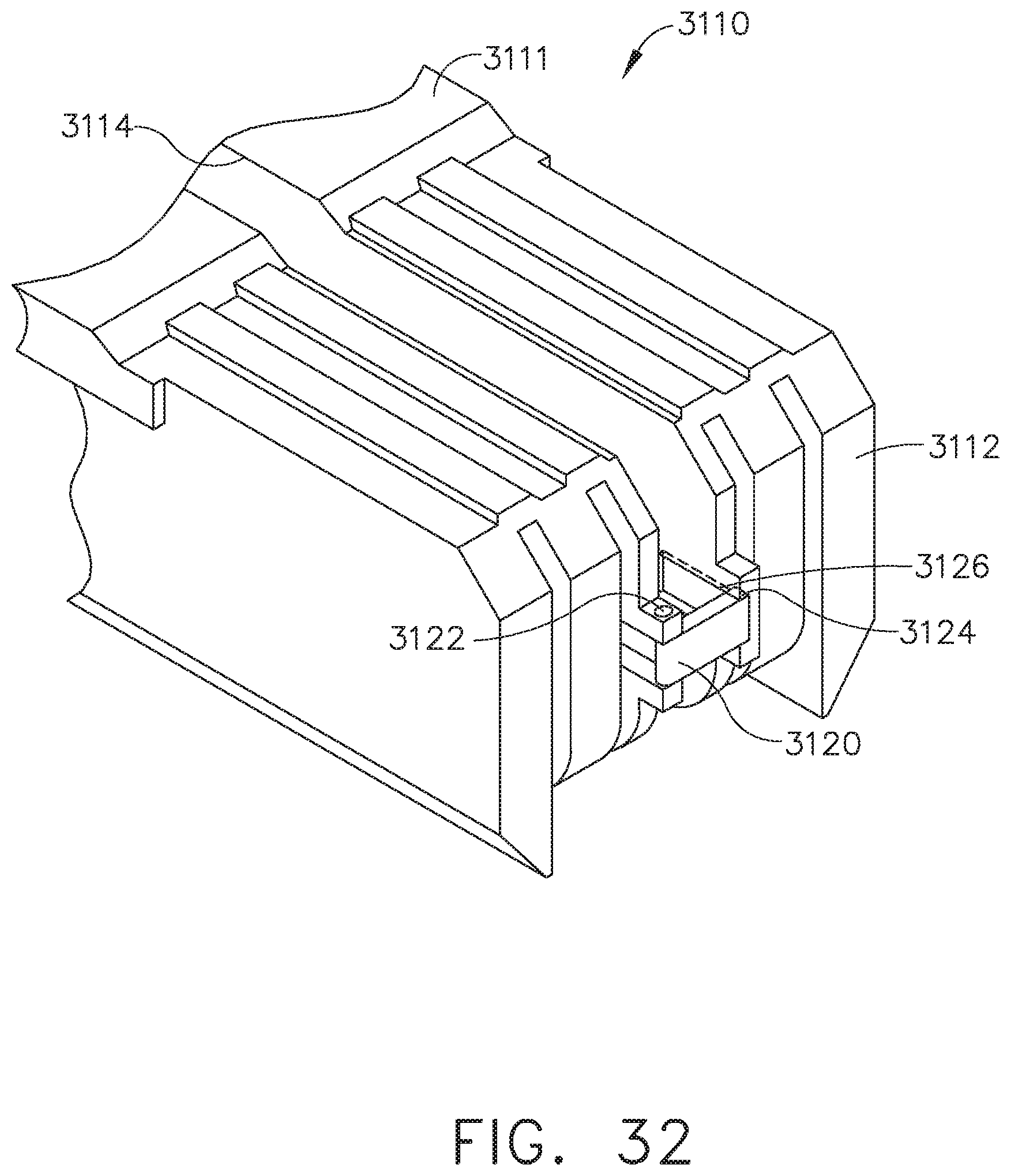
D00026

D00027

D00028

D00029

D00030

D00031

D00032

D00033

D00034

D00035

D00036

D00037

D00038

D00039

D00040

D00041

D00042

D00043

D00044

D00045

D00046

D00047

D00048

D00049

D00050

D00051

D00052

D00053

D00054

D00055

D00056

D00057

D00058

D00059

D00060

D00061

D00062

D00063

D00064

D00065

D00066

D00067

D00068

XML
uspto.report is an independent third-party trademark research tool that is not affiliated, endorsed, or sponsored by the United States Patent and Trademark Office (USPTO) or any other governmental organization. The information provided by uspto.report is based on publicly available data at the time of writing and is intended for informational purposes only.
While we strive to provide accurate and up-to-date information, we do not guarantee the accuracy, completeness, reliability, or suitability of the information displayed on this site. The use of this site is at your own risk. Any reliance you place on such information is therefore strictly at your own risk.
All official trademark data, including owner information, should be verified by visiting the official USPTO website at www.uspto.gov. This site is not intended to replace professional legal advice and should not be used as a substitute for consulting with a legal professional who is knowledgeable about trademark law.