Apparatus For Improving Usability And Accuracy For Physiological Measurement
CHEN; Yenyu ; et al.
U.S. patent application number 16/494315 was filed with the patent office on 2020-12-03 for apparatus for improving usability and accuracy for physiological measurement. This patent application is currently assigned to iXensor CO., LTD.. The applicant listed for this patent is iXensor CO., LTD.. Invention is credited to Yenyu CHEN, Jheng Long JIANG, Chieh Yu LIN, Chun Hun SHEN, Yao Ching TSAI.
| Application Number | 20200375543 16/494315 |
| Document ID | / |
| Family ID | 1000005036610 |
| Filed Date | 2020-12-03 |


View All Diagrams
| United States Patent Application | 20200375543 |
| Kind Code | A1 |
| CHEN; Yenyu ; et al. | December 3, 2020 |
APPARATUS FOR IMPROVING USABILITY AND ACCURACY FOR PHYSIOLOGICAL MEASUREMENT
Abstract
Example apparatus are provided to measure characteristics of a test strip. The apparatus may include an accessory for a mobile device to measure characteristics of a test strip. The accessory may include a mobile device adaptor and a test strip adaptor. The mobile device adaptor may include a first sheath and a second sheath coupled to the first sheath to secure the mobile device. The test strip adaptor may be detachably coupled to the mobile device adapter. The test strip adaptor is configured to receive different types of test strips.
| Inventors: | CHEN; Yenyu; (Taipei, TW) ; TSAI; Yao Ching; (Taipei, TW) ; JIANG; Jheng Long; (Taipei, TW) ; LIN; Chieh Yu; (Taipei, TW) ; SHEN; Chun Hun; (Taipei, TW) | ||||||||||
| Applicant: |
|
||||||||||
|---|---|---|---|---|---|---|---|---|---|---|---|
| Assignee: | iXensor CO., LTD. Taipei TW |
||||||||||
| Family ID: | 1000005036610 | ||||||||||
| Appl. No.: | 16/494315 | ||||||||||
| Filed: | March 16, 2018 | ||||||||||
| PCT Filed: | March 16, 2018 | ||||||||||
| PCT NO: | PCT/CN2018/079304 | ||||||||||
| 371 Date: | September 16, 2019 |
Related U.S. Patent Documents
| Application Number | Filing Date | Patent Number | ||
|---|---|---|---|---|
| 62472585 | Mar 17, 2017 | |||
| Current U.S. Class: | 1/1 |
| Current CPC Class: | A61B 5/150358 20130101; A61B 5/6898 20130101; G01N 21/8483 20130101; A61B 5/0059 20130101; A61B 5/14532 20130101; A61B 2560/0233 20130101 |
| International Class: | A61B 5/00 20060101 A61B005/00; A61B 5/15 20060101 A61B005/15; A61B 5/145 20060101 A61B005/145 |
Claims
1. An accessory for a mobile device to measure characteristics of a test strip, the accessory comprising: a mobile device adapter comprising: a first sheath, wherein the first sheath further defines: a camera hole corresponding to a camera of the mobile device to capture an image of a test strip placed in the test strip adaptor; an illuminating screen opening corresponding to a first portion of a screen of the mobile device and configured to allow light from the first portion of the screen to illuminate the test strip placed in the test strip adaptor; and a display screen opening corresponding to a second portion of the screen of the mobile device; and a second sheath coupled to the first sheath to secure the mobile device; and a test strip adapter detachably coupled to the mobile device adapter, wherein the test strip adaptor is configured to receive different types of test strips.
2. The accessory of claim 1, wherein: the mobile device adapter further comprises a set of guiding elements formed on the first sheath; and the test strip adaptor further defines a set of main bracket guiding grooves, wherein the main bracket guiding grooves are configured to receive the guiding elements.
3. (canceled)
4. The accessory of claim 1, wherein the mobile device adapter further comprises: a latch disposed between the first sheath and the second sheath; and a knob coupled to the latch and disposed in a first sheath opening defined in the second sheath.
5. The accessory of claim 4, wherein the second sheath further defines a latch guiding groove to receive the latch.
6. The accessory of claim 4, wherein the test strip adapter further defines a set of latch housing to receive a latch protruding element of the latch so that the knob is configured to actuate a movement of the latch protruding element to lock the test strip adapter to the mobile device adaptor or to unlock the test strip adaptor from the mobile device adaptor.
7. An accessory for a mobile device to measure characteristics of a test strip, the accessory comprising: a mobile device adapter defining a camera hole and an illuminating screen opening; and a test strip adapter configured to lock to the mobile device adapter, the test strip adaptor comprising: a case defining a first inserting entry and a second inserting entry to receive a test strip; a main bracket configured to engage with the case and defining a main detecting opening that corresponds to and is aligned with the camera hole and the illuminating screen opening; a test strip bracket disposed in the main bracket and configured to receive the test strip inserted via the first inserting entry or the second inserting entry; and a light guide configured to couple to a side of the main bracket.
8. The accessory of claim 7, wherein the main bracket further comprises: a first connecting element engaged with the case; and a second connecting element and a pivot both secured with the light guide.
9. The accessory of claim 8, wherein the case further defines a connecting opening to engage with the first connecting element.
10. The accessory of claim 8, wherein the light guide further comprises a notch engaged with the pivot and defines a light guide connecting opening engaged with the second connecting element.
11. An accessory for a mobile device to measure characteristics of a test strip, the accessory comprising: a mobile device adapter defining a camera hole and an illuminating screen opening; and a test strip adapter configured to couple to the mobile device adapter, the test strip adaptor comprising: a case that defines a first inserting entry and a second inserting entry to receive a test strip; a main bracket configured to engage with the case, wherein the main bracket defines a main detecting opening that corresponds to and aligns with the camera hole and the illuminating screen opening; a test strip bracket configured to receive the test strip inserted from either the first inserting entry or the second inserting entry, wherein the test strip bracket defines at least one detecting opening; and a light guide coupled to the main bracket.
12. The accessory of claim 11, wherein the main bracket further comprises a first door engaged with a first torsion spring engaged with the main bracket, and the first door is operatively to move in response to the test strip being inserted from the first inserting entry.
13. The accessory of claim 11, wherein the main bracket further comprises a second door, which when the second door is in a first position on the main bracket, the second door covers the main detecting opening, and in response to the test strip being inserted from the second inserting entry, the second door is operatively to move to a second position on the main bracket to leave the main detecting opening at least partially unobstructed.
14. The accessory of claim 11, wherein the case further comprises a sliding module configured to slide from one side of the case to another side of the case to cover or reveal the second inserting entry.
15. The accessory of claim 14, wherein the main bracket further comprises a lock engaged with a tension spring on the main bracket to lock the sliding module.
16. The accessory of claim 11, wherein the test strip bracket further comprises a handle operatively configured to maintain the test strip bracket in a first state or a second state with respect to the main bracket, wherein: in the first state, the at least one detecting opening is configured to align with the main detecting opening; and in the second state, the main detecting opening is at least partially unobstructed from a second door of the main bracket.
17. The accessory of claim 16, in the second state, in response to a first test strip being inserted from the first inserting entry, a first reaction area of the first test strip is aligned with the main detecting opening.
18. The accessory of claim 16, in the second state, in response to a calibration test strip being inserted from the first inserting entry, a plurality of colored calibration blocks of the calibration test strip are aligned with the main detecting opening.
19. The accessory of claim 16, in the first state, in response to a second test strip being inserted from the second inserting entry, a second reaction area of the second test strip is aligned with the second detecting opening and the main detecting opening.
20. The accessory of claim 16, in the first state, in response to a third test strip being inserted from the second inserting entry, a third reaction area of the third test strip is aligned with the third detecting opening and the main detecting opening.
Description
CROSS-REFERENCE TO RELATED APPLICATION
[0001] This application claims the benefit of U.S. Provisional Application No. 62/472,585 filed Mar. 17, 2017, which is incorporated by reference in its entirety.
BACKGROUND
[0002] In recent years, in-vitro diagnosis (IVD) devices, especially blood glucose meters, have gained wide adoption among patients with chronic diseases. In order to take measurements, patients usually have to carry standalone IVD devices with them at all times.
[0003] For typical IVD measurements, test strips consisting enzyme and reagent are used. Upon receiving the sample fluid, the test strip's characteristics, such as electrical impedance or color, change according to the concentration of the targeted analyte, such as blood glucose or blood cholesterol.
[0004] Optochemistry-based IVD systems usually comprises test strips that change color according to the concentration of analyte received, specific light sources that illuminate on strips, optical sensors that detect scattering light, and light-isolating cases.
[0005] These existing IVD devices tend to work with a particular type of test strip. For patients needing to conduct multiple tests involving different types of test strips, they would be required to obtain and carry multiple IVD devices with them.
SUMMARY
[0006] In examples of the present disclosure, apparatus are provided to measure characteristics of a test strip. The apparatus may include an accessory for a mobile device to measure characteristics of a test strip. The accessory may include a mobile device adaptor and a test strip adaptor. The mobile device adaptor may include a first sheath and a second sheath coupled to the first sheath to secure the mobile device. The test strip adaptor may be detachably coupled to the mobile device adapter. The test strip adaptor is configured to receive different types of test strips.
BRIEF DESCRIPTION OF THE DRAWINGS
[0007] The foregoing and other features of the present disclosure will become more fully apparent from the following description and appended claims, taken in conjunction with the accompanying drawings. These drawings depict only several embodiments in accordance with the disclosure and are therefore not to be considered limiting of its scope. The disclosure will be described with additional specificity and detail through use of the accompanying drawings.
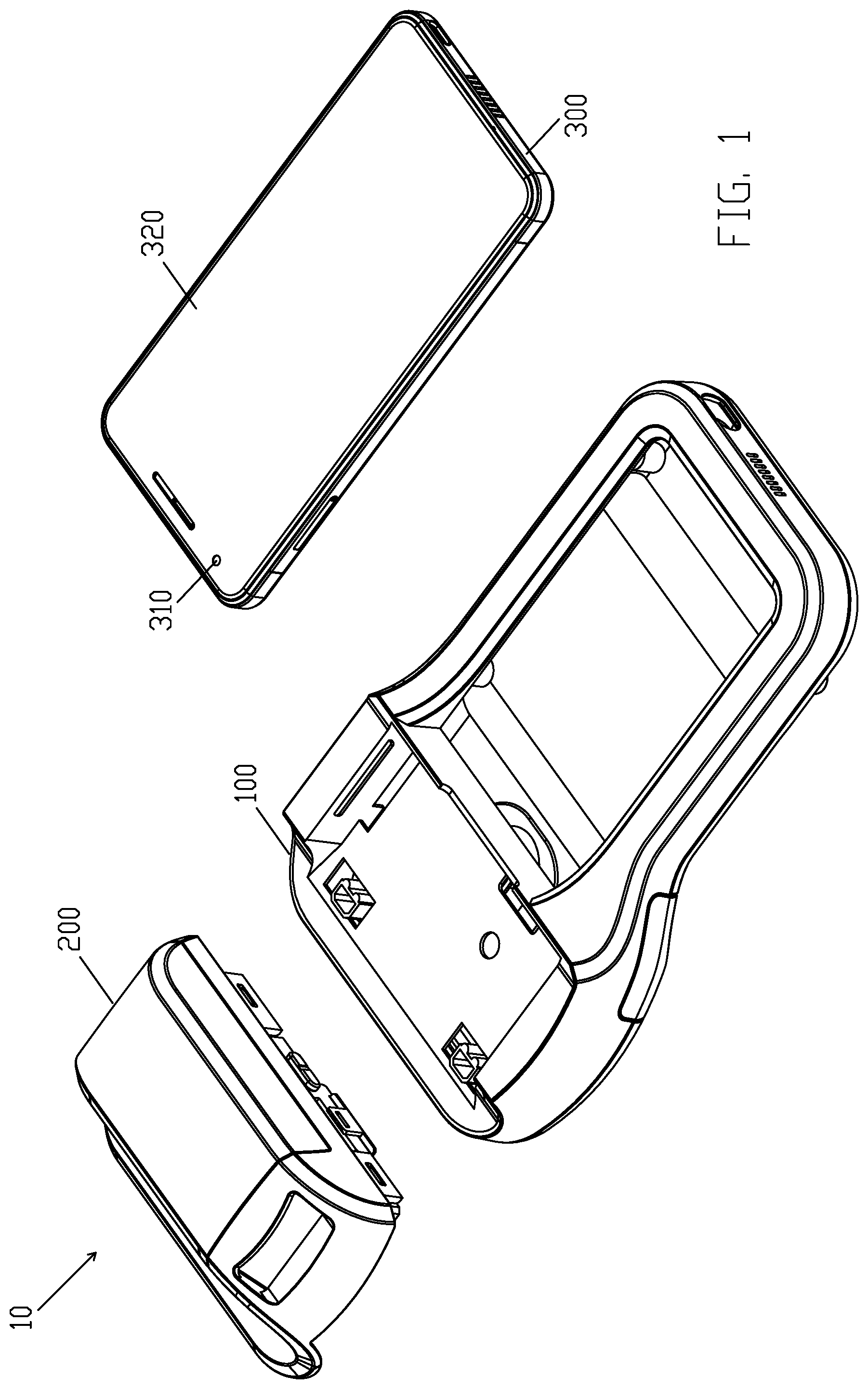
[0008] FIG. 1 illustrates a perspective view of mobile device accessory 10, according to some embodiments of the present disclosure.
[0009] FIG. 2A illustrates an exploded top perspective view of mobile device adaptor 100, according to some embodiments of the present disclosure.
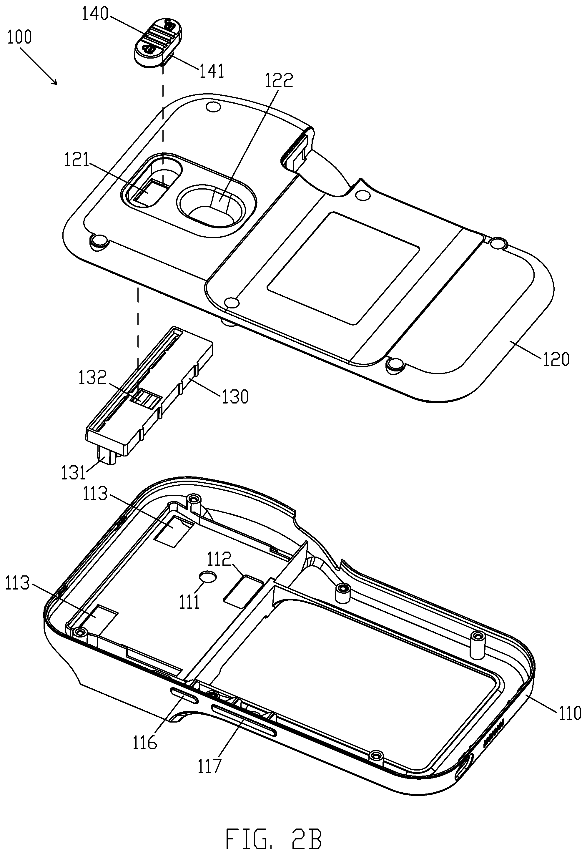
[0010] FIG. 2B illustrates an exploded bottom perspective view of mobile device adaptor 100, according to some embodiments of the present disclosure.
[0011] FIG. 3A illustrates an exploded front perspective view of test strip adaptor 200, according to some embodiments of the present disclosure.
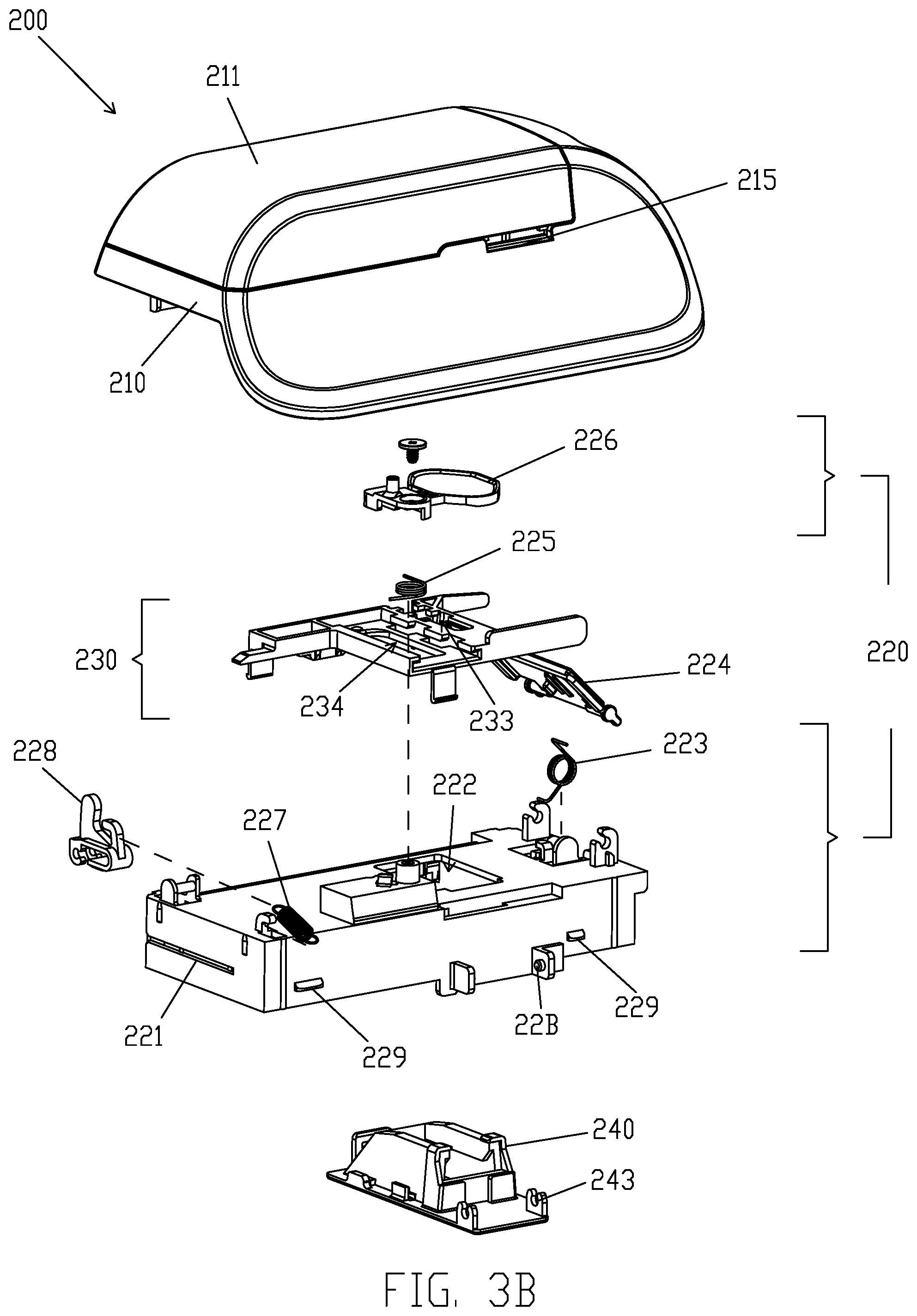
[0012] FIG. 3B illustrates an exploded back perspective view of test strip adaptor 200, according to some embodiments of the present disclosure.
[0013] FIG. 3C illustrates an exploded bottom-front perspective view of test strip adaptor 200, according to some embodiments of the present disclosure.
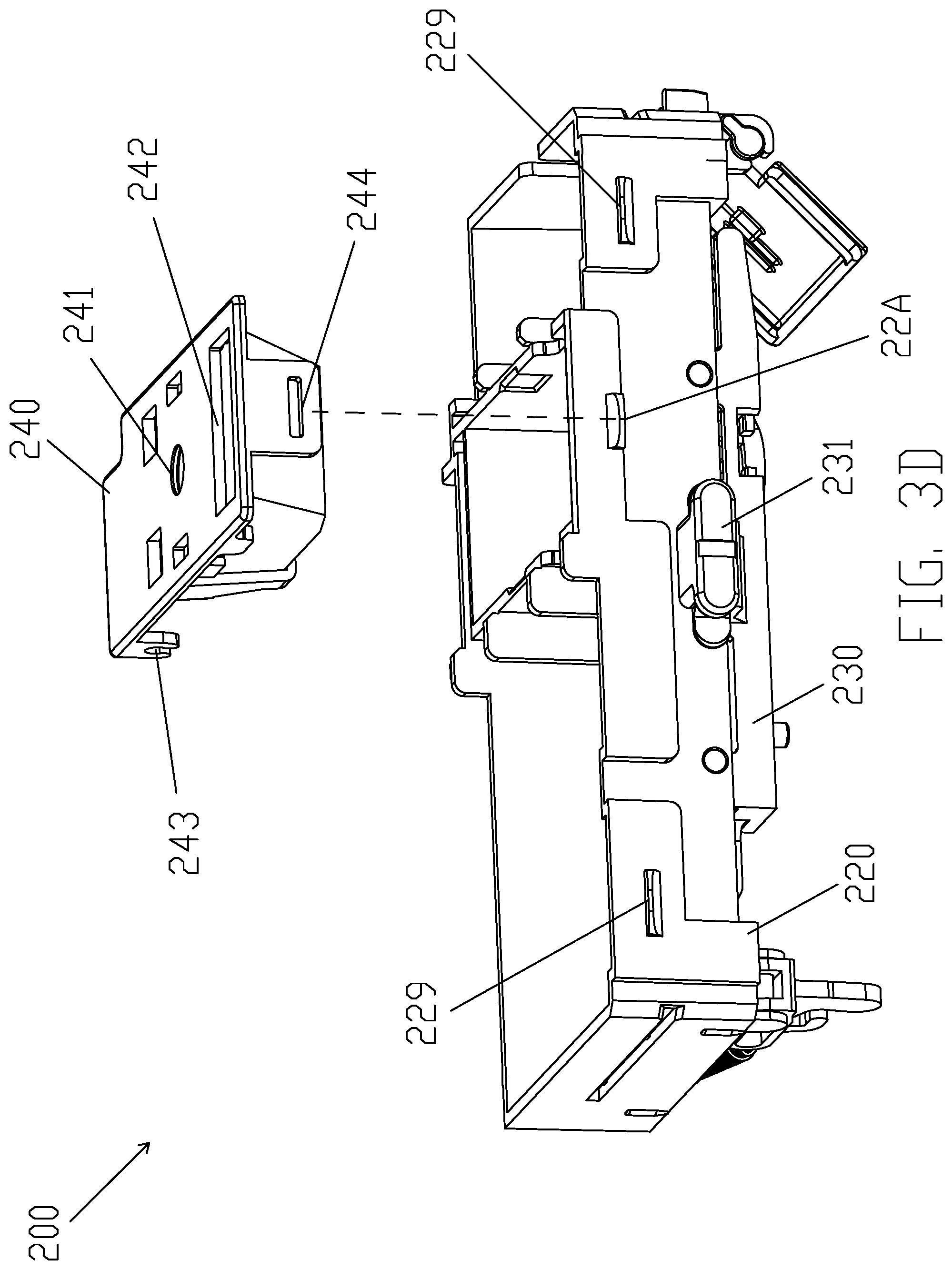
[0014] FIG. 3D illustrates an exploded bottom-back perspective view of test strip adaptor 200, according to some embodiments of the present disclosure.
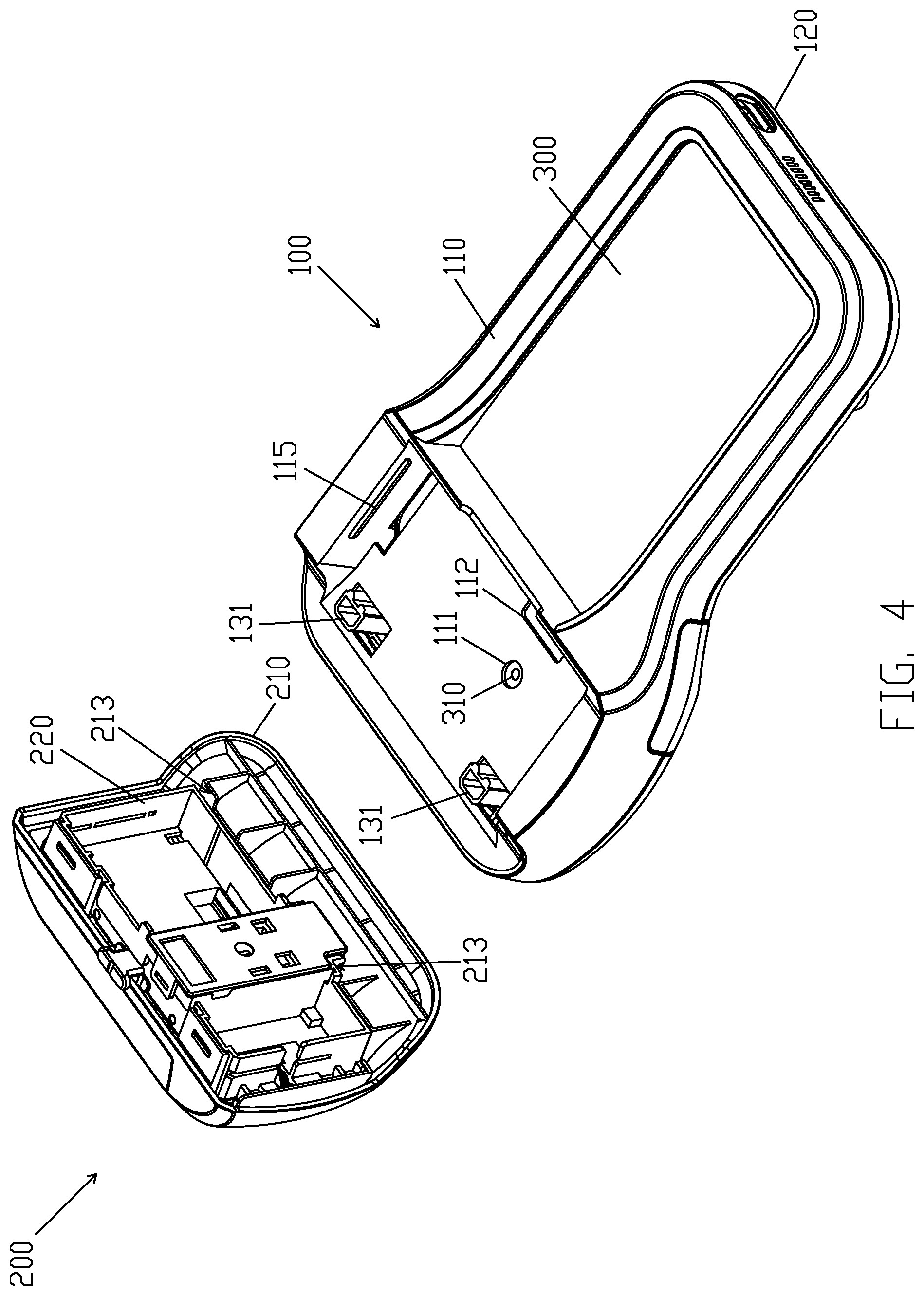
[0015] FIG. 4 illustrates a perspective view of mobile device adaptor 100 and test strip adaptor 200, according to some embodiments of the present disclosure.
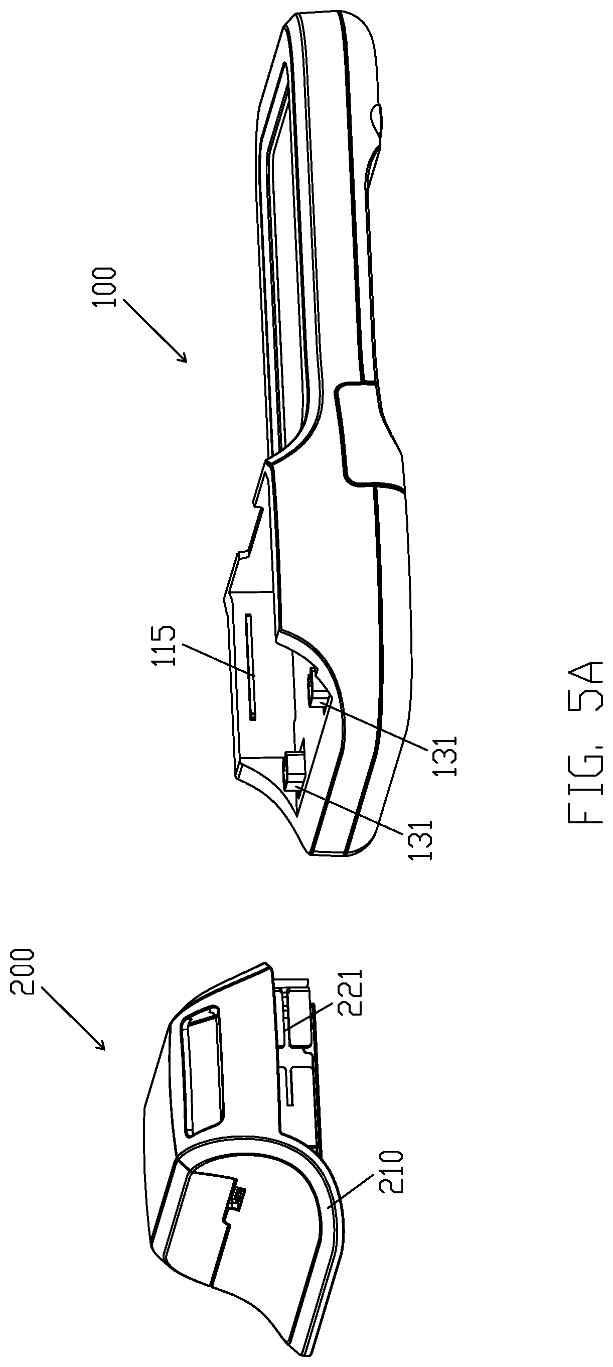
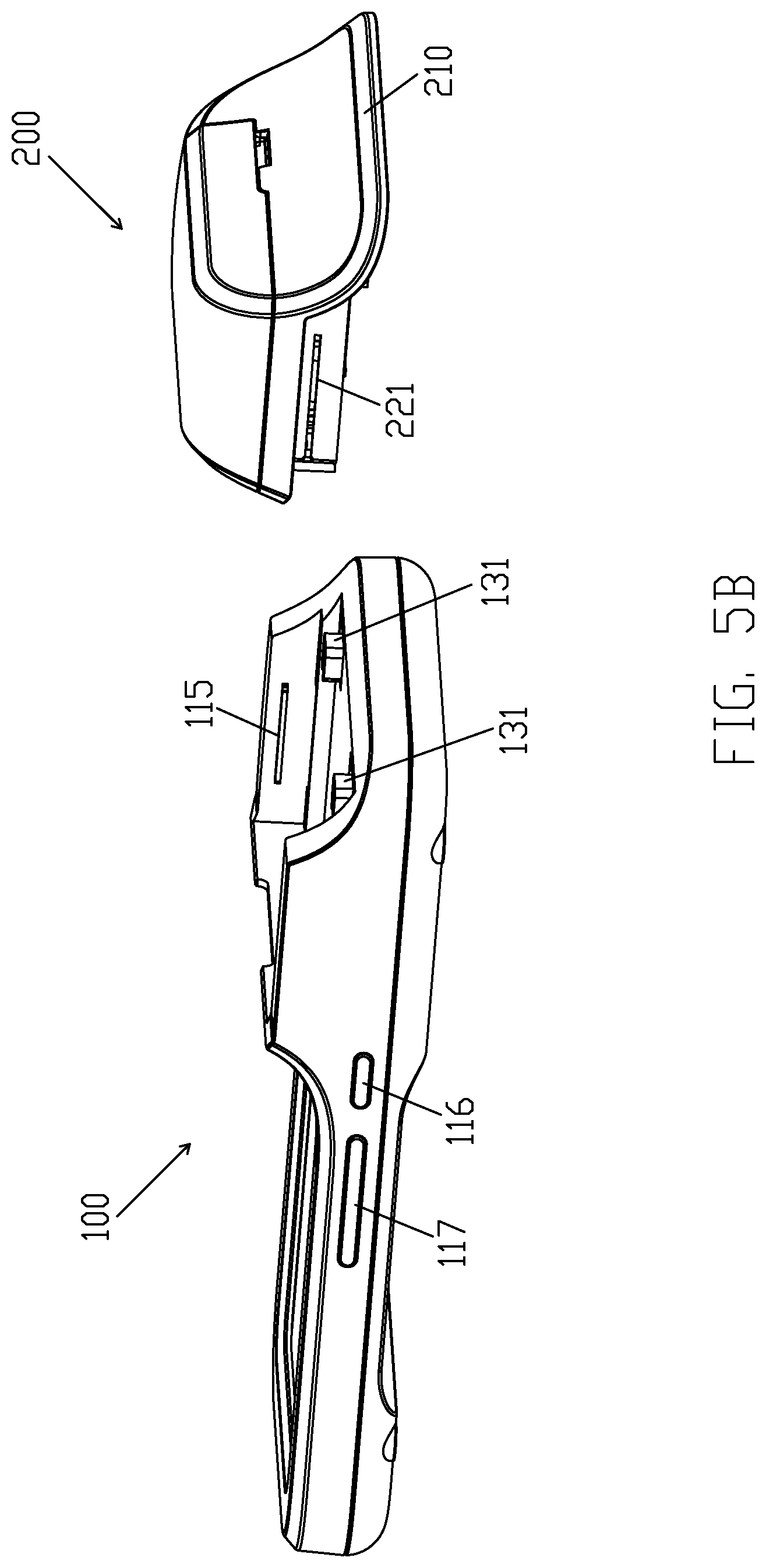
[0016] FIGS. 5A and 5B illustrate another two perspective views of mobile device adaptor 100 and test strip adaptor 200, according to some embodiments of the present disclosure.
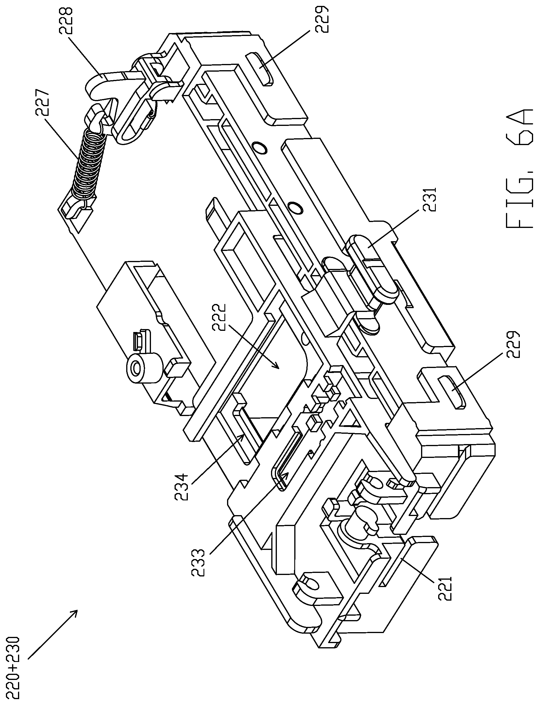
[0017] FIGS. 6A, 6B and 6C illustrate perspective views of main bracket 220 and test strip bracket 230, according to some embodiments of the present disclosure.
[0018] FIGS. 7A, 7B, 7C and 7D illustrate different type of test strips, according to some embodiments of the present disclosure.
[0019] FIG. 8A illustrates a front perspective view of main bracket 220 and test strip bracket 230 prior to middle sized test strip 410 being inserted into second detecting opening 234 and second inserting entry 215, according to some embodiments of the present disclosure.
[0020] FIG. 8B illustrates back perspective view of main bracket 220 and test strip bracket 230 prior to middle sized test strip 410 being inserted into second detecting opening 234 and second inserting entry 215, according to some embodiments of the present disclosure.
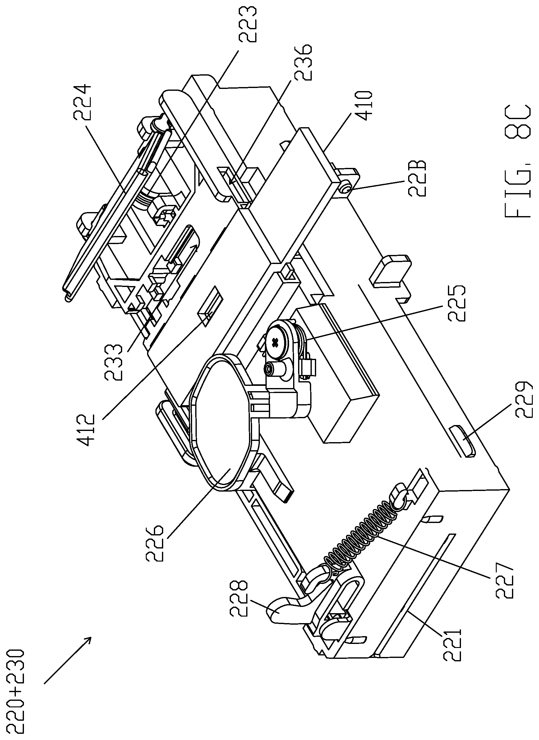
[0021] FIG. 8C illustrates front perspective view of main bracket 220 and test strip bracket 230 after middle sized test strip 410 being inserted into second detecting opening 234 and second inserting entry 215, according to some embodiments of the present disclosure.
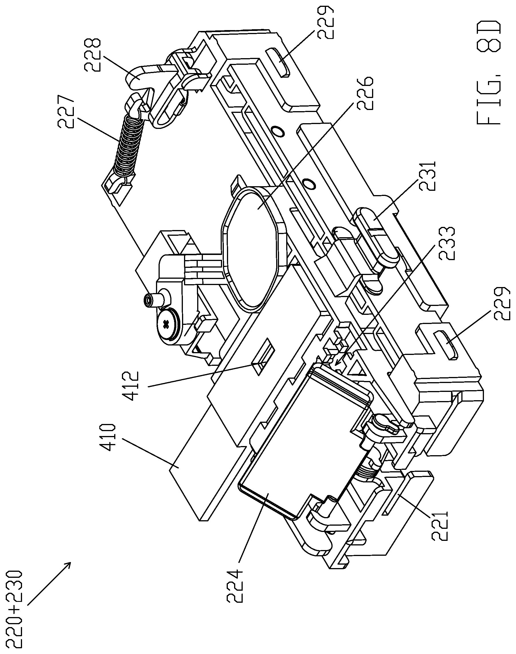
[0022] FIG. 8D illustrates back perspective view of main bracket 220 and test strip bracket 230 after middle sized test strip 410 being inserted into second detecting opening 234 and second inserting entry 215, according to some embodiments of the present disclosure.
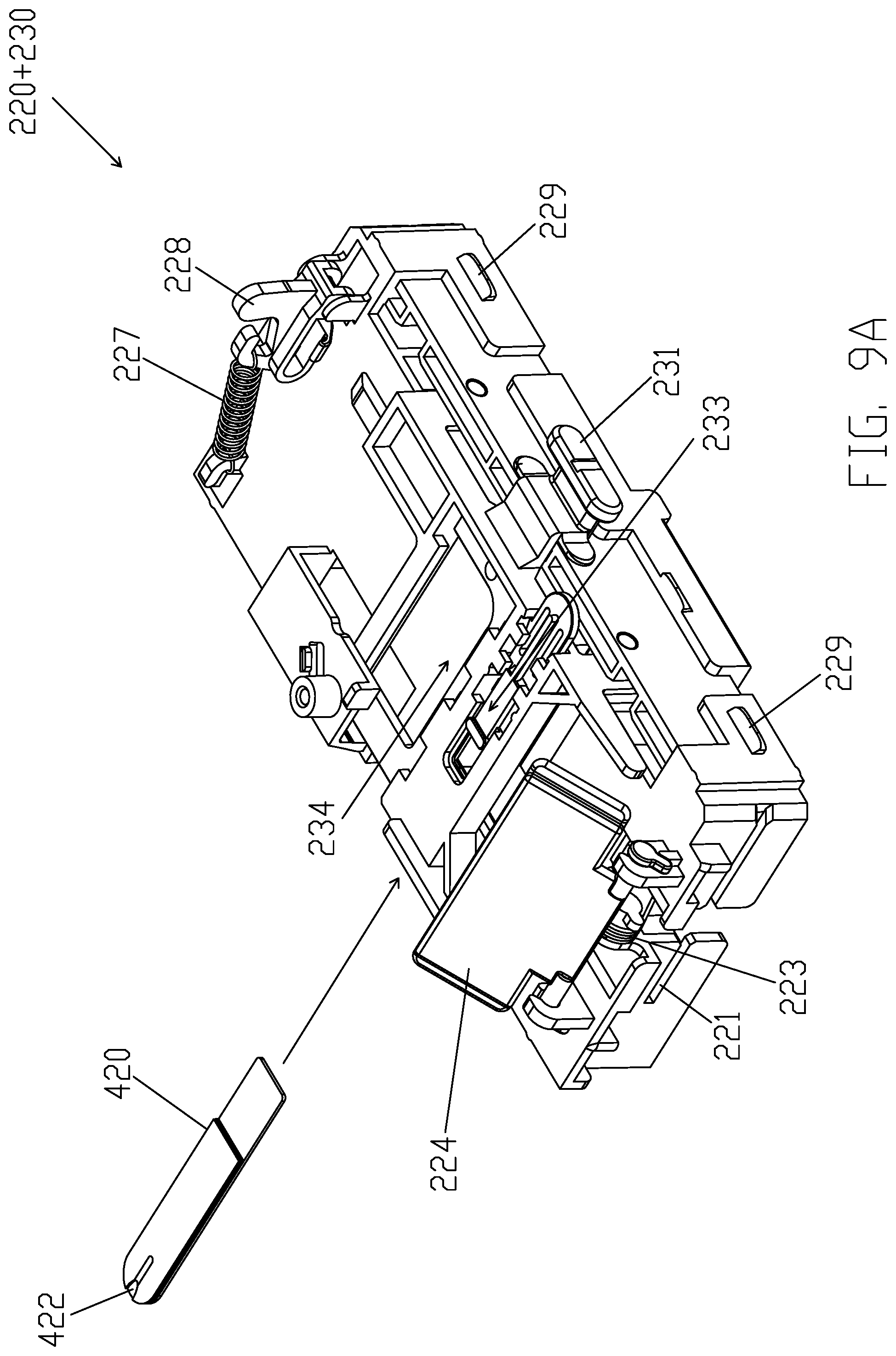
[0023] FIG. 9A illustrates front perspective view of main bracket 220 and test strip bracket 230 prior to small sized test strip 420 being inserted into first detecting opening 233 and second inserting entry 215, according to some embodiments of the present disclosure.
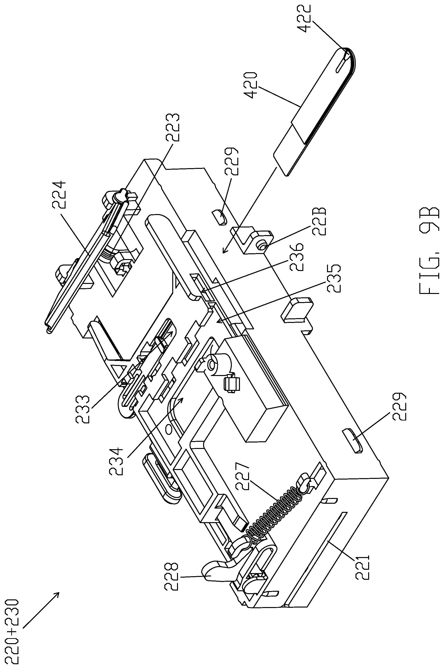
[0024] FIG. 9B illustrates back perspective view of main bracket 220 and test strip bracket 230 prior to small sized test strip 420 being inserted into first detecting opening 233 and second inserting entry 215, according to some embodiments of the present disclosure.
[0025] FIG. 9C illustrates front perspective view of main bracket 220 and test strip bracket 230 after small sized test strip 420 being inserted into first detecting opening 233 and second inserting entry 215, according to some embodiments of the present disclosure.
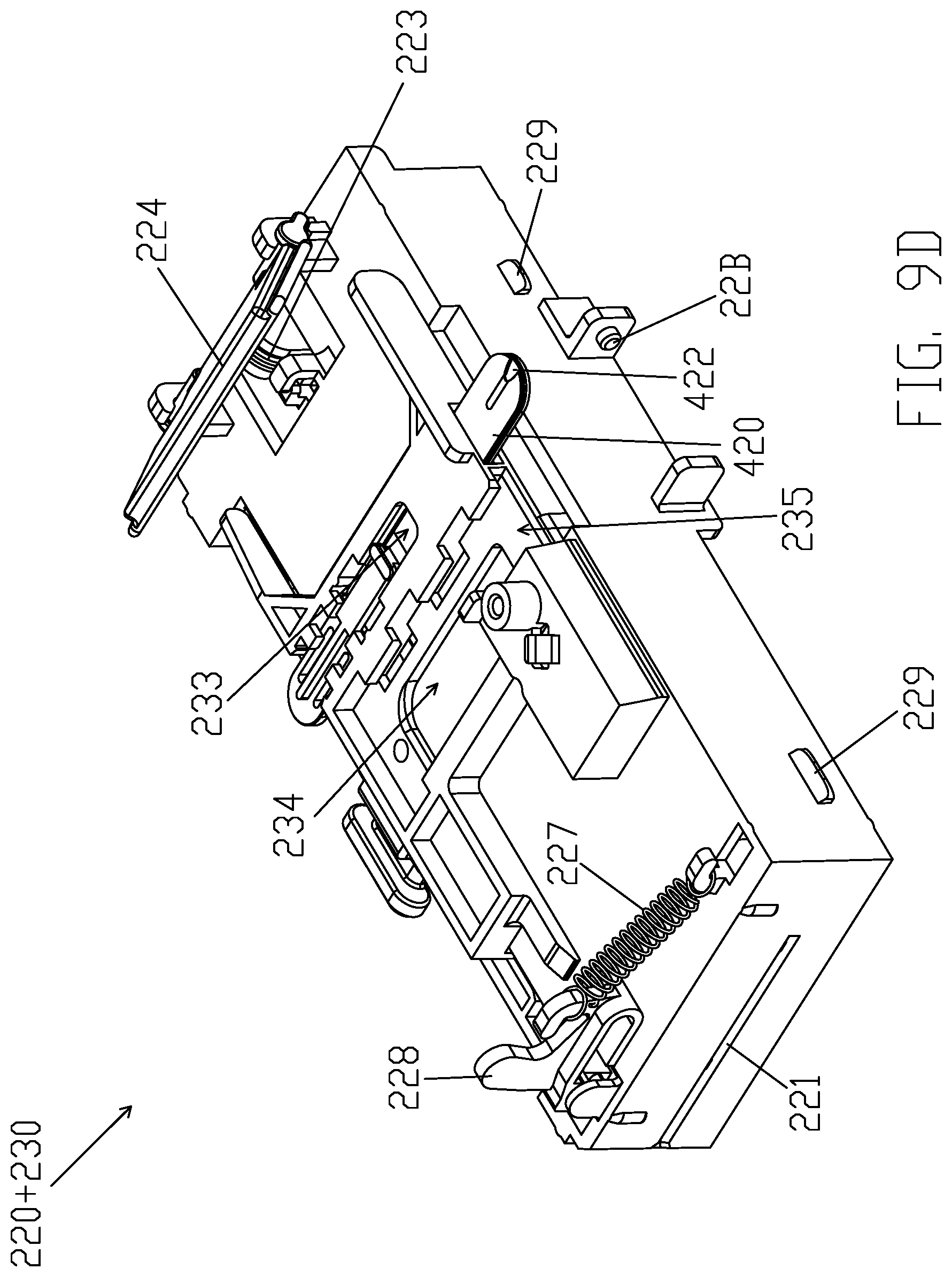
[0026] FIG. 9D illustrates back perspective view of main bracket 220 and test strip bracket 230 after small sized test strip 420 being inserted into first detecting opening 233 and second inserting entry 215, according to some embodiments of the present disclosure.
[0027] FIG. 10A illustrates front perspective view of main bracket 220 and test strip bracket 230 prior to calibration test strip 430 being inserted into first inserting entry 214, according to some embodiments of the present disclosure.
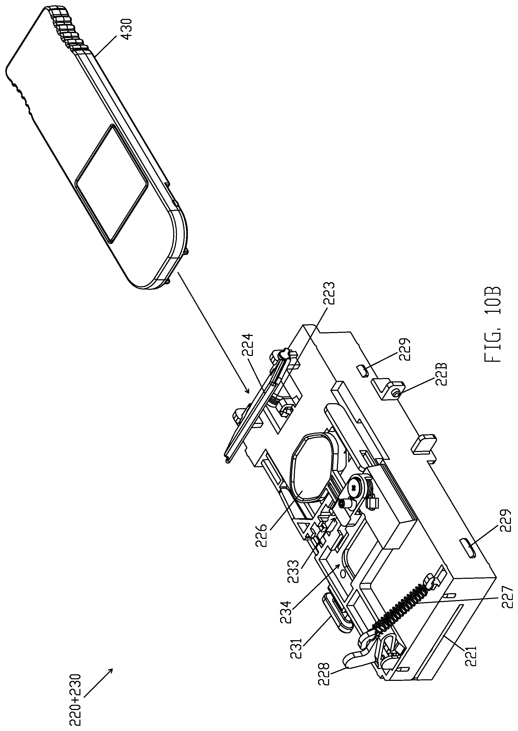
[0028] FIG. 10B illustrates back perspective view of main bracket 220 and test strip bracket 230 prior to calibration test strip 430 being inserted into first inserting entry 214, according to some embodiments of the present disclosure.
[0029] FIG. 10C illustrates front perspective view of main bracket 220 and test strip bracket 230 after calibration test strip 430 being inserted into first inserting entry 214, according to some embodiments of the present disclosure.
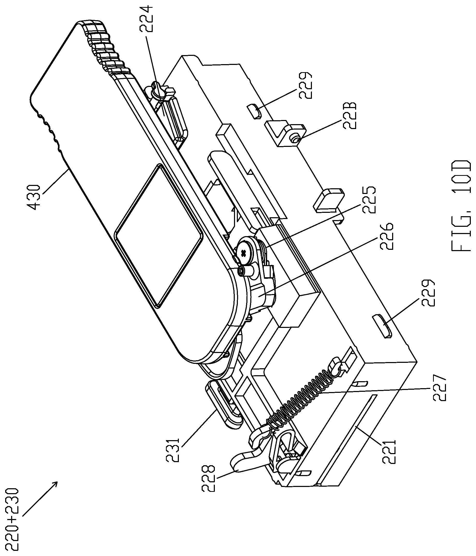
[0030] FIG. 10D illustrates back perspective view of main bracket 220 and test strip bracket 230 after calibration test strip 430 being inserted into first inserting entry 214, according to some embodiments of the present disclosure.
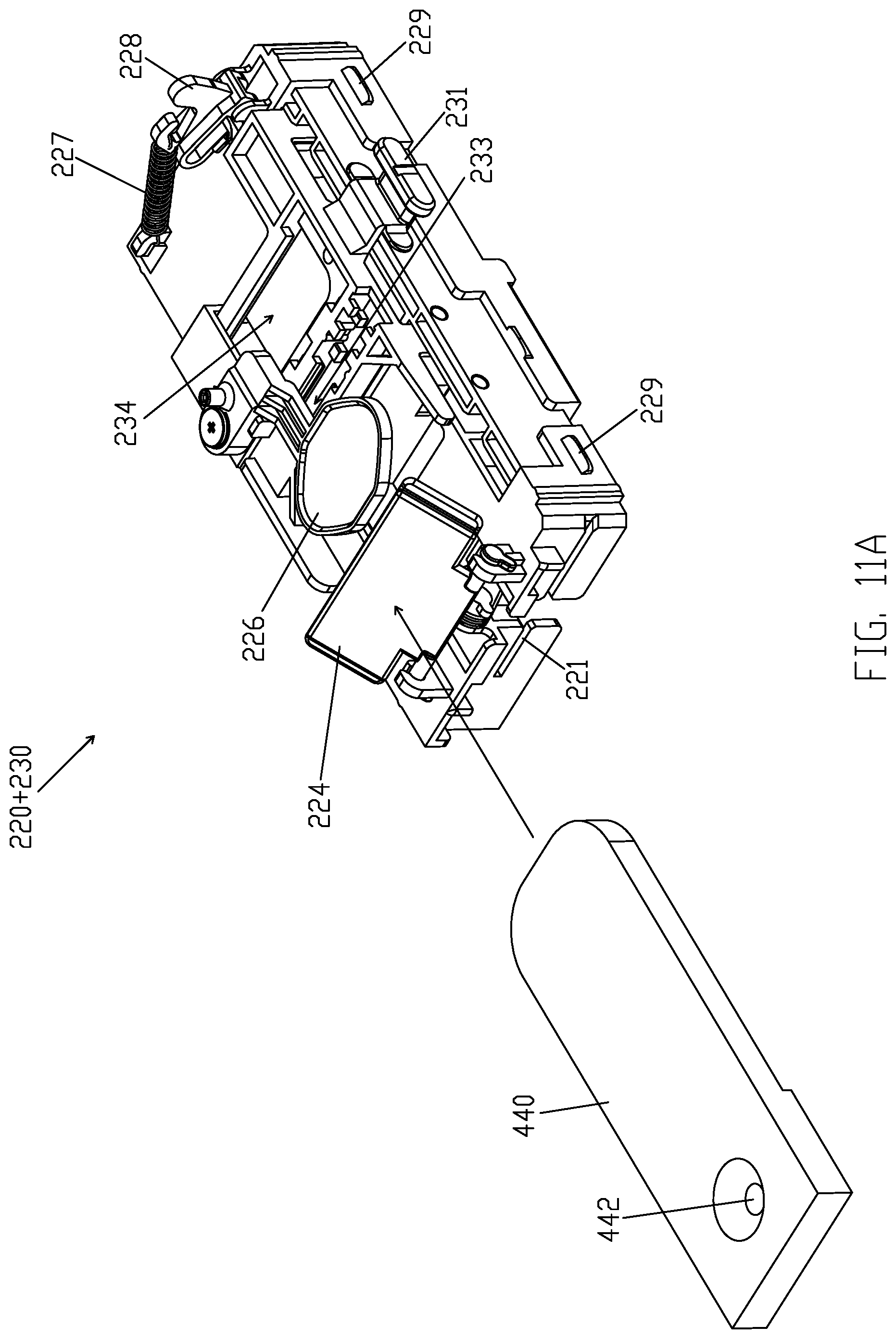
[0031] FIG. 11A illustrates front perspective view of main bracket 220 and test strip bracket 230 prior to large sized test strip 440 being inserted into first inserting entry 214, according to some embodiments of the present disclosure.
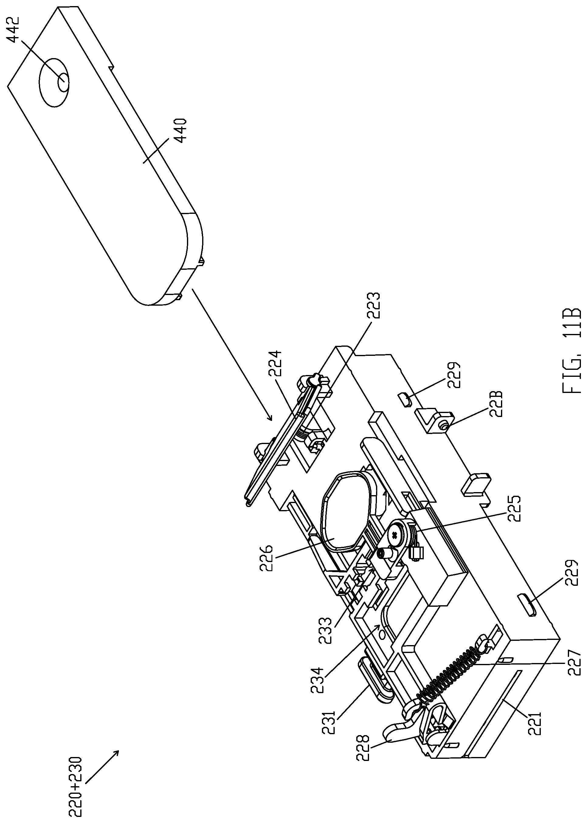
[0032] FIG. 11B illustrates back perspective views of main bracket 220 and test strip bracket 230 prior to large sized test strip 440 being inserted into first inserting entry 214, according to some embodiments of the present disclosure.
[0033] FIG. 11C illustrates front perspective view of main bracket 220 and test strip bracket 230 after large sized test strip 440 being inserted into first inserting entry 214, according to some embodiments of the present disclosure.
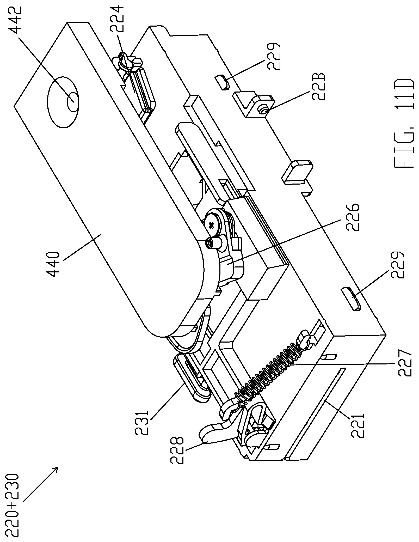
[0034] FIG. 11D illustrates back perspective view of main bracket 220 and test strip bracket 230 after large sized test strip 440 being inserted into first inserting entry 214, according to some embodiments of the present disclosure.
DETAILED DESCRIPTION
[0035] In the following detailed description, reference is made to the accompanying drawings, which form a part hereof. In the drawings, similar symbols typically identify similar components and same numerals typically identify same components, unless context dictates otherwise. The illustrative embodiments described in the detailed description and drawings are not meant to be limiting. Other embodiments may be utilized, and other changes may be made, without departing from the spirit or scope of the subject matter presented here. It will be readily understood that the aspects of the present disclosure, as generally described herein, and illustrated in the drawings, can be arranged, substituted, combined, and designed in a wide variety of different configurations, all of which are explicitly contemplated herein.
[0036] FIG. 1 illustrates a perspective view of mobile device accessory 10, according to some embodiments of the present disclosure. In some embodiments, mobile device accessory 10 includes mobile device adaptor 100, test strip adaptor 200 and mobile device 300. Mobile device adaptor 100 may be configured to lock with test strip adaptor 200. Mobile device adaptor 100 may be also configured to receive mobile device 300. In some embodiments, mobile device 300 includes camera 310 and screen 320.
[0037] FIG. 2A illustrates an exploded top perspective view of mobile device adaptor 100, according to some embodiments of the present disclosure. FIG. 2B illustrates an exploded bottom perspective view of mobile device adaptor 100, according to some embodiments of the present disclosure. In conjunction with FIG. 2A and FIG. 2B, mobile device adaptor 100 may include first sheath (e.g., top sheath 110), second sheath (e.g., bottom sheath 120), a locking mechanism (e.g., latch 130 and knob 140). Top sheath 110 may be configured to couple to bottom sheath 120. Top sheath 110 and bottom sheath 120, once coupled to one another, secure mobile device 300.
[0038] Referring to FIG. 2A, in some embodiments, top sheath 110 defines camera hole 111, illuminating screen opening 112, a set of latch openings 113, a display opening 114 and a set of guiding elements 115. In some embodiments, bottom sheath 120 includes latch guiding groove 123.
[0039] In some embodiments, in conjunction with FIG. 1, in response to mobile device 300 being received between top sheath 110 and bottom sheath 120, camera hole 111 and illuminating screen opening 112 are configured to respectively correspond to camera 310 and a first portion of screen 320 of mobile device 300. First portion of screen 320 is configured to illuminate a reaction area of a test strip and camera 310 is configured to capture an image of the reaction area. In addition, display opening 114 may correspond to a second portion of screen 320 to provide a display for a user.
[0040] Referring to FIG. 2B, in some embodiments, top sheath 110 includes power button 116 and volume button 117 configured for a user to control mobile device 300 received between top sheath 110 and bottom sheath 120. In some embodiments, bottom sheath 120 defines first sheath opening 121 and second sheath opening 122. First sheath opening 121 may be configured to receive knob 140. Second sheath opening 122 may be configured to correspond to another camera (not shown) of mobile device 300.
[0041] In FIG. 2B, in some embodiments, latch 130 is configured to dispose between top sheath 110 and bottom sheath 120. Latch 130 may include a set of latch protruding elements 131. Latch protruding elements 131 may be configured to insert through latch openings 113. In some embodiments, knob 140 may include knob clip 141, which can be coupled to a corresponding knob opening 132 on latch 130. In conjunction with FIG. 2A, latch 130 may be received in latch guiding groove 123 and configured to slide along latch guiding groove 123 by sliding knob 140 in first sheath opening 121.
[0042] FIG. 3A illustrates an exploded front perspective view of test strip adaptor 200, according to some embodiments of the present disclosure. FIG. 3B illustrates an exploded back perspective view of test strip adaptor 200, according to some embodiments of the present disclosure. In some embodiments, test strip adaptor 200 includes case 210, main bracket 220, test strip bracket 230 and light guide 240. In some embodiments, case 210 is configured to engage with main bracket 220. In some other embodiments, in response to case 210 being engaged with main bracket 220, test strip bracket 230 is configured to dispose in a space defined by engaged case 210 and main bracket 220. In addition, light guide 240 is configured to couple to one side of main bracket 220, while test strip bracket 230 is coupled to another side of main bracket 220.
[0043] In conjunction with FIGS. 3A and 3B, in some embodiments, case 210 is coupled to sliding module 211 via a sliding mechanism. In addition, case 210 defines a set of connecting openings 212, first inserting entry 214 and second inserting entry 215. Sliding module 211 may be configured to cover or reveal second inserting entry 215 as sliding module 211 slides from one side of case 210 to another side of case 210.
[0044] In conjunction with FIGS. 3A and 3B, in some embodiments, main bracket 220 defines a set of main bracket guiding grooves 221 and main detecting opening 222. In addition, in some embodiments, main bracket 220 includes first torsion spring 223, first door 224, second torsion spring 225, second door 226, tension spring 227, lock 228, a set of first connecting elements 229, and pivot 22B.
[0045] In conjunction with FIGS. 3A and 3B, in some embodiments, test strip bracket 230 may include handle 231. In addition, in some embodiments, test strip bracket 230 defines first detecting opening 233 and second detecting opening 234. In conjunction with FIGS. 3A and 3B, in some embodiments, light guide 240 includes a set of notches 243 and defines light guide connecting opening 244.
[0046] In some embodiments, case 210 is configured to engage with main bracket 220. Referring back to FIG. 3A, connecting openings 212 are extended at one side of case 210. In some embodiments, connecting openings 212 correspond to and are configured to engage with first connecting elements 229 of main bracket 220. In response to engagement of first connecting elements 229 and connecting openings 212, case 210 is engaged with main bracket 220.
[0047] In some embodiments, some elements of main bracket 220 are described here in detail. Main detecting opening 222 may be a through opening defined on main bracket 220. In addition, in conjunction with FIG. 2A, main detecting opening 222 is configured to correspond to and align with camera hole 111 and illuminating screen opening 112 of top sheath 110.
[0048] In some embodiments, referring to FIG. 3A, at one side of main bracket 220, one end of first torsion spring 223 is configured to engage with main bracket 220. The other end of first torsion spring 223 is configured to engage with first door 224. In some embodiments, first door 224 is configured to cover first inserting entry 214 when there is no test strip inserted into first inserting entry 214. In some embodiments, when a test strip is inserted into first inserting entry 214, the test strip pushes first door 224 away so that the test strip can reach main detecting opening 222.
[0049] In some embodiments, referring to FIG. 3A, second torsion spring 225 is disposed on main bracket 220. One end of second torsion spring 225 may be engaged with second door 226 so that second door 226 is configured to be in a first position to cover main detecting opening 222 when second torsion spring 225 maintains a first torsion force or in a second position to reveal main detecting opening 222 when second torsion spring 225 maintains a second torsion force. In some embodiments, when second door 226 is in the first position, second door 226 may cover main detecting opening 222 and protect camera 310 from being polluted by potential pollutants (e.g., dust or blood on test strip). In some embodiments, when second door 226 is in the second position, second door 226 may leave main detecting opening 222 at least partially unobstructed so that camera 310 may have a light path through main detecting opening 222 to capture one or more images of the reaction area of the test strip. In some embodiments, in response to a test strip being inserted into second inserting entry 215, the test strip may push second door 226 from the first position to the second position to reveal main detecting opening 222.
[0050] In some embodiments, referring to FIGS. 3A and 3B, at the other side of main bracket 220 opposite from the side at which first torsion spring 223 is engaged, tension spring 227 is configured to engage with lock 228 of main bracket 220. The engagement of tension spring 227 and lock 228 is configured to lock or unlock of sliding module 211 with case 210.
[0051] In some embodiments, referring to FIG. 3A, test strip bracket 230 includes handle 231. Handle 231 is at one side of test strip bracket 230. In addition, handle 231 is manually shifted on main bracket 220. Test strip bracket 230 may define first detecting opening 233 and second detecting opening 234. The detecting openings 233 and 234 will be further described in detail below.
[0052] As set forth above, test strip bracket 230 may be configured to dispose in a space defined by engaged case 210 and main bracket 220. FIG. 3C illustrates an exploded bottom-front perspective views of test strip adaptor 200 (case 210 not included for clarity) when the test strip bracket 230 is disposed in main bracket 220, according to some embodiments of the present disclosure. FIG. 3D illustrates an exploded bottom-back perspective views of test strip adaptor 200 (case 210 not included for clarity) when the test strip bracket 230 is disposed in main bracket 220, according to some embodiments of the present disclosure. In FIG. 3D, light guide 240 includes notches 243 and defines light guide connecting opening 244. In conjunction with FIG. 3B, notches 243 may be engaged with pivots 22B to secure light guide 240 to main bracket 220. Similarly, referring back to FIG. 3D, light guide connecting opening 244 is also configured to engage with first connecting element 22A of main bracket 220 to secure light guide 240 to main bracket 220.
[0053] In some embodiments, in FIG. 3C, light guide 240 further defines light guide camera opening 241 and light guide illuminating screen opening 242. In some embodiments, in conjunction with FIG. 3A, light guide camera opening 241 and light guide illuminating screen opening 242 are both unobstructed from main detecting opening 222 of main bracket 220. In addition, in conjunction with FIG. 2A, light guide camera opening 241 may correspond to camera hole 111 of top sheath 110. Similarly, light guide illuminating screen opening 242 may correspond to illuminating screen opening 112 of top sheath 110.
[0054] FIG. 4 illustrates a perspective view of mobile device adaptor 100 and test strip adaptor 200, according to some embodiments of the present disclosure. As set forth above, test strip adaptor 200 may be locked with mobile device adaptor 100. In conjunction with FIGS. 2A and 2B, case 210 may further include latch housings 213 to receive latch protruding elements 131. In some embodiments, knob 140 is configured to actuate the movement of latch protruding elements 131 in latch housings 213 to lock test strip adaptor 200 to mobile device adaptor 100 to or to unlock test strip adaptor 200 from mobile device adaptor 100.
[0055] FIGS. 5A and 5B illustrate another two perspective views of mobile device adaptor 100 and test strip adaptor 200, according to some embodiments of the present disclosure. In conjunction with FIGS. 3A and 3B, main bracket guiding grooves 221 of main bracket 220 are configured to receive guiding elements 115 of top sheath 110. Therefore, in conjunction with FIG. 4, before locking test strip adaptor 200 to mobile device adaptor 100, test strip adaptor 200 may be guided, by guiding elements 115 toward mobile device adaptor 100.
[0056] FIG. 6A illustrates a perspective view of main bracket 220 and test strip bracket 230 when test strip bracket 230 is in main bracket 220, according to some embodiments of the present disclosure. In conjunction with FIGS. 3A and 3B, handle 231 is operatively configured to maintain test strip bracket 230 in a first state with respect to main bracket 220 to align main detecting opening 222 of main bracket 220 with second detecting opening 234 of test strip adaptor 230.
[0057] FIG. 6B illustrates another perspective view of main bracket 220 and test strip bracket 230 when test strip bracket 230 is in main bracket 220, according to some embodiments of the present disclosure. In conjunction with FIGS. 3A and 3B, handle 231 is operatively configured to maintain test strip bracket 230 in a second state with respect to main bracket 220 to align main detecting opening 222 of main bracket 220 with first detecting opening 233 of test strip adaptor 230.
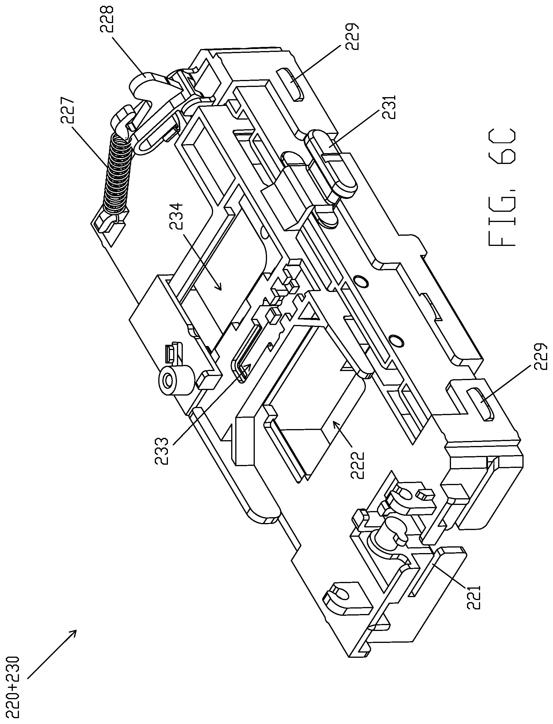
[0058] FIG. 6C illustrates yet another perspective view of main bracket 220 and test strip bracket 230 when test strip bracket 230 is in main bracket 220, according to some embodiments of the present disclosure. In conjunction of FIGS. 3A and 3B, test strip bracket 230 is maintained in a third state with respect to main bracket 220 so that main bracket 220 is neither aligned with first detecting opening 233 nor with second detecting opening 234. In some embodiments, in the third state, main detecting opening 222 is at least partially unobstructed from second door 226.
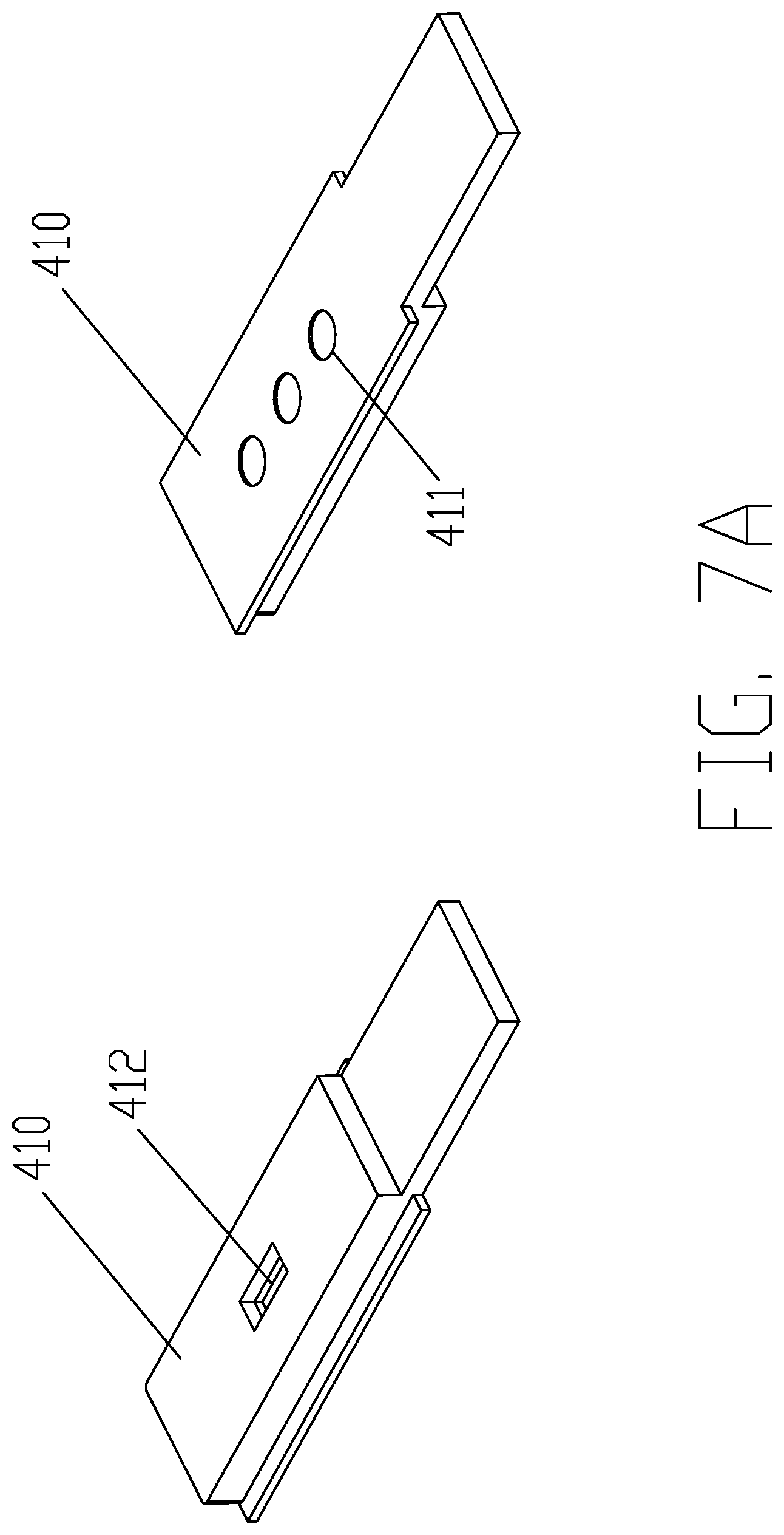
[0059] FIGS. 7A, 7B, 7C and 7D illustrate different type of test strips according to some embodiments of the present disclosure. FIG. 7A illustrates two perspective views of middle sized test strip 410. Middle sized test strip 410 may include multiple reaction areas 411 and sample collector 412. FIG. 7B illustrates two perspective views of small sized test strip 420. Small sized test strip 420 may include a reaction area 421 and a sample collector 422. FIG. 7C illustrates two perspective views of large sized test strip 440. Large sized test strip 440 may include reaction area 441 and sample collector 442. In some embodiments, a sample may be disposed in sample collectors 412, 422 and 442.
[0060] FIG. 7D illustrates two perspective views of calibration test strip 430. In some embodiments, calibration test strip 430 includes white calibration block 431, red color similar calibration blocks 432 and 433 (e.g., maroon calibration block and red calibration block) and green/blue color similar calibration blocks 434 and 435 (e.g., green calibration block and blue calibration block). A light to be used in illuminating the sample may be calibrated with calibration blocks 431, 432, 433, 434 and 435. In some embodiments, the red component included in the light may be calibrated by comparing one or more reflectance associated with red color similar calibration blocks 432 and 433 against one or more reflectance associated with white calibration block 431. In response to the comparison exceeding a predetermined range, the light (e.g., light from screen 320 of mobile device 300) is determined to be not suitable for illuminating the sample as the calibration result. Similarly, the green/blue components included in the light may be calibrated by comparing one or more reflectance associated with green/blue color similar calibration blocks 434 and 435 against one or more reflectance associated with white calibration block 431. In response to the comparison exceeding a predetermined range, the light is determined to be not suitable for illuminating the sample as the calibration result and another mobile device may be used to provide the light source instead of mobile device 300.
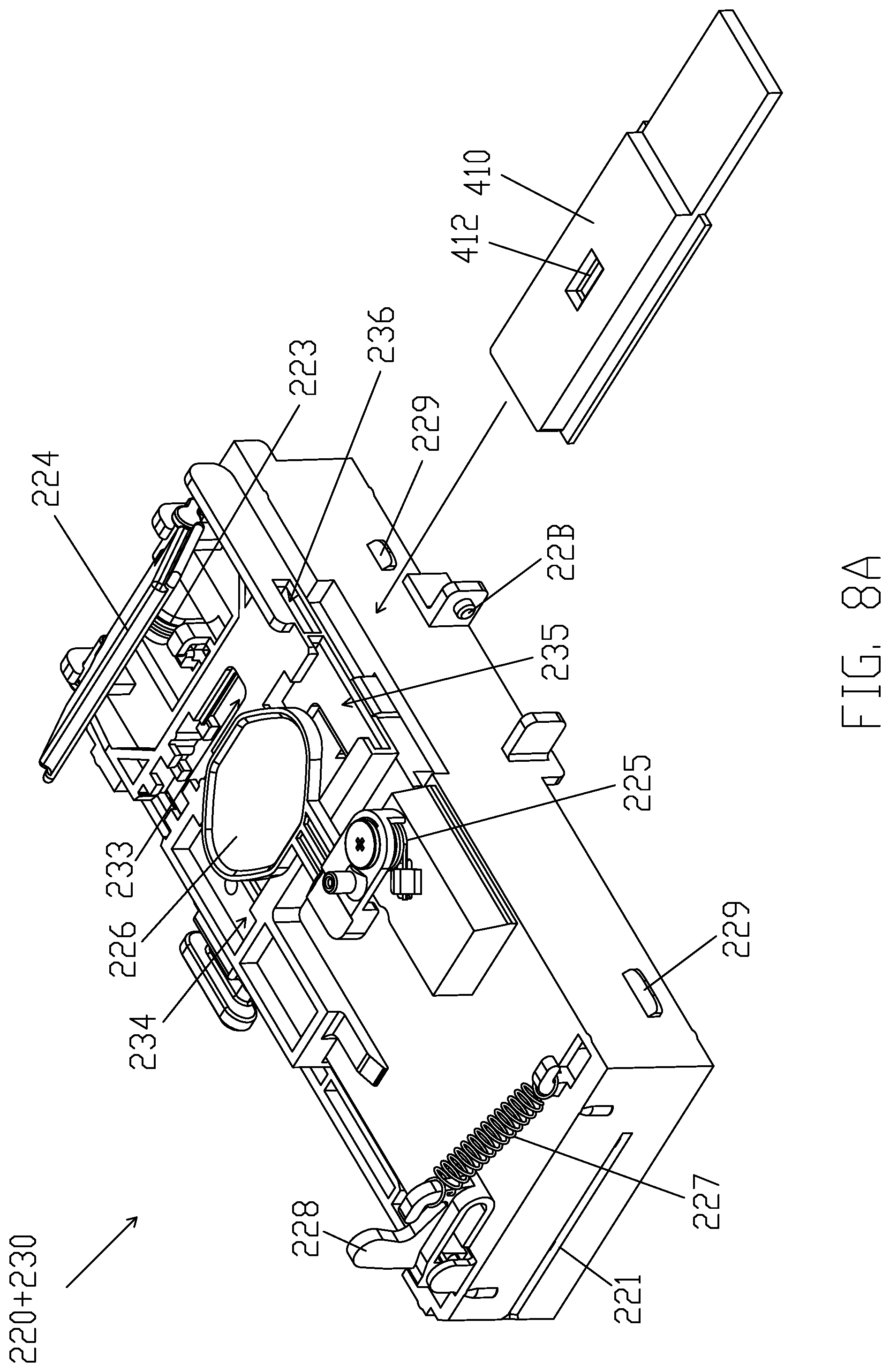
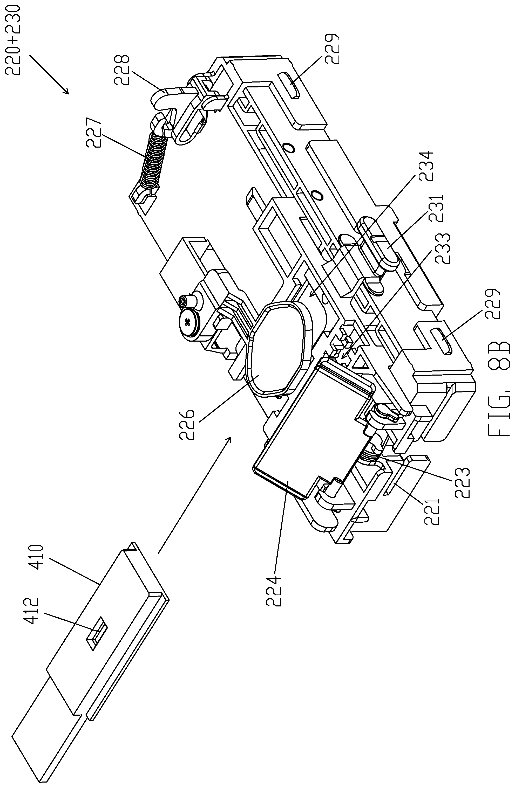
[0061] FIG. 8A illustrates front perspective view of main bracket 220 and test strip bracket 230 prior to middle sized test strip 410 being inserted into second detecting opening 234 and second inserting entry 215, according to some embodiments of the present disclosure. FIG. 8B illustrates back perspective view of main bracket 220 and test strip bracket 230 prior to middle sized test strip 410 being inserted into second detecting opening 234 and second inserting entry 215, according to some embodiments of the present disclosure. FIG. 8C illustrates front perspective view of main bracket 220 and test strip bracket 230 after middle sized test strip 410 being inserted into second detecting opening 234 and second inserting entry 215, according to some embodiments of the present disclosure. FIG. 8D illustrates back perspective view of main bracket 220 and test strip bracket 230 after middle sized test strip 410 being inserted into second detecting opening 234 and second inserting entry 215, according to some embodiments of the present disclosure.
[0062] In some embodiments, in conjunction with FIG. 3B, in response to middle sized test strip 410 being inserted into second inserting entry 215 (illustrated in FIG. 3B) and second detecting opening 234, middle sized test strip 410 may push second door 226 from the first position of second door 226 to the second position of second door 226 to reveal main detecting opening 222. Therefore, in conjunction with FIG. 6A, main detecting opening 222 is aligned with second detecting opening 234. In addition, entry 235 of second detecting opening 234 includes a first shape corresponding to second inserting entry 215 to receive middle sized test strip 410 and not test strips having different sizes from middle sized test strip 410.
[0063] In some embodiments, in response to middle sized test strip 410 being inserted into second inserting entry 215 and second detecting opening 234, reaction area 411 of middle sized test strip 410 is aligned with second detecting opening 234 and main detecting opening 222. In some embodiments, in conjunction with FIGS. 1, 2A, 3B and 3C, light from screen 320 is configured to pass through illuminating screen opening 112, light guide illuminating opening 242, main detecting opening 222 and second detecting opening 234 in sequence, and eventually illuminate reaction area 411. Camera 310 is also configured to capture images of reaction area 411 through second detecting opening 234, main detecting opening 222, light guide opening 241 and camera hole 111 in sequence. The capture images are then analyzed to obtain the concentration of an analyte (e.g., blood glucose) in the sample.
[0064] FIG. 9A illustrates front perspective view of main bracket 220 and test strip bracket 230 prior to small sized test strip 420 being inserted into first detecting opening 233 and second inserting entry 215, according to some embodiments of the present disclosure. FIG. 9B illustrates back perspective view of main bracket 220 and test strip bracket 230 prior to small sized test strip 420 being inserted into first detecting opening 233 and second inserting entry 215, according to some embodiments of the present disclosure. FIG. 9C illustrates front perspective view of main bracket 220 and test strip bracket 230 after small sized test strip 420 being inserted into first detecting opening 233 and second inserting entry 215, according to some embodiments of the present disclosure. FIG. 9D illustrates back perspective view of main bracket 220 and test strip bracket 230 after small sized test strip 420 being inserted into first detecting opening 233 and second inserting entry 215, according to some embodiments of the present disclosure.
[0065] In some embodiments, in conjunction with FIG. 3A, in response to small sized test strip 420 being inserted into second inserting entry 215 (illustrated in FIG. 3B) and first detecting opening 233, small sized test strip 420 may be placed underneath second door 226 and second door 226 is maintained at the first position of second door 226. Therefore, in conjunction with FIG. 6B, main detecting opening 222 is aligned with first detecting opening 233 free from the block of second door 226. In addition, entry 236 of third detecting opening 233 includes a second shape corresponding to second inserting entry 215 to receive small sized test strip 420 and not test strips having different sizes from small sized test strip 420
[0066] In some embodiments, in response to small sized test strip 420 being inserted into second inserting entry 215 and first detecting opening 233, reaction area 421 of small sized test strip 420 is aligned with first detecting opening 233 and main detecting opening 222. In some embodiments, in conjunction with FIGS. 1, 2A, 3A and 3C, light from screen 320 is configured to pass through illuminating screen opening 112, light guide illuminating opening 242, main detecting opening 222 and first detecting opening 233 in sequence, and eventually illuminate reaction area 421. Camera 310 is also configured to capture images of reaction area 421 through first detecting opening 233, main detecting opening 222, light guide opening 241 and camera hole 111 in sequence. The capture images are then analyzed to obtain the concentration of an analyte (e.g., blood glucose) in the sample.
[0067] FIG. 10A illustrates front perspective view of main bracket 220 and test strip bracket 230 prior to calibration test strip 430 being inserted into first inserting entry 214, according to some embodiments of the present disclosure. FIG. 10B illustrates back perspective view of main bracket 220 and test strip bracket 230 prior to calibration test strip 430 being inserted into first inserting entry 214, according to some embodiments of the present disclosure. FIG. 10C illustrates front perspective view of main bracket 220 and test strip bracket 230 after calibration test strip 430 being inserted into first inserting entry 214, according to some embodiments of the present disclosure. FIG. 10D illustrates back perspective view of main bracket 220 and test strip bracket 230 after calibration test strip 430 being inserted into first inserting entry 214, according to some embodiments of the present disclosure.
[0068] In some embodiments, in conjunction with FIG. 3A, in response to calibration test strip 430 being inserted into first inserting entry 214, calibration test strip 430 may push first door 224 and second door 226. By pushing second door 226 from the first position of second door 226 to the second position of second door 226, main detecting opening 222 is at least partially unobstructed from second door 226. In conjunction with FIG. 6C, a part of calibration test strip 430 (e.g., calibration blocks 431, 432, 433, 434 and 435) may be disposed above and aligned with main detecting opening 222.
[0069] In some embodiments, in conjunction with FIGS. 1, 2A, 3A and 3C, light from screen 320 is configured to pass through illuminating screen opening 112, light guide illuminating opening 242 and main detecting opening 222 in sequence, and eventually illuminate calibration blocks 431, 432, 433, 434 and 435 of calibration test strip 430. Camera 310 is also configured to capture images of calibration blocks 431, 432, 433, 434 and 435 through main detecting opening 222, light guide camera opening 241 and camera hole 111 in sequence. As set forth above, the capture images are then analyzed to determine whether light from screen 320 is a suitable light source for physiological measurement. In some embodiments, some example physiological measurements are illustrated in FIGS. 8A, 8B, 9A, 9B, 11A and 11B.
[0070] FIG. 11A illustrates front perspective view of main bracket 220 and test strip bracket 230 prior to large sized test strip 440 being inserted into first inserting entry 214, according to some embodiments of the present disclosure. FIG. 11B illustrates back perspective views of main bracket 220 and test strip bracket 230 prior to large sized test strip 440 being inserted into first inserting entry 214, according to some embodiments of the present disclosure. FIG. 11C illustrates front perspective view of main bracket 220 and test strip bracket 230 after large sized test strip 440 being inserted into first inserting entry 214, according to some embodiments of the present disclosure. FIG. 11D illustrates back perspective view of main bracket 220 and test strip bracket 230 after large sized test strip 440 being inserted into first inserting entry 214, according to some embodiments of the present disclosure.
[0071] In some embodiments, in conjunction with FIG. 3A, in response to large sized test strip 440 being inserted into first inserting entry 214, large sized test strip 440 may push first door 224 and second door 226. By pushing second door 226 from the first position of second door 226 to the second position of second door 226, main detecting opening 222 is at least partially unobstructed from second door 226. In conjunction with FIG. 6C, reaction area 442 of large sized test strip 440 may be disposed above and aligned with main detecting opening 222.
[0072] In some embodiments, in conjunction with FIGS. 1, 2A, 3A and 3C, light from screen 320 is configured to pass through illuminating screen opening 112, light guide illuminating opening 242 and main detecting opening 222 in sequence, and eventually illuminate reaction area 442 of large sized test strip 440. Camera 310 is also configured to capture images of reaction area 442 through main detecting opening 222, light guide camera opening 241 and camera hole 111 in sequence. The capture images are then analyzed to obtain the concentration of an analyte (e.g., blood glucose) in the sample.
[0073] As set forth above, in some embodiments, test strip adaptor 200 includes at least two inserting entries (e.g., first inserting entry 214 and second inserting entry 215) and at least three detecting opening (e.g., main detecting opening 222, first detecting opening 233, second detecting opening 234) to receive different types of test strips (e.g., test strips 410, 420, 430 and 440). There is no need for an user to change test strip adaptors to fit different types of test strips.
[0074] From the foregoing, it will be appreciated that various embodiments of the present disclosure have been described herein for purposes of illustration, and that various modifications may be made without departing from the scope and spirit of the present disclosure. Accordingly, the various embodiments disclosed herein are not intended to be limiting, with the true scope and spirit being indicated by the following claims.
* * * * *
D00000
D00001
D00002
D00003
D00004
D00005
D00006
D00007
D00008
D00009
D00010
D00011
D00012

D00013
D00014
D00015

D00016

D00017

D00018
D00019
D00020
D00021
D00022
D00023
D00024

D00025
D00026

D00027
D00028

D00029
D00030
D00031
D00032

D00033
XML
uspto.report is an independent third-party trademark research tool that is not affiliated, endorsed, or sponsored by the United States Patent and Trademark Office (USPTO) or any other governmental organization. The information provided by uspto.report is based on publicly available data at the time of writing and is intended for informational purposes only.
While we strive to provide accurate and up-to-date information, we do not guarantee the accuracy, completeness, reliability, or suitability of the information displayed on this site. The use of this site is at your own risk. Any reliance you place on such information is therefore strictly at your own risk.
All official trademark data, including owner information, should be verified by visiting the official USPTO website at www.uspto.gov. This site is not intended to replace professional legal advice and should not be used as a substitute for consulting with a legal professional who is knowledgeable about trademark law.