Backpack Vacuum Cleaner
Huang; Jian ; et al.
U.S. patent application number 16/999097 was filed with the patent office on 2020-12-03 for backpack vacuum cleaner. The applicant listed for this patent is Suzhou Premier Electrical Appliance Co., Ltd. Invention is credited to Jian Huang, Xinhua Wang.
| Application Number | 20200375421 16/999097 |
| Document ID | / |
| Family ID | 1000005047675 |
| Filed Date | 2020-12-03 |


| United States Patent Application | 20200375421 |
| Kind Code | A1 |
| Huang; Jian ; et al. | December 3, 2020 |
BACKPACK VACUUM CLEANER
Abstract
The present invention discloses a backpack vacuum cleaner, which includes a dust collection part, a base part, a vacuum electric fan and an air pressure alarm unit. The vacuum electric fan introduces dust-containing airflow into a dust collection bag from a dust inlet and guides air entering an exhaust space to an exhaust port. An air pressure detection element arranged in the tank detects the pressure in the exhaust space. The alarm sends an alarm signal to the outside and can decide whether to give an alarm to the outside based on a detection result of the air pressure detection element.
| Inventors: | Huang; Jian; (Suzhou, CN) ; Wang; Xinhua; (Suzhou, CN) | ||||||||||
| Applicant: |
|
||||||||||
|---|---|---|---|---|---|---|---|---|---|---|---|
| Family ID: | 1000005047675 | ||||||||||
| Appl. No.: | 16/999097 | ||||||||||
| Filed: | August 21, 2020 |
| Current U.S. Class: | 1/1 |
| Current CPC Class: | A47L 9/1683 20130101; A47L 5/36 20130101; A47L 9/22 20130101 |
| International Class: | A47L 5/36 20060101 A47L005/36; A47L 9/22 20060101 A47L009/22; A47L 9/16 20060101 A47L009/16 |
Claims
1. A backpack vacuum cleaner, comprising: a dust collection part comprising a tank with a dust inlet, wherein a dust collection container and a high-efficiency filter are mounted inside the tank, the dust collection container comprises a dust collection bag made of a breathable material, the high-efficiency filter is cylindrical and sleeved outside the dust collection bag, and an exhaust space is arranged between the high-efficiency filter and an inner wall surface of the tank; the dust inlet, the dust collection bag, the high-efficiency filter and the exhaust space are sequentially communicated; the tank comprises a tank body with a hollow internal structure and an openable tank cover mounted on the top of the tank body, and the dust inlet is arranged on the tank cover; a short air inlet pipe communicated with the dust inlet is arranged at the bottom of the tank cover and extends downwards from the dust inlet, and a tail end of the short air inlet pipe extends into the dust collection bag; a base part comprising a housing adjoining below the tank, an exhaust port communicated with the outside being arranged on the housing; a vacuum electric fan for introducing dust-containing airflow into the dust collection bag from the dust inlet and guiding air entering the exhaust space to the exhaust port; an air pressure alarm unit comprising an air pressure detection element arranged on the tank and used for detecting pressure in the exhaust space and an alarm used for sending an alarm signal to the outside, wherein the alarm can decide whether to send an alarm signal to the outside based on a detection result of the air pressure detection element; the air pressure detection element comprises an air pressure sensor, an air pressure processing chip and an air pressure sensing switch, the air pressure sensor detects the pressure in the exhaust space and outputs pressure data to the air pressure processing chip, and the air pressure processing chip outputs corresponding electrical signals to the air pressure sensing switch; and the air pressure sensing switch and the alarm are connected in series in an alarm circuit.
2. The backpack vacuum cleaner according to claim 1, wherein the alarm comprises a warning light and/or a buzzer arranged on the housing.
3. The backpack vacuum cleaner according to claim 1, wherein a hook is arranged on the tank body, a circumferential slot is arranged on an outer edge of the tank cover, and the tank cover is fixed to an upper part of the tank body by the hook being clamped in the slot.
4. The backpack vacuum cleaner according to claim 1, wherein a hole communicated with the exhaust space is formed in a wall of the tank, and the air pressure detection element is assembled at the hole.
5. The backpack vacuum cleaner according to claim 1, wherein the housing and the tank are integrally provided.
6. The backpack vacuum cleaner according to claim 1, wherein the vacuum electric fan comprises an impeller assembly and a motor for driving the impeller assembly to rotate to generate a negative pressure, the motor is arranged in the housing, and the impeller assembly is arranged in the tank and/or the housing.
7. The backpack vacuum cleaner according to claim 1, wherein the high-efficiency filter has a first vertical centerline extending in an up-down direction, and the dust collection bag has a second vertical centerline extending in the up-down direction, and the first vertical centerline coincides with the second vertical centerline.
8. The backpack vacuum cleaner according to claim 1, wherein the dust collection bag has a double-layer dust bag structure, the dust bag in an inner layer is a disposable paper dust bag that is easy to replace, and the dust bag in an outer layer is a cloth dust bag reusable after cleaning.
9. The backpack vacuum cleaner according to claim 8, wherein the cloth dust bag consists of two surface layers of non-woven fabrics and a cotton core sandwiched therebetween.
10. The backpack vacuum cleaner according to claim 1, wherein the high-efficiency filter comprises a cylindrical filter element which is circumferentially formed in a pleated and folded manner and a support member fixed on an outer side and/or an inner side of the cylindrical filter element.
11. The backpack vacuum cleaner according to claim 10, wherein the support member comprises a pair of cylindrical support meshes, and the cylindrical filter element in a pleated form is sandwiched between the pair of support meshes.
12. The backpack vacuum cleaner according to claim 11, wherein the support meshes are made of a stretched metal mesh.
13. The backpack vacuum cleaner according to claim 11, wherein the support meshes are edge-sealed and fixed at seams with smooth splicing strips.
14. The backpack vacuum cleaner according to claim 11, wherein the high-efficiency filter is further provided with a bottom cover fixed at the bottom of the support meshes, and the high-efficiency filter forms a cylindrical structure with an open upper part and a sealed lower part.
15. The backpack vacuum cleaner according to claim 8, wherein an upper end of the paper dust bag is provided with a mounting plate extending radially outward, each of the cloth dust bag and the high-efficiency filter is fixedly provided with a bezel at an upper edge, and sealing gaskets are also arranged between the bezel of the high-efficiency filter and the tank body, and between the bezel of the high-efficiency filter and the mounting plate of the paper dust bag.
16. The backpack vacuum cleaner according to claim 1, wherein an upper edge of the dust collection container and the upper edge of the high-efficiency filter are clamped and fixed between the tank cover and the tank body.
17. The backpack vacuum cleaner according to claim 1, further comprising a back-carrying system arranged on the tank and/or the housing and a rechargeable battery pack for supplying power to the vacuum electric fan.
Description
FIELD OF THE INVENTION
[0001] The invention relates to the technical field of cleaning apparatus, and in particular to a backpack vacuum cleaner.
BACKGROUND OF THE INVENTION
[0002] A traditional backpack vacuum cleaner usually includes a cleaner main body and a back-carrying device. The cleaner main body includes a housing, a dust bag and a dust shield (i.e., filter) arranged in the housing, and a suction motor. An air inlet and an air outlet are arranged on the housing. The dust bag is arranged outside the air inlet, the dust shield and the suction motor are arranged at the air outlet, and the air inlet, the dust bag, the dust shield, the air outlet and the suction motor are in airflow communication in sequence. Since the dust shield is arranged at the air outlet, the dust shield only has an effective filtering area equal to the cross-sectional area of the air outlet, the filtering area is small, the filtering efficiency is low, and the user needs to change the filter frequently to maintain a good cleaning effect. In addition, since the dust shield and the dust bag are separately arranged and occupy a certain space inside the housing, respectively, the dust collection volume of the dust bag is small, resulting in a relatively high replacement frequency of the dust bag, and bringing inconvenience for use by the users.
[0003] In addition, after a certain amount of dust is sucked by the vacuum cleaner, the air flow rate decreases, and the vacuuming efficiency decreases. Operators cannot feel the change in the effect immediately, and will continue to vacuum. In the same working time, the vacuuming efficiency of the vacuum cleaner decreases, and the workers need to increase the vacuuming time to meet the requirements of environmental cleaning standards, so repeated vacuuming will increase a lot of labor costs. Especially for workplaces with high dust-free requirements or high-risk nuclear environment, the labor cost will be higher.
SUMMARY OF THE INVENTION
[0004] In order to solve the above technical problems, it is an object of the present invention to provide a backpack vacuum cleaner with higher filtering efficiency and vacuuming efficiency.
[0005] In order to achieve the above purpose of the present invention, the present invention adopts the following technical scheme:
[0006] A backpack vacuum cleaner includes:
[0007] a dust collection part including a tank with a dust inlet, wherein a dust collection container and a high-efficiency filter are mounted inside the tank, the dust collection container includes a dust collection bag made of a breathable material, the high-efficiency filter is cylindrical and sleeved outside the dust collection bag, and an exhaust space is arranged between the high-efficiency filter and an inner wall surface of the tank; the dust inlet, the dust collection bag, the high-efficiency filter and the exhaust space are sequentially communicated; the tank includes a tank body with a hollow internal structure and an openable tank cover mounted on the top of the tank body, and the dust inlet is arranged on the tank cover; a short air inlet pipe communicated with the dust inlet is arranged at the bottom of the tank cover and extends downwards from the dust inlet, and a tail end of the short air inlet pipe extends into the dust collection bag;
[0008] a base part including a housing adjoining below the tank, an exhaust port communicated with the outside being arranged on the housing;
[0009] a vacuum electric fan for introducing dust-containing airflow into the dust collection bag from the dust inlet and guiding air entering the exhaust space to the exhaust port;
[0010] an air pressure alarm unit including an air pressure detection element arranged on the tank and used for detecting the pressure in the exhaust space and an alarm used for sending an alarm signal to the outside, wherein the alarm can decide whether to send an alarm signal to the outside based on a detection result of the air pressure detection element; the air pressure detection element includes an air pressure sensor, an air pressure processing chip and an air pressure sensing switch, the air pressure sensor detects pressure in the exhaust space and outputs pressure data to the air pressure processing chip, and the air pressure processing chip outputs corresponding electrical signals to the air pressure sensing switch; and the air pressure sensing switch and the alarm are connected in series in an alarm circuit.
[0011] In the above technical scheme, preferably, the alarm includes a warning light and/or a buzzer arranged on the housing.
[0012] In the above technical scheme, preferably, a hook is arranged on a tank body, a circumferential slot is arranged on an outer edge of the tank cover, and the tank cover is fixed to an upper part of the tank body by the hook being clamped in the slot.
[0013] In the above technical scheme, preferably, a hole communicated with the exhaust space is formed in a wall of the tank, and the air pressure detection element is assembled at the hole.
[0014] In the above technical scheme, preferably, the housing and the tank are integrally provided.
[0015] In the above technical scheme, preferably, the vacuum electric fan includes an impeller assembly and a motor for driving the impeller assembly to rotate to generate a negative pressure. The motor is arranged in the housing, and the impeller assembly is arranged in the tank and/or the housing.
[0016] In the above technical scheme, preferably, the high-efficiency filter has a first vertical centerline extending in an up-down direction, the dust collection bag has a second vertical centerline extending in the up-down direction, and the first vertical centerline coincides with the second vertical centerline.
[0017] In the above technical scheme, preferably, the dust collection bag has a double-layer dust bag structure. The dust bag in an inner layer is a disposable paper dust bag that is easy to replace, and the dust bag in an outer layer is a cloth dust bag reusable after cleaning.
[0018] In the above technical scheme, preferably, the cloth dust bag consists of two surface layers of non-woven fabrics and a cotton core sandwiched therebetween.
[0019] In the above technical scheme, preferably, the high-efficiency filter includes a cylindrical filter element which is circumferentially formed in a pleated and folded manner and a support member fixed on an outer side and/or an inner side of the cylindrical filter element.
[0020] In the above technical scheme, preferably, the support member includes a pair of cylindrical support meshes, and the cylindrical filter element in a pleated form is sandwiched between the pair of support meshes.
[0021] In the above technical scheme, preferably, the support meshes are made of a stretched metal mesh.
[0022] In the above technical scheme, preferably, the support meshes are edge-sealed and fixed at seams with smooth splicing strips.
[0023] In the above technical scheme, preferably, the high-efficiency filter is further provided with a bottom cover fixed at the bottom of the support meshes, and the high-efficiency filter forms a cylindrical structure with an open upper part and a sealed lower part.
[0024] In the above technical scheme, preferably, an upper end of the paper dust bag is provided with a mounting plate extending radially outward, each of the cloth dust bag and the high-efficiency filter is fixedly provided with a bezel at an upper edge, and sealing gaskets are also arranged between the bezel of the high-efficiency filter and the tank body, and between the bezel of the high-efficiency filter and the mounting plate of the paper dust bag.
[0025] In the above technical scheme, preferably, an upper edge of the dust collection container and the upper edge of the high-efficiency filter are clamped and fixed between the tank cover and the tank body.
[0026] In the above technical scheme, preferably, the backpack vacuum cleaner further includes a back-carrying system arranged on the tank and/or the housing and a rechargeable battery pack for supplying power to the vacuum electric fan.
[0027] The present invention has the beneficial effects that:
[0028] 1. By directly sleeving the high-efficiency filter outside the dust collection bag, on the one hand, the space utilization rate is improved through the sleeved structure, so that the effective filtering area of the high-efficiency filter is increased by times, thereby improving the air flow rate and prolonging the service life of the dust collection bag, and on the other hand, the high-efficiency filter is arranged upstream of the suction motor, and the air entering the suction motor has been purified, so that a motor room can be prevented from being polluted.
[0029] 2. By adding the air pressure alarm unit, a worker may set a working efficiency index of the vacuum cleaner as required (the air pressure is detected by the air pressure sensor, and a corresponding program is set inside the air pressure processing chip and a corresponding conversion into working efficiency index, for example an air flow rate of 20 L/S, is performed). When a certain amount of dust is sucked, the air flow rate of the vacuum cleaner drops to 20 L/S, and the vacuuming efficiency is lower than a lower limit index required by the worker. Therefore, the air pressure sensing switch of the vacuum cleaner will start to work and control the alarm to send out an alarm signal to remind the worker that the dust bag or filter needs to be replaced in time, so as to ensure that the vacuum cleaner operates in a high vacuuming efficiency state, thereby ensuring the working efficiency of the operators and reducing unnecessary labor waste.
[0030] 3. A short air inlet pipe communicated with the dust inlet is arranged at the bottom of the tank cover and extends downwards from the dust inlet, and a tail end of the short air inlet pipe extends into the dust bag, so that the short air inlet pipe can be conveniently connected with an external dust suction floor brush and other accessories, and the connection is more convenient. Furthermore, the short air inlet pipe is directly communicated with the dust inlet, so that when the short air inlet pipe is connected with the external dust suction floor brush and other accessories, it can be ensure that the dust accurately falls into the dust collection bag after entering from the dust inlet, and the vacuuming efficiency is further improved.
BRIEF DESCRIPTION OF THE DRAWINGS
[0031] FIG. 1 is a schematic perspective diagram of a backpack vacuum cleaner of the present invention, with a back-carrying system and a rechargeable battery pack omitted;
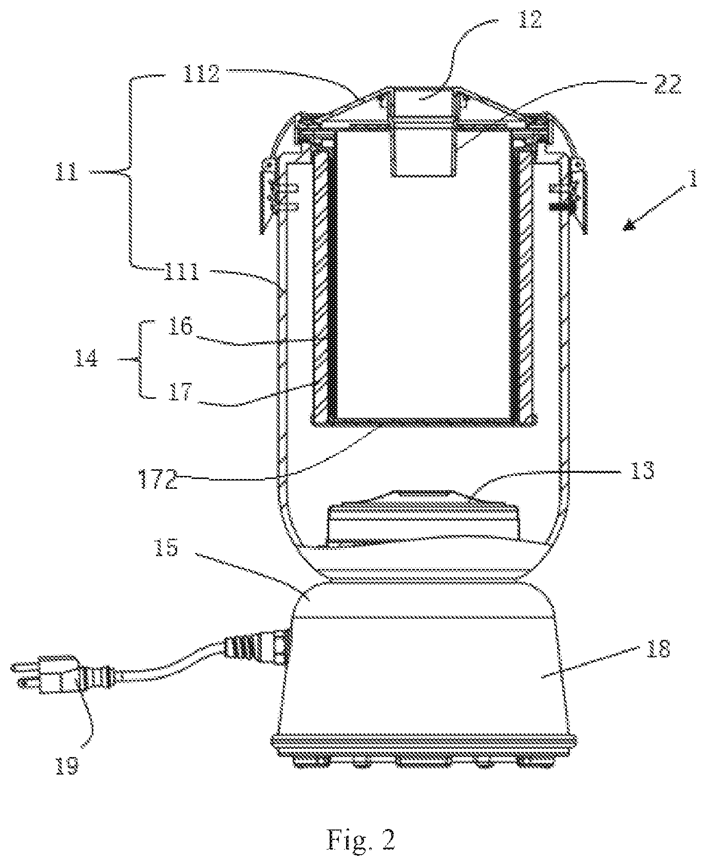
[0032] FIG. 2 is a schematic cross-sectional diagram of the inside of a tank of the backpack vacuum cleaner of the present invention;
[0033] FIG. 3 is a schematic diagram of a sleeved structure of a tank cover, a paper dust bag, a cloth dust bag and a high-efficiency filter of the backpack vacuum cleaner of the present invention;
[0034] FIG. 4 is a schematic front diagram of the high-efficiency filter of the present invention;
[0035] FIG. 5 is a schematic sectional diagram taken along A-A in FIG. 4;
[0036] FIG. 6 is an exploded schematic diagram of a dust collection container and the high-efficiency filter of the present invention;
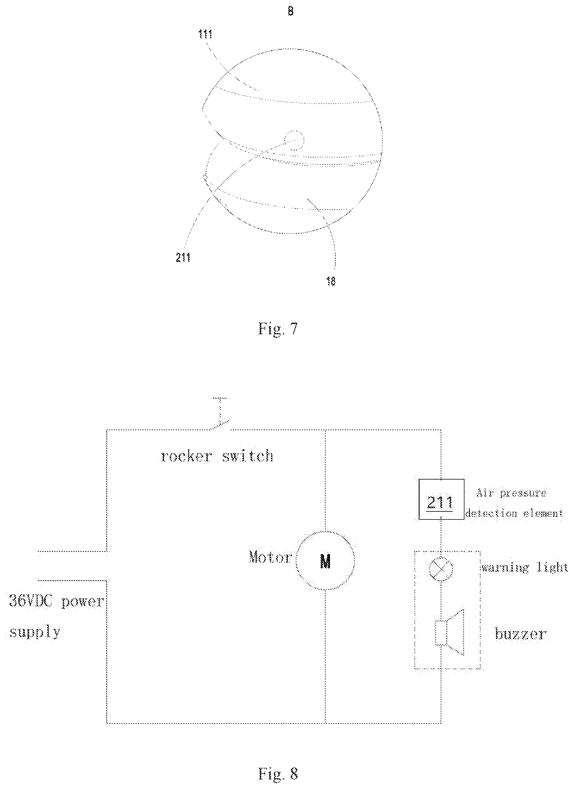
[0037] FIG. 7 is a partially enlarged schematic diagram of B shown in FIG. 1;
[0038] FIG. 8 is a schematic diagram of a circuit structure of an air pressure alarm unit of the present invention; and
[0039] FIG. 9 is a schematic diagram showing signal flow in an air pressure detection element of the present invention.
[0040] Reference numerals: 1, dust collection part; 11, tank; 111, tank body; 1111, hook; 112, tank cover; 1121, slot; 12, dust inlet; 13, air inlet; 14, dust collection container; 15, vacuum electric fan; 16, dust collection bag; 161, paper dust bag; 1611, mounting plate; 162, cloth dust bag; 17, high-efficiency filter; 171, support mesh; 172, bottom cover; 18, motor seat; 19, plug; 20, sealing gasket; 21, air pressure alarm unit; 211, air pressure detection element; 2111, air pressure sensor; 2112, air pressure processing chip; 2113, air pressure sensing switch; 212, alarm; and 22, short air inlet pipe.
DETAILED DESCRIPTION OF THE PREFERRED EMBODIMENT
[0041] In order to explain in detail the technical content, structural features, achieved objectives and effects of the present invention, the following will be described in detail in conjunction with embodiments and accompanying drawings.
[0042] The backpack vacuum cleaner includes a vacuum cleaner main body and a back-carrying system. The back-carrying system is fixedly connected with the vacuum cleaner main body, and typically has a structure including connecting structures such as a back strap and a shoulder strap, so that a user can carry the vacuum cleaner main body on the back. The vacuum cleaner has a power supply system which may be powered by batteries or connected with an external power supply. This section is the known knowledge and structure in the prior art, and will not be described in detail herein.
[0043] As shown in FIGS. 1-2, the vacuum cleaner main body includes a dust collection part 1, a base part 18, a vacuum electric fan 15 and an air pressure alarm unit 21.
[0044] The dust collection part 1 includes a tank 11 which includes a tank body 111 with an open upper portion and a tank cover 112 covering the upper portion of the tank body 111. The tank body 111 and the tank cover 112 are connected through a locking structure. Specifically, a hook 1111 is mounted on the tank body 111, and a circumferential slot 1121 is arranged at an outer edge of the tank cover 112. When in use, the tank cover 112 is fixed on an upper part of the tank body 111 by the hook 1111 being clamped in the slot 1121, so it is very convenient to assemble and disassemble the tank cover 112 with the tank body 111.
[0045] A dust inlet 12 is arranged on the tank cover 112. A short air inlet pipe 22 extending downward from the dust inlet 12 is provided. The tank body 111 is hollow inside.
[0046] The base part 18 includes a housing adjoining below the tank 11, and an exhaust port communicating with the outside is arranged on the housing. The housing is integrally provided with the tank 11.
[0047] The vacuum electric fan 15 is used to introduce dust-containing airflow into the dust collection bag 16 from the dust inlet 12 and guide air entering an exhaust space to the exhaust port. The vacuum electric fan is mounted on the base part 18 or in the tank body 111, and the air inlet 13 of the vacuum electric fan 15 and the dust inlet 12 are on a same axis. The base part 18 is provided with a plug 19 electrically connected with the vacuum electric fan 15, and the plug 19 may be electrically connected with the household commercial power through a transmission line such as a power strip. In order to facilitate the user's mobile vacuuming operation, a rechargeable battery pack electrically connected with the vacuum electric fan 15 may be arranged on the base part 18 or the back-carrying system instead of the plug 19. The vacuum electric fan 15 includes an impeller assembly and a motor which drives the impeller assembly to rotate to generate a negative pressure. The motor is arranged in the housing, and the impeller assembly is arranged in the tank 11. Of course, the impeller assembly may also be entirely arranged in the housing or partially extend into the tank.
[0048] As shown in FIG. 9, the air pressure alarm unit 21 includes an air pressure detection element 211 arranged on the tank 11 for detecting pressure in the exhaust space and an alarm 212 for sending an alarm signal to the outside. The air pressure detection element 211 includes an air pressure sensor 2111, an air pressure processing chip 2112 and an air pressure sensing switch 2113. The air pressure sensor 2111 detects the pressure in the exhaust space and outputs pressure data to the air pressure processing chip 2112, and the air pressure processing chip 2112 outputs corresponding electrical signals to the air pressure sensor switch 2113. The air pressure sensing switch 2113 and the alarm 212 are connected in series in an alarm circuit.
[0049] As shown in FIGS. 3-6, a dust collection container 14 and a high-efficiency filter 17 are mounted inside the tank 11.
[0050] The dust collection container 14 includes a dust collection bag 16 made of breathable material. The high-efficiency filter 17 is cylindrical and sleeved outside the dust collection bag 16, and the exhaust space is arranged between the high-efficiency filter 17 and an inner wall surface of the tank 11. The dust inlet 12, the dust collection bag 16, the high-efficiency filter 17 and the exhaust space are sequentially communicated. Specifically, the dust collection bag 16 has a double-layer dust bag structure. The dust bag in an inner layer is a disposable paper dust bag 161 that is easy to replace, and the dust bag in an outer layer is a cloth dust bag 162 reusable after cleaning. The paper dust bag 161 is usually a disposable paper bag made of a single-layer non-woven fabric and discardable after being filled with dust. The cloth dust bag 162 is a cloth dust bag consisting of two surface layers of non-woven fabrics and a cotton core sandwiched therebetween, so that the filtering effect is better. The paper dust bag 161 is sleeved inside the cloth dust bag 162. An upper end of the paper dust bag 161 is provided with a mounting plate 1611 extending radially outward. Each of the cloth dust bag 162 and the high-efficiency filter 17 is fixedly provided with a bezel at an upper edge. Sealing gaskets 20 are also arranged between the bezel of the high-efficiency filter 17 and the tank 111, and between the bezel of the high-efficiency filter 17 and the mounting plate 1611 of the paper dust bag 161.
[0051] At the same time, in the prior art, the internal filter and dust collection bag of the vacuum cleaner are separately arranged, so that such a design will have the problems of large occupied space and influence on filtering efficiency. In contrast, in this application, the sleeved structure of the high-efficiency filter 27 and the dust bag enables efficient space utilization and quick mounting and disassembly, so that the dust collection volume of the dust bag can be increased to a certain extent and the users do not need to change the dust collection bag 16 frequently, thereby meeting the daily use requirements of the users and increasing the convenience of the users.
[0052] When the dust collection container 14 is mounted by a user, the high-efficiency filter 17, the cloth dust bag 162 and the paper dust bag 161 are sequentially mounted on the tank body 111, and then the tank cover 112 is covered, and the short air inlet pipe 22 of the tank cover is made to extend into an opening of the paper dust bag 161. After that, the short air inlet pipe 22 and dust inlet 12 are connected with accessories such as a dust suction floor brush, the tank cover and the tank body 111 are tightly locked, and the mounting plate 1611 of the paper dust bag 161 and the bezels of the dust bag 162 and the high-efficiency filter 17 are tightly pressed and fixed between the tank cover and the tank body 111.
[0053] The short air inlet pipe 22 communicated with the dust inlet 12 is arranged at the bottom of the tank cover 112 and extends downward from the dust inlet 12, and a tail end of the short air inlet pipe 22 extends into the dust collection bag 16, so that the short air inlet pipe 22 can be conveniently connected with the external dust suction floor brush and other accessories, and the connection is more convenient. Furthermore, the short air inlet pipe 22 is directly communicated with the dust inlet 12, so that when the short air inlet pipe is connected with the external dust suction floor brush and other accessories, it can be ensured that the dust accurately falls into the dust collection bag 16 after entering from the dust inlet 12, and the vacuuming efficiency is further improved.
[0054] The high-efficiency filter 17 is sleeved on an outer peripheral side of the cloth dust bag 162. In this embodiment, the paper dust bag 162, the cloth dust bag 161 and the high-efficiency filter 17 are all cylindrical. The high-efficiency filter 17 has a first vertical centerline extending in an up-down direction, and the dust collection bag 16 has a second vertical centerline extending in the up-down direction, with the first vertical centerline coinciding with the second vertical centerline. Therefore, the effective filtering area of the high-efficiency filter 17 can be significantly increased, resulting in an improved filtering efficiency and cleaning effect.
[0055] The high-efficiency filter 17 includes a cylindrical filter element which is circumferentially formed in a pleated and folded manner and a support member fixed on an inner side of the cylindrical filter element. Specifically, the high-efficiency filter 17 is of a cylindrical structure with an open upper part and a sealed lower part. The supporting part includes a pair of cylindrical support meshes 171 each is formed by a stretched metal mesh that is butted into its self to form a cylindrical support structure. A bottom cover 172 is fixed at lower parts of the support meshes, and the cylindrical filter element in a pleated form is sandwiched between the pair of support meshes 171. That is, the pleated and folded filter element of the high efficiency particulate air filter (HEPA) is placed in a gap between the pair of support meshes. The pleated and folded filter element can maximize the filtering area and disperse dust. In order to prevent sharp burrs or bulges from being formed at seams of the stretched metal meshes to scratch the high-efficiency filter element or fingers of the users, the support meshes are edge-sealed and fixed at the seams with smooth plastic splicing strips. Of course, in other embodiments, the support member may also be arranged on an outer side of the cylindrical filter element, or both the inner and outer sides may be provided with support members to increase the support strength.
[0056] In operation, the dust-containing airflow enters the vacuum cleaner main body through the dust inlet 12 under the suction force of the vacuum electric fan 15. After the dust-containing airflow passes through the paper dust bag 161 and the cloth dust bag 162 in turn, most dust particles are collected in the paper dust bag 161, some fine dust is collected by the cloth dust bag 162, and a small amount of finer dust is collected by the high-efficiency filter 17. Finally, the filtered clean air is discharged from the air inlet 13 of the motor to the outside of the vacuum cleaner main body 1 through the air outlet after passing through a motor chamber. The paper dust bag 161, as a disposable article, may be discarded after being filled with dust. The cloth dust bag may be cleaned or replaced regularly. Thus, the high-efficiency filter in this utility model has a longer replacement period and can be used for a long time due to its significantly increased effective contact area.
[0057] In order to have a better filtering effect and improve the filtering effect of the high-efficiency filter, in other embodiments of the utility model, the high-efficiency filter may also be designed into a multi-layer filtering structure, or the bottom cover of the high-efficiency filter may be designed into the same filtering structure as its outer peripheral side wall, that is, the bottom cover of the high-efficiency filter can also be provided with a pleated high-efficiency filter element.
[0058] It should be noted that the dust filtering structure in the backpack vacuum cleaner described above, that is, the structure composed of the paper dust bag 162, the cloth dust bag 161 and the high-efficiency filter 17 sleeved outside the cloth dust bag 161, may also be applied to ordinary vacuum cleaners, such as hand-held vacuum cleaners or horizontal vacuum cleaners.
[0059] As shown in FIG. 1 and FIGS. 7-8, the alarm 212 includes a warning light and a buzzer arranged on the housing. A hole communicated with the exhaust space is formed in a wall of the tank 11, and the air pressure detection element 211 is mounted at the hole. The air pressure detection element 211 includes an air pressure sensor 2111, an air pressure processing chip 2112 and an air pressure sensing switch 2113. The air pressure sensor 2111 detects pressure in the exhaust space and outputs pressure data to the air pressure processing chip 2112, and the air pressure processing chip 2112 outputs corresponding electrical signals to the air pressure sensor switch 2113. The air pressure sensing switch 2113 and the alarm 212 are connected in series in an alarm circuit. By adding the air pressure alarm unit 212, a worker may set a working efficiency index of the vacuum cleaner as required (the air pressure is detected by the air pressure sensor 2111, and a corresponding program is set inside the air pressure processing chip 2112 and a corresponding conversion into working efficiency index, for example an air flow rate of 20 L/S, is performed). When a certain amount of dust is sucked, the air flow rate of the vacuum cleaner drops to 20 L/S, and the vacuuming efficiency is lower than a lower limit index required by the worker. Therefore, the air pressure sensing switch 2113 of the vacuum cleaner will start to work and control the alarm 212 to send out an alarm signal to remind the worker that the dust bag or filter needs to be replaced in time, so as to ensure that the vacuum cleaner operates in a high vacuuming efficiency state, thereby ensuring the working efficiency of the operators and reducing unnecessary labor waste.
[0060] The above embodiments are merely used for illustrating the technical concept and features of the present invention, and are intended to allow a person skilled in the art to understand the contents of the present invention and implement it accordingly, but not to limit the scope of protection of the present invention. All equivalent changes or modifications made according to the spirit of the present invention should be covered by the protection scope of the present invention.
* * * * *
D00000
D00001
D00002
D00003
D00004
D00005
D00006
D00007
XML
uspto.report is an independent third-party trademark research tool that is not affiliated, endorsed, or sponsored by the United States Patent and Trademark Office (USPTO) or any other governmental organization. The information provided by uspto.report is based on publicly available data at the time of writing and is intended for informational purposes only.
While we strive to provide accurate and up-to-date information, we do not guarantee the accuracy, completeness, reliability, or suitability of the information displayed on this site. The use of this site is at your own risk. Any reliance you place on such information is therefore strictly at your own risk.
All official trademark data, including owner information, should be verified by visiting the official USPTO website at www.uspto.gov. This site is not intended to replace professional legal advice and should not be used as a substitute for consulting with a legal professional who is knowledgeable about trademark law.