Sole Structure For Article Of Footwear
Strek; Kyle
U.S. patent application number 16/887395 was filed with the patent office on 2020-12-03 for sole structure for article of footwear. This patent application is currently assigned to NIKE, Inc.. The applicant listed for this patent is NIKE, Inc.. Invention is credited to Kyle Strek.
| Application Number | 20200375320 16/887395 |
| Document ID | / |
| Family ID | 1000004881423 |
| Filed Date | 2020-12-03 |


View All Diagrams
| United States Patent Application | 20200375320 |
| Kind Code | A1 |
| Strek; Kyle | December 3, 2020 |
SOLE STRUCTURE FOR ARTICLE OF FOOTWEAR
Abstract
An article of footwear is provided and includes an upper having a bottom surface and a first plate attached to the bottom surface of the upper in a forefoot region. The first plate includes a lateral peripheral cleat disposed adjacent to a first outward-most portion of the upper on a lateral side and a medial peripheral cleat disposed adjacent to a second outward-most portion of the upper on a medial side, the medial peripheral cleat being disposed closer to an anterior end of the first plate than the lateral peripheral cleat.
| Inventors: | Strek; Kyle; (Beaverton, OR) | ||||||||||
| Applicant: |
|
||||||||||
|---|---|---|---|---|---|---|---|---|---|---|---|
| Assignee: | NIKE, Inc. Beaverton OR |
||||||||||
| Family ID: | 1000004881423 | ||||||||||
| Appl. No.: | 16/887395 | ||||||||||
| Filed: | May 29, 2020 |
Related U.S. Patent Documents
| Application Number | Filing Date | Patent Number | ||
|---|---|---|---|---|
| 62855356 | May 31, 2019 | |||
| Current U.S. Class: | 1/1 |
| Current CPC Class: | A43B 5/025 20130101; A43C 15/162 20130101; A43C 15/161 20130101 |
| International Class: | A43C 15/16 20060101 A43C015/16 |
Claims
1. An article of footwear comprising: an upper having a bottom surface; a first plate attached to the bottom surface of the upper in a forefoot region and including a lateral peripheral cleat disposed adjacent to a first outward-most portion of the upper on a lateral side and a medial peripheral cleat disposed adjacent to a second outward-most portion of the upper on a medial side, the medial peripheral cleat being disposed closer to an anterior end of the first plate than the lateral peripheral cleat; and a first serrated region disposed between the lateral peripheral cleat and the medial peripheral cleat and including a plurality of elongate first ribs extending from a bottom surface of the first plate.
2. The article of footwear of claim 1, wherein the first outward-most portion of the upper and the second outward-most portion of the upper are aligned along a metatarsophalangeal axis.
3. The article of footwear of claim 1, wherein each of the peripheral cleats includes a stud disposed at the respective outward-most portion of the upper, a first blade extending along a first longitudinal direction from an anterior end of the stud, and a second blade extending along a second longitudinal direction from a posterior end of the stud.
4. The article of footwear of claim 3, wherein the stud includes an outward-facing surface disposed adjacent to a peripheral surface of the first plate.
5. The article of footwear of claim 1, wherein the first ribs of the plurality of elongate first ribs include an arcuate shape.
6. The article of footwear of claim 1, wherein the first ribs of the plurality of elongate first ribs include a concave surface formed on a first side of each first rib and a convex surface formed on an opposite side of each first rib.
7. The article of footwear of claim 6, wherein the concave surface of each first rib faces the anterior end of the first plate.
8. The article of footwear of claim 6, wherein the concave surface of each first rib faces a posterior end of the first plate.
9. The article of footwear of claim 1, further comprising a second serrated region disposed between the lateral peripheral cleat and the medial peripheral cleat and including a plurality of elongate second ribs extending from the bottom surface of the first plate.
10. The article of footwear of claim 9, wherein at least one first rib of the plurality of elongate first ribs includes a first concave surface and at least one second rib of the plurality of elongate second ribs includes a second concave surface, the first concave surface facing the anterior end of the first plate and the second concave surface facing a posterior end of the first plate.
11. An article of footwear comprising: an upper having a bottom surface; a first plate attached to the bottom surface of the upper in a forefoot region and including a first peripheral cleat disposed adjacent to a peripheral side surface of the first plate on a lateral side and a second peripheral cleat disposed adjacent to the peripheral side surface on a medial side, each of the first peripheral cleat and the second peripheral cleat (i) including a central stud and at least one blade extending in a longitudinal direction along the peripheral side surface of the first plate and (ii) being offset from one another along a longitudinal axis of the first plate; and a first serrated region disposed between the first peripheral cleat and the second peripheral cleat and including a plurality of elongate first ribs extending from a bottom surface of the first plate.
12. The article of footwear of claim 11, wherein the central stud and the at least one blade of the first peripheral cleat cooperate to form a first continuous outer surface adjacent to the peripheral side surface on the lateral side, and the central stud and the at least one blade of the second peripheral cleat cooperate to form a second continuous outer surface adjacent to the peripheral side surface on the medial side.
13. The article of footwear of claim 11, wherein the at least one blade includes a first blade extending along a first longitudinal direction from an anterior end of the central stud, and a second blade extending along a second longitudinal direction from a posterior end of the central stud.
14. The article of footwear of claim 13, wherein the central stud includes an outward-facing surface disposed adjacent to a peripheral surface of the first plate.
15. The article of footwear of claim 11, wherein the first ribs of the plurality of elongate first ribs include an arcuate shape.
16. The article of footwear of claim 11, wherein the first ribs of the plurality of elongate first ribs include a concave surface formed on a first side of each first rib and a convex surface formed on an opposite side of each first rib.
17. The article of footwear of claim 16, wherein the concave surface of each first rib faces an anterior end of the first plate.
18. The article of footwear of claim 16, wherein the concave surface of each first rib faces a posterior end of the first plate.
19. The article of footwear of claim 11, further comprising a second serrated region disposed between the first peripheral cleat and the second peripheral cleat and including a plurality of elongate second ribs extending from the bottom surface of the first plate.
20. The article of footwear of claim 19, wherein at least one first rib of the plurality of elongate first ribs includes a first concave surface and at least one second rib of the plurality of elongate second ribs includes a second concave surface, the first concave surface facing an anterior end of the first plate and the second concave surface facing a posterior end of the first plate.
Description
CROSS REFERENCE TO RELATED APPLICATIONS
[0001] This non-provisional U.S. Patent Application claims priority under 35 U.S.C. .sctn. 119(e) to U.S. Provisional Patent Application Ser. No. 62/855,356, filed May 31, 2019, the disclosure of which is hereby incorporated by reference in its entirety.
FIELD
[0002] The present disclosure relates generally to sole structures for articles of footwear and more particularly to sole structures incorporating traction elements.
BACKGROUND
[0003] This section provides background information related to the present disclosure which is not necessarily prior art.
[0004] Articles of footwear conventionally include an upper and a sole structure. The upper may be formed from any suitable material(s) to receive, secure, and support a foot on the sole structure. The upper may cooperate with laces, straps, or other fasteners to adjust the fit of the upper around the foot. A bottom portion of the upper, proximate to a bottom surface of the foot, attaches to the sole structure.
[0005] Sole structures generally include a layered arrangement extending between a ground surface and the upper. One layer of the sole structure includes an outsole that provides abrasion-resistance and traction with the ground surface. The outsole may be formed from rubber or other materials that impart durability and wear-resistance, as well as enhance traction with the ground surface. The outsole may include one or more traction elements or cleats for engaging a ground surface. Another layer of the sole structure includes a midsole disposed between the outsole and the upper. The midsole provides cushioning for the foot and may be partially formed from a polymer foam material that compresses resiliently under an applied load to cushion the foot by attenuating ground-reaction forces. Sole structures may also include a comfort-enhancing insole or a sockliner located within a void proximate to the bottom portion of the upper and a strobel attached to the upper and disposed between the midsole and the insole or sockliner.
DRAWINGS
[0006] The drawings described herein are for illustrative purposes only of selected configurations and are not intended to limit the scope of the present disclosure.
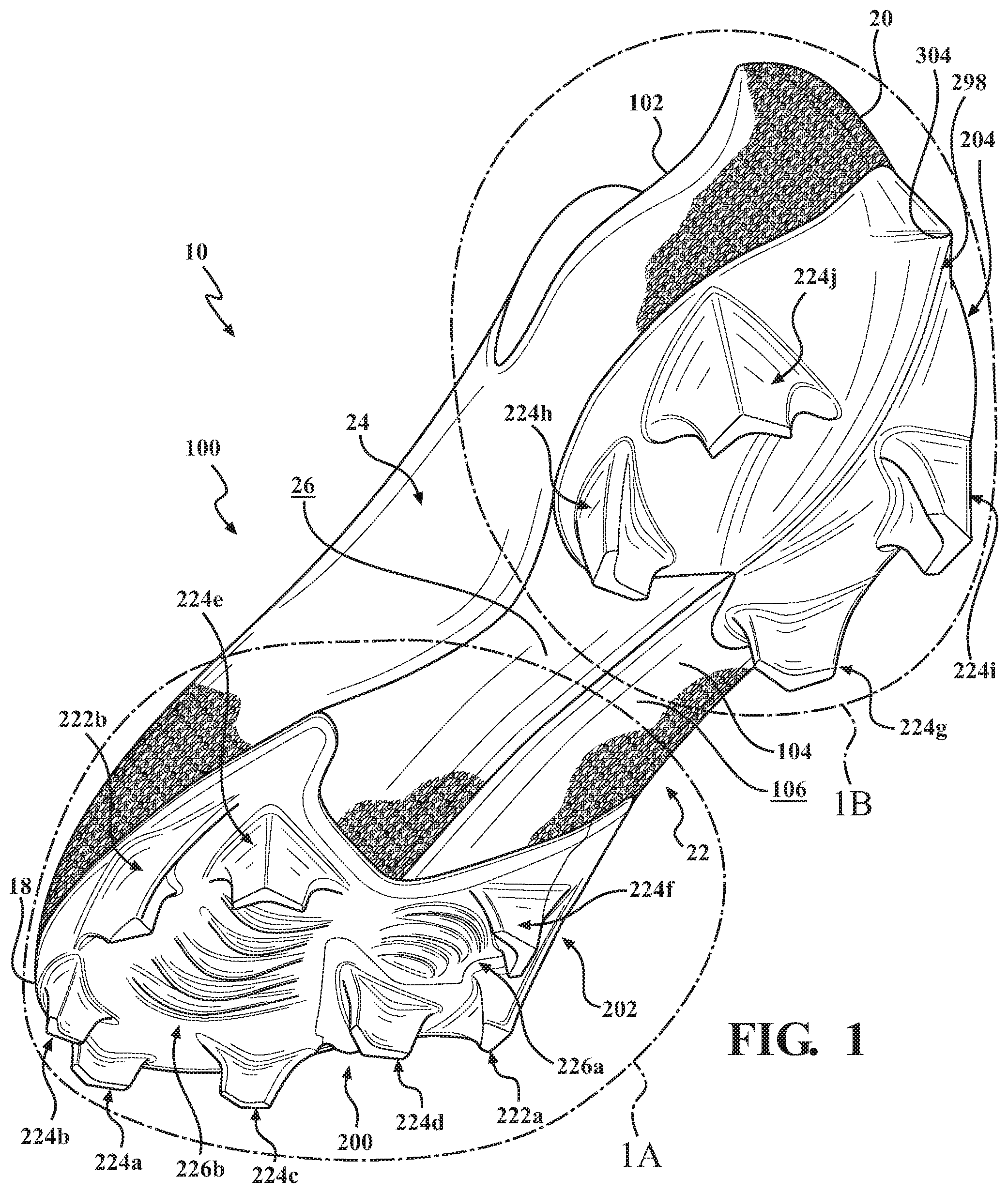
[0007] FIG. 1 is a bottom perspective view of an article of footwear in accordance with principles of the present disclosure;
[0008] FIG. 1A is an enlarged bottom perspective view of the article of footwear of FIG. 1, taken at area 1A in FIG. 1;
[0009] FIG. 1B is an enlarged bottom perspective view of the article of footwear of FIG. 1, taken at area 1B in FIG. 1;
[0010] FIG. 2 is a lateral side elevation view of the article of footwear of FIG. 1;
[0011] FIG. 3 is a medial side elevation view of the article of footwear of FIG. 1;
[0012] FIG. 4 is a front elevation view of the article of footwear of FIG. 1;
[0013] FIG. 5 is a rear elevation view of the article of footwear of FIG. 1;
[0014] FIG. 6 is a bottom plan view of the article of footwear of FIG. 1;
[0015] FIG. 6A is an enlarged bottom plan view of the article of footwear of FIG. 1, taken at area 6A of FIG. 6;
[0016] FIG. 6B is an enlarged bottom plan view of the article of footwear of FIG. 1, taken at area 6B of FIG. 6; and
[0017] FIG. 7 is a cross-sectional view of the article of footwear of FIG. 1, taken along section line 7-7 in FIG. 6.
[0018] Corresponding reference numerals indicate corresponding parts throughout the drawings.
DETAILED DESCRIPTION
[0019] Example configurations will now be described more fully with reference to the accompanying drawings. Example configurations are provided so that this disclosure will be thorough, and will fully convey the scope of the disclosure to those of ordinary skill in the art. Specific details are set forth such as examples of specific components, devices, and methods, to provide a thorough understanding of configurations of the present disclosure. It will be apparent to those of ordinary skill in the art that specific details need not be employed, that example configurations may be embodied in many different forms, and that the specific details and the example configurations should not be construed to limit the scope of the disclosure.
[0020] The terminology used herein is for the purpose of describing particular exemplary configurations only and is not intended to be limiting. As used herein, the singular articles "a," "an," and "the" may be intended to include the plural forms as well, unless the context clearly indicates otherwise. The terms "comprises," "comprising," "including," and "having," are inclusive and therefore specify the presence of features, steps, operations, elements, and/or components, but do not preclude the presence or addition of one or more other features, steps, operations, elements, components, and/or groups thereof. The method steps, processes, and operations described herein are not to be construed as necessarily requiring their performance in the particular order discussed or illustrated, unless specifically identified as an order of performance. Additional or alternative steps may be employed.
[0021] When an element or layer is referred to as being "on," "engaged to," "connected to," "attached to," or "coupled to" another element or layer, it may be directly on, engaged, connected, attached, or coupled to the other element or layer, or intervening elements or layers may be present. In contrast, when an element is referred to as being "directly on," "directly engaged to," "directly connected to," "directly attached to," or "directly coupled to" another element or layer, there may be no intervening elements or layers present. Other words used to describe the relationship between elements should be interpreted in a like fashion (e.g., "between" versus "directly between," "adjacent" versus "directly adjacent," etc.). As used herein, the term "and/or" includes any and all combinations of one or more of the associated listed items.
[0022] The terms first, second, third, etc. may be used herein to describe various elements, components, regions, layers and/or sections. These elements, components, regions, layers and/or sections should not be limited by these terms. These terms may be only used to distinguish one element, component, region, layer or section from another region, layer or section. Terms such as "first," "second," and other numerical terms do not imply a sequence or order unless clearly indicated by the context. Thus, a first element, component, region, layer or section discussed below could be termed a second element, component, region, layer or section without departing from the teachings of the example configurations.
[0023] In one configuration, an article of footwear is provided and includes an upper having a bottom surface and a first plate attached to the bottom surface of the upper in a forefoot region. The first plate includes a lateral peripheral cleat disposed adjacent to a first outward-most portion of the upper on a lateral side and a medial peripheral cleat disposed adjacent to a second outward-most portion of the upper on a medial side, the medial peripheral cleat being disposed closer to an anterior end of the first plate than the lateral peripheral cleat.
[0024] In one configuration, the first outward-most portion of the upper and the second outward-most portion of the upper may be aligned along a metatarsophalangeal axis. Additionally or alternatively, each of the peripheral cleats may include a stud disposed at the respective outward-most portion of the upper, a first blade extending along a first longitudinal direction from an anterior end of the stud, and a second blade extending along a second longitudinal direction from a posterior end of the stud. Optionally, the stud may include an outward-facing surface disposed adjacent to a peripheral surface of the first plate.
[0025] The first plate may include one or more serrated regions. The one or more serrated regions may include a first serrated region disposed on the lateral side of the first plate and a second serrated region disposed on the medial side of the first plate. Additionally or alternatively, each of the one or more serrated regions may include a plurality of arcuate ribs.
[0026] In one configuration, a second plate may be disposed in a heel region. Further, the first plate may include a plurality of directional cleats. Each of the directional cleats may include a first leg and a second leg.
[0027] In another configuration, an article of footwear is provided and includes an upper having a bottom surface and a first plate attached to the bottom surface of the upper in a forefoot region. The first plate includes a first peripheral cleat disposed adjacent to a peripheral side surface on a lateral side and a second peripheral cleat disposed adjacent to the peripheral side surface on a medial side, each of the first peripheral cleat and the second peripheral cleat (i) including a central stud and at least one blade extending in a longitudinal direction along the peripheral side surface of the first plate and (ii) being offset from one another along a longitudinal axis of the first plate.
[0028] In one configuration, the central stud and the at least one blade of the first peripheral cleat may cooperate to form a first continuous outer surface adjacent to the peripheral side surface on the lateral side, and the central stud and the at least one blade of the second peripheral cleat may cooperate to form a second continuous outer surface adjacent to the peripheral side surface on the medial side.
[0029] The at least one blade may include a first blade extending along a first longitudinal direction from an anterior end of the central stud, and a second blade extending along a second longitudinal direction from a posterior end of the central stud. The central stud may include an outward-facing surface disposed adjacent to a peripheral surface of the first plate.
[0030] In one configuration, the first plate may include one or more serrated regions. The one or more serrated regions may include a first serrated region disposed on the lateral side of the first plate and a second serrated region disposed on the medial side of the first plate. Each of the one or more serrated regions may include a plurality of arcuate ribs.
[0031] A second plate may be disposed in a heel region. Further, the first plate may include a plurality of directional cleats. Each of the directional cleats may include a first leg and a second leg.
[0032] Referring to FIGS. 1-3, an article of footwear 10 includes an upper 100 and a sole structure 200. The article of footwear 10 may be divided into one or more regions. The regions may include a forefoot region 12, a mid-foot region 14, and a heel region 16. The forefoot region 12 may be subdivided into a toe portion 12T corresponding with phalanges, and a ball portion 12B associated with metatarsal bones of a foot. A metatarsophalangeal (MTP) axis AMTP extends laterally across the article 10 along the intersection of the toe portion 12T and the ball portion 12B, and corresponds to an MTP joint of the foot. Accordingly, the article of footwear 10 is widest across the MTP axis AMTP. Put another way, outward-most portions of the article of footwear 10 are disposed on the MTP axis AMTP. The mid-foot region 14 may correspond with an arch area of the foot, and the heel region 16 may correspond with rear portions of the foot, including a calcaneus bone.
[0033] The footwear 10 may further include an anterior end 18 associated with a forward-most point of the forefoot region 12, and a posterior end 20 corresponding to a rearward-most point of the heel region 16. As shown in FIG. 6, a longitudinal axis A.sub.10 of the footwear 10 extends along a length of the footwear 10 from the anterior end 18 to the posterior end 20, parallel to a ground surface. The longitudinal axis A.sub.10 is centrally located along the length of the footwear 10, and generally divides the footwear 10 into a lateral side 22 and a medial side 24. Accordingly, the lateral side 22 and the medial side 24 respectively correspond with opposite sides of the footwear 10 and extend through the regions 12, 14, 16. As used herein, a longitudinal direction refers to the direction extending from the anterior end 18 to the posterior end 20, while a lateral direction refers to the direction transverse to the longitudinal direction and extending from the lateral side 22 to the medial side 24.
[0034] The upper 100 includes interior surfaces that define an interior void 102 configured to receive and secure a foot for support on the sole structure 200. An ankle opening in the heel region 16 may provide access to the interior void 102. For example, the ankle opening may receive a foot to secure the foot within the void 102 and to facilitate entry and removal of the foot from and to the interior void 102. The upper 100 may be formed from one or more materials that are stitched or adhesively bonded together to form the interior void 102. Suitable materials of the upper may include, but are not limited to, mesh, textiles, foam, leather, and synthetic leather. The materials may be selected and located to impart properties of durability, air-permeability, wear-resistance, flexibility, and comfort.
[0035] With reference to FIG. 7, in some examples the upper 100 includes a strobel 104 having a bottom surface 106 opposing the sole structure 200 and an opposing top surface 108 defining a footbed of the interior void 102. In some examples, the strobel 104 is attached to the upper 100 using stitching or adhesives. In the illustrated example, the upper 100 is formed as a unitary boot or sock, wherein the strobel 104 and the upper 100 are unitarily formed of a knitted material. The footbed defined by the top surface 108 may be contoured to conform to a profile of the bottom surface (e.g., plantar) of the foot. Optionally, the upper 100 may also incorporate additional layers such as one or more support plates 110, and an insole 112 or sockliner that may be disposed upon the strobel 104 and reside within the interior void 102 of the upper 100 to receive a plantar surface of the foot to enhance the comfort of the article of footwear 10.
[0036] In some examples, one or more fasteners extend along the upper 100 to adjust a fit of the interior void 102 around the foot and to accommodate entry and removal of the foot therefrom. The upper 100 may include apertures, such as eyelets and/or other engagement features such as fabric or mesh loops that receive the fasteners. The fasteners may include laces, straps, cords, hook-and-loop, or any other suitable type of fastener. The upper 100 may include a tongue portion that extends between the interior void 102 and the fasteners.
[0037] With continued reference to FIG. 1, the sole structure 200 is attached to the bottom surface 106 of the strobel 104 and includes a forefoot plate 202 disposed in the forefoot region 12 and a separate heel plate 204 disposed in the heel region 16. Accordingly, the mid-foot region 14 of the strobel 104 may be exposed between the forefoot plate 202 and the heel plate 204. As described in greater detail below, the forefoot plate 202 and the heel plate 204 each include a plurality of ground-engaging members, which are configured to engage a soft or resilient ground surface. Each of the forefoot plate 202 and the heel plate 204 are formed of one or more rigid or semi-rigid materials. In some examples, the forefoot plate 202 and the heel plate 204 are formed of one or more polymeric materials. In other examples, one or both of the forefoot plate 202 and the heel plate 204 may include a composite material, such as a fiber-reinforced composite material.
[0038] The forefoot plate 202 includes a top surface 206 (FIG. 7) attached to the bottom surface 106 of the upper 100, a bottom surface 208 formed on an opposite side of the forefoot plate 202 from the top surface 206, and a peripheral side surface 210 extending between the top surface 206 and the bottom surface 208 and defining an outer peripheral profile of the forefoot plate 202. Likewise, the heel plate 204 includes a top surface (not shown) attached to the bottom surface 106 of the upper 100, a bottom surface 214 formed on an opposite side of the forefoot plate 202 from the top surface, and a peripheral side surface 216 extending between the top surface and the bottom surface 208 and defining an outer peripheral profile of the heel plate 204. As discussed above, the forefoot plate 202 and the heel plate 204 are spaced apart from each other in the midfoot region 14 such that the bottom surface 106 of the upper 100 is exposed through the mid-foot region 14. Accordingly, the bottom surface 208 of the forefoot plate 202, the bottom surface 106 of the upper 100, and the bottom surface 214 of the heel plate 204 cooperate to define a ground-engaging surface 26 of the article of footwear 10.
[0039] As best shown in FIG. 6, the peripheral side surface 210 of the forefoot plate 202 includes a lateral portion 210a extending along the lateral side 22 of the upper 100 from the mid-foot region 14 to the anterior end 18, a medial portion 210b extending along the medial side 24 of the upper from the mid-foot region 14 to the anterior end 18, and a mid-foot portion 210c connecting the lateral portion 210a and the medial portion 210b across the mid-foot region 14.
[0040] In some examples, the lateral portion 210a of the peripheral side surface 210 may define a notch 218 on the lateral side 22 of the forefoot plate 202. The notch 218 is disposed in the toe portion 12T, intermediate the MTP axis AMTP and the anterior end 18. In some instances, the notch 218 extends inwardly from the lateral side 22 along a notch axis A.sub.218 formed at an oblique angle with respect to the longitudinal axis A.sub.10 of the footwear 10. As shown, the longitudinal axis A.sub.218 extends inwardly and towards the posterior end 20 of the footwear 10. Optionally, a width of the notch 218 may be tapered along the direction of the notch axis A.sub.218.
[0041] The mid-foot portion 210c of the peripheral side surface 210 may form a cut-out 220 at a posterior end of the forefoot plate 202, between the lateral portion 210a and the medial portion 210b. As shown, the cut-out 220 has a polygonal shape defined by a plurality of straight segments of the mid-foot portion 210c. In other examples, the cut-out 220 may be arcuate, or a combination of arcuate and polygonal.
[0042] The bottom surface 208 of the forefoot plate 202 includes a plurality of traction elements including a pair of peripheral traction elements 222a, 222b and one or more directional traction elements 224a-224f In some examples, the forefoot plate 202 may further include at least one serrated region 226a, 226b formed in an interior portion of the bottom surface 208.
[0043] The peripheral traction elements 222a, 222b include a lateral peripheral traction element 222a disposed adjacent to an outward-most portion of the article of footwear 10 on the lateral side 22, and a medial peripheral traction element 222b disposed adjacent to an outward-most portion of the article of footwear 10 on the medial side 22. Accordingly, the lateral peripheral traction element 222a and the medial peripheral traction element 222b are aligned with each other along the MTP axis A.sub.218, such that the peripheral traction elements 222a, 222b are disposed on opposite sides of the widest portion of the footwear 10. Thus, the lateral peripheral traction element 222a is disposed adjacent to an outward-most portion of the upper 100 on the lateral side 22 of the forefoot plate 202, while the medial peripheral traction element 222b is disposed adjacent to an outward-most portion of the upper 100 on the medial side 24 of the forefoot plate 202. The medial peripheral traction element 222b may be offset from the lateral peripheral traction element 222a along the longitudinal axis A.sub.10 such that the medial peripheral traction element 222b is disposed closer to the anterior end 18 than the lateral peripheral traction element 222a, as shown in FIG. 6.
[0044] Each of the peripheral traction elements 222a, 222b includes a central stud 228a, 228b, an anterior blade 230a, 230b extending from the central stud 228a, 228b towards the anterior end 18, and a posterior blade 232a, 230b extending in an opposite direction from the central stud 228a, 228b towards the posterior end 20. The central stud 228a, 228b extends from a proximal end 234a, 234b attached to the bottom surface 208 to a terminal, distal end 236a, 236b facing away from the bottom surface 208.
[0045] In the illustrated example, each of the central studs 228a, 228b includes an outer surface 238a, 238b, a posterior surface 240a, 240b, and an inner surface 242a, 242b that cooperate to define a substantially triangular cross-sectional shape of each of the central studs 228a, 228b. One or both of the central studs 228a, 228b may taper along a direction from the proximal end 234a, 234b to the distal end 236a, 236b, whereby a cross-sectional area of the distal end 236a, 236b is less than a cross-sectional area of the proximal end 234a, 234b. The outer surfaces 238a, 238b of each of the studs 228a, 228b extend from the peripheral side surface 210 of the forefoot plate 202 such that the central studs 228a, 228b form a portion of the outer peripheral of the forefoot plate 202. Optionally, the posterior surface 232b of the central stud 228b on the medial side 24 may be concave, while the posterior surface 232a of the central stud 228a on the lateral side 22 is substantially planar.
[0046] As best shown in FIG. 6A, each of the anterior blades 230a, 230b includes a first end 244a, 244b attached to an anterior end of the central stud 228a, 228b and a terminal end 246a, 246b disposed between the central stud 228a, 228b and the anterior end 18. Accordingly, a length of each of the anterior blades 230a, 230b extends from the first end 244a, 244b at the central stud 228, and towards the anterior end 18 of the article of footwear 10 to the terminal end 246a, 246b.
[0047] A height of the anterior blades 230a, 230b extends from a base 248a, 248b attached to the bottom surface 208 of the forefoot plate 202 to a distal edge 250a, 250b facing away from the bottom surface 208. As shown in FIGS. 2 and 3, the heights of the anterior blades 230a, 230b taper along the lengthwise direction of each of the anterior blades 230a, 230b, from the first end 244a, 244b to the terminal end 246a, 246b. In some examples, the distal edge 250a, 250b may have a concave profile from the first end 244a, 244b to the terminal end 246a, 246b.
[0048] In the illustrated example, each of the anterior blades 230a, 230b includes an outer surface 252a, 252b facing an outer periphery of the article 10, and an inner surface 254a, 254b formed on an opposite side of the anterior blade 230a, 230b from the outer surface 252a, 252b. The outer surface 252a, 252b and the inner surface 254a, 254b may converge with each other in the lengthwise direction from the first end 244a, 244b to the terminal end 246a, 246b. Additionally or alternatively, the outer surface 252a, 252b and the inner surface 254a, 254b may converge with each other in the height direction from the base 248a, 248b to the distal edge 250a, 250b. Accordingly, widths of the anterior blades 230a, 230b taper along the length direction and the height direction. As shown, the outer surface 252a, 252b and the inner surface 254a, 254b intersect with each other at the distal edge 250a, 250b, such that the distal edge 250a, 250b forms a sharp edge extending continuously from the first end 244a, 244b to the terminal end 246a, 246b.
[0049] Referring still to FIG. 6A, each of the posterior blades 232a, 232b includes a first end 256a, 256b attached to an posterior end of the central stud 228a, 228b and a terminal end 258a, 258b disposed between the central stud 228a, 228b and the posterior end 20 in the forefoot region 12. Accordingly, a length of each of the posterior blades 232a, 232b extends from the first end 256a, 256b at the central stud 228, and towards the posterior end 20 of the article of footwear 10 to the terminal end 258a, 258b.
[0050] A height of the posterior blades 232a, 232b extends from a base 260a, 260b attached to the bottom surface 208 of the forefoot plate 202 to a distal edge 262a, 262b facing away from the bottom surface 208. As shown in FIGS. 2 and 3, the heights of the posterior blades 232a, 232b taper along the lengthwise direction of each of the posterior blades 232a, 232b, from the first end 256a, 256b to the terminal end 258a, 258b. In some examples, the distal edge 262a, 262b may have a concave profile from the first end 256a, 256b to the terminal end 258a, 258b.
[0051] In the illustrated example, each of the posterior blades 232a, 232b includes an outer surface 264a, 264b facing an outer periphery of the article of footwear 10, and an inner surface 266a, 266b formed on an opposite side of the posterior blade 232a, 232b from the outer surface 264a, 264b. The outer surface 264a, 264b and the inner surface 266a, 266b may converge with each other in the lengthwise direction from the first end 256a, 256b to the terminal end 258a, 258b. Additionally or alternatively, the outer surface 264a, 264b and the inner surface 266a, 266b may converge with each other in the height direction from the base 260a, 260b to the distal edge 262a, 262b. Accordingly, widths of the posterior blades 232a, 232b may taper along the length direction and the height direction. As shown, the outer surface 264a, 264b and the inner surface 266a, 266b intersect with each other at the distal edge 262a, 262b, such that the distal edge 262a, 262b forms a sharp, knife-like edge extending continuously from the first end 256a, 256b to the terminal end 258a, 258b.
[0052] The outer surfaces 238a, 252a, 264a of the lateral peripheral cleat 222a are continuously formed with each other, and cooperate to form a substantially continuous convex surface facing the lateral portion 210a of the outer peripheral side surface 210. Likewise, the outer surfaces 238b, 252b, 264b of the medial peripheral cleat 222b are continuously formed with each other, and cooperate to form a substantially continuous convex surface facing the medial portion 210b of the peripheral side surface 210.
[0053] The inner surfaces 254a, 254b of the anterior blades 230a, 230b intersect the inner surfaces 240a, 240b of the respective central studs 228a, 228b to form substantially continuous convex surfaces at anterior portions of the peripheral cleats 222a, 222b. Similarly, the inner surfaces 264a, 264b of the posterior blades 232a, 232b intersect the posterior surfaces 242a, 242b of the respective central studs 228a, 228b to form substantially continuous convex surfaces at posterior portions of the peripheral cleats 222a, 222b.
[0054] On the lateral peripheral cleat 222a, the intersection between the inner surface 254a of the anterior blade 230a and the inner surface 240a of the central stud 228a has a first radius R.sub.230a, while the intersection between the inner surface 266a of the posterior blade 232a and the posterior surface 242a of the central stud 228a has a second radius R.sub.232a. Optionally, the first radius R.sub.230a may be larger than the second radius R.sub.232a such that a transition from the inner surface 254a of the anterior blade 230a and the inner surface 240a of the central stud 228a is more gradual than the transition from the inner surface 266a of the posterior blade 232a and the posterior surface 242a of the central stud 228a.
[0055] On the lateral peripheral cleat 222b, the intersection between the inner surface 254b of the anterior blade 230b and the inner surface 240b of the central stud 228b has a first radius R.sub.230b, while the intersection between the inner surface 266b of the posterior blade 232b and the posterior surface 242b of the central stud 228b has a second radius R.sub.232b. Optionally, the first radius R.sub.230b may be larger than the second radius R.sub.232b such that a transition from the inner surface 254b of the anterior blade 230b and the inner surface 240b of the central stud 228b is more gradual than the transition from the inner surface 266b of the posterior blade 232b and the posterior surface 242b of the central stud 228b.
[0056] As shown in FIG. 6A, the distal edges 250a, 262a of the lateral peripheral cleat 222a extend substantially parallel to the curvature of the lateral portion 210a of the peripheral side surface. The distal edges 250b, 262b of the medial peripheral cleat 222b may extend at an oblique angle relative to the peripheral side surface 210. For example, the distal edges 250b, 262b of the anterior blade 230b and the posterior blade 232b may diverge from the peripheral side surface 210 along the lengthwise direction from the first end 244b, 256b to the terminal end 246b, 258b.
[0057] In addition to the peripheral cleats 222a, 222b, the forefoot plate 202 includes one or more directional cleats 224a-224f Each of the directional cleats 224a-224f extends from a base 268a-268f attached to the bottom surface 208 of the forefoot plate 202 to a distal tip 270a-270f facing away from the bottom surface 208, as best shown in FIG. 1A. In some examples, the distal tip 270a-270f is substantially planar.
[0058] Each of the directional cleats 224a-224f has a generally chevron-shaped configuration including a first leg 272a-272f and a second leg 274a-274f extending in opposite directions from a central portion 276a-276f to respective distal ends. However, the size and/or shape of one or more of the directional cleats 224a-224f may transition along the direction from the base 268a-268f to the distal tip 270a-270f For example, the directional cleats 224a-224f may be tapered from the base 268a-268f to the distal tip 270a-270f Additionally or alternatively, the cross-sectional shape of one or more of the directional cleats 224a-224f may transition from a chevron having rounded sides at the base 268a-268f to a chevron having straight sides at the distal tip 270a-270f.
[0059] As shown, the first leg 272a-272f and the second leg 274a-274f cooperate to define a convex or pointed leading face 278a-278f and a concave or cupped trailing face 280a-280f formed on an opposite side of the directional cleat 224a-224f from the leading face 278a-278f. In some examples, the leading face 278a-278f may include a leading edge formed along the central portion 276a-276f from the base 268a-268f to the tip 270a-270f.
[0060] With continued reference to FIG. 6A, the forefoot plate 202 includes a first directional cleat 224a located adjacent to the anterior end 18 of the sole structure 200, with the leading face 278a facing towards the anterior end 18. A second directional cleat 224b is located in the toe portion 12T adjacent to the medial portion 210b of the peripheral side surface 210. A third directional cleat 224c is located in the toe portion 12T, laterally across from the second directional cleat 224b and adjacent to the lateral portion 210a of the peripheral side surface 210. More particularly, the second directional cleat 224b is located adjacent to and forward of (i.e., towards the anterior end 18) the notch 218, with the leading face 278b oriented forward and towards the lateral side 22. A fourth directional cleat 224d is located in the toe portion 12T on the lateral side 22, adjacent to the anterior blade 230a of the lateral peripheral cleat 222a. The leading face 278d of the fourth directional cleat 224d is oriented towards the anterior end 18.
[0061] In addition to the substantially forward-facing directional cleats 224a-224d described above, the forefoot plate may include fifth and sixth directional cleats 224e, 224f located in the ball portion 12B Particularly, the fifth directional cleat 224e is disposed in the ball portion 12B on the medial side 24 of the forefoot plate 202, adjacent to the posterior blade 232b of the medial peripheral cleat 222b. Here, the leading face 278e of the fifth directional cleat 224e is oriented rearward (i.e., towards the posterior end 20) and towards the medial side 24. The sixth directional cleat 224f is positioned on the lateral side of the ball portion 12B, adjacent to the posterior blade 232a of the lateral peripheral cleat 222a. Here, the leading face 278f of the sixth directional cleat 224f is oriented rearward and towards the lateral portion 210a of the peripheral side surface 210.
[0062] The forefoot plate 202 may also include one or more serrated regions 226a, 226b formed on an interior portion of the bottom surface 208. Each of the serrated regions 226a, 226b includes a plurality of elongate ribs 282a, 282b arranged in series along a direction of the longitudinal axis A.sub.10. A length of each of the ribs 282a, 282b extends continuously from a first end 284a, 284b to a second end 286a, 286b, while a height of each of the ribs 282a, 282b extends from the bottom surface 208 of the forefoot plate to a distal edge 288a, 288b. In some examples, the height of each of the ribs 282a, 282b tapers along the length from a central portion to at least one of the first end 284a, 284b and the second end 286a, 286b, whereby a height of each rib 282a, 282b is greater in the middle. Particularly, the height of the ribs 282a, 282b may taper continuously to each end 284a, 284b, 286a, 286b so that the distal edge 288a, 288b intersects the bottom surface 208 of the forefoot plate 202.
[0063] Optionally, the length of each of the ribs 282a, 282b may extend along an arcuate path and include a concave inner surface 290a, 290b and a convex outer surface 292a, 292b. Here, adjacent ones of the ribs 282a, 282b may be substantially parallel to provide a series of arcuate ribs 282a, 282b arranged along the bottom surface 208. Optionally, lengths of successive ones of the ribs 282a, 282b may progressively increase from a first end (facing the concave inner surfaces) of the serrated region 226a, 226b to a second end (facing the convex outer surfaces) of the serrated region 226a, 226b. Accordingly, lengths of ribs 282a, 282b closer to the first end of the serrated region 226a, 226b will be shorter than ribs 282a, 282b closer to the second end of the serrated region 226a, 226b. Put another way, the serrated regions 226a, 226b may be described as having an overall width that tapers along the direction from the first end to the second end, whereby the lengths of the ribs 282a, 282b become successively shorter.
[0064] In the illustrated example, a first serrated region 226a is positioned on the lateral side 22 of the forefoot plate 202 in the ball portion 12B. As best shown in FIG. 6A, the first serrated region 226a is positioned adjacent to the trailing face 280f of the sixth directional cleat 224f and an inside edge of the central stud 228a of the lateral peripheral cleat 222a. The first serrated region 226a is also disposed between the trailing face 280f of the sixth directional cleat 224f and the trailing face 280d of the fourth directional cleat 224d. Here, the concave inner surfaces 290a of the ribs 282a face the anterior end of the forefoot plate 202. Accordingly, an overall width (i.e. lengths of the ribs 282a) of the first serrated region 226a tapers along the direction from the posterior end 20 to the anterior end 18.
[0065] A second serrated region 226b is positioned on the medial side 24 of the forefoot plate 202 and extends from a first end in the ball portion 12B to a second end in the toe portion 12T. Here, the first end is disposed adjacent to the trailing face 280e of the fifth directional traction element 224e and the second end is adjacent to the second directional traction element 224b and the third directional traction element 224c. Accordingly, an overall width (i.e. lengths of the ribs 282b) of the second serrated region 226b tapers along the direction from the anterior end 18 to the posterior end 20.
[0066] The heel plate 204 of the sole structure 200 is located in the heel region 16 adjacent to the posterior end 20. The peripheral side surface 216 of the heel plate 204 may define a notch 294 in an anterior end of the heel plate 204, which divides the anterior end of the heel plate 204 into lateral and medial lobes 296a, 296b. The notch 294 tapers in width from the anterior end of the heel plate 204 to a central portion of the heel plate 204.
[0067] The heel plate 204 includes a central spine 298 extending from a first end 300 at the notch 294 to a second end 302 at the posterior end 20 of the article of footwear 10 along the longitudinal axis A.sub.10. The spine 298 may include a cleat 304 formed in an intermediate portion thereof. In some examples, the cleat 304 is formed where a first portion 298a of the spine 298 that extends longitudinally along the bottom surface 214 of the heel plate 204 intersects a second portion 298b of the spine 298 that extends vertically along the posterior end 20 of the heel plate 204. Here, a thickness of the first portion 298a continuously increases along a direction from the first end 300 of the spine 298 and a thickness of the second portion 298b continuously increases along a direction from the second end 302 of the spine 298. Accordingly, the cleat 304 is formed at the thickest portion of the spine 298, where the first portion 298a and the second portion 298b converge.
[0068] As with the forefoot plate 202, the heel plate 204 includes one or more directional cleats 224g-224j. Each of the directional cleats 224g-224j extends from a base 268g-268j attached to the bottom surface 208 of the forefoot plate 202 to a distal tip 270g-270j facing away from the bottom surface 208, as best shown in FIG. 1B. In some examples, the distal tip 270g-270j is substantially planar.
[0069] Each of the directional cleats 224g-224j has a generally chevron-shaped configuration including a first leg 272g-272j and a second leg 274g-274j extending in opposite directions from a central portion 276g-276j to respective distal ends. However, the size and/or shape of one or more of the directional cleats 224g-224j may transition along the direction from the base 268g-268j to the distal tip 270g-270j. For example, the directional cleats 224g-224j may be tapered from the base 268g-268j to the distal tip 270g-270j. Additionally or alternatively, the cross-sectional shape of one or more of the directional cleats 224g-224j may transition from a chevron having rounded sides at the base 268g-268j to a chevron having straight sides at the distal tip 270g-270j.
[0070] As shown, the first leg 272g-272j and the second leg 274g-274j cooperate to define a convex or pointed leading face 278g-278j and a concave or cupped trailing face 280g-280j formed on an opposite side of the directional cleat 224g-224j from the leading face 278g-278j. In some examples, the leading face 278g-278j may include a leading edge formed along the central portion 276a-276j from the base 268g-268j to the tip 270g-270j.
[0071] As best shown in FIG. 6B, the heel plate 204 includes a first pair of forward facing directional cleats 224g, 224h, including a seventh directional cleat 224g located on the lateral lobe 296a and an eighth directional cleat 224h located on the medial lobe 296b. Accordingly, the forward facing directional cleats 224g, 224h are disposed on opposite sides of the notch 294. The leading face 278g of the seventh directional cleat 224g is oriented at an oblique angle relative to the longitudinal axis A.sub.10 such that the central portion 276g points towards the lateral side 22 and the anterior end 18 of the article of footwear 10. The leading face 278h of the eighth directional cleat 224h is oriented at an oblique angle relative to the longitudinal axis A.sub.10, in an opposite direction of the seventh directional cleat 224g. Accordingly, the central portion 276h of the eighth directional cleat 224h points towards the medial side 24 and the anterior end 18 of the article of footwear 10.
[0072] The heel plate 204 also includes a pair of rearward facing directional cleats 224i, 224j, including a ninth directional cleat 224i and a tenth directional cleat 224j. The ninth directional cleat 224i is located adjacent to the peripheral side surface 216 on the lateral side 22 at the posterior end 20. The leading face 278i of the ninth directional cleat 224i is oriented at an oblique angle relative to the longitudinal axis A.sub.10 such that the central portion 276i points towards the lateral side 22 and the posterior end 20 of the article of footwear 10. The tenth directional cleat 224j is located adjacent to the peripheral side surface 216 on the medial side 24 at the posterior end 20. The leading face 278j of the tenth directional cleat 224j is oriented at an oblique angle relative to the longitudinal axis A.sub.10 such that the central portion 276j points towards the medial side 24 and the posterior end 20 of the article of footwear 10.
[0073] As shown, the directional cleats 224g-224j of the heel plate 204 are radially arranged about a central portion of the heel plate 204 such that the concave or cupped trailing faces 280g-280j of the directional cleats 224g-224j face each other. Accordingly, the trailing faces 280g-280j cooperate to define a rotational track in the heel region 16 of the article of footwear, whereby the trailing faces engage the ground surface and follow a substantially similar rotational path as the user rotates the foot about the heel portion 16.
[0074] Along with allowing rotation in the heel region 16, the chevron-shaped directional cleats 224g-224j provide traction in the longitudinal and lateral directions. Particularly, the first legs 272g-272j and the second legs 274g-274j form ground engaging surfaces that are transverse to the forces applied when moving in the longitudinal and lateral directions, thereby preventing slippage of the heel plate 204 relative to the ground surface.
[0075] The following Clauses provide an exemplary configuration for an article of footwear described above.
[0076] Clause 1: An article of footwear comprising an upper having a bottom surface and a first plate attached to the bottom surface of the upper in a forefoot region. The first plate includes a lateral peripheral cleat disposed adjacent to a first outward-most portion of the upper on a lateral side and a medial peripheral cleat disposed adjacent to a second outward-most portion of the upper on a medial side, the medial peripheral cleat being disposed closer to an anterior end of the first plate than the lateral peripheral cleat.
[0077] Clause 2: The article of footwear of Clause 1, wherein the first outward-most portion of the upper and the second outward-most portion of the upper are aligned along a metatarsophalangeal axis.
[0078] Clause 3: The article of footwear of any of the preceding clauses, wherein each of the peripheral cleats includes a stud disposed at the respective outward-most portion of the upper, a first blade extending along a first longitudinal direction from an anterior end of the stud, and a second blade extending along a second longitudinal direction from a posterior end of the stud.
[0079] Clause 4: The article of footwear of Clause 3, wherein the stud includes an outward-facing surface disposed adjacent to a peripheral surface of the first plate.
[0080] Clause 5: The article of footwear of any of the preceding clauses, wherein the first plate includes one or more serrated regions.
[0081] Clause 6: The article of footwear of Clause 5, wherein the one or more serrated regions includes a first serrated region disposed on the lateral side of the first plate and a second serrated region disposed on the medial side of the first plate.
[0082] Clause 7: The article of footwear of Clause 5, wherein each of the one or more serrated regions includes a plurality of arcuate ribs.
[0083] Clause 8: The article of footwear of any of the preceding clauses, further comprising a second plate disposed in a heel region.
[0084] Clause 9: The article of footwear of any of the preceding clauses, wherein the first plate includes a plurality of directional cleats.
[0085] Clause 10: The article of footwear of Clause 9, wherein each of the directional cleats includes a first leg and a second leg.
[0086] Clause 11: An article of footwear comprising an upper having a bottom surface and a first plate attached to the bottom surface of the upper in a forefoot region. The first plate includes a first peripheral cleat disposed adjacent to a peripheral side surface on a lateral side and a second peripheral cleat disposed adjacent to the peripheral side surface on a medial side, each of the first peripheral cleat and the second peripheral cleat (i) including a central stud and at least one blade extending in a longitudinal direction along the peripheral side surface of the first plate and (ii) being offset from one another along a longitudinal axis of the first plate.
[0087] Clause 12: The article of footwear of Clause 11, wherein the central stud and the at least one blade of the first peripheral cleat cooperate to form a first continuous outer surface adjacent to the peripheral side surface on the lateral side, and the central stud and the at least one blade of the second peripheral cleat cooperate to form a second continuous outer surface adjacent to the peripheral side surface on the medial side.
[0088] Clause 13: The article of footwear of Clause 11, wherein the at least one blade includes a first blade extending along a first longitudinal direction from an anterior end of the central stud, and a second blade extending along a second longitudinal direction from a posterior end of the central stud.
[0089] Clause 14: The article of footwear of Clause 13, wherein the central stud includes an outward-facing surface disposed adjacent to a peripheral surface of the first plate.
[0090] Clause 15: The article of footwear of any of the preceding clauses, wherein the first plate includes one or more serrated regions.
[0091] Clause 16: The article of footwear of Clause 15, wherein the one or more serrated regions includes a first serrated region disposed on the lateral side of the first plate and a second serrated region disposed on the medial side of the first plate.
[0092] Clause 17: The article of footwear of Clause 15, wherein each of the one or more serrated regions includes a plurality of arcuate ribs.
[0093] Clause 18: The article of footwear of any of the preceding clauses, further comprising a second plate disposed in a heel region.
[0094] Clause 19: The article of footwear of any of the preceding clauses, wherein the first plate includes a plurality of directional cleats.
[0095] Clause 20: The article of footwear of Clause 19, wherein each of the directional cleats includes a first leg and a second leg.
[0096] The foregoing description has been provided for purposes of illustration and description. It is not intended to be exhaustive or to limit the disclosure. Individual elements or features of a particular configuration are generally not limited to that particular configuration, but, where applicable, are interchangeable and can be used in a selected configuration, even if not specifically shown or described. The same may also be varied in many ways. Such variations are not to be regarded as a departure from the disclosure, and all such modifications are intended to be included within the scope of the disclosure.
* * * * *
D00000
D00001
D00002
D00003
D00004
D00005
D00006
D00007
D00008
D00009
D00010
D00011
XML
uspto.report is an independent third-party trademark research tool that is not affiliated, endorsed, or sponsored by the United States Patent and Trademark Office (USPTO) or any other governmental organization. The information provided by uspto.report is based on publicly available data at the time of writing and is intended for informational purposes only.
While we strive to provide accurate and up-to-date information, we do not guarantee the accuracy, completeness, reliability, or suitability of the information displayed on this site. The use of this site is at your own risk. Any reliance you place on such information is therefore strictly at your own risk.
All official trademark data, including owner information, should be verified by visiting the official USPTO website at www.uspto.gov. This site is not intended to replace professional legal advice and should not be used as a substitute for consulting with a legal professional who is knowledgeable about trademark law.