Method Of Producing A Centrifugal Fan Wheel Without A Volute Casing
Zhong; Si ; et al.
U.S. patent application number 16/516277 was filed with the patent office on 2020-11-26 for method of producing a centrifugal fan wheel without a volute casing. The applicant listed for this patent is XIAMEN VORK HEALTH INDUSTRY CO., LTD.. Invention is credited to Huang Yang Li, Si Zhong.
| Application Number | 20200372125 16/516277 |
| Document ID | / |
| Family ID | 1000004231786 |
| Filed Date | 2020-11-26 |


View All Diagrams
| United States Patent Application | 20200372125 |
| Kind Code | A1 |
| Zhong; Si ; et al. | November 26, 2020 |
METHOD OF PRODUCING A CENTRIFUGAL FAN WHEEL WITHOUT A VOLUTE CASING
Abstract
A method of producing a centrifugal fan wheel without a volute casing includes a design of an outer diameter of a fan wheel and a shape design of a fan blade. The centrifugal fan wheel of the invention reduces the absolute velocity of the fan blade by decreasing an outer diameter of the fan blade to thereby eliminate a self-loss area of jet streams and attain the object of reducing noise. The invention calculates the best air outlet angle and the best air intake angle of the aerodynamic performance through mathematical derivation of aerodynamic equation and theory to thereby achieve the largest output of air volume within the smallest range of full pressure loss.
| Inventors: | Zhong; Si; (Xiamen, CN) ; Li; Huang Yang; (Xiamen, CN) | ||||||||||
| Applicant: |
|
||||||||||
|---|---|---|---|---|---|---|---|---|---|---|---|
| Family ID: | 1000004231786 | ||||||||||
| Appl. No.: | 16/516277 | ||||||||||
| Filed: | July 19, 2019 |
| Current U.S. Class: | 1/1 |
| Current CPC Class: | G06F 30/17 20200101; F04D 17/08 20130101; G06F 2111/10 20200101 |
| International Class: | G06F 17/50 20060101 G06F017/50; F04D 17/08 20060101 F04D017/08 |
Foreign Application Data
| Date | Code | Application Number |
|---|---|---|
| May 21, 2019 | CN | 201910423795.X |
Claims
1. A method of producing a centrifugal fan wheel without a volute casing, comprising a design of an outer diameter of a fan wheel and a shape design of a fan blade, wherein a second grade outer diameter is applied to design said outer diameter of said fan wheel, said design of said outer diameter of said fan wheel comprising the following steps of: (1) calculating a first grade outer diameter of said fan wheel by an equation R.sub.fan1=.delta.*R.sub.ad where .delta. is a non-dimensional coefficient, .delta. being more than 0.72 and less than 0.75, R.sub.ad being an internal diameter of an air duct, R.sub.fan1 being said first grade outer diameter of said fan wheel; and (2) calculating said second grade outer diameter of said fan wheel by an equation R.sub.fan2=.xi.*R.sub.fan1, where R.sub.fan1 is said first grade outer diameter, .xi. being a non-dimensional coefficient, .xi. being more than 0.89 and less than 0.92, R.sub.fan2 being said second grade outer diameter of said fan wheel.
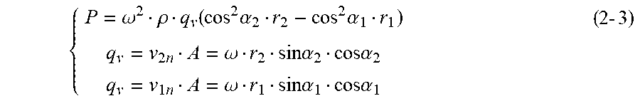
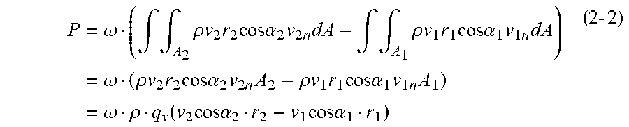
2. The method according to claim 1, wherein said shape design of said fan blade comprises equations as follows: P=.omega..intg..intg..rho.({right arrow over (r)}{right arrow over (.nu.)}).nu..sub.ndA (2-1) where P is a power of said fan wheel, .omega. being an angular velocity of said fan wheel, .rho. being an air density, {right arrow over (r)} being an outer diameter vector of said fan blade, {right arrow over (.nu.)} being an absolute velocity vector of said fan blade, .nu..sub.n being a relative velocity of said fan blade, A being an air outlet area; an equation (2-2) being derived from said equation (2-1) as follows: P = .omega. ( .intg. .intg. A 2 .rho. v 2 r 2 cos .alpha. 2 v 2 n dA - .intg. .intg. A 1 .rho. v 1 r 1 cos .alpha. 1 v 1 n dA ) = .omega. ( .rho. v 2 r 2 cos .alpha. 2 v 2 n A 2 - .rho. v 1 r 1 cos .alpha. 1 v 1 n A 1 ) = .omega. .rho. q v ( v 2 cos .alpha. 2 r 2 - v 1 cos .alpha. 1 r 1 ) ( 2 - 2 ) ##EQU00005## where .nu..sub.2 is an absolute velocity of an outer diameter of said fan blade, .nu..sub.1 being an absolute velocity of an internal diameter of said fan blade, r.sub.2 being said outer diameter of said fan blade, r.sub.1 being said internal diameter of said fan blade, .nu..sub.2n being a relative velocity of said outer diameter of said fan blade, .nu..sub.1n being a relative velocity of said internal diameter of said fan blade, A.sub.2 being an air outlet area of said outer diameter of said fan blade, A.sub.1 being an air outlet area of said internal diameter of said fan blade, .alpha..sub.2 being an air outlet angle of said fan blade, .alpha..sub.1 being an air intake angle of said fan blade, q.sub.v being an air volume generated by said fan blade; an equation (2-3) being derived from dividing said equation (2-2) as follows: { P = .omega. 2 .rho. q v ( cos 2 .alpha. 2 r 2 - cos 2 .alpha. 1 r 1 ) q v = v 2 n A = .omega. r 2 sin .alpha. 2 cos .alpha. 2 q v = v 1 n A = .omega. r 1 sin .alpha. 1 cos .alpha. 1 ( 2 - 3 ) ##EQU00006## equations (2-4) and (2-5) being derived from transforming said equation (2-2), sin .alpha..sub.2cos .alpha..sub.2(1-cos.sup.2 .alpha..sub.2) (2-4) sin .alpha..sub.1cos .alpha..sub.1(1+cos.sup.2 .alpha..sub.1) (2-5)
3. The method according to claim 1, wherein said air outlet angle .alpha..sub.2 is between 58.degree. and 64.degree., said air intake angle .alpha..sub.1 being between 37.degree. and 45.degree..
4. The method according to claim 1, wherein said air outlet angle .alpha..sub.2 is 60.degree., said air intake angle .alpha..sub.1 being 38.degree..
Description
BACKGROUND OF THIS INVENTION
1. Field of this Invention
[0001] This invention relates to an air cleaner and relates particularly to a method of producing a centrifugal fan wheel without a volute casing.
2. Description of the Related Art
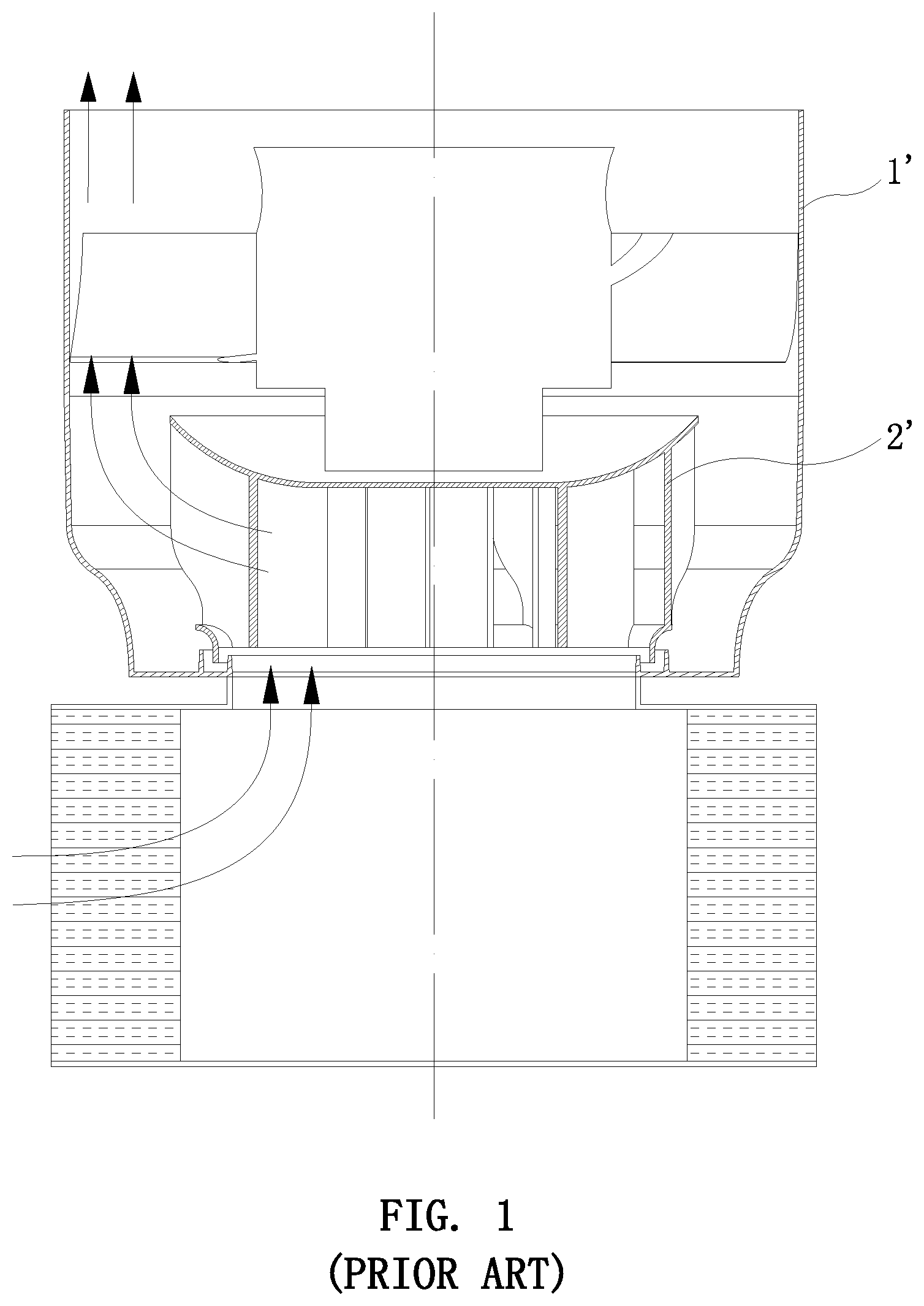
[0002] As shown in FIG. 1, an air duct system of a centrifugal fan wheel without a volute casing is generally applied to the power mechanism of most home air cleaners. The air duct system includes a casing 1' and a fan wheel 2'. The air duct system of the centrifugal fan wheel is capable of achieving equal air outlet, and providing a straight air intake direction and a straight air outlet direction, and this structure fits requirements of most home air cleaners. Most fan wheels are designed and developed by experience, and that lacks guidance of scientific theory. Nearly, outer diameters of all normal centrifugal fan wheels are designed by single grade outer diameter. Through the simulation analysis of aerodynamics, it can be found that the distribution of the air outlet cross section of jet streams of the fan wheel is not equal for the air duct system of the centrifugal fan wheel without the volute casing. Self-loss jet streams will be caused when air streams are near to an air intake opening, which results in the major source of noise.
SUMMARY OF THIS INVENTION
[0003] The object of this invention is to provide a method of producing a low-noise centrifugal fan wheel without a volute based on scientific theory.
[0004] In order to achieve the above object, the invention adopts the following technical solutions:
[0005] A method of producing a centrifugal fan wheel without a volute casing comprises a design of an outer diameter of a fan wheel and a shape design of a fan blade.
[0006] The design of the outer diameter of the fan wheel comprises the following steps of:
[0007] (1) calculating a first grade outer diameter of the fan wheel by an equation R.sub.fan1=.delta.*R.sub.ad where .delta. is a non-dimensional coefficient. .delta. is more than 0.72 and less than 0.75. R.sub.ad is an internal diameter of an air duct. R.sub.fan1 is the first grade outer diameter of the fan wheel; and
[0008] (2) calculating a second grade outer diameter of the fan wheel by an equation R.sub.fan2=.xi.*R.sub.fan1, where R.sub.fan1 is the first grade outer diameter. .xi. is a non-dimensional coefficient. .xi. is more than 0.89 and less than 0.92. R.sub.fan2 is the second grade outer diameter of the fan wheel.
[0009] The shape design of the fan blade comprises equations as follows:
P=.omega..intg..intg..rho.({right arrow over (r)}{right arrow over (.nu.)}).nu..sub.ndA (2-1)
[0010] where P is a power of the fan wheel. .omega. is an angular velocity of the fan wheel. .rho. is an air density. {right arrow over (r)} is an outer diameter vector of the fan blade. {right arrow over (.nu.)} is an absolute velocity vector of the fan blade. .nu..sub.n is a relative velocity of the fan blade. A is an air outlet area;
[0011] an equation (2-2) is derived from the equation (2-1) as follows:
P = .omega. ( .intg. .intg. A 2 .rho. v 2 r 2 cos .alpha. 2 v 2 n dA - .intg. .intg. A 1 .rho. v 1 r 1 cos .alpha. 1 v 1 n dA ) = .omega. ( .rho. v 2 r 2 cos .alpha. 2 v 2 n A 2 - .rho. v 1 r 1 cos .alpha. 1 v 1 n A 1 ) = .omega. .rho. q v ( v 2 cos .alpha. 2 r 2 - v 1 cos .alpha. 1 r 1 ) ( 2 - 2 ) ##EQU00001##
[0012] where .nu..sub.2 is an absolute velocity of an outer diameter of the fan blade. .nu..sub.1 is an absolute velocity of an internal diameter of the fan blade. r.sub.2 is the outer diameter of the fan blade. r.sub.1 is the internal diameter of the fan blade. .nu..sub.2n is a relative velocity of the outer diameter of the fan blade. .nu..sub.1n is a relative velocity of the internal diameter of the fan blade. A.sub.2 is an air outlet area of the outer diameter of the fan blade. A.sub.1 is an air outlet area of the internal diameter of the fan blade. .alpha..sub.2 is an air outlet angle of the fan blade. .alpha..sub.1 is an air intake angle of the fan blade. q.sub.v is an air volume generated by the fan blade;
[0013] an equation (2-3) is derived from dividing the equation (2-2) as follows:
{ P = .omega. 2 .rho. q v ( cos 2 .alpha. 2 r 2 - cos 2 .alpha. 1 r 1 ) q v = v 2 n A = .omega. r 2 sin .alpha. 2 cos .alpha. 2 q v = v 1 n A = .omega. r 1 sin .alpha. 1 cos .alpha. 1 ( 2 - 3 ) ##EQU00002##
[0014] equations (2-4) and (2-5) are derived from transforming the equation (2-2),
sin .alpha..sub.2cos .alpha..sub.2(1-cos.sup.2 .alpha..sub.2) (2-4)
sin .alpha..sub.1cos .alpha..sub.1(1+cos.sup.2 .alpha..sub.1) (2-5)
[0015] Preferably, the air outlet angle .alpha..sub.2 is between 58.degree. and 64.degree. and the air intake angle .alpha..sub.1 is between 37.degree. and 45.degree..
[0016] Preferably, the air outlet angle .alpha..sub.2 is 60.degree., and the air intake angle .alpha..sub.1 is 38.degree..
[0017] After adopting the above method, the invention comprises the design of the outer diameter of the fan wheel and the shape design of the fan blade. The invention combines aerodynamic simulation and theoretical calculation of rotating machine to propose the method of designing the centrifugal fan wheel without the volute casing. It determines the core calculation parameters, and removes the source of noise by eliminating self-loss jet streams to thereby achieve the object of increasing the aerodynamic performance.
[0018] The centrifugal fan wheel of the invention reduces the absolute velocity of the fan blade =.omega.R.sub.fancos .alpha..sub.2 by decreasing the outer diameter of the fan blade in a concentration area of the jet streams to thereby eliminate a self-loss area of the jet streams, and attain the object of reducing noise. The invention determines the self-loss area of the jet streams of an air duct system of the centrifugal fan wheel without the volute casing by the aerodynamic simulation, and provides the fan wheel which has the outer diameter designed by the second grade outer diameter. The invention introduces the second grade outer diameter of the coefficient .xi. to thereby eliminate the self-loss of the jet streams which is near to an air intake opening, and reduce noise without decreasing the air volume.
[0019] The invention is further described with drawings and detailed description as follows.
BRIEF DESCRIPTION OF THE DRAWINGS
[0020] FIG. 1 is a schematic view showing a structure of the air duct system of the centrifugal fan wheel without the volute casing;
[0021] FIG. 2 is an axonometric view of the fan wheel of this invention;
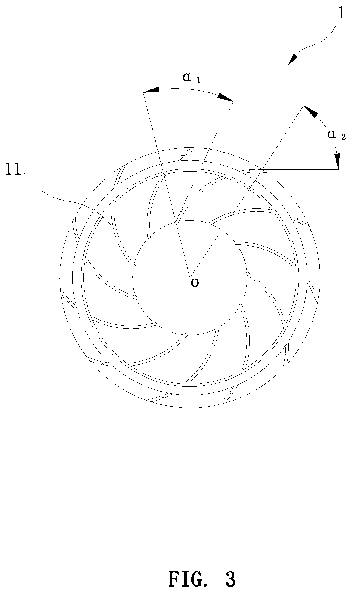
[0022] FIG. 3 is a top plan view of the fan wheel of this invention; and
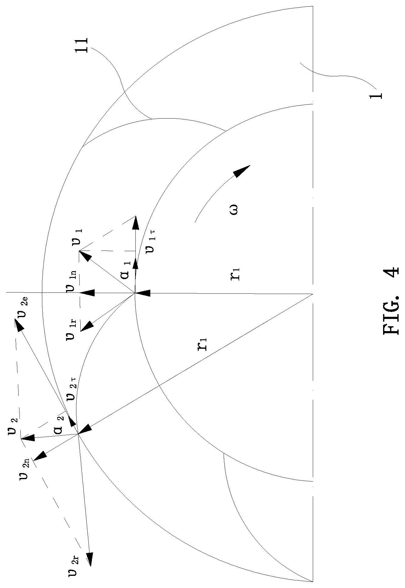
[0023] FIG. 4 is a schematic view showing parameters of the fan wheel of this invention.
DETAILED DESCRIPTION OF THE PREFERRED EMBODIMENTS
[0024] As shown in FIGS. 2 to 4, the invention is a method of producing a centrifugal fan wheel without a volute casing includes a design of an outer diameter of the fan wheel 1 and a shape design of a fan blade 11.
[0025] The design of the outer diameter of the fan wheel 1 comprises the following steps of:
[0026] (1) calculating a first grade outer diameter of the fan wheel 1 by an equation R.sub.fan1=.delta.*R.sub.ad where .delta. is a non-dimensional coefficient. .delta. is more than 0.72 and less than 0.75. R.sub.ad is an internal diameter of an air duct. R.sub.fan1 is the first grade outer diameter of the fan wheel; and
[0027] (2) calculating a second grade outer diameter of the fan wheel 1 by an equation R.sub.fan2=.xi.*R.sub.fan1, where R.sub.fan1 is the first grade outer diameter. .xi. is a non-dimensional coefficient. .xi. is more than 0.89 and less than 0.92. R.sub.fan2 is the second grade outer diameter of the fan wheel, as shown in FIG. 3.
[0028] The shape design of the fan blade 11 comprises equations as follows:
P=.omega..intg..intg..rho.({right arrow over (r)}{right arrow over (.nu.)}){right arrow over (.nu.)}.sub.ndA (2-1)
[0029] where P is a power of the fan wheel. .omega. is an angular velocity of the fan wheel. .rho. is an air density. {right arrow over (r)} is an outer diameter vector of the fan blade. {right arrow over (.nu.)} is an absolute velocity vector of the fan blade. .nu..sub.n is a relative velocity of the fan blade. A is an air outlet area;
[0030] an equation (2-2) is derived from the equation (2-1) as follows:
P = .omega. ( .intg. .intg. A 2 .rho. v 2 r 2 cos .alpha. 2 v 2 n dA - .intg. .intg. A 1 .rho. v 1 r 1 cos .alpha. 1 v 1 n dA ) = .omega. ( .rho. v 2 r 2 cos .alpha. 2 v 2 n A 2 - .rho. v 1 r 1 cos .alpha. 1 v 1 n A 1 ) = .omega. .rho. q v ( v 2 cos .alpha. 2 r 2 - v 1 cos .alpha. 1 r 1 ) ( 2 - 2 ) ##EQU00003##
[0031] where .nu..sub.2 is an absolute velocity of an outer diameter of the fan blade. .nu..sub.1 is an absolute velocity of an internal diameter of the fan blade. r.sub.2 is the outer diameter of the fan blade. r.sub.1 is the internal diameter of the fan blade. .nu..sub.2n is a relative velocity of the outer diameter of the fan blade. .nu..sub.1n is a relative velocity of the internal diameter of the fan blade. A.sub.2 is an air outlet area of the outer diameter of the fan blade. A.sub.1 is an air outlet area of the internal diameter of the fan blade. .alpha..sub.2 is an air outlet angle of the fan blade. .alpha..sub.1 is an air intake angle of the fan blade. q.sub.v is an air volume generated by the fan blade; as shown in FIG. 4.
[0032] an equation (2-3) is derived from dividing the equation (2-2) as follows:
{ P = .omega. 2 .rho. q v ( cos 2 .alpha. 2 r 2 - cos 2 .alpha. 1 r 1 ) q v = v 2 n A = .omega. r 2 sin .alpha. 2 cos .alpha. 2 q v = v 1 n A = .omega. r 1 sin .alpha. 1 cos .alpha. 1 ( 2 - 3 ) ##EQU00004##
[0033] In order to maximize the aerodynamic performance, the air outlet angle .alpha..sub.2 and the air intake angle .alpha..sub.1 must be adjusted so that the air volume q.sub.v generated by the fan wheel is the largest, the full pressure is the smallest, and the loss is the lowest when the power P is the smallest.
[0034] equations (2-4) and (2-5) are derived from transforming the equation (2-2) in order to optimize the air intake angle and the air outlet angle.
sin .alpha..sub.2cos .alpha..sub.2(1-cos.sup.2 .alpha..sub.2) (2-4)
sin .alpha..sub.1cos .alpha..sub.1(1+cos.sup.2 .alpha..sub.1) (2-5)
[0035] When the solutions of the equations (2-4) and (2-5) take the maximum value, the angles .alpha..sub.2 and .alpha..sub.1 which are obtained are the best values. The obtained air outlet angle .alpha..sub.2 is 60.degree., and the obtained air intake angle .alpha..sub.1 is 38.degree.. The invention specifies the protected range of the air outlet angle .alpha..sub.2 is between 58.degree. and 64.degree., and the protected range of the air intake angle .alpha..sub.1 is between 37.degree. and 45.degree..
[0036] The best air outlet angle .alpha..sub.2 is 60.degree.. The best air intake angle .alpha..sub.1 is 38.degree..
[0037] While the embodiment of the invention is shown and described above, it is understood that the embodiment is not intended to limit the technical scope of the invention. Moreover, it is understood that further detailed revisions, equivalent variations, and modifications may be made without departing from the scope of the invention.
* * * * *
D00000
D00001
D00002
D00003
D00004
P00001
XML
uspto.report is an independent third-party trademark research tool that is not affiliated, endorsed, or sponsored by the United States Patent and Trademark Office (USPTO) or any other governmental organization. The information provided by uspto.report is based on publicly available data at the time of writing and is intended for informational purposes only.
While we strive to provide accurate and up-to-date information, we do not guarantee the accuracy, completeness, reliability, or suitability of the information displayed on this site. The use of this site is at your own risk. Any reliance you place on such information is therefore strictly at your own risk.
All official trademark data, including owner information, should be verified by visiting the official USPTO website at www.uspto.gov. This site is not intended to replace professional legal advice and should not be used as a substitute for consulting with a legal professional who is knowledgeable about trademark law.