Heat Exchanger Comprising A Multi-channel Distribution Element
CRAYSSAC; Frederic ; et al.
U.S. patent application number 16/636165 was filed with the patent office on 2020-11-26 for heat exchanger comprising a multi-channel distribution element. The applicant listed for this patent is L'Air Liquide, Societe Anonyme pour l'Etude et I'Exploitation des Precedes Georges Claude. Invention is credited to Sebastien CADALEN, Frederic CRAYSSAC, Quentin SANIEZ, Marc WAGNER.
| Application Number | 20200370836 16/636165 |
| Document ID | / |
| Family ID | 1000005022107 |
| Filed Date | 2020-11-26 |


| United States Patent Application | 20200370836 |
| Kind Code | A1 |
| CRAYSSAC; Frederic ; et al. | November 26, 2020 |
HEAT EXCHANGER COMPRISING A MULTI-CHANNEL DISTRIBUTION ELEMENT
Abstract
A heat exchanger of the brazed plate and fin type, including a plurality of plates arranged in a mutually parallel manner so as to define at least one set of passages for a first fluid configured to exchange heat with at least a second fluid to flow through, the passages extending in a longitudinal direction and a lateral direction perpendicular to said longitudinal direction, each passage being divided, in the longitudinal direction, into at least one distribution zone and one heat-exchange zone, the at least one distribution zone of a passage comprising a distribution element, said distribution element including a plurality of dividing walls arranged so as to divide said distribution zone into a plurality of channels for the first fluid to flow through.
| Inventors: | CRAYSSAC; Frederic; (Velizy, FR) ; CADALEN; Sebastien; (Paris, FR) ; WAGNER; Marc; (Saint Maur des Fosses, FR) ; SANIEZ; Quentin; (Paris, FR) | ||||||||||
| Applicant: |
|
||||||||||
|---|---|---|---|---|---|---|---|---|---|---|---|
| Family ID: | 1000005022107 | ||||||||||
| Appl. No.: | 16/636165 | ||||||||||
| Filed: | July 16, 2018 | ||||||||||
| PCT Filed: | July 16, 2018 | ||||||||||
| PCT NO: | PCT/FR2018/051804 | ||||||||||
| 371 Date: | February 3, 2020 |
| Current U.S. Class: | 1/1 |
| Current CPC Class: | F28F 3/025 20130101; F25J 5/002 20130101; F28F 9/0268 20130101; F28D 9/0062 20130101; F25J 2290/32 20130101; F28D 2021/0033 20130101 |
| International Class: | F28D 9/00 20060101 F28D009/00; F25J 5/00 20060101 F25J005/00 |
Foreign Application Data
| Date | Code | Application Number |
|---|---|---|
| Aug 4, 2017 | FR | 1757539 |
Claims
1.-17. (canceled)
18. A heat exchanger of the brazed plate and fin type, comprising: a plurality of plates arranged in a mutually parallel manner so as to define at least one set of passages for a first fluid configured to exchange heat with at least a second fluid to flow through, the passages extending in a longitudinal direction and a lateral direction perpendicular to said longitudinal direction, each passage being divided, in the longitudinal direction, into at least one distribution zone and one heat-exchange zone, the at least one distribution zone of a passage comprising a distribution element, said distribution element comprising a plurality of dividing walls arranged so as to divide said distribution zone into a plurality of channels for the first fluid to flow through, said channels defining flow paths of different lengths and having variable passage sections for fluid along said flow paths, wherein in that the dividing walls of the distribution element are secured together via a support, said support being brazed to an adjacent plate.
19. The heat exchanger as claimed in claim 18, wherein the dividing wall project from the support into the passage.
20. The heat exchanger as claimed in claim 19, wherein the support comprises a flat bottom, the dividing walls projecting perpendicularly to the bottom.
21. The heat exchanger as claimed in claim 18, further comprising a first end forming an inlet or an outlet for the first fluid and a second end fluidically connected to the heat-exchange zone when the distribution element is arranged in a distribution zone, each dividing wall being formed from a single part and extending continuously from the first end to the second end.
22. The heat exchanger as claimed in claim 21, wherein each channel is provided with a first opening and a second opening situated at the first and second ends, respectively, at least one first opening having a passage section for fluid that is different than the passage section for fluid of another first opening, and/or at least one second opening having a passage section for fluid that is different than the passage section for fluid of another second opening.
23. The heat exchanger as claimed in claim 22, wherein the first openings and/or the second openings of one and the same channel have passage sections for fluid that are larger the longer the flow path defined by said channel.
24. The heat exchanger as claimed in claim 18, wherein one or more channels comprise means for modifying the linear flow resistance of said channels.
25. The heat exchanger as claimed in claim 24, wherein said means comprise a shape of the interior profiles of said channels.
26. The heat exchanger as claimed in claim 24, wherein said means comprise partitions arranged within said channels.
27. The heat exchanger as claimed in claim 24, wherein said means comprise porous structures arranged within said channels.
28. The heat exchanger as claimed in claim 18, wherein the dividing walls have rectilinear profiles in longitudinal section.
29. The heat exchanger as claimed in claim 18, wherein the dividing walls have predetermined curvilinear profiles in longitudinal section.
30. The heat exchanger as claimed in claim 29, wherein said predetermined curvilinear profiles comprise at least one inflection point.
31. The heat exchanger as claimed in claim 18, wherein the distribution element extends along a length in a longitudinal direction and across a width in a lateral direction, the ratio between a length and the width being less than 20%.
32. The heat exchanger as claimed in claim 18, wherein the distribution element extends along a length less than 500 mm.
33. The heat exchanger as claimed in claim 18, wherein the distribution element has a height, measured in a vertical direction orthogonal to the plates, of at least 2 mm.
34. The heat exchanger as claimed in claim 18, wherein the distribution element is a monolithic element manufactured by an additive manufacturing method or by casting.
Description
CROSS REFERENCE TO RELATED APPLICATIONS
[0001] This application is a 371 of International PCT Application No. PCT/FR2018/051804, filed Jul. 16, 2018, which claims priority to French Patent Application No. 1757539, filed Aug. 4, 2017, the entire contents of which are incorporated herein by reference.
BACKGROUND
[0002] The present invention relates to a distribution element configured to be arranged in a distribution zone of a heat exchanger of the plate and fin type, and to a heat exchanger comprising such a distribution element and at least one set of passages for a fluid to be put into a heat-exchange relationship with at least one other fluid. The element according to the invention allows more homogeneous distribution of the fluid across the width of said passages.
[0003] The present invention finds application notably in the field of the cryogenic separation of gases, in particular the cryogenic separation of air, in what is known as an ASU (air separation unit) used to produce pressurized gaseous oxygen. In particular, the present invention may be applied to a heat exchanger that vaporizes a flow of liquid, for example oxygen, nitrogen and/or argon by exchange of heat with a gas.
[0004] The present invention may also be applied to a heat exchanger that vaporizes at least one flow of liquid-gas mixture, in particular a flow of multi-constituent mixture, for example a mixture of hydrocarbons, through exchange of heat with at least one other fluid, for example natural gas.
[0005] The technology commonly used for a heat exchanger is that of aluminum brazed plate and fin heat exchangers, which make it possible to obtain devices that are very compact and afford a large heat-exchange surface area.
[0006] These heat exchangers comprise plates, between which are inserted heat-exchange corrugations, formed of a succession of fins or corrugation legs, thereby constituting a stack of passages for the various fluids to be put into a heat-exchange relationship.
[0007] These passages comprise zones referred to as distribution zones, which are arranged, in the overall direction of flow of the fluid in the passage in question, upstream and downstream of the actual heat-exchange zone. The distribution zones are fluidly connected to semi-tubular headers configured to distribute the various fluids selectively to the various passages, and to remove said fluids from said passages.
[0008] In a known way, these distributors generally comprise distribution corrugations, arranged in the form of corrugated sheets between two successive plates. The distribution corrugations are generally perforated straight corrugations cut into the shape of triangles or trapeziums. They divert the fluid coming from the inlet header of the heat exchanger in order to spread it across the width of the heat-exchange zones, and recover the fluid coming from said heat-exchange zone. The distribution corrugations also act as spacers in order to ensure the mechanical integrity upon brazing and during operation of the distribution zone of the passage. Such distribution corrugations are known from the documents U.S. Pat. No. 6,044,902 and EP-A-0507649. Also known, from the document EP-A-3150952, is a plate heat exchanger in which the distribution elements are formed by the actual plates, which are pressed.
[0009] One of the problems that arise with the configuration of the current distribution zones is the poor distribution of fluids toward toward the heat-exchange zones. Specifically, the distribution zones are occupied by at least two pads of corrugations in order to optimize the offcuts from the shaping process, thus increasing the risk of clearance between the pads. The assembly of the corrugation pads can also cause incidents along the flow path of the fluid, and this contributes to increasing the pressure drops in the distribution zones. Because of these imperfections in the distribution zones, variations in flow rate with an amplitude of around 10% may arise, these being detrimental to the correct operation of the heat exchanger.
[0010] Similarly, distribution defects are found in the distribution zones dedicated to the recovery of the fluids coming from the heat-exchange zones.
[0011] Another problem relates to the mechanical integrity of the distribution zones. Specifically, these zones are provided with corrugations with lower densities, typically between 6 and 10 legs per inch, than those of the heat-exchange zones. Currently, the distribution zone of a passage extends typically along a length, measured in a longitudinal direction corresponding to the direction of flow of the fluid in the heat-exchange zone of the same passage, of around 200 to 600 mm, and across a width, measured perpendicularly to said longitudinal direction, of around 500 to 1500 mm. Since the distribution zones constitute parts with lower mechanical integrity than the heat-exchange zones, it is desirable to limit the longitudinal extent thereof as much as possible in order to ensure better resistance of the heat exchanger during the circulation of fluids at high pressure within the passages.
SUMMARY
[0012] It is an object of the present invention to fully or partially solve the abovementioned problems, notably by proposing a heat exchanger in which the distribution of the fluid(s) in the heat-exchange zones is as uniform as possible, and which also has distribution zones that take up less space than in the prior art.
[0013] The solution according to the invention is therefore a heat exchanger of the brazed plate and fin type, comprising: [0014] a plurality of plates arranged in a mutually parallel manner so as to define at least one set of passages for a fluid intended to exchange heat with at least one other fluid to flow through, the passages extending in a longitudinal direction and a lateral direction perpendicular to said longitudinal direction, [0015] each passage being divided, in the longitudinal direction, into at least one distribution zone and one heat-exchange zone, [0016] at least one distribution zone of a passage comprising a distribution element, said distribution element comprising a plurality of dividing walls arranged so as to divide said distribution zone into a plurality of channels for the fluid to flow through, said channels defining flow paths of different lengths and having variable passage sections for fluid along said flow paths.
[0017] As the case may be, the element of the invention may comprise one or more of the following technical features: [0018] the dividing walls of the distribution element are secured together via a support, [0019] the support is brazed to an adjacent plate. [0020] the dividing walls project from the support into the passage. [0021] the support comprises a flat bottom, the dividing walls projecting perpendicularly to the bottom. [0022] the element comprises a first end forming an inlet or an outlet for the fluid and a second end fluidically connected to the heat-exchange zone when the distribution element is arranged in a distribution zone, each dividing wall being formed from a single part and extending continuously from the first end to the second end. [0023] each channel is provided with a first opening and a second opening situated at the first and second ends, respectively. [0024] at least one first opening has a passage section for fluid that is different than the passage section for fluid of another first opening, and/or at least one second opening has a passage section for fluid that is different than the passage section for fluid of another second opening. [0025] the first openings and/or the second openings of one and the same channel have passage sections for fluid that are larger the longer the flow path defined by said channel. [0026] one or more channels comprise means for modifying the linear flow resistance of said channels. [0027] said means comprise a shape of the interior profiles of said channels. [0028] said means comprise partitions arranged within said channels. [0029] said means comprise porous structures, for example metal foams, arranged within said channels. [0030] the dividing walls have rectilinear profiles in longitudinal section. [0031] the dividing walls have predetermined curvilinear profiles in longitudinal section. [0032] said predetermined curvilinear profiles comprise at least one inflection point. [0033] the distribution element extends along a length in a longitudinal direction and across a width in a lateral direction, the ratio between a length and the width being less than 20%, preferably between 5 and 10%. [0034] the distribution element extends along a length less than 500 mm, preferably between 50 and 200 mm. [0035] the distribution element has a height, measured in a vertical direction orthogonal to the plates, of at least 2 mm, preferably at least 5 mm, preferably a height of between 2 and 15 mm. [0036] the distribution element is a monolithic element, preferably manufactured by an additive manufacturing method or by casting.
BRIEF DESCRIPTION OF THE DRAWINGS
[0037] The present invention will now be understood better by virtue of the following description, which is given solely by way of nonlimiting example and with reference to the appended drawings, in which:
[0038] FIG. 1 is a three-dimensional schematic view of a heat exchanger of the plate and fin type;
[0039] FIG. 2 is a partial schematic view in longitudinal section of a distribution zone according to one embodiment of the invention;
[0040] FIG. 3A is a partial schematic view in longitudinal section of distribution zones according to other embodiments of the invention;
[0041] FIG. 3B is a partial schematic view in longitudinal section of distribution zones according to other embodiments of the invention;
[0042] FIG. 4 is a partial schematic view in longitudinal section of distribution zones according to other embodiments of the invention;
[0043] FIG. 5A is a schematic view in longitudinal section of a distribution zone according to another embodiment of the invention;
[0044] FIG. 5B is a three-dimensional schematic view of a distribution zone according to another embodiment of the invention;
[0045] FIG. 6A presents a result of a simulation carried out with a distribution element as depicted schematically in FIG. 5B;
[0046] FIG. 6B presents a result of a simulation carried out with a distribution element as depicted schematically in FIG. 58;
[0047] FIG. 6C presents a result of a simulation carried out with a distribution element as depicted schematically in FIG. 5B;
[0048] FIG. 7 presents a result of a simulation carried out with a distribution element as depicted schematically in FIG. 5.
DETAILED DESCRIPTION OF PREFERRED EMBODIMENTS
[0049] As can be seen in FIG. 1, a heat exchanger 1 of the plate and fin type comprises a stack of plates 2 that extend in two dimensions, length and width, in the longitudinal direction z and the lateral direction y, respectively. The plates 2 are disposed parallel to and above one another with a spacing, and thus form several sets of passages 3, 4, 5 for fluids F1, F2, F3 to be put into an indirect heat-exchange relationship via the plates 2. The lateral direction y is orthogonal to the longitudinal direction z and parallel to the plates 2. Preferably, the longitudinal axis is vertical when the heat exchanger 1 is in operation.
[0050] Preferably, each passage has a flat and parallelepipedal shape. The passages extend lengthwise in the longitudinal direction z and widthwise in the lateral direction y. The separation between two successive plates is small in comparison with the length and the width of each successive plate.
[0051] Each passage 3, 4, 5 is divided, in the longitudinal direction z, into at least one distribution zone 20 and one heat-exchange zone 21. The flow of the fluids within the distribution zones takes place overall parallel to the longitudinal direction z. The distribution zone 20 and heat-exchange zone 21 are preferably juxtaposed along the longitudinal axis z.
[0052] According to the depiction in FIG. 1, considering in particular the passage 3, the internal part of which has been made visible, two distribution zones 20 are arranged on either side of the heat-exchange zone 21, one serving to carry the fluid F1 toward the heat-exchange zone 21 and the other serving to evacuate it from said zone. Conventional distribution corrugations made in the form of corrugated products are shown in the distribution zones 20.
[0053] In a manner known per se, the heat exchanger 1 comprises semi-tubular headers 7, 9 provided with openings 10 for introducing the fluids into the heat exchanger 1 and evacuating the fluids from the heat exchange 1. These headers have openings that are less wide than the passages. The distribution zones 20 serve to distribute the fluids introduced through the openings in the headers across the entire width of the passages.
[0054] According to the invention, a distribution element is arranged in at least one distribution zone 20 of a passage 3 of the heat exchanger, this element comprising a plurality of dividing walls 25 that are arranged so as to divide said distribution zone 20 into a plurality of channels 26 for the fluid F1 to flow through. Said channels 26 define flow paths with different lengths and have variable passage sections for fluid along said flow paths. Subdividing the distribution zone into a plurality of separate channels with variable lengths and sections makes it possible to divert the fluid while finely controlling the flow conditions for the fluid within each channel. In particular, it is possible to balance out the velocities of the fluid flowing through the different channels, so as to obtain more or less identical fluid velocities at the outlet of each channel, and hence a uniform or quasi-uniform distribution of the fluid across the width of the passages at the outlet of the distribution zone, while minimizing pressure drops in the distribution zone.
[0055] Moreover, the distribution element confers structural rigidity on the distribution zone of the heat exchanger since the spacer function can be ensured by the dividing walls.
[0056] It should be noted that, within the scope of the invention, the heat exchanger is of the brazed plate and fin type, meaning that the separate elements that make up the heat exchangers are secured, directly or indirectly, by brazing. The distribution element according to the invention is separate from the plates 2.
[0057] "Brazed support" is understood as meaning that the support is connected or secured by brazing to an adjacent plate of the heat exchanger via at least a portion of the respective surfaces thereof.
[0058] It should be noted that the expression "passage section for fluid" means the area through which the fluid flows within the channel, this being measured in a plane perpendicular to the direction of movement of the fluid F1 in said channel, i.e. perpendicular to the stream lines of the moving fluid F1.
[0059] The length of the flow paths is understood to be the distance to be covered by the fluid F1 between the inlet and the outlet of the channel in question.
[0060] According to the invention, the distribution element also comprises a support 27 configured to keep the walls 25 secured together. An example of such an element is presented in FIG. 5B.
[0061] It will thus be understood that the distribution element is not a corrugated product, in contrast to the distribution corrugations conventionally disposed in the distribution zones of a brazed plate and fin heat exchanger. The walls 25 are secured together via one and the same support 27, thereby conferring greater rigidity on the distribution element. This also makes it possible to simplify the brazing operations. Moreover, such a configuration affords greater design freedom for the distribution element and geometric freedom for the channels thereof.
[0062] Thus, it is possible to dispose walls 25 with a relatively great height, typically at least 2 mm, preferably at least 5 mm, more preferably up to 15 mm, or more, in the passages, this not being the case with heat exchangers in which the walls result from pressing of the dividing plates.
[0063] Preferably, said support comprises a bottom 27, preferably a flat bottom that can be formed from a flat sheet, from which the dividing walls 25 are erected. The walls 25 are preferably erected in the vertical direction x. The walls 25 can have heights h of typically between 2 and 15 mm. Preferably, the heights are chosen such that the walls 25 extend over virtually all, if not all, of the height of the passage in the vertical direction x.
[0064] The configuration of the distribution element 22 according to the invention, in which the distribution element is a separate part from the plates, also makes it possible to design different distribution profiles on either side of one and the same plate.
[0065] Preferably, a distribution element according to the invention is housed in several, if not all, of the distribution zones of one or more sets of passages of the heat exchanger. Said element extends over virtually all, if not all, of the height of the passages, measured in the vertical direction x, such that the structure is advantageously in contact with each plate 2 forming the passage 20.
[0066] The channels are preferably fluidically isolated from one another. The flow parameters of each channel are thus controlled independently of those of the adjacent channels, thereby making it possible to precisely adjust the distribution of the fluid across the width of the passages at the outlet of the distribution zone. Advantageously, the separating walls 25 are erected perpendicularly to the plates 2.
[0067] Preferably, the number of channels 26 is at least 6, more preferably between 5 and 50. Specifically, the number of channels 26 on the one hand has to be high enough to give the element 22 its mechanical rigidity but on the other hand should not be too high in order to leave enough free volume for the fluid to flow and to limit pressure drops.
[0068] Advantageously, the distribution element 22 comprises a first end 23 forming an inlet or an outlet for the fluid F1, and a second end 24 fluidically connected to the heat-exchange zone 21.
[0069] More specifically, as can be seen in FIG. 1, the passages 3 to 5 are bordered by closure bars 6, which do not completely shut off the passages but leave free openings 23, 24 for the inlet or outlet of the corresponding fluids.
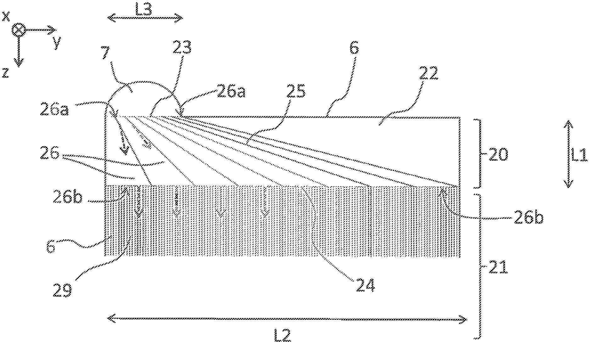
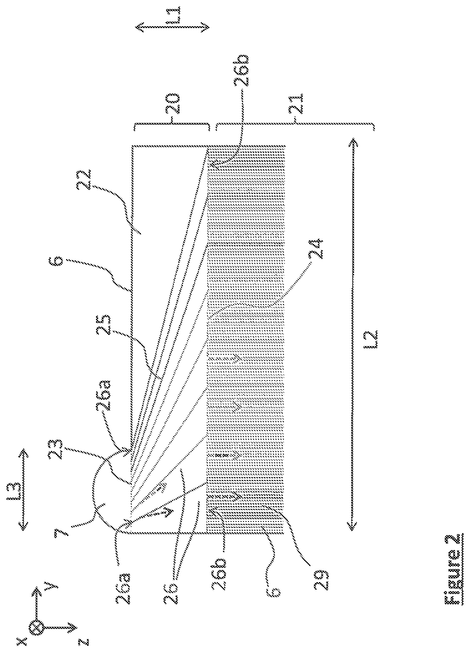
[0070] FIG. 2 schematically partially depicts the "inlet" part of a passage 3 of a heat exchanger according to one embodiment of the invention. A fluid header 7 is arranged in the left-hand corner of the heat exchanger, the first end 23 being fluidically connected to the header 7 and forming an inlet for the fluid F1, the flow of which is schematically depicted by dashed arrows.
[0071] The first and second ends 23, 24 extend preferably in a plane parallel to the lateral direction y and perpendicular to the longitudinal direction z. The dividing walls 25 extend between the first and second ends 23, 24 and form channels 26 that lead out at the second end 24 and are configured to distribute the fluid F1 uniformly in the lateral direction y so as to obtain homogeneous or quasi-homogeneous distribution towards or from the entire width of the heat-exchange zone 21 when the other of said first and second ends 23, 24 is fed with fluid F1.
[0072] Advantageously, each channel is provided with first openings 26a and second openings 26b. Advantageously, as schematically depicted in FIG. 2, the first and second openings 26a, 26b are situated at the first and second ends 23, 24, respectively, the dividing walls 25 extending continuously from the first end 23 to the second end 24. The flow path of the fluid F1 corresponds to the path to be followed between the openings 26a and 26b. Each of the ends 23, 24 can thus be divided into a series of openings 26a and a series of openings 26b, respectively.
[0073] The openings 26a, 26b of the channels 26 could have passage sections for fluid that are identical or variable depending on the channels 26 in question. The passage sections for fluid of the openings 26a and 26b correspond to the internal areas of the channels 26 measured at the first and second ends 23, 24 in a plane parallel to the lateral direction y.
[0074] Preferably, at least one first opening 26a has a passage section for fluid that is different than the passage section for fluid of another first opening 26a, and/or at least one second opening 26b has a passage section for fluid that is different than the passage section for fluid of another second opening 26b.
[0075] Advantageously, the first openings 26a and/or the second openings 26b of one and the same channel 26 have passage sections for fluid that are larger the longer the flow path defined by said channel 26, i.e. the greater the distance to be covered by the fluid F1 between the first opening 26a and the second opening 26b.
[0076] Thus, in the example in FIG. 3A, 3B or 5B, where the first end 23 is arranged at an extreme edge of the element 22 along the direction y, the first end 23 is subdivided into a first series of first openings 26a that have passage sections for fluid that increase in the lateral direction y. This encourages the supply of the channels that are configured to distribute the fluid F1 from the header 7 toward the part of the second end 23 that is diagonally opposite said extreme edge.
[0077] According to another example (FIG. 5A), in which the element 22 has a median plane M and the first end 23 is centered with respect to the plane M, the first openings 26a, which are arranged, preferably symmetrically, on either side of the plane M, have passage sections for fluid that increase with increasing distance from said median plane M.
[0078] This compensates for the natural tendency of the fluid to pass into the region of the distribution zone that is situated next to the header rather than through the zones that are further away from the header, and thus to homogenize the distribution of the fluid across the width of the passage 3 of the heat exchanger.
[0079] Advantageously, when the distribution element 22 is disposed in the distribution zone 20 of a heat exchanger, the first end 23 is situated by the inlet header 7 of the heat exchanger and forms an inlet for the fluid F1. The first openings 26a in the first end 23 have passage sections for fluid that are variable depending on their position along the lateral direction y.
[0080] By virtue of the use of openings 26a with different passage sections, it is notably possible to overfeed the channels that are less favorable to the passage of the fluid, specifically from the inlet of the fluid F1 into the distribution zone 20, this causing fewer pressure drops and thus leading to a more efficient fluid distribution system.
[0081] According to an advantageous embodiment of the invention, all or some of the channels 26 comprise means 28 for modifying the linear flow resistance of said channels 26. The linear flow resistance of each channel can thus be adjusted depending on the flow characteristics desired in each channel 26, in particular fluid flow rate and velocity. Thus, the linear flow resistance of the channels can be adjusted such that each channel 26 has a similar overall flow resistance. The characteristics of the fluid at the outlet of the channels 26 are thus homogenized in the lateral direction y, thereby allowing uniform distribution toward or from the heat-exchange zone 21.
[0082] The expression "flow resistance" is understood to mean the capability of the channel not only to generate viscous friction but also to divert the flow (pressure force normal to the wall). This resistance is expressed in the form of a reaction force of the solid structure to the flow in newtons, this resulting in the fluid in a pressure drop in pascals. This force depends firstly on the kinetic energy of the fluid (rho*u.sup.2) and secondly on the Reynolds number (rho*u*D/mu). The linear flow resistance corresponds to the flow resistance of the channel expressed per unit of length.
[0083] Advantageously, a channel 26 will comprise modification means 28 that are configured to produce an increase in the linear flow resistance that is all the greater the closer the opening 26a of said channel is, in terms of distance to be covered by the fluid F1, to the other opening 26b. For example, in the configuration illustrated in FIG. 3B, the channels 26 comprise modification means 28 that are configured to produce an increase in linear flow resistance that is increasingly small in the lateral direction y. Specifically, this makes it possible to compensate for the natural preferred passage of the fluid along the axis rather than along the side of the heat exchanger, and thus to obtain good distribution of the fluid. In the case in which the header 7 is centered with respect to the median plane M of the heat exchanger, as shown in FIG. 5A, the fluid resistance of a channel will be all the greater the closer it is to the median plane M.
[0084] The channels 26 could have internal profiles that are shaped to produce different variations in flow resistance.
[0085] Obstacles 28 that produce different flow resistances could also be arranged within one or more channels 26. The insertion of a porous structure 28, for example a metal foam, into a channel will make it possible to increase the flow resistance thereof. The linear flow resistance of the channels 26 could thus be adjusted by varying the characteristics of the inserted structures 28, such as volume, density, etc. in accordance with the channels. In the example illustrated in FIG. 3B, the volume taken up by the porous structures 28 decreases in the lateral direction y, so as to produce variations in linear flow resistance that are smaller along y.
[0086] According to the example schematically indicated in FIG. 4, partitions 28 can be arranged in one or more channels 26 so as to create an additional stage for dividing the distribution zone 22. This makes it possible to vary the linear flow resistance and to control the flow parameters of the fluid distributed toward or recovered from the heat-exchange zone 21 even more finely. The use of additional partitions 28 is notably advantageous when the first end 23 of the distribution element has a width that is too small to be able to be divided into a sufficient number of channels 26.
[0087] As the case may be, the dividing walls 25 and/or the partitions 28 may have, in longitudinal section, rectilinear profiles, as illustrated in FIGS. 2 and 4, or curvilinear profiles, as illustrated in FIGS. 3A, 3B and 5A, 5B.
[0088] According to a particularly advantageous embodiment, the dividing walls 25 have predetermined curvilinear profiles comprising at least one inflection point P.
[0089] Such a geometry makes it possible to divert the fluid more quickly, that is to say over a shorter distance L1, specifically across a great width of the passage of the heat exchanger. It is thus possible to reduce the longitudinal extent of the distribution zone 20 and consequently to increase the mechanical integrity of the heat exchanger since the compactness of what is known as the "weak" zone of the heat exchanger is increased.
[0090] This also affords the possibility of reducing the width of the first end 23 of the distribution element 22 and thus the width of the header 7, which is a relatively expensive part. Preferably, the first end 23 forming the inlet or outlet of the distribution element 22 has, in the lateral direction y, a width L3 of between 50 and 1000 mm, more preferably between 100 and 500 mm.
[0091] Such profiles also make it possible to reduce the pressure drops within the channels 26, sudden changes in channel profiles being known to bring about fluid recirculations that cause pressure drops.
[0092] Preferably, the distribution element 22 has, parallel to the longitudinal direction z, a length L1 less than 500 mm, preferably between 50 and 200 mm, more preferably between 80 and 100 mm. Preferably, the length L1 of the distribution element 22 represents less than 20% of the length of the heat-exchange zone 21. Parallel to the lateral direction y, the distribution element 22 has a width L2, the ratio between a length L1 and the width L2 being less than 20%, preferably between 5 and 10%. The width L2 is preferably between 500 and 1500 mm.
[0093] The distribution element 22 is advantageously formed from a metal material, preferably aluminum or an aluminum alloy. The element may be formed in particular from a porous material, preferably with closed pores, for example a metal foam.
[0094] Preferably, the distribution element 22 is monolithic, thereby making it possible to minimize incidents along the flow paths of the fluid.
[0095] The element 22 may be manufactured using an additive manufacturing method, preferably by thermal spraying, making it possible to produce parts with complex geometries in one piece. In particular, a cold spray method could be used.
[0096] It should be noted that the additive manufacturing method can also be referred to as "3D printing". Additive manufacturing makes it possible to produce a real object using a specific printer, which deposits and/or solidifies material, layer by layer, to obtain the final part. The stack of these layers makes it possible to create a volume.
[0097] The element 22 may also be manufactured using the following additive manufacturing methods: [0098] the FDM (Fused Deposition Modeling) method, which consists in modeling by deposition of molten material, [0099] stereolithography (SLA), a method in which ultraviolet radiation solidifies a layer of liquid plastic, or [0100] selective laser sintering, in which a laser is used to agglomerate a layer of powder.
[0101] Alternatively, the distribution element 22 may be manufactured by casting. This manufacturing method makes it possible to produce parts with complex geometries at a relatively low cost compared with additive manufacturing. Preferably, the element 22 is formed from an aluminum alloy by casting, that is to say an alloy of which the main constituent is aluminum, with a density lower than intended to be converted by casting techniques.
[0102] As regards the heat-exchange zones 21 of the heat exchanger, these advantageously comprise heat-exchange structures 8 disposed between the plates 2, as shown in FIG. 1. These structures have the function of increasing the heat-exchange area of the heat exchanger and act as spacers between the plates 2, notably during the assembly of the exchanger by brazing, in order to avoid any deformation of the plates during the use of pressurized fluids.
[0103] Preferably, these structures comprise heat-exchange corrugations 8 which advantageously extend across the width and along the length of the passages of the heat exchanger, parallel to the plates 2. These corrugations 8 may be formed in the form of corrugated sheets. In this case, the corrugation legs that connect the successive tops and bottoms of the corrugation are referred to as "fins". The heat-exchange structures 8 can also cover other particular shapes defined depending on the desired fluid flow characteristics. More generally, the term "fins" covers blades or other secondary heat-exchange surfaces, which extend from the primary heat-exchange surfaces, that is to say the plates of the heat exchanger, into the passages of the heat exchanger.
[0104] Within a passage, the distribution element 22 according to the invention and the heat-exchange structure 8 are preferably juxtaposed along the longitudinal axis z, that is to say positioned end to end. Note that a small clearance can exist between these elements in order not to block the channels of the heat-exchange zone 21 which face the walls 25 of the channels of the distribution zone 22. Preferably, the first end 23 of the element 22 is arranged end to end with at least one part of the header 7, while the second end 24 is arranged end to end with at least one part of the structure 8. Preferably, the structure 8, the header 7 and/or the element 22 are connected by brazing to the plate 2 and are connected indirectly together via their respective connections to the plates 2. Advantageously, the element 22 is assembled on the plates 2 by brazing the support 27 to the plates 2, the support or bottom 27 comprising at least one face coated with a brazing agent. This face is positioned next to a plate 2 so as to form a connecting surface with said plate 2. Alternatively or in addition, the plate 2 entirely or partially have at least one face coated at least partially with a brazing agent layer.
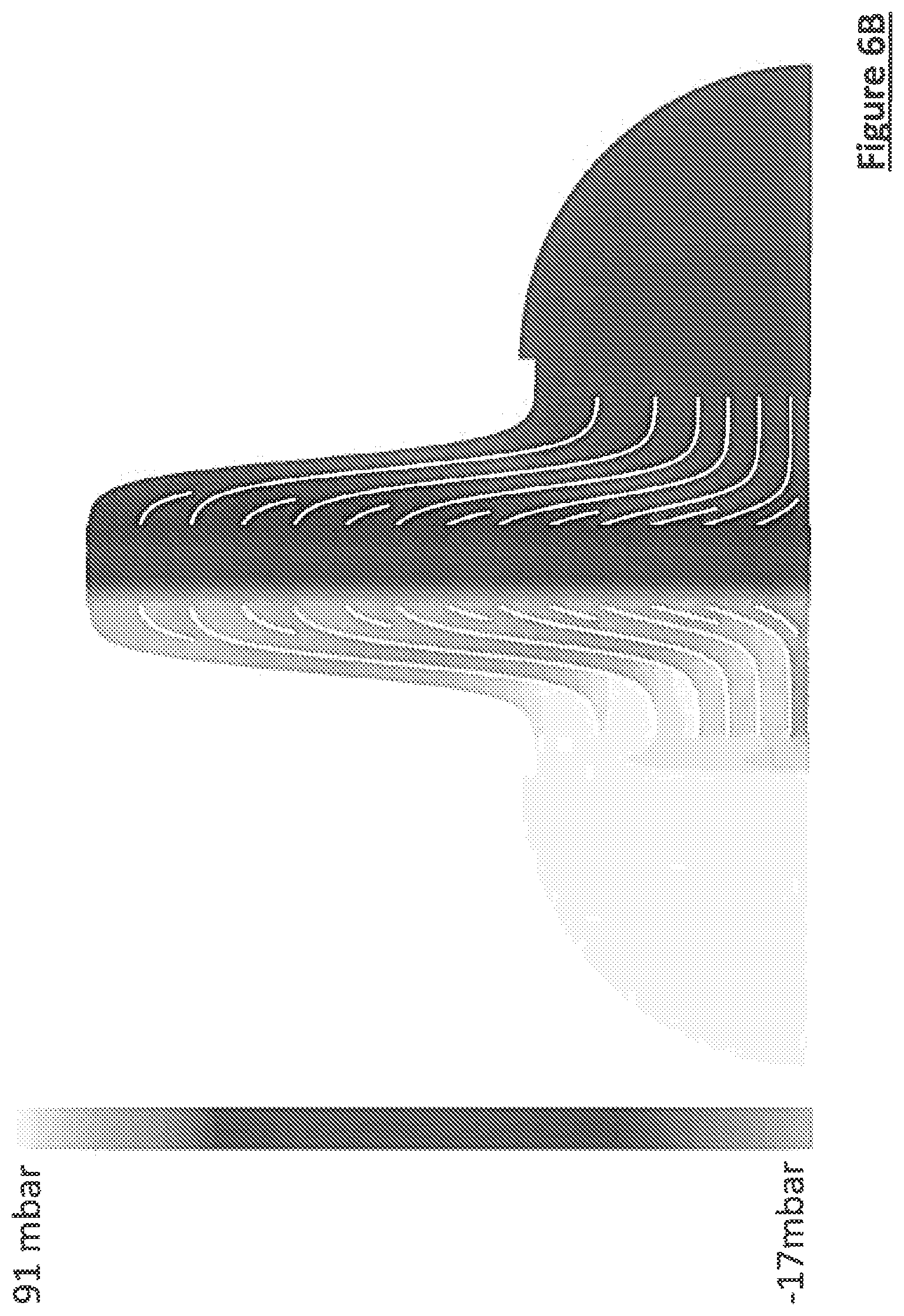
[0105] In order to demonstrate the effectiveness of a distribution element 22 according to the invention for uniformly distributing the fluid, fluid flow simulations were carried out with a distribution element according to FIG. 5B.
[0106] The dimensional characteristics of the distribution element 22 were as follows: [0107] length L1 of the element 22: 85 mm, [0108] half-width L2/2 of the element 22: 485 mm, [0109] width L3 of the first end 23 forming an inlet: 370 mm [0110] mechanical clearance between the distribution element 22 and the heat-exchange structure 8: 2 mm, [0111] height of the element 22: 9.5 mm (the walls 25 having a height, in the vertical direction x, of 7.5 mm, and the bottom 27 having a thickness of 2 mm), [0112] thickness of the walls 25: 2.3 mm.
[0113] As regards the fluid, the simulation parameters were as follows: [0114] nature of the fluid: nitrogen, [0115] pressure of the fluid at the outlet of the distribution element 22: 1.2 bar, [0116] temperature of the fluid at the inlet of the header 7: -80.degree. C., [0117] temperature of the fluid at the outlet of the header 9: 17.degree. C., [0118] mass flow rate of fluid flowing through the passage of the heat exchanger: 100 kg/h.
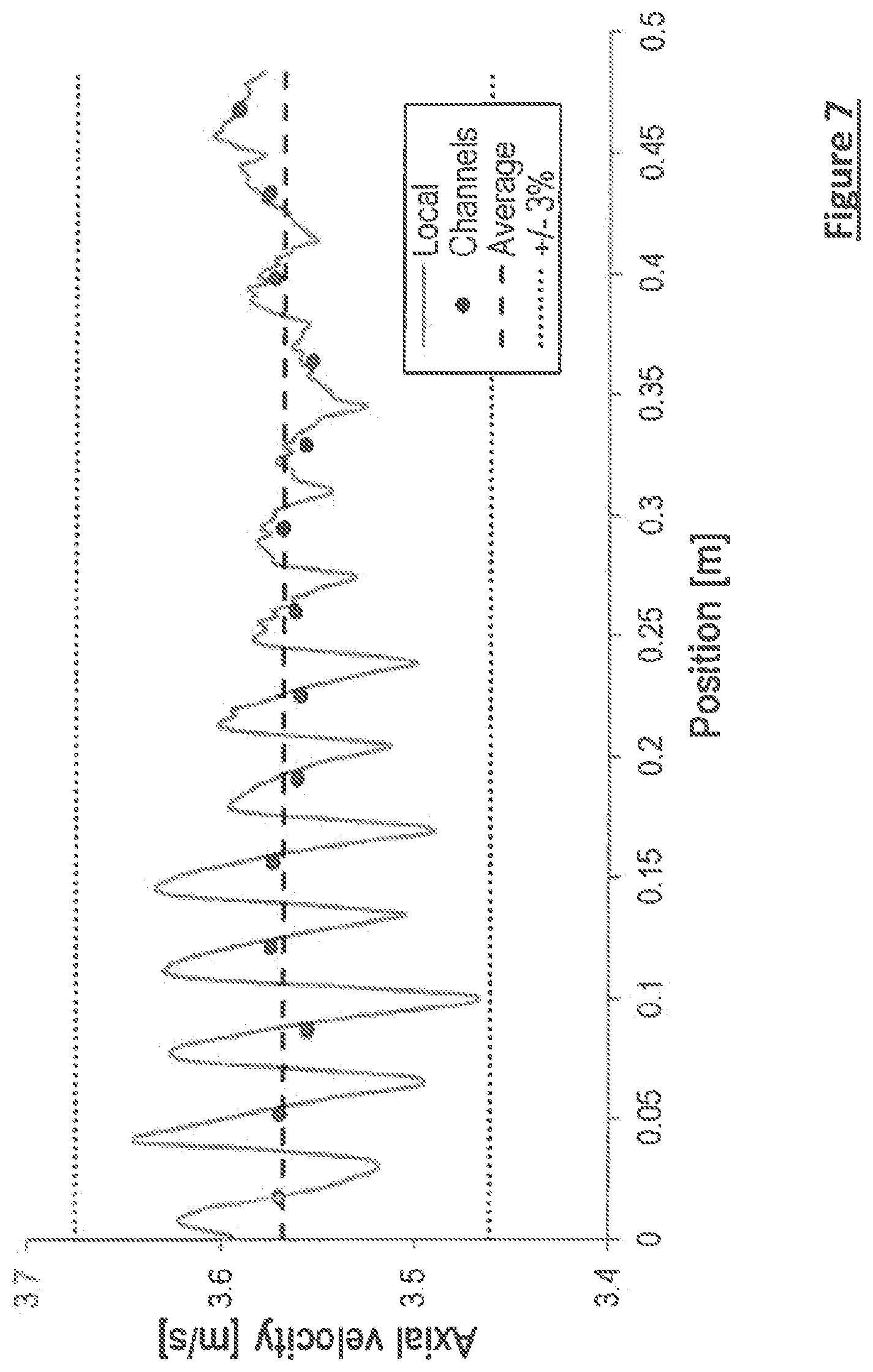
[0119] The results of these simulations are presented in FIGS. 6A, 6B, 6C and 7. FIGS. 6A, 6B and 6C show plots of the velocities, pressures and temperatures of the fluid flowing within the channels 26 of the distribution element 22. A quasi-homogeneous distribution of the fluid at the outlet of the channels 26 can be seen. FIG. 7 indicates the change in the values of what is known as the axial velocity, that is to say the velocity in the longitudinal direction z, that are obtained at the outlet of the element 22, depending on the position in the lateral direction y. The change thus starts from the center of the distribution element 22 (position at 0 mm) as far as the edge of the second end 23 (position at 485 mm). The distribution of the velocity values along the lateral direction y is characterized by a standard deviation of 0.9% and a maximum deviation of 2.8% with respect to the mean value of the velocity in the heat-exchange zone, this being much less than the variations found with the conventional distribution elements, for which the standard deviations are around 3%. By virtue of the invention, the velocity variations are thus reduced in the lateral direction at the outlet of the distribution zone, making it possible to distribute the fluid as homogeneously as possible across the entire width of the heat-exchange zone.
[0120] Of course, the invention is not limited to the particular examples described and illustrated in the present application. Other variants or embodiments within the competence of a person skilled in the art may also be considered without departing from the scope of the invention. For example, other directions and senses for the flow of the fluids in the heat exchanger are of course conceivable, without departing from the scope of the present invention. A distribution element according to the invention may thus be arranged in any distribution zone of the heat exchanger, in one or more series of passages 3, 4, 5 of the heat exchanger, upstream and/or downstream of one or more of the headers of the heat exchanger. For example, FIG. 5B illustrates the case in which a heat-exchanger passage comprises two distribution elements according to the invention arranged on either side of the heat-exchange zone 21 (schematically depicted with a deliberately shortened length). It should also be noted that passages 3, 4, 5 of the heat exchanger can be formed equally well between two successive plates 2 and between a closure bar 6 of the heat exchanger and an immediately adjacent plate 2.
[0121] It will be understood that many additional changes in the details, materials, steps and arrangement of parts, which have been herein described in order to explain the nature of the invention, may be made by those skilled in the art within the principle and scope of the invention as expressed in the appended claims. Thus, the present invention is not intended to be limited to the specific embodiments in the examples given above.
* * * * *
D00000
D00001
D00002
D00003
D00004
D00005
D00006
D00007
D00008
D00009
XML
uspto.report is an independent third-party trademark research tool that is not affiliated, endorsed, or sponsored by the United States Patent and Trademark Office (USPTO) or any other governmental organization. The information provided by uspto.report is based on publicly available data at the time of writing and is intended for informational purposes only.
While we strive to provide accurate and up-to-date information, we do not guarantee the accuracy, completeness, reliability, or suitability of the information displayed on this site. The use of this site is at your own risk. Any reliance you place on such information is therefore strictly at your own risk.
All official trademark data, including owner information, should be verified by visiting the official USPTO website at www.uspto.gov. This site is not intended to replace professional legal advice and should not be used as a substitute for consulting with a legal professional who is knowledgeable about trademark law.