Impeller Having Primary Blades And Secondary Blades
LEE; Seungbae
U.S. patent application number 16/761530 was filed with the patent office on 2020-11-26 for impeller having primary blades and secondary blades. This patent application is currently assigned to AERONET INC.. The applicant listed for this patent is AERONET INC.. Invention is credited to Seungbae LEE.
| Application Number | 20200370562 16/761530 |
| Document ID | / |
| Family ID | 1000005051095 |
| Filed Date | 2020-11-26 |


View All Diagrams
| United States Patent Application | 20200370562 |
| Kind Code | A1 |
| LEE; Seungbae | November 26, 2020 |
IMPELLER HAVING PRIMARY BLADES AND SECONDARY BLADES
Abstract
Provided is an impeller including a first portion including a first hub and a plurality of primary blades each extending while being spaced an equal distance from each other along an outer circumference of the first hub and a second portion including a second hub coupled to a lower side of the first hub by using a projection-groove coupling manner and a plurality of secondary blades each extending while being spaced apart from each other along an outer circumference of the second hub. Here, when a projection angle between a leading edge (L.E.) and a trailing edge (T.E.) of each of the primary blades is .PHI..sub.1, and a projection angle between a leading edge (L.E.) and a trailing edge (T.E.) of each of the secondary blades is .theta.1, the projection angle .PHI..sub.1 and .theta..sub.1 includes an upstream angle .PHI..sub.1u and .theta..sub.1u and a downstream angle .PHI..sub.1d and .theta..sub.1d, at which the primary blade and the secondary blade overlap each other, and an angle .PHI..sub.1m and .theta..sub.1m at which the primary blade and the secondary blade do not overlap each other, and the projection angle .theta..sub.1 is less than the projection angle .PHI..sub.1 to satisfy an equation 0<.theta..sub.1<.PHI..sub.1 as a radius of each of the primary blade and the secondary blade goes from the hub to the edge.
| Inventors: | LEE; Seungbae; (Incheon, KR) | ||||||||||
| Applicant: |
|
||||||||||
|---|---|---|---|---|---|---|---|---|---|---|---|
| Assignee: | AERONET INC. Incheon KR |
||||||||||
| Family ID: | 1000005051095 | ||||||||||
| Appl. No.: | 16/761530 | ||||||||||
| Filed: | December 15, 2017 | ||||||||||
| PCT Filed: | December 15, 2017 | ||||||||||
| PCT NO: | PCT/KR2017/014809 | ||||||||||
| 371 Date: | May 5, 2020 |
| Current U.S. Class: | 1/1 |
| Current CPC Class: | F04D 29/30 20130101 |
| International Class: | F04D 29/30 20060101 F04D029/30 |
Foreign Application Data
| Date | Code | Application Number |
|---|---|---|
| Nov 7, 2017 | KR | 10-2017-0147057 |
| Dec 14, 2017 | KR | 10-2017-0171944 |
Claims
1. An impeller comprising: a first portion comprising a first hub and a plurality of primary blades each extending while being spaced an equal distance from each other along an outer circumference of the first hub; and a second portion comprising a second hub coupled to a lower side of the first hub by using a projection-groove coupling manner and a plurality of secondary blades each extending while being spaced apart from each other along an outer circumference of the second hub, wherein when a projection angle between a leading edge (L.E.) and a trailing edge (T.E.) of each of the primary blades is .PHI..sub.1, and a projection angle between a leading edge (L.E.) and a trailing edge (T.E.) of each of the secondary blades is .theta..sub.1, the projection angle .PHI..sub.1 and .PHI..sub.1 comprises an upstream angle 1.sub.1u and .theta..sub.1u and a downstream angle .PHI..sub.1d and .theta..sub.1d, at which the primary blade and the secondary blade overlap each other, and an angle .PHI..sub.1m and .theta..sub.1m at which the primary blade and the secondary blade do not overlap each other, and the projection angle .theta..sub.1 is less than the projection angle .PHI..sub.1 to satisfy an equation 0<.theta.1<.PHI..sub.1 as a radius of each of the primary blade and the secondary blade goes from the hub to the edge.
2. The impeller of claim 1, wherein the angles .theta..sub.1u and .theta..sub.1d of the secondary blade have magnitudes overlapping the primary blade so that a channel around a downstream of a negative-pressure surface of the primary blade is guided.
3. The impeller of claim 1, wherein the first hub comprises a plurality of first coupling projections, which are spaced apart from each other on a bottom surface thereof, and a plurality of first coupling grooves that are provided by the plurality of first coupling projections, the second hub comprises a plurality of second coupling projections, which are spaced apart from each other on a top surface thereof, and a plurality of second coupling grooves that are provided by the plurality of second coupling projections, the plurality of first coupling projections are coupled to the plurality of second coupling grooves, and the plurality of second coupling projections are coupled to the plurality of first coupling grooves.
4. The impeller of claim 3, wherein the plurality of first coupling projections are coupled to the plurality of second coupling grooves in a pressing manner, and the plurality of second coupling projections are coupled to the plurality of first coupling grooves in a pressing manner.
5. The impeller of claim 3, wherein the plurality of first coupling projections are coupled to the plurality of second coupling grooves by using an adhesive, and the plurality of second coupling projections are coupled to the plurality of first coupling grooves by using an adhesive.
6. The impeller of claim 1, wherein each of the first hub and the second hub has a band shape.
7. The impeller of claim 1, wherein the first and second hubs form a single cone shape when coupled to each other.
8. An impeller comprising: a first portion comprising a circular bottom plate, a hub protruding from a central portion of a top surface of the circular bottom plate, and a plurality of primary blades formed in a circumferential direction with respect to the hub while being spaced an equal distance from each other on the top surface of the circular bottom plate; and a second portion comprising a shroud having a band shape and a plurality of secondary blades spaced a distance from each other along a bottom surface of the shroud in an integrated manner, wherein when an inlet area between a negative-pressure surface of the primary blade and a pressure surface of the secondary blade is Ssu, an inlet area between the pressure surface of the primary blade and a negative-pressure surface of the secondary blade is Spu, a downstream area of a channel of the negative-pressure surface of the primary blade, which is an area at a downstream of each channel, is Ssd, and a downstream area of a channel of the pressure surface of the primary blade is Spd, an outlet angle of the secondary blade is equal to that of the primary blade, an inlet of the secondary blade is disposed at a position at which an S-shape is varied, and an inlet angle of the secondary blade allows a tangent line of a flow angle to coincide with a primary streamline of the channel.
9. The impeller of claim 8, wherein a leading edge (L.E.) of the secondary blade is disposed between channels having the same radial inlet so hat the areas Ssu and Spu are equal to each other.
10. The impeller of claim 8, wherein an outlet angle and an outlet position between channels are set by rotating a trailing edge (T.E.) of the secondary blade to be disposed between channels having the same radial outlet by using a leading edge (L.E.) of the secondary blade as a pivot point, thereby maintaining the areas Ssu and Ssd are similar to each other.
11. The impeller of claim 8, wherein the shroud has a band shape.
12. The impeller of claim 8, wherein a plurality of first coupling groove, to which lower edges of the plurality of secondary blades are inserted, are defined in the top surface of the bottom plate, and a plurality of second coupling groove, to which upper edges of the plurality of primary blades are inserted, are defined in the bottom surface of the shroud.
13. The impeller of claim 12, wherein the lower edges of the plurality of secondary blades are coupled to the plurality of first coupling grooves in a pressing manner, and the lower edges of the plurality of primary blades are coupled to the plurality of second coupling grooves in a pressing manner.
14. The impeller of claim 12, wherein the lower edges of the plurality of secondary blades are coupled to the plurality of first coupling grooves by using an adhesive, and the lower edges of the plurality of primary blades are coupled to the plurality of second coupling grooves by using an adhesive.
15. The impeller of claim 1, wherein the plurality of secondary blades each disposed between each of the primary blades are spaced different distances from each other along a rotation direction of the impeller.
16. The impeller of claim 8, wherein the circular bottom plate and the shroud are inclined in a flow downstream direction or formed in a horizontal direction.
17. The impeller of claim 16, wherein the circular bottom plate has an outer diameter less than an inner diameter of the shroud.
18. The impeller of claim 16, wherein the plurality of primary blades and the plurality of secondary blades are coupled to the circular plate and the shroud in an integrated manner.
19. The impeller of claim 8, wherein the plurality of secondary blades each disposed between each of the primary blades are spaced different distances from each other along a rotation direction of the impeller.
Description
CROSS-REFERENCE TO RELATED APPLICATIONS
[0001] This U.S. non-provisional patent application claims priority under 35 U.S.C. .sctn. 119 of Korean Patent Application No. 10-2017-0147057, filed on Nov. 7, 2017 and 10-2017-0171944, filed on Dec. 14, 2017, the entire contents of which are hereby incorporated by reference.
BACKGROUND
[0002] The present disclosure herein relates to an impeller, and more particularly, to an impeller performing blade flow control by disposing a plurality of secondary blades between a plurality of primary blades.
[0003] Researches on well-known fluid machinery such as a fan, a blower, and a pump have been continuously performed for the past several decades to make progress in design technique. In recent years, since requirements on noise reduction as well as performance are enhanced, and sizes of products are reduced, further higher level of design techniques are required to be developed.
[0004] A typical axial impeller applied to the fluid machinery exhibits performance thereof by using a pressure and a flow rate. Specifically, as illustrated in FIG. 1, a pressure difference (.DELTA.p) between an inlet and an outlet is formed such that while a fluid passes between blades 1, a streamline is bent along a curvature of the blade, and a pressure increases by a lift force. Thus, as the streamline is more bent along a blade camber line 3, a rotation velocity component is generated to increase a pressure.
[0005] However, when the streamline is extremely bent, flow separation progresses at an angle of .alpha..sub.2 instead of an angle of .alpha..sub.2' that is an angle of a trailing edge (T.E.) of the blade, and a deviation angle is generated as much as a difference between .alpha..sub.2 and .alpha..sub.2' (.alpha..sub.2-.alpha..sub.2' (=.delta.)). Here, as shown in mathematical equation 1 below, the deviation angle .delta. is a function of soildity (.sigma.=C/s) that is a ratio of a camber angle (.PHI..sub.c) at which the blade is bent, a blade chord (C), and a pitch (s) between the blades. That is, when the camber angle (.PHI..sub.c) increases, the deviation angle increases, and when the soildity increases, the deviation angle decreases to improve performance.
.delta. = .delta. 0 + ( m 0 .sigma. b ) .phi. c [ Mathematical equation 1 ] ##EQU00001##
[0006] Here, .delta..sub.0 is an air foil shape, mo is the soildity, and b is a constant determined according to an inlet flow angle (.alpha..sub.1).
[0007] The related art has been focused to lengthen the chord while generating great pressure increase through lift force increase by magnifying the camber angle as large as possible while preventing flow separation or reducing an outlet deviation angle through soildity increase by increasing the number of blades and reducing the pitch between the blades. However, when the chord is lengthened, the impeller increases in a rotation shaft direction, and the camber angle for increasing a pressure is restricted due to flow separation at a negative-pressure surface.
[0008] U.S. Publication Patent No. US 2014/0233178 A1 discloses an example of improving performance by reducing a deviation angle of a blade outlet and increasing soildity by using an effect of lengthened blade as a secondary blade initiates around a trailing edge (T.E.) of a primary blade. However, the above-described invention has a limitation in that a height of the impeller increases, a length of the primary blade increases as much as a length in which the primary blade and the secondary blade overlap, and a difference in performance is insignificant.
[0009] Korean Registered Patent No. 10-1342746 discloses a typical impeller having increasing soildity by installing a plurality of secondary blades between a plurality of primary blades to reduce a blade pitch. The above-described impeller has a disadvantage in that a portion in which primary blades overlap is removed due to difficulty of injection molding to cause reduction in lift force and noise increase.
[0010] FIG. 2 illustrates a flow angle and a blade of a backward centrifugal impeller 20. Mathematical equation 2 shows a relationship between pressure increase of the impeller and a work given by Euler equation.
.delta. = .delta. 0 + ( m .sigma. b ) .phi. c [ Mathematical equation 2 ] ##EQU00002##
[0011] Here, .eta.R is an efficiency of the impeller, i.e., a percentage (%) of substantial transfer energy except for a flow loss from theoretical voltage increase caused by internal flow with respect to theoretical transfer energy.
[0012] A flow discharged from the impeller in FIG. 2 does not flow along an outlet blade and generates slip. Here, if a slip coefficient is .mu. when a blade angle is .beta.2b,
.mu. - C .theta. 2 C .theta. 2 , ideal , ##EQU00003##
and a slip coefficient .mu.E is expressed as in mathematical equation 3 by using Stodola equation.
.mu. E = 1 - .pi. sin .beta. 2 N B ( 1 - C m 2 cot .beta. 2 U 2 ) [ Mathematical equation 3 ] ##EQU00004##
[0013] Here, N.sub.B is the number of blades, .beta..sub.2 is an outlet flow angle, U.sub.2 and C.sub.m2 are rotation velocity of an edge of the blade and a radial component of an absolute velocity of outlet flow, respectively. Referring to mathematical equations 2 and 3, a rotation component C.sub..theta.2 of an absolute velocity of an outlet necessarily increases in order to improve pressure transfer, and, to this end, a slip coefficient necessarily increases by increasing the number of blades as many as possible.
[0014] U.S. Publication Patent No. US 2009/0155048 A1 discloses an example of an effect of increasing the number of blades by installing split vanes, which are secondary blades rotating by using the same shaft as primary blades, between the primary blades in a centrifugal pump impeller. In a fan or a blower that requires flow rate increase instead of pressure increase unlike the centrifugal pump producing a great static pressure, since a ratio of a height to a diameter of the impeller is extremely greater than that of a pump, an upper portion of an impeller blade is necessarily covered by a typical shroud plate, or an outlet above the blade is necessarily covered by a circular plate having a narrow band shape to reinforce rigidity. However, this case has a difficulty in injection molding.
SUMMARY
[0015] The present invention provides an impeller in which a plurality of secondary blades are installed between primary blades without increasing a height of the impeller for performance improvement and noise reduction in the axial and centrifugal impeller. In case of the axial impeller, a blade deviation angle is reduced to improve performance, and a size of a blade wake flow is reduced, to reduce noises. In case of the centrifugal impeller, as flow separation at a negative-pressure surface is reduced, performance improvement and reduction in flow separation noise are obtained through improvement of a slip constant.
[0016] An embodiment of the present invention provides an impeller including: a first portion including a first hub and a plurality of primary blades each extending while being spaced an equal distance from each other along an outer circumference of the first hub; and a second portion including a second hub coupled to a lower side of the first hub by using a projection-groove coupling manner and a plurality of secondary blades each extending while being spaced apart from each other along an outer circumference of the second hub. Here, when a projection angle between a leading edge (L.E.) and a trailing edge (T.E.) of each of the primary blades is .theta..sub.1, and a projection angle between a leading edge (L.E.) and a trailing edge (T.E.) of each of the secondary blades is .theta..sub.1, the projection angle .PHI..sub.1 and .theta..sub.1 includes an upstream angle .PHI..sub.1u and .theta..sub.1u and a downstream angle .PHI..sub.1d and .theta..sub.1d, at which the primary blade and the secondary blade overlap each other, and an angle .theta..sub.1m and .theta..sub.1m at which the primary blade and the secondary blade do not overlap each other, and the projection angle .theta..sub.1 is less than the projection angle .PHI..sub.1 to satisfy an equation 0<.theta..sub.1<.PHI..sub.1 as a radius of each of the primary blade and the secondary blade goes from the hub to the edge.
[0017] In an embodiment, the angles Om and Old of the secondary blade may have magnitudes overlapping the primary blade so that a channel around a downstream of a negative-pressure surface of the primary blade is guided.
[0018] In an embodiment, the first hub may include a plurality of first coupling projections, which are spaced apart from each other on a bottom surface thereof, and a plurality of first coupling grooves that are provided by the plurality of first coupling projections, the second hub may include a plurality of second coupling projections, which are spaced apart from each other on a top surface thereof, and a plurality of second coupling grooves that are provided by the plurality of second coupling projections, the plurality of first coupling projections may be coupled to the plurality of second coupling grooves, and the plurality of second coupling projections may be coupled to the plurality of first coupling grooves.
[0019] In an embodiment, the plurality of first coupling projections may be coupled to the plurality of second coupling grooves in a pressing manner, and the plurality of second coupling projections may be coupled to the plurality of first coupling grooves in a pressing manner
[0020] In an embodiment, the plurality of first coupling projections may be coupled to the plurality of second coupling grooves by using an adhesive, and the plurality of second coupling projections may be coupled to the plurality of first coupling grooves by using an adhesive.
[0021] In an embodiment, each of the first hub and the second hub may have a band shape.
[0022] In an embodiment, the first and second hubs may form a single cone shape when coupled to each other.
[0023] In an embodiment of the present invention, an impeller includes: a first portion including a circular bottom plate, a hub protruding from a central portion of a top surface of the circular bottom plate, and a plurality of primary blades formed in a circumferential direction with respect to the hub while being spaced an equal distance from each other on the top surface of the circular bottom plate; and a second portion including a shroud having a band shape and a plurality of secondary blades spaced a distance from each other along a bottom surface of the shroud in an integrated manner Here, when an inlet area between a negative-pressure surface of the primary blade and a pressure surface of the secondary blade is Ssu, an inlet area between the pressure surface of the primary blade and a negative-pressure surface of the secondary blade is Spu, a downstream area of a channel of the negative-pressure surface of the primary blade, which is an area at a downstream of each channel, is Ssd, and a downstream area of a channel of the pressure surface of the primary blade is Spd, an outlet angle of the secondary blade is equal to that of the primary blade, an inlet of the secondary blade is disposed at a position at which an S-shape is varied, and an inlet angle of the secondary blade allows a tangent line of a flow angle to coincide with a primary streamline of the channel.
[0024] In an embodiment, a leading edge (L.E.) of the secondary blade may be disposed between channels having the same radial inlet so hat the areas Ssu and Spu are equal to each other.
[0025] In an embodiment, an outlet angle and an outlet position between channels may be set by rotating a trailing edge (T.E.) of the secondary blade to be disposed between channels having the same radial outlet by using a leading edge (L.E.) of the secondary blade as a pivot point, thereby maintaining the areas Ssu and Ssd are similar to each other.
[0026] In an embodiment, the shroud may have a band shape.
[0027] In an embodiment, a plurality of first coupling groove, to which lower edges of the plurality of secondary blades are inserted, may be defined in the top surface of the bottom plate, and a plurality of second coupling groove, to which upper edges of the plurality of primary blades are inserted, may be defined in the bottom surface of the shroud.
[0028] In an embodiment, the lower edges of the plurality of secondary blades may be coupled to the plurality of first coupling grooves in a pressing manner, and the lower edges of the plurality of primary blades may be coupled to the plurality of second coupling grooves in a pressing manner.
[0029] In an embodiment, the lower edges of the plurality of secondary blades may be coupled to the plurality of first coupling grooves by using an adhesive, and the lower edges of the plurality of primary blades may be coupled to the plurality of second coupling grooves by using an adhesive.
[0030] In an embodiment, the plurality of secondary blades each disposed between each of the primary blades may be spaced different distances from each other along a rotation direction of the impeller.
[0031] In an embodiment, the circular bottom plate and the shroud may be inclined in a flow downstream direction or formed in a horizontal direction.
[0032] In an embodiment, the circular bottom plate may have an outer diameter less than an inner diameter of the shroud.
[0033] In an embodiment, the plurality of primary blades and the plurality of secondary blades may be coupled to the circular plate and the shroud in an integrated manner
BRIEF DESCRIPTION OF THE FIGURES
[0034] The accompanying drawings are included to provide a further understanding of the inventive concept, and are incorporated in and constitute a part of this specification. The drawings illustrate exemplary embodiments of the inventive concept and, together with the description, serve to explain principles of the inventive concept. In the drawings:
[0035] FIG. 1 is a view for explaining design variables related to a flow between blades of a general axial impeller and design variables related to the blades;
[0036] FIG. 2 is a view for explaining design variables related to a blade of a typical backward centrifugal impeller and a flow angle;
[0037] FIG. 3 is an assembly perspective view illustrating an axial impeller according to an embodiment of the present invention;
[0038] FIG. 4 is an exploded perspective view simultaneously illustrating a bottom surface of a first portion and a top surface of a second portion of the axial impeller in FIG. 3;
[0039] FIG. 5 is a schematic view illustrating a flow around a blade of each of the axial impeller according to an embodiment of the present invention and a typical impeller in conjunction with a streamline;
[0040] FIG. 6 is a view illustrating a structure between a primary blade and a secondary blade of the axial impeller according to an embodiment of the present invention;
[0041] FIG. 7 is an assembly perspective view illustrating a centrifugal impeller according to another embodiment of the present invention;
[0042] FIG. 8 is an exploded perspective view simultaneously illustrating a bottom surface of a first portion and a top surface of a second portion of the centrifugal impeller in FIG. 7;
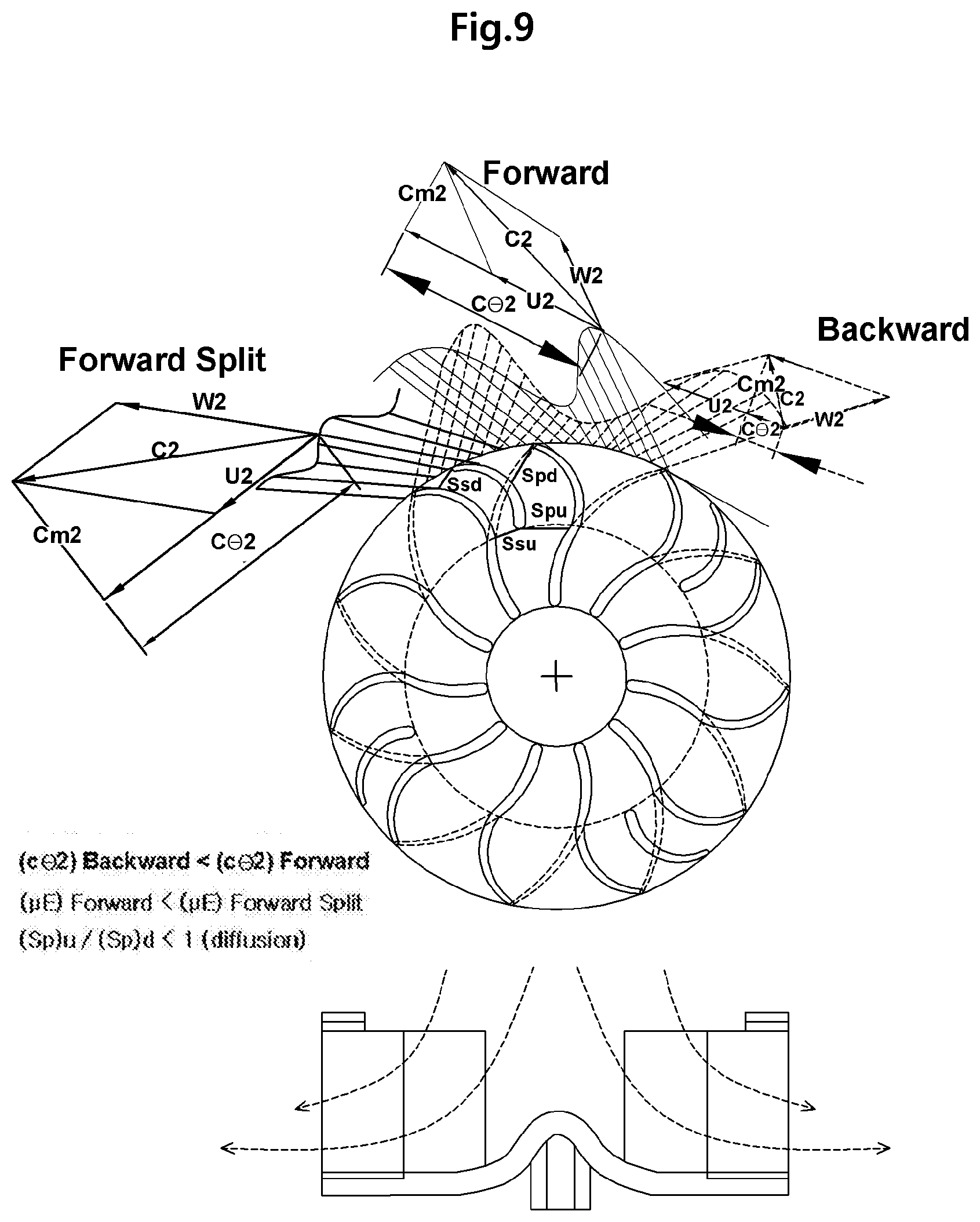
[0043] FIG. 9 is a view illustrating an example of a centrifugal impeller including a primary blade having a backward wake flow shape (expressed by a solid line) and a secondary blade having a split vane shape according to another embodiment of the present invention in conjunction with an example of a centrifugal impeller including a primary blade having a forward wake flow shape (expressed by a dotted line);
[0044] FIG. 10 is a cross-sectional view illustrating the primary blade and the secondary blade of the centrifugal impeller according to another embodiment of the present invention;
[0045] FIG. 11 is a view illustrating an example of randomly determining a position of the secondary blade of the centrifugal impeller between channels instead of determining the position as same as a rotation direction according to another embodiment of the present invention;
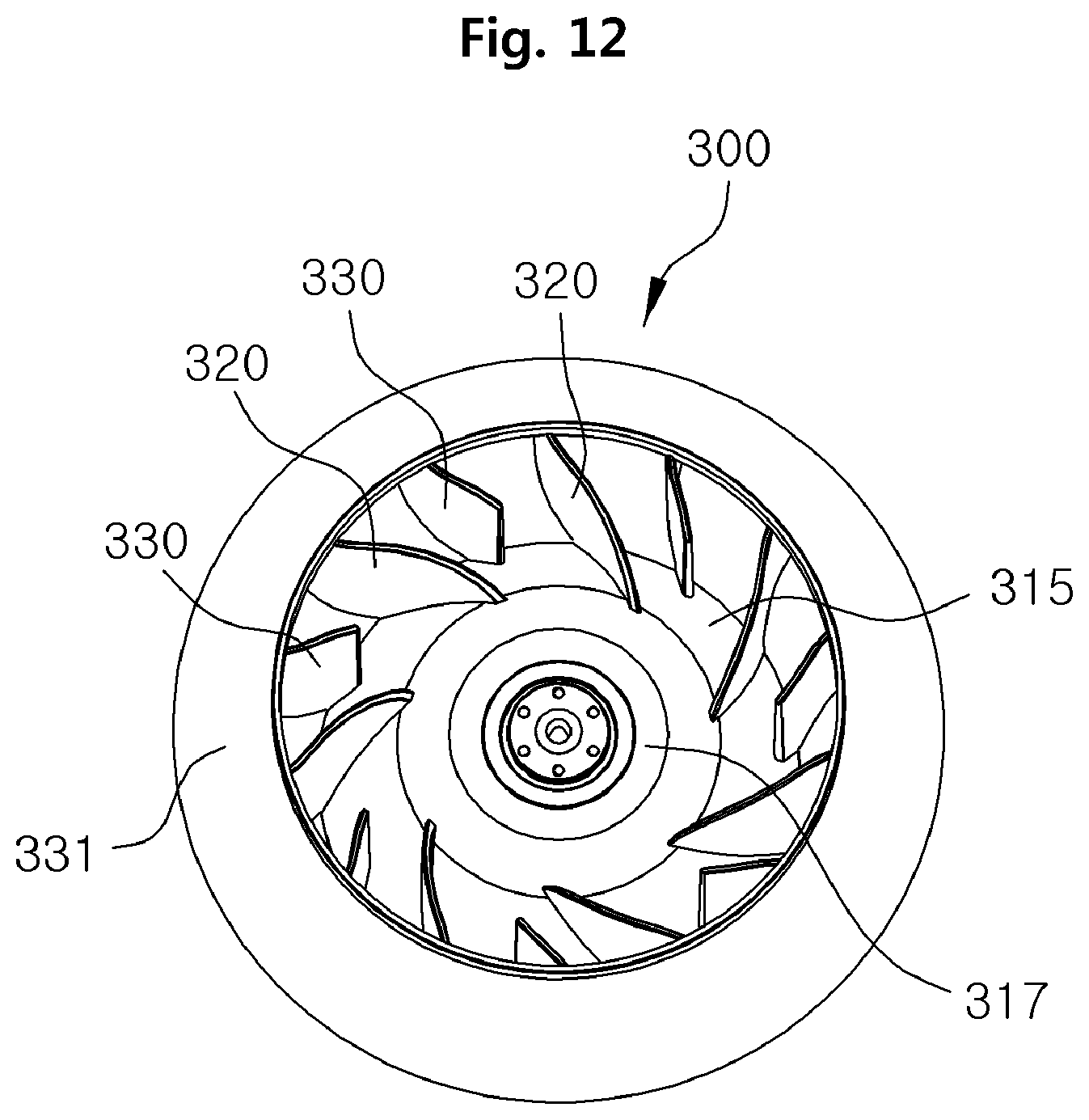
[0046] FIG. 12 is a perspective view illustrating an impeller including a mixed flow type primary blade and a secondary blade according to another embodiment of the present invention;
[0047] FIG. 13 is a plan view illustrating an impeller according to another embodiment of the present invention; and
[0048] FIG. 14 is a cross-sectional view taken along line A-A of FIG. 13.
DETAILED DESCRIPTION
[0049] Hereinafter, an axial impeller according to an embodiment of the present invention and a centrifugal impeller according to another embodiment will be sequentially described with reference the drawings.
[0050] FIG. 3 is an assembly perspective view illustrating an axial impeller according to an embodiment of the present invention, and FIG. 4 is an exploded perspective view simultaneously illustrating a bottom surface of a first portion and a top surface of a second portion of the axial impeller in FIG. 3.
[0051] Referring to FIG. 3, an axial impeller 100 according to an embodiment of the present invention includes a first portion 110 and a second portion 130, which are manufactured by separate components. The first portion 110 and the second portion 130, which are separately manufactured, are coupled to each other to be used as an impeller.
[0052] Referring to FIG. 4, the first portion 110 includes a first hub 111 having an approximately ring shape and a plurality of primary blades 120 spaced an equal distance from each other on an outer circumferential surface of the first hub 111.
[0053] The first hub 111 may have a hole 113 defined at a central portion thereof so as to be connected with a predetermined driving member such as a rotation shaft (not shown), thereby rotating the axial impeller 100.
[0054] Also, the first hub 111 includes a plurality of first coupling projections 115 protruding from a bottom surface thereof and spaced an equal distance from each other along the bottom surface. In this case, a plurality of coupling grooves 117 to which a plurality of second coupling projections 135 are inserted are provided between the first coupling projections 115.
[0055] Each of a plurality of primary blades 120 has one edge connected to the outer circumferential surface of the first hub 111 in an integrated manner and is gradually bent at a predetermined curvature in a direction toward the other edge thereof.
[0056] As in FIG. 4, each of the primary blades 120 includes a negative-pressure surface 121, a pressure surface 123 disposed opposite to the negative-pressure surface 121, a blade hub surface 125 disposed adjacent to the first hub 111, and a blade tip surface 127 disposed at an edge of the primary blade 120. In this case, each of the primary blades 120 has an upper edge that is defined as a leading edge (L.E.) and a lower edge that is defined as a trailing edge (T.E.).
[0057] The second portion 130 includes a second hub 131 having an approximately ring shape and a plurality of primary blades 140 spaced an equal distance from each other on an outer circumferential surface of the second hub 131.
[0058] Also, the second hub 131 may have a hole 133 defined at a central portion thereof like the first hub 111. In this case, the second hub 131 may have an outer diameter equal to that of the first hub 111 and an inner diameter equal to or less than that of the first hub 111. This structure may fix the impeller 100 to a rotation shaft or a rotating driving member corresponding to the rotation shaft.
[0059] Also, a plurality of second coupling projections 135 protrude from a top surface of the second hub 131 and are spaced an equal distance from each other along the top surface. In this case, a plurality of second coupling grooves 137 to which a plurality of first coupling projections 115 are inserted are provided between the second coupling projections 135.
[0060] As described above, the first and second hubs 111 and 131 are coupled to each other as the plurality of first coupling projections 115 are inserted to the plurality of second coupling grooves 137, and the plurality of second coupling projections 135 are inserted to the plurality of first coupling grooves 117. In this case, the first and second hubs 111 and 131 are coupled in a mutually pressing state or attached to each other by using a separate adhesive.
[0061] Each of the plurality of secondary blades 140 has one edge connected to an outer circumferential surface of the second hub 131 in an integrated manner and is gradually bent at a predetermined curvature in a direction toward the other edge thereof. Also, when the first and second hubs 111 and 131 are coupled to each other, the plurality of secondary blades 140 are disposed below the plurality of primary blades 120, respectively.
[0062] As in FIG. 4, each of the secondary blades 140 includes a negative-pressure surface 141, a pressure surface 143 disposed opposite to the negative-pressure surface 140, a blade hub surface 145 disposed adjacent to the second hub 131, and a blade tip surface 147 disposed at an edge of the secondary blade 140. In this case, each of the secondary blades 140 has an upper edge that is defined as a leading edge (L.E.) and a lower edge that is defined as a trailing edge (T.E.).
[0063] FIG. 5 is a schematic view illustrating a flow around a blade of each of the axial impeller according to an embodiment of the present invention and a typical impeller in conjunction with a streamline
[0064] Referring to FIG. 5A, when an incidence angle of an inlet is positive (+) (i.e., an inlet flow is incident toward a pressure surface more than a camber tangential direction of an inlet blade), as flow separation is generated above the negative-pressure surface S due to a camber of the blade, a streamline may not flow along the blade and be deviated toward the negative-pressure surface more than a camber tangential direction of a trailing edge of the blade. In this case, as a thick boundary layer flow processes due to the flow separation around the trailing edge of the blade, a thick wake flow of .delta.' is generated. In FIG. 5A, a reference symbol P represents the pressure surface of the blade.
[0065] In the present invention, the secondary blade 140 is disposed between two primary blades 120 as in FIG. 5B. Thus, when a channel flow having inlet areas A2 and A3 is formed, while an acceleration is rather generated around the inlet area A2, a flow separation is not generated at a downstream of the pressure surface 121 of the primary blade 120, unlike a case in FIG. 5A, in which a flow is decelerated from an inlet area A1 between primary blades to generate flow separation. Also, since a narrow wake thickness .delta.' is generated at the negative-pressure surface due to small-sized flow separation, and pressure increase is generated due to a blade camber as a deviation angle .delta. between channels is reduced, a camber angle greater than a case without the secondary blade may be applied.
[0066] FIG. 6 is a view illustrating a relationship between the primary blade and the secondary blade of the axial impeller according to an embodiment of the present invention.
[0067] Referring to FIG. 6, a first cylinder projection angle between the leading edge (L.E.) and the trailing edge (T.E.) of the primary blade 120 is .PHI.1, and a second cylinder projection angle between leading edge (L.E.) and the trailing edge (T.E.) of the secondary blade 140 is .theta.1.
[0068] Also, the first cylinder projection angle .PHI.1 includes an upstream angle .PHI.1u and a downstream angle .PHI.1d, which overlap the secondary blade 140, and an angle .PHI.1m not overlapping the secondary blade 140. Here, .PHI.1u=.theta.1d, and .PHI.1d=.theta.1u, and these values are varied as a blade radius goes from the hub to the edge. When .PHI.1=.theta.1, the number of the same blades becomes two times. Thus, in the present invention, an equation 0<.theta.1<.PHI.1 is satisfied, i.e., an angle gap of the secondary blade 140 is less than that of the primary blade 120, the trailing edge of the secondary blade 140 coincides with the trailing edge of the primary blade 120 so that a height of the impeller 100 (refer to FIG. 3) does not increase, and .theta.1u of the secondary blade is greater than .theta.1d so that a channel around a downstream of the negative-pressure surface 121 (refer to FIG. 4) of the primary blade 120 is sufficiently guided.
[0069] As described above, the first hub 111 and the second hub 131 are coupled to each other by the first and second coupling projections 115 and 135 and the first and second coupling grooves 117 and 137 as in FIG. 3. Here, the trailing edge of the primary blade 120 corresponding to the downstream angle .PHI.1d of the primary blade 120 is not attached to the first hub 111, but coupled with the second hub 132.
[0070] Although not shown in the drawing, each of the first and second hubs 111 and 131 may have a cone shape instead of the cylinder shape. For example, when the second hub 131 is coupled to a lower portion of the first hub 111, an overall integrated cone shape may be formed. As described above, the first and second hubs forming the cone shape may be used for a mixed flow impeller.
[0071] FIG. 7 is an assembly perspective view illustrating a centrifugal impeller according to another embodiment of the present invention, and FIG. 8 is an exploded perspective view simultaneously illustrating a bottom surface of a first portion and a top surface of a second portion of the centrifugal impeller in FIG. 7.
[0072] Referring to FIG. 7, a centrifugal impeller 200 impeller according to another embodiment of the present invention includes a first portion 210 and a second portion 230, which are components separately manufactured through injection molding, like the above-described axial impeller 100 according to an embodiment of the present invention The first portion 210 and the second portion 230 are coupled to each other to be used as an impeller.
[0073] Referring to FIG. 8, the first portion 210 includes a hub 211, a bottom plate 225 formed by a circular plate, and a plurality of primary blades 220 spaced an equal distance from each other.
[0074] The hub 211 may have a hole 213 defined at a central portion thereof so as to be connected with a predetermined driving member such as a rotation shaft (not shown), thereby rotating the centrifugal impeller 200. The hub 211 may have an approximately cone shape.
[0075] The hub 211 has a lower edge connected to a central portion of a top surface of the bottom plate 215 in an integrated manner. The plurality of primary blades 220 are spaced an equal distance from each other along a circumferential direction on the bottom plate 215, and lower edges of the plurality of primary blades 220 are connected to the top surface of the bottom plate 215 in an integrated manner.
[0076] Also, a plurality of first coupling grooves 217, to which lower edges of a plurality of secondary blades 240 that will be described later are inserted between neighboring primary blades 220, are defined in the top surface of the bottom plate 215.
[0077] Each of the plurality of primary blades 220 has a leading edge (L.E.) disposed adjacent to an outer circumferential surface of the first hub 211 and is gradually bent at a predetermined curvature in a direction from the leading edge (L.E.) to a trailing edge (T.E.).
[0078] Each of the primary blades 220 includes a negative-pressure surface 221, a pressure surface disposed opposite to the negative-pressure surface, a blade bottom surface 225 adjacent to the bottom plate 215, and a blade top surface 227 adjacent to a shroud 231 of the second portion 230, which will be described later. In this case, each of the primary blades 220 has an inside edge that is defined as a leading edge (L.E.) and an outside edge that is defined as a trailing edge (T.E.).
[0079] The second portion 230 includes a shroud 231 having an approximately ring shape and a plurality of secondary blades 240 spaced an equal distance from each other along a bottom surface of the shroud 231. In this case, each of the plurality of secondary blades 240 may have an arc shape or an S-shape.
[0080] The shroud 231 may have an outer diameter that is approximately equal to that of the bottom plate 215. Also, a plurality of second coupling grooves 233, to which the plurality of primary blades 220 are inserted, are defined between the plurality of secondary blades 240 in a bottom surface of the shroud 231. A portion of an upper edge of each of the plurality of primary blades 220 may be inserted to each of the plurality of second coupling grooves 233.
[0081] As described above, as lower edges of the plurality of secondary blades 240 are inserted to the plurality of first coupling grooves 217, respectively, and upper edges of the plurality of primary blades 220 are inserted to the second coupling grooves 233, respectively, the first and second portions 210 and 230 are coupled to each other. In this case, each of coupled portions are coupled in a mutually pressing manner or attached to each other by using a separate adhesive.
[0082] Each of the plurality of secondary blades 240 includes a negative-pressure surface 241, a pressure surface 243 disposed opposite to the negative-pressure surface, a blade bottom surface 245, and a blade top surface 247 adjacent to the shroud 231. In this case, each of the secondary blades 240 has an inside edge that is defined as a leading edge (L.E.) and an outside edge that is defined as a trailing edge (T.E.).
[0083] FIG. 9 is a view illustrating an example of a centrifugal impeller including a primary blade having a backward wake flow shape (expressed by a solid line) and a secondary blade having a split vane shape according to another embodiment of the present invention in conjunction with an example of a centrifugal impeller including a primary blade having a forward wake flow shape (expressed by a dotted line), and FIG. 10 is a cross-sectional view illustrating the primary blade and the secondary blade of the centrifugal impeller according to another embodiment of the present invention.
[0084] Referring to FIG. 9, the wake flow is expressed by a solid line when the primary blade of the centrifugal impeller has the backward wake flow shape, and the wake flow is expressed by a dotted line when the primary blade of the centrifugal impeller has the forward wake flow shape.
[0085] In this case, at a backward blade bent in a direction opposite to a rotation direction, a wide wake flow between blades caused by slip exists except for the pressure surface as expressed by a blue solid line. Also, at a forward blade bent in the same direction as the rotation direction, great flow separation is generated at the negative-pressure surface as an outlet of the primary blade is bent in the rotation direction as expressed by an orange solid line, and an energy loss of the wake is greater than that at an outlet of the blade at the backward blade. However, a pressure energy increase is relatively great as C.theta.2 of the above mathematical equation 2 increases, which is a relative velocity at the outlet in the rotation direction.
[0086] Although S-shaped hybrid blades are illustrated in FIG. 10 in order to use advantages of a high efficiency of the backward blade and a high pressure energy of the forward blade at the same time, as a channel is divided into two portions as in the axial impeller by installing the secondary blade called a split vane between the primary blades to overcome the great flow separation of the negative-pressure surface of the forward blade, slip and wake flow at the negative-pressure surface of the primary blade are reduced as expressed by a green solid line, and wake flow exists only at the negative-pressure surface of the secondary blade in conjunction with small flow separation. Thus, this flow type is the most preferable among three flow types.
[0087] In FIG. 9, reference symbols U2 and Cm2 are a rotation velocity of a blade edge and a radial component of an absolute velocity of an outlet flow, respectively, a reference symbol C.theta.2 is a rotation component of an outlet absolute velocity, and reference symbols C2 and W2 are a magnitude of an outlet absolute velocity vector and a magnitude of an outlet relative velocity vector, respectively.
[0088] Referring to FIG. 10, the channel of the hybrid blade installing the secondary blade includes: an inlet area Ssu (here, the suffix u represents the upstream) between the negative-pressure surface of the primary blade and the pressure surface of the secondary blade; an inlet area Spu between the pressure surface of the primary blade and the negative-pressure surface of the secondary blade; and an areas Ssd and Spd at each channel downstream. Since an inlet height and an outlet height of the blade are generally similar to each other, a flow separation is generated by pressure increase and velocity decrease as an outlet area increases more than an inlet area because a radius increases in a direction toward the blade downstream.
[0089] The present invention maintains an outlet angle of the secondary blade to be similar to an outlet angle .beta..sub.2b (refer to FIG. 2) of the primary blade and initiates an inlet of the secondary blade around a position at which the S-shape is varied, so that an inlet angle of the secondary blade allows a flow angle tangent line to coincide with a primary streamline between the channels in order to prevent the inlet area Ssu and the outlet area Ssd of the channel of the negative-pressure surface of the primary blade from being greatly varied. Also, since the area Ssu is less than the area Spu among the vertical areas of the channels although the secondary blade is disposed at a central portion of two primary blades, the leading edge (L.E.) of the secondary blade may move between channels having the same radial inlet so that the two areas are equal to each other, and as the leading edge (L.E.) of the secondary blade at the previously obtained position moves to a pivot point, and the trailing edge (T.E.) of the secondary blade moves between channels having the same radial outlet so that the area Ssu is similar to the area Ssd, an outlet angle and an outlet position between the channels may be determined.
[0090] FIG. 11 is a view illustrating an example of randomly determining a position of the secondary blade of the centrifugal impeller between channels instead of determining the position as same as a rotation direction according to another embodiment of the present invention.
[0091] The present invention randomly determines a position between the channels of the secondary blade of the centrifugal impeller as in FIG. 11 instead of determining the position as same as the rotation direction in order to cancel phases of a flow separation vortex above the negative-pressure surface of the secondary blade and a vortex passing through the channel In this case, the position may be determined so that a thrust and a torque balance of a shaft vertical surface are obtained by lift force distribution.
[0092] The centrifugal impeller 200 in FIG. 7 is obtained by coupling the first portion 210 and the second portion 230 to each other, and the first and second portions 210 and 230 are separately manufactured. However, the embodiment of the present invention is not limited thereto. For example, an impeller having an integrated body may be provided. Hereinafter, detailed description will be described with reference to FIGS. 12 to 14.
[0093] FIG. 12 is a perspective view illustrating an impeller including a mixed flow type primary blade and a secondary blade according to another embodiment of the present invention, FIG. 13 is a plan view illustrating an impeller according to another embodiment of the present invention, and FIG. 14 is a cross-sectional view taken along line A-A of FIG. 13.
[0094] Referring to FIGS. 12 to 14, an impeller 300 according to another embodiment of the present invention may be manufactured such that an outer diameter of a circular bottom plate 315 is slightly less than an inner diameter of a shroud 331 to inject a single body.
[0095] In this case, although all of the circular bottom plate 315 and the shroud 331 are formed inclined to a flow downstream direction as in FIG. 14, the embodiment of the present invention is not limited thereto. For example, all of the circular bottom plate 315 and the shroud 331 may be formed in a horizontal direction to be perpendicular to a rotation shaft direction.
[0096] Also, a plurality of primary blades 320 and a plurality of secondary blades 330 of the impeller 300 may be integrated with the shroud 331 and the circular bottom plate 315 or a hub 317 so as to be manufactured by using a single mold. That is, each of the plurality of primary blades 320 may have an upper edge connected to the shroud 331 and a lower edge connected to the circular bottom plate 315 or the hub 317. Also, each of the plurality of secondary blades 330 may have an upper edge connected to the shroud 331 and a lower edge connected to the circular bottom plate 315 or the hub 317.
[0097] In this case, the plurality of primary blades 320 and the plurality of secondary blades 330 may be alternately formed along a circumferential direction.
[0098] The axial impeller 200 in FIG. 7 operates such that a flow is introduced in a rotation shaft direction and then discharged in a radial direction perpendicular to the rotation shaft direction as a pressure increases. However, the mixed flow type impeller 300 in FIG. 12 operates such that a flow is introduced in a rotation shaft direction and then discharged in a direction inclined at a predetermined angle with respect to the rotation shaft direction as a pressure increases in a manner similar to the axial impeller. In this case, the mixed flow impeller 300 may form a flow path equal to the flow direction of the streamline in FIG. 14.
[0099] As described above, the impeller according to the present invention, in which the secondary blades are disposed between the primary blades, has an advantage with respect to each of the axial type and the centrifugal type as stated below.
[0100] In case of the axial impeller according to the present invention, effects of pressure increase and noise reduction may be obtained by reducing secondary flow at the negative-pressure surface of the main blade and reducing the deviation angle at the trailing edge of the blade. Also, when the plurality of secondary blades are disposed between the plurality of primary blades not to increase the height of the impeller, the first portion including the upper hub to which the plurality of primary blades are connected and the second portion including the lower hub to which the plurality of secondary blades are connected may be separately injection-molded, and the upper hub and the lower hub may each have a band shape having a circumferential radial thickness and be coupled to each other in the projection-groove coupling manner. Thus, a limitation of hardly separating upper and lower molds during the injection molding process because the blades overlap each other may be fundamentally resolved.
[0101] In case of the centrifugal impeller according to the present invention, effects of energy transfer increase and noise reduction may be obtained through reduction of blade slip by reducing the secondary flow at the negative-pressure surface of the primary blade having the backward and forward or radial combined hybrid S-shape. Also, as the first portion including the bottom plate to which the plurality of primary blades are attached and the second portion including the shroud having the band shape to which the plurality of secondary blades are attached are injection-molded as separate components, and the plurality of primary blades are coupled to the shroud in the projection-groove coupling manner, and the plurality of secondary blades are coupled to the bottom plate in the projection-groove coupling manner, a limitation generated during the injection molding may be resolved.
[0102] Although the exemplary embodiments of the present invention have been described, it is understood that the present invention should not be limited to these exemplary embodiments but various changes and modifications can be made by one ordinary skilled in the art within the spirit and scope of the present invention as hereinafter claimed. Hence, all changes, modifications, or alterations should therefore be seen as within the scope of the invention.
* * * * *
D00000
D00001
D00002
D00003
D00004
D00005
D00006
D00007
D00008
D00009
D00010


XML
uspto.report is an independent third-party trademark research tool that is not affiliated, endorsed, or sponsored by the United States Patent and Trademark Office (USPTO) or any other governmental organization. The information provided by uspto.report is based on publicly available data at the time of writing and is intended for informational purposes only.
While we strive to provide accurate and up-to-date information, we do not guarantee the accuracy, completeness, reliability, or suitability of the information displayed on this site. The use of this site is at your own risk. Any reliance you place on such information is therefore strictly at your own risk.
All official trademark data, including owner information, should be verified by visiting the official USPTO website at www.uspto.gov. This site is not intended to replace professional legal advice and should not be used as a substitute for consulting with a legal professional who is knowledgeable about trademark law.