Method Of No-bath Plasma Electrolytic Oxidation And Device For Implementing The Same
ZINIGRAD; Michael ; et al.
U.S. patent application number 16/992478 was filed with the patent office on 2020-11-26 for method of no-bath plasma electrolytic oxidation and device for implementing the same. This patent application is currently assigned to ARIEL SCIENTIFIC INNOVATIONS LTD.. The applicant listed for this patent is ARIEL SCIENTIFIC INNOVATIONS LTD.. Invention is credited to Konstantin BORODIANSKIY, Alexey KOSSENKO, Alexander KRASNOPOLSKY, Aleksandr SOBOLEV, Michael ZINIGRAD.
| Application Number | 20200370194 16/992478 |
| Document ID | / |
| Family ID | 1000005075185 |
| Filed Date | 2020-11-26 |


| United States Patent Application | 20200370194 |
| Kind Code | A1 |
| ZINIGRAD; Michael ; et al. | November 26, 2020 |
METHOD OF NO-BATH PLASMA ELECTROLYTIC OXIDATION AND DEVICE FOR IMPLEMENTING THE SAME
Abstract
An applicator for no-bath plasma gel electrolytic oxidation of a workpiece made of a valve metal or an alloy thereof; the applicator movable over a surface of a workpiece to be treated. The applicator including an electrode connectable to a power supply and configured for applying electric voltage to a gap between the electrode and a workpiece. A gel electrolytic medium body is mounted in a holder being in an electric contact with the electrode.
| Inventors: | ZINIGRAD; Michael; (Ramat Gan, IL) ; KRASNOPOLSKY; Alexander; (Petach Tikvah, IL) ; BORODIANSKIY; Konstantin; (Petach Tikvah, IL) ; SOBOLEV; Aleksandr; (Ariel, IL) ; KOSSENKO; Alexey; (Ashdod, IL) | ||||||||||
| Applicant: |
|
||||||||||
|---|---|---|---|---|---|---|---|---|---|---|---|
| Assignee: | ARIEL SCIENTIFIC INNOVATIONS
LTD. Ariel IL |
||||||||||
| Family ID: | 1000005075185 | ||||||||||
| Appl. No.: | 16/992478 | ||||||||||
| Filed: | August 13, 2020 |
Related U.S. Patent Documents
| Application Number | Filing Date | Patent Number | ||
|---|---|---|---|---|
| PCT/IL2019/050165 | Feb 12, 2019 | |||
| 16992478 | ||||
| 62629719 | Feb 13, 2018 | |||
| Current U.S. Class: | 1/1 |
| Current CPC Class: | C25D 11/005 20130101; C25D 21/02 20130101; C25D 17/06 20130101; C25D 17/10 20130101; C25D 21/12 20130101 |
| International Class: | C25D 11/00 20060101 C25D011/00; C25D 17/10 20060101 C25D017/10; C25D 21/12 20060101 C25D021/12; C25D 21/02 20060101 C25D021/02; C25D 17/06 20060101 C25D017/06 |
Claims
1. A method of no-bath plasma electrolytic oxidation of a workpiece made of a valve metal or an alloy thereof; the method comprising: deploying a workpiece to form a first electrode; providing an applicator of a gel electrolyte medium body to form a second electrode; said applicator comprising a receptacle of a member, made of said gel electrolyte medium body, facing said workpiece; mounting said gel electrolyte medium body within a holder; applying a voltage between said first electrode and said second electrode; contacting said gel electrolyte medium body to said workpiece.
2. The method according to claim 1, wherein said gel electrolyte medium body comprises a component selected from the group consisting of an acidic component, an alkaline component, a current amplifier component, a component improving thermal and electric conductivity, water and any combination thereof.
3. The method according to claim 2, wherein said alkaline component is potassium hydroxide, a gel forming component.
4. The method according to claim 2, wherein said current amplifier component is sodium silicate.
5. The method according to claim 2, wherein said gel electrolyte medium body comprises a gel forming component that is agar-agar.
6. The method according to claim 2, wherein gel electrolyte medium body comprises a gel forming component that is kappa carrageenan.
7. The method according to claim 2, wherein said component improving thermal and electric conductivity is selected from the group consisting of carbon nanoparticles, carbon nanotubes, metal particles and any combination thereof.
8. The method according to claim 1, wherein said second electrode comprises a passage conducting a coolant circulating therewithin.
9. An applicator for no-bath plasma gel electrolytic oxidation of a workpiece made of a valve metal or an alloy thereof; the applicator movable over a surface of a workpiece to be treated; the applicator comprising: an electrode connectable to a power supply and configured for applying electric voltage to a gap between said electrode and a workpiece; a gel electrolytic medium body mounted in a holder being in an electric contact with said electrode.
10. The applicator according to claim 9, wherein said gel electrolyte medium body comprises a component selected from the group consisting of an acidic component, an alkaline component, a current amplifier component, a component improving thermal and electric conductivity, water and any combination thereof.
11. The applicator according to claim 10 wherein said alkaline component is potassium hydroxide, a gel forming component.
12. The applicator according to claim 10, wherein said current amplifier component is sodium silicate.
13. The applicator according to claim 10, wherein said gel electrolyte medium body comprises a gel forming component that is agar-agar.
14. The applicator according to claim 10, wherein said gel electrolyte medium body comprises a gel forming component that is kappa carrageenan.
15. The applicator according to claim 10, wherein said component improving thermal and electric conductivity is selected from the group consisting of carbon nanoparticles, carbon nanotubes, metal particles and any combination thereof.
16. The applicator according to claim 9, wherein said electrode comprises a passage conducting a coolant circulating therewithin.
Description
CROSS-REFERENCE TO RELATED APPLICATIONS
[0001] This application is a continuation-in-part application of international application PCT/IL2019/050165 filed on Feb. 12, 2019, which claims priority from U.S. provisional application 62/629,719, filed on Feb. 13, 2018, the contents of each of which are incorporated herein by reference.
BACKGROUND OF THE INVENTION
Field of the Invention
[0002] This invention relates to surface treatment of workpieces made of valve metals and alloys thereof by means of plasma-electrolytic oxidation and, more specifically, to local plasma-electrolytic oxidation of outsized workpieces out of an electrolytic bath.
Background Information
[0003] Plasma electrolytic oxidation (PEO) is also known as micro-arc oxidation and spark anodizing is often regarded as a version of anodizing of valve metals (Mg, Al, Ti, and several others) and their alloys. Indeed, the essence of both anodizing and PEO is the production of oxide layers on a metal surface by the action of electricity in a convenient electrolyte. An oxide layer has a complex composition and includes various oxides of a base metal, alloy additives and species coming from the electrolyte. The part to be coated is immersed in a bath of electrolyte which usually constitutes a dilute alkaline such as KOH. The part to be coated is electrically connected and becomes one of the electrodes in the electrochemical cell, while the "counter-electrode" is typically made from an inert material such as stainless steel, and embodied as a wall of a electrolytic bath. Voltage over 200 V is applied between these two electrodes. Both direct and alternative potentials are applicable.
[0004] US Patent Application Publication No. 2012/031765, the entire contents of which are incorporated herein by reference, discloses a process for the corrosion protection of metals such as magnesium, aluminium or titanium, where at least two steps are used, including both plasma electrolytic oxidation and chemical passivation. The combination of these two processing steps enhances the corrosion resistance performance of the surface beyond the capability of either of the steps in isolation, providing a more robust protection system. This process may be used as a corrosion protective coating in its own right, or as a protection-enhancing pre-treatment for top-coats such as powder coat or e-coat. When used without an additional top-coat, the treated parts can still retain electrical continuity with and adjoining metal parts. Advantages include reduced cost and higher productivity than traditional plasma-electrolytic oxidation systems, improved corrosion protection, greater coating robustness and electrical continuity.
[0005] U.S. Pat. No. 6,585,875, the entire contents of which are incorporated herein by reference, discloses a process for treating an electrically conducting surface by arranging for the surface to form the cathode of an electrolytic cell in which the anode is maintained at a DC voltage in excess of 30V and an electrical arc discharge (electro-plasma) is established at the surface of the workpiece by suitable adjustment of the operating parameters, wherein the working gap between the anode and the cathode is filled with an electrically conductive medium consisting of a foam comprising a gas/vapor phase and a liquid phase. The process can be adapted for simultaneously coating the metal surface by including ions of the species required to form the coating in the electrically conductive medium. Apparatus for carrying out the process is also disclosed and, in particular, an anode assembly which comprises a perforated anode plate which is in communication with a chamber adapted to receive a flow of a liquid electrolyte, means to supply the liquid electrolyte to the chamber, and means to convert the liquid electrolyte received in the chamber into a foam.
[0006] Valve metals and alloys thereof are much used as structural materials in outsized or non-detachable article of vehicles, machinery and immovable facilities which cannot be placed into workshop environment. Hence, there is a long-felt and unmet need for protecting newly made outsized workpieces of valve metals and their alloys and repairing similar article having corrosion wear under field conditions.
SUMMARY OF THE INVENTION
[0007] It is hence one object of the invention to disclose a method of no-bath plasma electrolytic oxidation of a workpiece made of a valve metal or an alloy thereof. The aforesaid method includes the processes of: (a) deploying the workpiece to form a first electrode; (b) providing an applicator of an electrolyte medium to form a second electrode; (c) forming a working gap between the first and second electrodes; (d) applying a voltage between the first and second electrodes; (e) delivering the electrolyte medium into the working gap between the first and second electrodes.
[0008] It is a core purpose of the invention to provide the electrolyte medium selected from the group consisting of a foam electrolyte medium, a gel electrolyte medium, a pasteous electrolyte medium and any combination thereof.
[0009] Another object of the invention is to disclose the electrolyte medium including an acidic component.
[0010] A further object of the invention is to disclose the electrolyte medium including an alkaline component.
[0011] A further object of the invention is to disclose the alkaline component which is potassium hydroxide.
[0012] A further object of the invention is to disclose the electrolyte medium including a current amplifier component.
[0013] A further object of the invention is to disclose the current amplifier component which is sodium silicate.
[0014] A further object of the invention is to disclose the foam electrolyte medium including a viscosity and dispersion amplifier component.
[0015] A further object of the invention is to disclose the viscosity and dispersion amplifier component which is glycerin.
[0016] A further object of the invention is to disclose the foam electrolyte medium including a surfactant agent. A further object of the invention is to disclose the surfactant agent which is Triton-X100.
[0017] A further object of the invention is to disclose the foam electrolyte medium includes air.
[0018] A further object of the invention is to disclose the gel electrolyte medium including a gel forming component.
[0019] A further object of the invention is to disclose the gel forming component which is agar-agar.
[0020] A further object of the invention is to disclose the gel forming component which is kappa carrageenan.
[0021] A further object of the invention is to disclose the component improving thermal and electric conductivity selected from the group consisting of carbon nanoparticles, carbon nanotubes, metal particles and any combination thereof.
[0022] A further object of the invention is to disclose the second electrode including a passage conducting a coolant circulating therewithin.
[0023] A further object of the invention is to disclose the gel forming component which is kappa carrageenan.
[0024] A further object of the invention is to disclose the gel electrolyte medium including water.
[0025] A further object of the invention is to disclose the pasteous electrolyte medium including thickening agent.
[0026] A further object of the invention is to disclose the thickening agent which is carboxymethyl cellulose.
[0027] A further object of the invention is to disclose the pasteous electrolyte medium including water.
[0028] A further object of the invention is to disclose the step of delivering the electrolyte medium into the working gap including a step of generating a foam electrolyte medium.
[0029] A further object of the invention is to disclose the method including a step of draining a used foam electrolyte medium out of the working gap.
[0030] A further object of the invention is to disclose the step of delivering the electrolyte medium into the working gap performed in a close-loop manner.
[0031] A further object of the invention is to disclose the step of delivering the electrolyte medium into the working gap comprising a step of placing a gel electrolyte medium body within the working gap between the first and second electrodes.
[0032] A further object of the invention is to disclose the step of delivering the electrolyte medium into the working gap including spreading the pasteous electrolyte medium over a surface of the workpiece to be treated.
[0033] A further object of the invention is to disclose a foam electrolyte medium for no-bath plasma electrolytic oxidation of a workpiece made of a valve metal or an alloy thereof. The aforesaid foam electrolyte medium includes: (a) an acidic component; (b) a current amplifier component; (c) a viscosity and dispersion amplifier component; (d) a surfactant agent; and (e) air.
[0034] A further object of the invention is to disclose the foam electrolyte medium for no-bath plasma electrolytic oxidation of a workpiece made of an alloy metal or a valve thereof, the foam electrolyte medium including: (a) an alkaline component; (b) a current amplifier component; (c) a viscosity and dispersion amplifier component; (d) a surfactant agent; and (e) air.
[0035] A further object of the invention is to disclose a gel electrolyte medium for no-bath plasma electrolytic oxidation of a workpiece made of an alloy metal or a valve thereof. The aforesaid foam electrolyte medium includes: (a) an acidic component; (b) a current amplifier component; (c) a gel forming component; and (d) water.
[0036] A further object of the invention is to disclose a gel electrolyte medium for no-bath plasma electrolytic oxidation of a workpiece made of an alloy metal or a valve thereof. The aforesaid foam electrolyte medium includes: (a) an acidic component, (b) an alkaline component, (c) a current amplifier component, (c) a component improving thermal and electric conductivity and (d) water.
[0037] A further object of the invention is to disclose a pasteous electrolyte medium for no-bath plasma electrolytic oxidation of a workpiece made of a valve metal or an alloy thereof. The aforesaid foam electrolyte medium includes: (a) an acidic component; (b) a current amplifier component; (c) a thickening agent; and (d) water.
[0038] A further object of the invention is to disclose a pasteous electrolyte medium for no-bath plasma electrolytic oxidation of a workpiece made of an alloy metal or a valve thereof. The aforesaid foam electrolyte medium includes: (a) an alkaline component; (b) a current amplifier component; (c) a thickening agent; and (d) water.
[0039] A further object of the invention is to disclose an applicator for no-bath plasma electrolytic oxidation of a workpiece made of a valve metal or a valve thereof. The aforesaid applicator is movable over a surface of a workpiece to be treated. The applicator includes: (a) an electrode connectable to a power supply and configured for applying electric voltage to a gap between the electrode and the workpiece; and (b) electrolyte delivering means;
[0040] It is another core purpose of the invention to provide the electrolyte delivering means selected from the group consisting of: a generator of a foam electrolyte medium; a holder of a gel electrolyte medium, a dispenser of a pasteous electrolyte medium and any combination thereof.
[0041] A further object of the invention is to disclose the applicator including a drain pump configured for draining a used foam electrolyte medium out of the working gap.
[0042] A further object of the invention is to disclose the applicator including a working chamber attachable to the surface of the workpiece and accommodating the foam electrolyte medium being in an electric field created between the electrode and the workpiece.
[0043] A further object of the invention is to disclose the foam electrolyte medium generated by the generator and circulating via the working chamber in a close-loop manner.
[0044] A further object of the invention is to disclose the applicator including a holder configured for holding a gel electrolyte body made of the gel electrolyte medium such that the gel electrolyte medium body is positioned within the working gap between the first and second electrodes.
[0045] A further object of the invention is to disclose the applicator including a dispenser configured for spreading the pasteous electrolyte medium over a surface of the workpiece to be treated.
BRIEF DESCRIPTION OF THE DRAWINGS
[0046] In order to understand the invention and to see how it may be implemented in practice, a plurality of embodiments is adapted to now be described, by way of non-limiting example only, with reference to the accompanying drawings, in which
[0047] FIG. 1 is a flowchart of a method of no-bath plasma electrolytic oxidation of a workpiece made of a valve metal or an alloy thereof;
[0048] FIG. 2 is a general schematic diagram of an applicator for no-bath foam plasma electrolytic oxidation;
[0049] FIG. 3 is a schematic cross-sectional view of an applicator for no-bath foam plasma electrolytic oxidation;
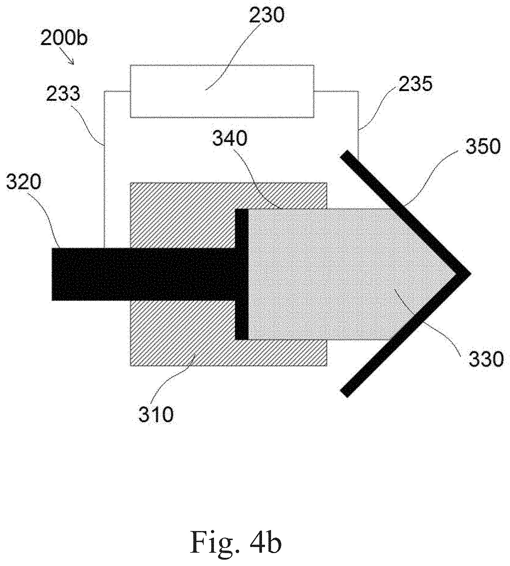
[0050] FIGS. 4a and 4b are schematic cross-sectional views of an applicator for no-bath gel plasma electrolytic oxidation; and
[0051] FIG. 5 is a schematic cross-sectional view of an applicator for no-bath pasteous plasma electrolytic oxidation.
DETAILED DESCRIPTION OF THE INVENTION
[0052] The following description is provided, so as to enable any person skilled in the art to make use of the invention and sets forth the best modes contemplated by the inventor of carrying out this invention. Various modifications, however, are adapted to remain apparent to those skilled in the art, since the generic principles of the present invention have been defined specifically to provide a method of no-bath plasma electrolytic oxidation of a workpiece made of a valve metal or an alloy thereof. Electrolytes and applicators for implementing the aforesaid method are also disclosed.
[0053] Reference is now made to FIG. 1 showing a method 100 of no-bath plasma electrolytic oxidation. Method 100 is directed to protection workpieces made of valve metals or their alloys. Method 100 is specifically applicable to outsized workpieces or non-detachable structural workpieces of vehicles, machinery and immovable facilities which cannot be placed into workshop environment. In accordance with the present invention, method 100 begins with step 110 of deploying a workpiece to form a first electrode. Specifically, the workpiece is electrically connected to a first terminal of a power supply. It should be emphasized that no need for placing the workpiece into an electrolytic bath. An applicator provided at step 120 has a second electrode connected to a second terminal of the power supply. In alignment with an electrolyte type, as any direct-current polarity of the first and second electrodes and alternative current are in the scope of the present invention. The first and the second electrodes are positioned at a predetermined distance such that a working gap therebetween is formed (step 130). A voltage between the first and the second electrodes is applied at step 140. In order to start the plasma electrolytic oxidation process per se, electrolytic medium is delivered into the working gap at step 150. The aforesaid electrolytic medium can alternatively include acidic or alkaline components. In addition, the electrolytic medium includes a current amplifier component such as sodium silicate and a viscosity-and-dispersion-amplifier component such as glycerin.
[0054] According to the first alternative embodiment of the present invention, a foam electrolytic medium is delivered at step 151. In addition to the common components (acidic or alkaline component, current amplifier component and viscosity-and-dispersion-amplifier component), the foam electrolytic medium includes a surfactant such as Triton-X100 and air.
[0055] According to the second alternative embodiment of the present invention, a gel electrolytic medium is delivered at step 152. Similar to the foam electrolytic medium, in addition to the common components, the gel electrolytic medium includes a gel forming component such as agar-agar or kappa carrageenan and water. Adding a component improving thermal and electric conductivity such as carbon nanoparticles, carbon nanotubes or metal particles are also in the scope of the present invention.
[0056] According to the third alternative embodiment of the present invention, a pasteous electrolytic medium is delivered at step 153. In addition to the common components, the pasteous electrolytic medium includes a thickening component such as Carboxymethyl cellulose and water.
[0057] The specific choice of the electrolyte components depends on the following parameters the plasma electrolytic oxidation: current and voltage provided by a power supply, thickness of the oxide coating to be obtained and characteristics of the obtained oxide coating.
[0058] Reference is now made to FIG. 2 presenting a general schematic diagram of applicator 200 for no-bath foam plasma electrolytic oxidation. Applicator 200 includes housing 205 having cavity (receptacle) 207 configured for accommodating (holding) an electrolytic medium (not shown) applicable to workpiece 209 to be coated. Power supply 230 controlled by control unit 231 provides difference of electric potentials between the aforesaid article and electrolytic medium. According to the present invention, a foam, a gel and a paste are usable as alternative electrolytic media.
[0059] Numerals 250 and 255 refer to a foam generator and a lockup valve which are optional components of applicator 200 when foam electrolytic medium is used.
[0060] Reference is now made to FIG. 3 presenting applicator 200a which is configured for no-bath plasma electrolytic oxidation with a foam electrolytic medium. Applicator 200a includes housing 210 having cavity 240 accommodating the foam electrolytic medium, which is fed by foam generator 250 into cavity 240 via pipe 253 and hollow electrode 220. It should be mentioned that in the current and further embodiments, the housing is made of an electrical insulating material. The electrostatic field is created between hollow electrode 220 (first electrode) and workpiece 260 (second electrode) which are electrically connected to supply 230 by wires 233 and 235. Spent foam electrolytic medium is withdrawn from cavity 240 via passage 245 and pipe 255. According to one embodiment of the present invention, applicator 200a includes a drain pump (not shown) for withdrawing the foam electrolytic medium in a forced manner.
[0061] Reference is now made to FIGS. 4a and 4b showing applicator 200b which is configured for no-bath plasma electrolytic oxidation with a gel electrolytic medium. Applicator 200b includes housing 310 having receptacle 340 configured for holding gel electrolytic medium body 330. The aforesaid body 330 is in an electric contact with electrode 320. According to one embodiment of the present invention, housing 310 has a passage (not shown) conducting a coolant circulating in the aforesaid passage. Terminals of power supply 320 are connected to electrode 320 and workpiece 350 by wires 233 and 235, respectively. It should be emphasized that sufficient elasticity of gel electrolytic medium body 330 enables treating any irregular surfaces having convex and concave elements shown in FIGS. 4a and 4b, respectively. Any geometry of the surface to be treated (including a flat surface) is in the scope of the present invention.
[0062] Reference is now made to FIG. 5 illustrating applicator 200c which is configured for no-bath plasma electrolytic oxidation with a pasteous electrolytic medium. Applicator 200c comprises housing 410 provided with electrode 420. Numeral 440 refers to a pasteous electrolytic medium which is a gap between aforesaid electrode 420 and workpiece 450 connected to power supply 230 by wires 233 and 235, respectively. Electrode 420 is placed within recess 430 to define a minimal gap between electrode 420 and workpiece 450 and prevent them from a shortcut.
[0063] Contrary to electrolytic bath technology where the workpiece is immersed within the electrolyte, in present invention, the applicator is moved over a surface of the workpiece in order to treat different areas of the workpiece surface.
[0064] It will be appreciated by those skilled in the art that changes could be made to the embodiments described above without departing from the broad inventive concept thereof. It is understood, therefore, that this invention is not limited to the particular embodiments disclosed, but it is intended to cover modifications within the spirit and scope of the present invention as defined by the appended claims.
* * * * *
D00000
D00001
D00002
D00003
D00004
D00005
D00006
XML
uspto.report is an independent third-party trademark research tool that is not affiliated, endorsed, or sponsored by the United States Patent and Trademark Office (USPTO) or any other governmental organization. The information provided by uspto.report is based on publicly available data at the time of writing and is intended for informational purposes only.
While we strive to provide accurate and up-to-date information, we do not guarantee the accuracy, completeness, reliability, or suitability of the information displayed on this site. The use of this site is at your own risk. Any reliance you place on such information is therefore strictly at your own risk.
All official trademark data, including owner information, should be verified by visiting the official USPTO website at www.uspto.gov. This site is not intended to replace professional legal advice and should not be used as a substitute for consulting with a legal professional who is knowledgeable about trademark law.