Biosynthetic Cannabinoid Production Methods
LEO; DANIEL MICHAEL
U.S. patent application number 16/990854 was filed with the patent office on 2020-11-26 for biosynthetic cannabinoid production methods. This patent application is currently assigned to INSECTERGY, LLC. The applicant listed for this patent is INSECTERGY, LLC. Invention is credited to DANIEL MICHAEL LEO.
| Application Number | 20200370073 16/990854 |
| Document ID | / |
| Family ID | 1000005058861 |
| Filed Date | 2020-11-26 |


View All Diagrams
| United States Patent Application | 20200370073 |
| Kind Code | A1 |
| LEO; DANIEL MICHAEL | November 26, 2020 |
BIOSYNTHETIC CANNABINOID PRODUCTION METHODS
Abstract
The present disclosure relates to the field of commercial scale production and processing of biosynthetic cannabinoids produced by growing genetically modified microalgae in a photo-bioreactor to a produce biosynthetic cannabinoids, separating a liquid nutrient medium from the genetically modified microalgae, and extracting the biosynthetic cannabinoids to produce an extracted biosynthetic cannabinoid, then distilling the extracted biosynthetic cannabinoid to produce the biosynthetic cannabinoid distillate. Biosynthetic cannabinoid distillates may be used foodstuffs, beverages, nanoemulsions, spray-dried water-soluble powders, cosmetics, or topicals.
| Inventors: | LEO; DANIEL MICHAEL; (Baltimore, MD) | ||||||||||
| Applicant: |
|
||||||||||
|---|---|---|---|---|---|---|---|---|---|---|---|
| Assignee: | INSECTERGY, LLC Baltimore MD |
||||||||||
| Family ID: | 1000005058861 | ||||||||||
| Appl. No.: | 16/990854 | ||||||||||
| Filed: | August 11, 2020 |
Related U.S. Patent Documents
| Application Number | Filing Date | Patent Number | ||
|---|---|---|---|---|
| 16153724 | Oct 6, 2018 | 10738268 | ||
| 16990854 | ||||
| 15841886 | Dec 14, 2017 | 10219536 | ||
| 16153724 | ||||
| 15664490 | Jul 31, 2017 | 10188086 | ||
| 15841886 | ||||
| 15257854 | Sep 6, 2016 | 10264769 | ||
| 15664490 | ||||
| 15242579 | Aug 21, 2016 | 10188083 | ||
| 15257854 | ||||
| Current U.S. Class: | 1/1 |
| Current CPC Class: | A23V 2002/00 20130101; A23L 33/105 20160801; A23P 10/40 20160801; A23L 2/52 20130101; B01D 3/14 20130101; C12P 7/22 20130101; A61K 8/9789 20170801 |
| International Class: | C12P 7/22 20060101 C12P007/22; A23L 33/105 20060101 A23L033/105; A23L 2/52 20060101 A23L002/52; A23P 10/40 20060101 A23P010/40; B01D 3/14 20060101 B01D003/14; A61K 8/9789 20060101 A61K008/9789 |
Claims
1. A method to produce a biosynthetic cannabinoid distillate, the method includes: (a) in a photo-bioreactor, growing microalgae which have been genetically modified to produce a biosynthetic cannabinoid, in a liquid nutrient medium; (b) separating the grown, genetically modified microalgae from the liquid nutrient medium; (c) extracting the biosynthetic cannabinoid from the grown, genetically modified microalgae to produce an extracted biosynthetic cannabinoid; and (d) distilling the extracted biosynthetic cannabinoid to produce the biosynthetic cannabinoid distillate.
2. The method according to claim 1, comprising: (e) producing a beverage from the biosynthetic cannabinoid distillate.
3. The method according to claim 1, wherein: (e) producing a nanoemulsion from the biosynthetic cannabinoid distillate.
4. The method according to claim 3, wherein: (f) spray drying the nanoemulsion to produce a spray-dried water-soluble powder.
5. The method according to claim 1, comprising: (e) mixing the biosynthetic cannabinoid distillate with cannabis plant derived terpenes.
6. The method according to claim 1, comprising: (e) mixing the biosynthetic cannabinoid distillate with non-biosynthetic plant derived cannabinoids.
7. The method according to claim 1, comprising: (e) producing a foodstuff from the biosynthetic cannabinoid distillate, the foodstuff includes one or more selected from the group consisting of ada, bagels, baked goods, beverages, biscuits, bitterballen, bonda, breads, cakes, candies, cereals, chips, chocolate bars, carbonated soft drinks, carbonated drinks, chocolate, coffee, cokodok, confectionery, cookies, cooking batter, corn starch mixtures, crackers, cr pes, croissants, croquettes, croutons, dolma, dough, doughnuts, energy bars, flapjacks, french fries, frozen custard, frozen desserts, frying cakes, fudge, gelatin mixes, granola bars, gulha, hardtack, ice cream, khandvi, khanom buang, krumpets, meze, mixed flours, muffins, multi-grain snacks, nachos, nian gao, noodles, nougat, onion rings, pakora, pancakes, panforte, pastas, pastries, pie crust, pita chips, pizza, poffertjes, pretzels, protein powders, pudding, rice krispie treats, sesame sticks, smoothies, snacks, soft drinks, sport drinks, sparkling drinks, specialty milk, tele-bhaja, tempura, toffee, tortillas, totopo, turkish delights, or waffles.
8. The method according to claim 1, comprising: (f) producing a cosmetic product or a topical from the biosynthetic cannabinoid distillate.
9. The method according to claim 1, wherein: the liquid nutrient medium includes treated water, the treated water is treated with an adsorbent, ion exchange resin, a membrane, and/or an ultraviolet unit.
10. The method according to claim 1, wherein: in step (a), introducing a gas to the liquid nutrient medium, the gas includes carbon dioxide.
11. The method according to claim 10, wherein: the photo-bioreactor operates at a superficial gas velocity less than 15 inches per second.
12. The method according to claim 1, wherein: in step (a), the liquid nutrient medium includes one or more selected from the group consisting of a carbohydrate, a micronutrient, a macronutrient, an acid, and combinations thereof.
13. The method according to claim 1, wherein: in step (a), growing the genetically modified microalgae within the photo-bioreactor at a residence time ranging from 1 to 5 days.
14. The method according to claim 1, wherein: in step (a), the photo-bioreactor operates at a photosynthetic photon flux density ranging from ranging from 50 to 1,000 micromole per second and square meter.
15. The method according to claim 1, wherein: in step (a), the photo-bioreactor is provided with a photon flux density source including one or more selected from the group consisting of compact fluorescent lights, incandescent lights, fluorescent lights, halogen lights, metal halide lamps, high-intensity discharge gas discharge lamps, low pressure sodium lamps, sodium lamps, quartz halogen lamps, and combinations thereof.
16. The method according to claim 1, wherein: in step (a), the photo-bioreactor is provided with a photon flux density source light emitting diodes, wherein the light emitting diodes operate at a wavelength ranging from 390 to 700 nanometers.
17. The method according to claim 1, wherein: in step (a), the photo-bioreactor is transparent and/or translucent.
18. The method according to claim 1, wherein: in step (a), the photo-bioreactor has a volume ranging from 50 to 2,000 liters.
19. The method according to claim 1, wherein: in step (d), distilling the extracted biosynthetic cannabinoid via spinning band distillation.
20. A method to produce a biosynthetic cannabinoid distillate, the method includes: (a) in a photo-bioreactor, growing microalgae and/or cyanobacterium which have been genetically modified to produce a biosynthetic cannabinoid, in a liquid nutrient medium and in the presence of carbon dioxide, the liquid nutrient medium including water treated with an adsorbent, ion exchange resin, and/or a membrane; (b) separating the grown, genetically modified microalgae and/or the genetically modified cyanobacterium from the liquid nutrient medium; and (c) extracting the biosynthetic cannabinoid from the grown, genetically modified microalgae and/or the genetically modified cyanobacterium to produce an extracted biosynthetic cannabinoid.
Description
RELATED APPLICATIONS
[0001] This application is a Continuation-In-Part of my now patented patent application Ser. No. 16/153,724, filed on Oct. 8, 2018, U.S. Pat. No. 10,738,268, issued on Aug. 11, 2020, which is a Continuation-In-Part of my now patented patent application Ser. No. 15/841,886, U.S. Pat. No. 10,219,536, filed on Dec. 14, 2017, and issued on Mar. 5, 2019, which is a Continuation-In-Part of my now patented patent application Ser. No. 15/664,490, filed on Jul. 31, 2017, U.S. Pat. No. 10,188,086, and issued on Jan. 29, 2019, which is a Continuation-In-Part of my now patented patent application Ser. No. 15/257,854, U.S. Pat. No. 10,264,769, filed on Sep. 6, 2016, and issued on Apr. 23, 2019, which is a Continuation-In-Part of my now patented patent application Ser. No. 15/242,579, U.S. Pat. No. 10,188,083, filed on Aug. 21, 2016, and issued on Jan. 29, 2019. The contents of the aforementioned applications are incorporated by reference in their entirety.
TECHNICAL FIELD
[0002] The present disclosure relates to the field of commercial scale production and processing of insects, cannabis, and biosynthetic cannabinoids to produce foodstuffs, consumer products, emulsions, drugs, pharmaceutical compositions, beverages, crystals, powders, softgels, surfactants, and oils, for medicinal or recreational, biotechnology, medical, and agrochemical applications.
BACKGROUND
[0003] Efficient, reliable, and consistent computer operated insect rearing facilities are needed to meet the insect production demands of society. In recent years, there has been an increasing demand for insect protein for human and animal consumption. There is also promise for the extraction and use of lipids from insects for applications involving medicine, nanotechnology, consumer products, and chemical production. Large scale insect production systems must be designed responsibly to make sure that the insects are freed from hunger, thirst, discomfort, pain, injury, disease, fear and distress. These systems must be precisely sized and situated to be able to provide systematically timed and controlled computer operated methods to maintain a sufficient amount of nutrition, to prevent disease, cannibalism, and injury. A need exists for mass insect production facilities that maximize insect production on a small physical outlay while providing adequate space for high density insect rearing.
[0004] The ability to grow insects with minimal human interaction has been long regarded as desirable or needed to facilitate widespread use for human and animal or consumption or for use as an intermediate lipid-based product for the production of food and chemicals. In coming years, nuclear proliferation, food shortages, water scarcity, and diminishing petroleum reserves may result in a constraint on access to food, water, chemicals, and other resources. Famine may result causing millions of deaths over an extended number of years which will mark a clear end to the period of growth and prosperity for the human civilization, industrialization, and globalization.
[0005] Thus, it is of paramount importance that large-scale, modular, easily manufacturable, energy efficient, reliable, computer operated insect production facilities are extensively deployed to produce insects for human and animal consumption, and for the extraction and use of lipids for applications involving medicine, nanotechnology, consumer products, and chemical production with minimal water, feedstock, and environmental impact.
[0006] There is a need for systems and methods that can clean and decontaminate water from the most-harshest of environmental conditions and provide a clean water source suitable to feed and grow insects for human, animal, and chemical production. There is a need to develop and vastly implement large-scale, systematic insect feeding and breeding facilities that can accommodate the protein and fatty acid demands of society. There is a need to re-use old containerized shipping containers to promote the implementation of widespread commercial production of insects to promote regional, rural, and urban, job opportunities that maximizes the quality of living the insects that are farmed.
[0007] A need exists for cannabis farming facilities that maximize plant production on a small physical outlay while providing adequate space for high-density plant growth all at an economically attractive cost. There is a need for systems and methods that can produce unique and novel foodstuffs or snack foods. There is a need for unique and novel foodstuffs or snack foods to be created from Orthoptera order of insects and produced from commercially available unit operations, including, feedstock mixing, enhanced feedstock splitting, insect feeding, insect breeding, insect collection, insect grinding, pathogen removal, multifunctional composition mixing, liquid mixing, shaping, cooking, flavoring, biocatalyst mixing, exoskeleton separation, liquid separation, and lipid extraction.
[0008] There is a need to make electrochemical biosensors made from insects for medicinal, environmental, agricultural, and food-related industrial market sectors. There is a need for insect pest management systems for cannabis farms. There is a need for an insect traceability system that is specifically tailored towards the unique challenges related to tracking, accountability, food safety, and state and federal government compliance of the insect industry, either for food (for humans or animals), drugs, chemicals, and medicine.
[0009] There is a need for systems to hydrogenate insect oil. There is a need for systems to produce distilled and purified insect oils There is a need for systems to esterify hydrogenated insect oil to make intermediate products for the production of consumer products including, baby lotion, biomedical sensing device, blush, body cream, candles, cleanser, cologne, concealer, food, foot powder, foot spray, foundation, hand cream, hard candy, lubricant, mascara, moisturizer, nail products, nano-device, oils, perfume, pharmaceuticals, powders, shaving cream, soap, surfactant, thickeners. There is a need for systems to process insect oil to produce intermediate products from stearic acid the intermediate product includes one or more intermediate products selected from the group consisting of glyceryl stearate, TEA-stearate, sorbitan stearate, and stearyl alcohol. There is a need to saponify insect oil to produce surfactants. There is a need to produce pharmaceutical compositions, including a cannabinoid, a recombinant protein, vaccine, antibody, peptide, or chemical and various other therapeutics and cosmetic personal products from insects using high-tech advancements in bioprocessing, chemical, and controls, and automation engineering technologies.
[0010] Efficient, reliable, and consistent, computer-operated cannabis farming systems and methods are needed to meet the cannabis production demands of society. In recent years, there has been an increasing demand for cannabis for medicinal and recreational use. Large-scale cannabis farming systems must be designed carefully to minimize environmental impact, reduce manual labor and human interaction, and automate the system as much as possible while maximizing plant growth. These systems must be precisely sized and situated to be able to provide systematically timed and controlled computer-operated methods to maintain a sufficient amount of water and nutrients for the cannabis at a precise temperature, humidity level, pH, oxygen and/or carbon dioxide level, air velocity, and light wavelength and schedule.
[0011] A need exists for an insect farm co-located at a cannabis farm to purposefully introduce insects into the cannabis plants to protect the plants allowing the insects to feed on other insect eggs, insect larva, and other insects including living organisms which may or may not contain chitin not only including spider mites, rust mites, thrips, jumping plant lice, white fly, knats, gnats, aphids, and insects. There is a need for computer-operated bat farms to protect cannabis plants within cannabis farms by purposefully introducing bats to the cannabis farm to feed on insects.
[0012] The ability to grow cannabis with minimal human interaction has been long regarded as desirable and needed to facilitate widespread use for human consumption and for the production of food. It is of importance that large-scale, standardized, modular, easily manufacturable, energy efficient, reliable, computer-operated cannabis farming systems and facilities are extensively deployed to produce cannabis for medicinal and recreation use with minimal water and environmental impact.
[0013] A need exists for an insect farm co-located at a mushroom farm to purposefully introduce insects into the mushroom plants to protect the plants allowing the insects to feed on other insect eggs, insect larva, and other insects including living organisms which may or may not contain chitin not only including spider mites, rust mites, thrips, jumping plant lice, white fly, knats, gnats, aphids, and insects. There is a need for computer-operated bat farms to protect mushroom plants within mushroom farms by purposefully introducing bats to the mushroom farm to feed on insects.
[0014] The ability to grow mushroom with minimal human interaction has been long regarded as desirable and needed to facilitate widespread use for human consumption and for the production of food. It is of importance that large-scale, standardized, modular, easily manufacturable, energy efficient, reliable, computer-operated mushroom farming systems and facilities are extensively deployed to produce mushroom for medicinal and recreation use with minimal water and environmental impact.
[0015] There is a need for cannabis farming facilities to employ systems and methods that can clean and decontaminate water from harsh and unpredictable sources and provide a clean water source suitable to feed and grow cannabis. There is a need to re-use old containerized shipping containers to promote the implementation of widespread commercial production of cannabis to promote regional, rural, and urban job opportunities that maximize the quality of living where the cannabis is farmed.
[0016] There is a need for a superior blend of Cannabis sativa L. ssp. Sativa and Cannabis sativa L. ssp. Indica (Lam.) that provides improved medicinal benefits, and has a high yield to meet industrial, commercial, recreational, and medicinal demand at a low price and minimal economic and environmental impact. There is a need for a new variety of plant that has a repeatable, predictable, and unique chemical composition that is based upon standardized engineered concentrations of: cannabidiol, tetrahydrocannabinol, energy, carbon, oxygen, hydrogen, ash, volatiles, nitrogen, sulfur, chlorine, sodium, potassium, iron, magnesium, phosphorous, calcium, zinc, cellulose, lignin, hemicellulose, fat, fiber, protein, while having preferred specific Cannabis sativa L. ssp. Sativa and Cannabis sativa L. ssp. Indica (Lam.) weight percentages.
SUMMARY
[0017] This Summary is provided merely to introduce certain concepts and not to identify any key or essential features of the claimed subject matter.
Paragraph A. A method to produce a biosynthetic cannabinoid distillate, the method includes: [0018] (a) in a photo-bioreactor, growing microalgae which have been genetically modified to produce a biosynthetic cannabinoid, in a liquid nutrient medium; [0019] (b) separating the grown, genetically modified microalgae from the liquid nutrient medium; [0020] (c) extracting the biosynthetic cannabinoid from the grown, genetically modified microalgae to produce an extracted biosynthetic cannabinoid; and [0021] (d) distilling the extracted biosynthetic cannabinoid to produce the biosynthetic cannabinoid distillate. Paragraph B. The method according to Paragraph A, comprising: (e) producing a beverage from the biosynthetic cannabinoid distillate. Paragraph C. The method according to Paragraph A, wherein: (e) producing a nanoemulsion from the biosynthetic cannabinoid distillate. Paragraph D. The method according to Paragraph C, wherein: (f) spray drying the nanoemulsion to produce a spray-dried water-soluble powder. Paragraph E. The method according to Paragraph A, comprising: (e) mixing the biosynthetic cannabinoid distillate with cannabis plant derived terpenes. Paragraph F. The method according to Paragraph A, comprising: (e) mixing the biosynthetic cannabinoid distillate with non-biosynthetic plant derived cannabinoids. Paragraph G. The method according to Paragraph A, comprising: (e) producing a foodstuff from the biosynthetic cannabinoid distillate, the foodstuff includes one or more selected from the group consisting of ada, bagels, baked goods, beverages, biscuits, bitterballen, bonda, breads, cakes, candies, cereals, chips, chocolate bars, carbonated soft drinks, carbonated drinks, chocolate, coffee, cokodok, confectionery, cookies, cooking batter, corn starch mixtures, crackers, cr pes, croissants, croquettes, croutons, dolma, dough, doughnuts, energy bars, flapjacks, french fries, frozen custard, frozen desserts, frying cakes, fudge, gelatin mixes, granola bars, gulha, hardtack, ice cream, khandvi, khanom buang, krumpets, meze, mixed flours, muffins, multi-grain snacks, nachos, nian gao, noodles, nougat, onion rings, pakora, pancakes, panforte, pastas, pastries, pie crust, pita chips, pizza, poffertjes, pretzels, protein powders, pudding, rice krispie treats, sesame sticks, smoothies, snacks, soft drinks, sport drinks, sparkling drinks, specialty milk, tele-bhaja, tempura, toffee, tortillas, totopo, turkish delights, or waffles. Paragraph H. The method according to Paragraph A, comprising: (f) producing a cosmetic product or a topical from the biosynthetic cannabinoid distillate. Paragraph I. The method according to Paragraph A, wherein: [0022] the liquid nutrient medium includes treated water, the treated water is treated with an adsorbent, ion exchange resin, a membrane, and/or an ultraviolet unit. Paragraph J. The method according to Paragraph A, wherein: in step (a), introducing a gas to the liquid nutrient medium, the gas includes carbon dioxide. Paragraph K. The method according to Paragraph J, wherein: the photo-bioreactor includes a superficial gas velocity ranging from between 0.1 to 15 inches per second. Paragraph L. T The method according to Paragraph A, wherein: in step (a), the liquid nutrient medium includes one or more selected from the group consisting of a carbohydrate, a micronutrient, a macronutrient, an acid, and combinations thereof. Paragraph M. The method according to Paragraph A, wherein: The method according to claim 1, wherein: in step (a), growing the genetically modified microalgae within a photo-bioreactor at a residence time ranging from 1 to 5 days. Paragraph NM. The method according to Paragraph A, wherein: in step (a), the photo-bioreactor operates at a photosynthetic photon flux density ranging from ranging from 50 to 1,000 micromole per second and square meter. Paragraph O. The method according to Paragraph A, wherein: in step (a), the photo-bioreactor is provided with a photon flux density source including one or more selected from the group consisting of compact fluorescent lights, incandescent lights, fluorescent lights, halogen lights, metal halide lamps, high-intensity discharge gas discharge lamps, low pressure sodium lamps, sodium lamps, quartz halogen lamps, and combinations thereof. Paragraph P. The method according to Paragraph A wherein: in step (a), the photo-bioreactor is provided with a photon flux density source light emitting diodes, wherein the light emitting diodes operate at a wave length ranging from 390 to 700 nanometers. Paragraph Q. T The method according to Paragraph A, wherein: in step (a), the photo-bioreactor is transparent and/or translucent. Paragraph R. The method according to Paragraph A, wherein: in step (a), the photo-bioreactor has a volume ranging from 50 to 2000 liters. Paragraph S. The method according to Paragraph A, wherein: in step (d), distilling the extracted biosynthetic cannabinoid via spinning band distillation. Paragraph T. A method to produce an extracted biosynthetic cannabinoid, the method includes: [0023] (a) in a photo-bioreactor, growing microalgae and/or cyanobacterium which have been genetically modified to produce a biosynthetic cannabinoid, in a liquid nutrient medium and in the presence of carbon dioxide, the liquid nutrient medium including water treated with an adsorbent, ion exchange resin, and/or a membrane; [0024] (b) separating the grown, genetically modified microalgae and/or the genetically modified cyanobacterium from the liquid nutrient medium; and [0025] (c) extracting the biosynthetic cannabinoid from the grown, genetically modified microalgae and/or the genetically modified cyanobacterium to produce an extracted biosynthetic cannabinoid.
Volume I: Insect Production Superstructure System (IPSS), Description of the Drawings
[0026] Reference will now be made in detail to various embodiments of the disclosure. Each embodiment is provided by way of explanation of the disclosure, not limitation of the disclosure. In fact, it will be apparent to those skilled in the art that modifications and variations can be made in the disclosure without departing from the teaching and scope thereof. For instance, features illustrated or described as part of one embodiment to yield a still further embodiment derived from the teaching of the disclosure. Thus, it is intended that the disclosure or content of the claims cover such derivative modifications and variations to come within the scope of the disclosure or claimed embodiments described herein and their equivalents.
[0027] Additional objects and advantages of the disclosure will be set forth in part in the description which follows, and in part will be obvious from the description, or may be learned by practice of the claims. The objects and advantages of the disclosure will be attained by means of the instrumentalities and combinations and variations particularly pointed out in the appended claims.
[0028] The accompanying figures show schematic process flowcharts of preferred embodiments and variations thereof. A full and enabling disclosure of the content of the accompanying claims, including the best mode thereof to one of ordinary skill in the art, is set forth more particularly in the remainder of the specification, including reference to the accompanying figures showing how the preferred embodiments and other non-limiting variations of other embodiments described herein may be carried out in practice, in which:
[0029] FIG. 1A shows a simplistic block flow diagram of one embodiment of an Insect Production Superstructure System (IPSS) including the sequence steps of feedstock mixing (step A), feedstock splitting (step B), insect feeding (step C1, C2), insect breeding (step D), insect collection (step E), and insect grinding (step F).
[0030] FIG. 1B elaborates upon the non-limiting embodiment of FIG. 1 further including the sequence steps of pathogen removal (step G) and multifunctional composition mixing (step H).
[0031] FIG. 1C elaborates upon the non-limiting embodiment of FIG. 1 further including the sequence step of lipid extraction (step J).
[0032] FIG. 1D includes one non-limiting embodiment of an insect traceability system flow chart.
[0033] FIG. 2 shows a non-limiting embodiment of an enhanced feedstock mixing module (1000) including a feedstock distribution module (1A), mineral distribution module (1B), vitamin distribution module (1C), polymer distribution module (1D), water distribution module (1E), and an enhanced feedstock distribution module (1F).
[0034] FIG. 3 shows a non-limiting embodiment of an insect feeding module (2000) integrated with an insect evacuation module (3000) operating in a first mode of operation wherein the egg transfer system (244) of the insect feeding module (2000) is at a first state in a first retracted height (H1).
[0035] FIG. 4 shows one non-limiting embodiment of a network (220) of cells (219) for growing insects within a feeding chamber (200) of the insect feeding module (2000) shown in FIG. 3.
[0036] FIG. 5 elaborates upon the non-limiting embodiment of FIG. 3 but shows the insect feeding module (2000) operating in a second mode of operation wherein the egg transfer system (244) of the insect feeding module (2000) is at a second state at a second elevated height (H2) so as to permit insects (225) to lay eggs (259) within a provided breeding material (248).
[0037] FIG. 6 elaborates upon the non-limiting embodiment of FIG. 3 but shows the insect feeding module (2000) operating in a third mode of operation wherein the egg transfer system (244) of the insect feeding module (2000) is at a first state in a first retracted height (H1) so as to discontinue insects (225) from laying eggs (259) within the provided breeding material (248).
[0038] FIG. 7 elaborates upon the non-limiting embodiment of FIG. 3 but shows the insect feeding module (2000) and insect evacuation module (3000) operating in a fourth mode of operation wherein a vibration unit (214) is activated to permit the removal of insects (225) from the network (220) of cells (219) and wherein the insect evacuation module (3000) separates insects from gas while a vacuum is pulled on the insect feeding module (2000) via an insect evacuation fan (312)
[0039] FIG. 8 shows a non-limiting embodiment of an insect feeding module (2000) integrated with an insect evacuation module (3000) operating in a first mode of operation wherein a plurality of slats (341) of an egg transfer system (244) of the insect feeding module (2000) are in first closed state (341A).
[0040] FIG. 9 elaborates upon the non-limiting embodiment of FIG. 8 and shows breeding material (248) resting upon the surface of the plurality of slats (341) of the egg transfer system (244) so as to permit insects (225) to lay eggs (259) within the breeding material (248).
[0041] FIG. 10 elaborates upon the non-limiting embodiment FIG. 8 but shows the egg transfer system (244) in a second open state (341A) so as to permit egg-laden breeding material (248) to pass through the plurality of slats (341) while the vibration unit (214) is activated, some insects (225) may pass through the open slats (341) as well.
[0042] FIG. 11 shows a simplistic diagram illustrating an insect grinding module that is configured to grind at least a portion of the insects transferred from the insect evacuation module (3000).
[0043] FIG. 12A shows a simplistic diagram illustrating a lipid extraction module that is configured to extract lipids from at least a portion of the insects transferred from the insect evacuation module (3000) by use of at least one solvent.
[0044] FIG. 12B shows a simplistic diagram illustrating a lipid extraction module that is configured to extract lipids from at least a portion of the insects transferred from the insect evacuation module (3000) by using of no solvent by way of an expeller press.
[0045] FIG. 12C shows one non-limiting embodiment of a hydrogenation system (12C) configured to hydrogenate the insect lipids (1518, 1552) to produce hydrogenation insect lipids (12CC).
[0046] FIG. 12D shows one non-limiting embodiment of an esterification system (12D) configured to produce esterified insect lipids.
[0047] FIG. 13 shows a simplistic diagram illustrating a pathogen removal module that is configured to remove pathogens from at least a portion of the insects transferred from the insect evacuation module (3000).
[0048] FIG. 14A shows a simplistic diagram illustrating a multifunctional composition mixing module that is configured to generate a multifunctional composition from at least a portion of the insects transferred from the pathogen removal module and including the sequence steps or sub-modules including an insect distribution module (6A), fiber-starch distribution module (6B), binding agent distribution module (6C), density improving textural supplement distribution module (6D), moisture improving textural supplement distribution module (6E), multifunctional composition mixing module (6F).
[0049] FIG. 14B shows a simplistic diagram illustrating a multifunctional composition mixing module that is configured to generate a multifunctional composition as described in FIG. 14A however instead from at least a portion of the insects transferred from the insect grinding module.
[0050] FIG. 14C shows one non-limiting embodiment of a liquid mixing module (LMM) that is configured to mix water with multifunctional composition (6F23) provided from the multifunctional composition mixing module as shown in FIG. 14A or 14B.
[0051] FIG. 14D shows one non-limiting embodiment of a shaping module (14D) that is configured to shape the multifunctional composition and water mixture (C17) to produce a shaped multifunctional composition mixture (D10).
[0052] FIG. 14E shows one non-limiting embodiment of a cooking module (14E) that is configured to cook the shaped multifunctional composition mixture (D10) provided from the shaping module (14D) to form a cooked multifunctional composition mixture (E18A).
[0053] FIG. 14F shows one non-limiting embodiment of a flavoring module (14F) that is configured to flavor the cooked multifunctional composition mixture (E18A) provided from the cooking module (14E) to form a flavored multifunctional composition mixture (F10).
[0054] FIG. 14G shows one non-limiting embodiment of a biocatalyst mixing module (14G) that is configured to mix insects, water, biocatalyst, and optionally acid to create an insect liquid biocatalyst mixture (G09).
[0055] FIG. 14H shows one non-limiting embodiment of an exoskeleton separation module (14H) that is configured to remove the exoskeleton contained within the insect liquid biocatalyst mixture (G09). FIG. 14I shows one non-limiting embodiment of a liquid separation module (LSM) that is configured to remove liquid from the exoskeleton-depleted insect liquid mixture (H39) to provide an insect-depleted liquid mixture (I19) and insects (I46).
[0056] FIG. 14J shows one non-limiting embodiment of a liquid separation module (LSM) that is configured to remove liquid from the exoskeleton-depleted insect liquid mixture (H39) to produce a vaporized liquid (J22) and a stream of liquid-depleted insects (J10).
[0057] FIG. 14K shows one non-limiting embodiment of a liquid separation module (LSM) that is configured to remove liquid from an insect liquid mixture (H39) by use of a spray dryer (KAP).
[0058] FIG. 14K-1 shows one non-limiting embodiment of a co-current type of spray dryer (KAP) that may be used with the liquid separation module (LSM) described in FIG. 14K.
[0059] FIG. 14K-2 shows one non-limiting embodiment of a counter-current type of spray dryer (KAP) that may be used with the liquid separation module (LSM) described in FIG. 14K.
[0060] FIG. 14K-3 shows another non-limiting embodiment of a counter-current type of spray dryer (KAP) that may be used with the liquid separation module (LSM) described in FIG. 14K.
[0061] FIG. 14K-4 shows a non-limiting embodiment of a mixed-flow type of spray dryer (KAP) that may be used with the liquid separation module (LSM) described in FIG. 14K.
[0062] FIG. 14KK shows one non-limiting embodiment of an insect-derived-biosensor including a transducer and an insect-derived-biopolymer.
[0063] FIG. 14L shows a power production system (PPS) that is configured to generate electricity, heat, or steam for use in the Insect Production Superstructure System (IPSS).
[0064] FIG. 15 shows a simplistic diagram illustrating a plurality of feeding chambers (FC1, FC2, FC3) of an insect feeding module (2000) integrated within one common separator (300) of an insect evacuation module (3000).
[0065] FIG. 16 shows a simplistic diagram illustrating a plurality of separators (S1, S2, S3) integrated with one common feeding chamber (FC1), and wherein the feeding chamber (FC1) and second separator (S2) are in fluid communication with one common breeding chamber (BC), and wherein the breeding chamber (BC) is in fluid communication with one common breeding material and insect separator (SEPIA), and wherein the breeding material and insect separator (SEPIA) is in fluid communication with at least one of a plurality of feeding chambers (FC1, FC2, FC3).
[0066] FIG. 16A shown one embodiment of a plurality of separators (KGA, KGB, KGC) that are configured to pull a vacuum on a plurality of insect feeding chambers (FC1, FC2, FC3) and separate large insects (KGG), small insects (KGH), and particulates (KGI) therefrom while returning the small insects (KGH) back to the plurality of insect feeding chambers (FC1, FC2, FC3).
[0067] FIG. 17 shows a perspective view of one embodiment of a scalable portable modular Insect Production Superstructure System (IPSS) designed with: one enhanced feedstock mixing module (1000); three insect feeding modules (2000A, 2000B, 2000C); one insect evacuation module (3000); three insect breeding modules (4000A, 4000B, 4000C), and three insect separation modules (5000).
[0068] FIG. 18 shows a front view of one embodiment of an enhanced feedstock mixing module (1000) module including a feedstock distribution module (1A), mineral distribution module (1B), vitamin distribution module (1C), and a polymer distribution module (1D).
[0069] FIG. 19 shows a top view of one embodiment of an enhanced feedstock mixing module (1000) including a feedstock distribution module (1A), mineral distribution module (1B), vitamin distribution module (1C), and a polymer distribution module (1D).
[0070] FIG. 20 shows a first side view of one embodiment of an enhanced feedstock mixing module (1000).
[0071] FIG. 21 shows a front view of one embodiment of a water distribution module (1E).
[0072] FIG. 22 shows a top view of one embodiment of a water distribution module (1E).
[0073] FIG. 23 shows a first side view of one embodiment of a water distribution module (1E).
[0074] FIG. 24 shows a front view of one embodiment of an enhanced feedstock distribution module (1F).
[0075] FIG. 25 shows a top view of one embodiment of an enhanced feedstock distribution module (1F).
[0076] FIG. 26 shows a first side view of one embodiment of an enhanced feedstock distribution module (1F).
[0077] FIG. 27A shows a front view of one embodiment of an insect feeding module (2000, 2000A, 2000B, 2000C).
[0078] FIG. 28A shows a top view of one embodiment of an insect feeding module (2000, 2000A, 2000B, 2000C).
[0079] FIG. 27B shows a top view of one embodiment of an insect feeding module (2000, 2000A, 2000B, 2000C) including a plurality of feeding chambers provided in one shipping container conforming to the International Organization for Standardization (ISO) specifications.
[0080] FIG. 27C shows a top view of one embodiment of an insect feeding module (2000, 24000A, 2000B, 2000C) equipped with a humidity control unit (HCU).
[0081] FIG. 27D shows one non-limiting embodiment where the compressor (Q30) within the humidity control unit (HCU) is that of a thermal compressor (Q30) that accepts a source of steam.
[0082] FIG. 27E shows one non-limiting embodiment where the compressor (Q30) within the humidity control unit (HCU) is that of a thermal compressor (Q30) that accepts a source of steam.
[0083] FIG. 27F elaborates upon FIG. 27E and shows one non-limiting embodiment where the compressor (Q30) within the humidity control unit (HCU) is that of a thermal compressor (Q30) that accepts a source of heat, such as flue gas (FG1).
[0084] FIG. 28B shows a top view of one embodiment of an insect feeding module (2000, 2000A, 2000B, 2000C) including a plurality of feeding chambers provided in one shipping container conforming to the International Organization for Standardization (ISO) specifications.
[0085] FIG. 29 shows a first side view of one embodiment of an insect feeding module (2000, 2000A, 2000B, 2000C).
[0086] FIG. 30 shows a front view of one embodiment of an insect evacuation module (3000).
[0087] FIG. 31 shows a top view of one embodiment of an insect evacuation module (3000).
[0088] FIG. 32 shows a first side view of one embodiment of an insect evacuation module (3000).
[0089] FIG. 33 shows a front view of one embodiment of an insect breeding module (4000, 4000A).
[0090] FIG. 34 shows a top view of one embodiment of an insect breeding module (4000, 4000A).
[0091] FIG. 34A shows a top view of one embodiment of an insect breeding module (4000, 4000A, 4000B, 4000C) equipped with a humidity control unit (HCU).
[0092] FIG. 34B shows one non-limiting embodiment where the compressor (QQ30) within the humidity control unit (HCU) is that of a thermal compressor (QQ30) that accepts a source of steam.
[0093] FIG. 35 shows a first side view of one embodiment of an insect breeding module (4000, 4000A) at a cutaway section of the conveyor side view (CSV).
[0094] FIG. 36 shows a second side view of one embodiment of an insect breeding module (4000, 4000A) at a cutaway section of the conveyor side view (CSV).
[0095] FIG. 37 shows a front view of one embodiment of a hatched insect separation module (5000, 5000A).
[0096] FIG. 38 shows a top view of one embodiment of a hatched insect separation module (5000, 5000A).
[0097] FIG. 39 shows a first side view of one embodiment of a hatched insect separation module (5000, 5000A).
[0098] FIG. 40A shows Table 1 with upper and lower ranges of feedstock mineral enhancers, feedstock vitamin enhancers, feedstock polymer enhancers, and other `energy-Insect.RTM.` enhancers.
[0099] FIG. 40B shows one non-limiting example of process conditions within an Insect Production Superstructure System (IPSS).
[0100] FIG. 40C shows nutritional requirements of insects produced in an Insect Production Superstructure System (IPSS) that are fed an enhanced feedstock.
[0101] FIG. 41A shows one non-limiting embodiment of a method for raising Orthoptera order of insects.
[0102] FIG. 41B shows one non-limiting embodiment of another method for raising Orthoptera order of insects.
[0103] FIG. 42A shows one non-limiting embodiment of a method for raising Orthoptera order of insects.
[0104] FIG. 42B shows one non-limiting embodiment of another method for raising Orthoptera order of insects.
[0105] FIG. 43A shows one non-limiting embodiment of a method for raising Orthoptera order of insects.
[0106] FIG. 43B shows one non-limiting embodiment of another method for raising Orthoptera order of insects.
[0107] FIG. 44A shows one non-limiting embodiment of a method for raising Orthoptera order of insects.
[0108] FIG. 44B shows one non-limiting embodiment of another method for raising Orthoptera order of insects.
[0109] FIG. 45A shows one non-limiting embodiment of a method for raising Orthoptera order of insects to generate a multifunctional composition.
[0110] FIG. 45B shows one non-limiting embodiment of another method for raising Orthoptera order of insects to generate a multifunctional composition.
[0111] FIG. 46 shows one non-limiting embodiment of another method for raising Orthoptera order of insects to generate a multifunctional composition.
[0112] FIG. 47 shows one non-limiting embodiment of a method for raising Orthoptera order of insects for the separation of lipids contained within said insects.
[0113] FIG. 48 shows one non-limiting embodiment of another method for raising Orthoptera order of insects for the extraction of lipids FIG. 1A' depicts one non-limiting embodiment of a farming superstructure system (FSS) including a first water treatment unit (A1*), a second water treatment unit (A2*), a third water treatment unit (A3*), a common reservoir (500*), a pump (P1*), a plurality of vertically stacked growing assemblies (100*, 200*), a fabric (104*, 204*) that partitions each growing assembly (100*, 200*) into an upper-section (105*, 205*) and a lower-section (106*, 206*), a plurality of lights (L1*, L2*) positioned within the upper-section (105*, 205*) of each growing assembly.
[0114] FIG. 1B' depicts one non-limiting embodiment of a farming superstructure system (FSS) that includes a first growing assembly (100*) having a first growing medium (GM1*) and a second growing assembly (200*) having a second growing medium (GM2*).
[0115] FIG. 1C' depicts one non-limiting embodiment of a farming superstructure system (FSS) that includes a first growing assembly (100*) having a first growing medium (GM1*) and a second growing assembly (200*) having a second growing medium (GM2*) and the first growing assembly (100*) and second growing assembly (200*) are grown outdoors.
[0116] FIG. 1D' depicts one non-limiting embodiment general arrangement of a farming superstructure system (FSS) top-view that includes a first growing assembly (100*) and a second growing assembly (200*) each configured to grow plants (107*, 107A*, 107B*, 107C*, 20*7, 207A*, 207B*, 207C*).
[0117] FIG. 2' depicts one non-limiting embodiment of a farming superstructure system (FSS) including a first vertically stacked system (1500*) including a plurality of vertically stacked growing assemblies (100*, 200*) integrated with a first and second vertical support structure (VSS1*, VSS2*) wherein the first growing assembly (100*) is supported by a first horizontal support structure (SS1*) and a second growing assembly (200*) is supported by a second horizontal support structure (SS2*).
[0118] FIG. 3' depicts one non-limiting embodiment of a plurality of vertically stacked systems (1500*, 1500'*) including a first vertically stacked system (1500*) and a second vertically stacked system (1500'*), the first vertically stacked system (1500*) as depicted in FIG. 2', also both vertically stacked systems (1500*, 1500'*) are contained within an enclosure (ENC*) having an interior (ENC1*).
[0119] FIG. 4A' depicts one non-limiting embodiment of FIG. 3' wherein the enclosure (ENC*) is provided with a temperature control unit (TCU*) including an air heat exchanger (HXA*) that is configured to provide a temperature and/or humidity controlled air supply (Q3*) to the interior (ENC1*) of the enclosure (ENC*) which contains a plurality of vertically stacked systems (1500*, 1500'*).
[0120] FIG. 4B' depicts one non-limiting embodiment of FIG. 1B' and FIG. 4A' wherein the enclosure (ENC*) is provided with a temperature control unit (TCU*) including an air heat exchanger (HXA*) that is configured to provide a temperature and/or humidity controlled air supply (Q3*) to the interior (ENC1*) of the enclosure (ENC*) which contains a plurality of growing assemblies (100*, 200*).
[0121] FIG. 5A' depicts one non-limiting embodiment of FIG. 4A' wherein the temperature control unit (TCU*) of FIG. 4A' is contained within the interior (ENC1*) of the enclosure (ENC*) and coupled with a humidity control unit (HCU*).
[0122] FIG. 5B' depicts one non-limiting embodiment of FIG. 4B' and FIG. 5A' wherein the temperature control unit (TCU*) of FIG. 4B' is contained within the interior (ENC1*) of the enclosure (ENC*) and coupled with a humidity control unit (HCU*).
[0123] FIG. 5C' shows one non-limiting embodiment where the compressor (Q30*) within the humidity control unit (HCU*) is that of a thermal compressor (Q30*) that accepts a source of steam.
[0124] FIG. 5D' shows one non-limiting embodiment where the compressor (Q30*) within the humidity control unit (HCU*) is that of a thermal compressor (Q30*) that accepts a source of steam.
[0125] FIG. 5E' elaborates upon FIG. 5D' and shows one non-limiting embodiment where the compressor (Q30*) within the humidity control unit (HCU*) is that of a thermal compressor (Q30*) that accepts a source of heat, such as flue gas (FG1*)
[0126] FIG. 6' shows a front view of one embodiment of a plant growing module (PGM*) provided inside of a shipping container conforming to the International Organization for Standardization (ISO) specifications.
[0127] FIG. 7' shows a top view of one embodiment of a plant growing module (PGM*) provided inside of a shipping container conforming to the International Organization for Standardization (ISO) specifications.
[0128] FIG. 8' shows a first side view of one embodiment of a plant growing module (PGM*).
[0129] FIG. 9' shows a front view of one embodiment of a liquid distribution module (LDM*) provided inside of a shipping container conforming to the International Organization for Standardization (ISO) specifications and that is configured to provide a source of liquid to a plurality of plant growing modules (PGM*).
[0130] FIG. 10' shows a top view of one embodiment of a liquid distribution module (LDM*) provided inside of a shipping container conforming to the International Organization for Standardization (ISO) specifications and that is configured to provide a source of liquid to a plurality of plant growing modules (PGM*).
[0131] FIG. 11' shows a first side view of one embodiment of a liquid distribution module (LDM*).
[0132] FIG. 12' shows one non-limiting embodiment of a fabric (104*) used in a growing assembly (100), the fabric (104) having a multi-point temperature sensor (MPT10*0) connected thereto for measuring temperatures at various lengths along the sensor's length.
[0133] FIG. 13' shows another one non-limiting embodiment of a fabric (104*) used in a growing assembly (100).
[0134] FIG. 14' depicts a computer (COMP) that is configured to input and output signals listed in FIGS. 1-17K'.
[0135] FIG. 15' shows a plurality of cannabis trimmers (TR*, TR**) that are configured to trim at least a portion of the cannabis (107*, 207*) that was growing in each growing assembly (100*, 200*).
[0136] FIG. 16' shows a grinder (GR*) that is configured to grind at least a portion of cannabis plants (107, 207*) that was growing in each growing assembly (100*, 200*).
[0137] FIG. 17' shows a heater (HTR1*) that is configured to heat at least a portion of cannabis plants (107*, 207*) that was growing in each growing assembly (100*, 200*).
[0138] FIG. 17A' shows one non-limiting embodiment of a volatiles extraction system (VES*) that is configured to extract volatiles from cannabis (107*, 207*) with a first solvent (SOLV1*).
[0139] FIG. 17A'' shows one non-limiting embodiment of a volatiles extraction system (VES*) that is configured to extract volatiles from cannabis (107*, 207*) with a chilled ethanol separation system (CESS).
[0140] FIG. 17B' shows a plurality of volatiles extraction systems (VES1*, VES2*) equipped with one first solvent separation system (SSS*).
[0141] FIG. 17C' shows a volatiles and solvent mixing system (VSMS*) that is configured to mix the volatiles (VOLT*) with a second solvent (SOLV2*).
[0142] FIG. 17D' shows a separation system (SEPSOL*)separation system (SEPSOL*) that is configured to separate at least a portion of the solvent (SOLV2*) from the volatiles and solvent mixture (SVSM*) to produce concentrated volatiles (CVOLT*).
[0143] FIG. 17D'' shows a plurality of sequential separation systems (SEPSOL*, SEPSOL**, SEPSOL***) that are configured to separate at least a portion of the solvent, volatiles, and/or cannabinoids from produce concentrated volatiles (CVOLT*) and a plurality of different compounds (1SCM*, 1SCM**, 2SCM*, 2SCM**)
[0144] FIG. 17E' shows one non-limiting embodiment of a solvent separation system that is configured to evaporator the second solvent from the volatiles and solvent mixture (SVSM*) by use of a spray dryer (KAP*).
[0145] FIG. 17E-1' shows one non-limiting embodiment of a co-current type of spray dryer (KAP*) that may be used with the solvent separation system described in FIG. 17E'.
[0146] FIG. 17E-2' shows one non-limiting embodiment of a counter-current type of spray dryer (KAP*) that may be used with the solvent separation system described in FIG. 17E'.
[0147] FIG. 17E-3' shows another non-limiting embodiment of a counter-current type of spray dryer (KAP*) that may be used with the solvent separation system described in FIG. 17E'.
[0148] FIG. 17E-4' shows one non-limiting embodiment of a mixed-flow type of spray dryer (KAP*) that may be used with the solvent separation system described in FIG. 17E'.
[0149] FIG. 17F' shows a power production system (PPS*) that is configured to generate electricity, heat, or steam for use in the farming superstructure system (FSS).
[0150] FIG. 17G' shows one non-limiting embodiment of a carbon dioxide removal system (GAE*) that is configured to remove carbon dioxide from flue gas (LFP*) for use as a source of carbon dioxide (CO2*) in the farming superstructure system (FSS).
[0151] FIG. 17H' shows a cannabinoid extraction system including vessels, filters, pumps, piping connecting flow between vessels and adsorbers, valving, controllers, pressure regulators, metering equipment, flow control, and microprocessor equipment, their construction, implementation, and functionality.
[0152] FIG. 17J' shows one non-limiting embodiment of a cannabinoid emulsion mixing system (17J*).
[0153] FIG. 17K' shows one non-limiting embodiment of a cannabinoid softgel encapsulation system (17K*).
[0154] FIG. 18' shows a simplistic diagram illustrating a multifunctional composition mixing module that is configured to generate a multifunctional composition from at least a portion of Cannabis plants (107*, 207*) that was harvested from each growing assembly (100*, 200*).
[0155] FIG. 19' illustrates a single fully-grown DANLEO III plant.
[0156] FIG. 20' illustrates zoomed-in view of a budding or flowering plant.
[0157] FIG. 21' illustrates a single leaf of DANLEO III.
[0158] FIG. 22' illustrates a trimmed and dried bud (reproductive structure) of DANLEO III.
[0159] FIG. 23' shows a cannabis cloning assembly (CA*) that is configured to clone cannabis plants and/or DANLEO III (107*, 207*) that were growing in each growing assembly (100*, 200*).
FIG. 1A:
[0160] FIG. 1A shows a simplistic block flow diagram of one embodiment of an Insect Production Superstructure System (IPSS) including the sequence steps of feedstock mixing (step A), feedstock splitting (step B), insect feeding (step C1, C2), insect breeding (step D), insect collection (step E), and insect grinding (step F).
[0161] FIG. 1A shows a plurality of sequence steps of an Insect Production Superstructure System (IPSS) including, feedstock mixing (step A), feedstock splitting (step B), insect feeding chamber #1 (step C1), insect feeding chamber #2 (step C2), insect breeding (step D), insect collection (step E), and insect grinding (step F).
[0162] Step A involves feedstock mixing where feedstock may be mixed with one or more additives from the group consisting of water, minerals, vitamins, and polymer to form an enhanced feedstock. Additionally, other enhancers may be added to the feedstock such as niacin, taurine, glucuronic acid, malic acid, N-acetyl L tyrosine, L-phenylalanine, caffeine, citicoline, or insect growth hormones. Table 1 on FIG. 40 lists the types of additives and enhancers that may be mixed with a feedstock to generate an enhanced feedstock.
[0163] Generally, a feedstock may be characterized as agriculture residue, alcohol production coproducts, animal waste, bio-waste, compost, crop residues, energy crops, fermentation waste, meat, insects, fermentative process wastes, food processing residues, food waste, garbage, industrial waste, livestock waste, municipal solid waste, plant matter, poultry wastes, rice straw, sewage, spent grain, spent microorganisms, urban waste, vegetative material, wood waste, cannabis, waste cannabis from the Farming Superstructure System, fish, fish that are fed the insects grown in the IPSS.
[0164] Mixing of feedstock with additives or enhancers is discussed below in detail. Exact proportions of feedstock, additives, and enhancers may be precisely combined to form an enhanced feedstock that is suitable to grow insects in a manner that maximizes productivity, minimizes mortality, and maximizes animal welfare. It has been my realization that the enhanced feedstock mixtures, weigh ratios, proportions, ranges cited in Table 1 of FIG. 40 are those that maximize insect production in a minimal amount of space.
[0165] It also has been my realization that the enhancers listed herein are those, when fed to insects, may then subsequently fed to humans as energy-Insects.RTM., which are a specialized kind of edible insect that contains a dose of the stimulant caffeine, vitamins, and other functional ingredients. It has also been my realization that insects truly enjoy eating my inventive enhanced feedstock blend and it increases their quality of life. Although there is no evidence and no way of truly telling that insects have the cognitive ability to enjoy eating my proprietary enhanced feedstock blend, I certainly give them the benefit of the doubt.
[0166] It has also been my realization that mixing water with the feedstock profoundly benefits insects since it elevates their well-being by making it impossible for them not to fear from expiration from respiratory impairment from being drowned in or under a liquid. It is the totality of the features of the present application that provide the maximum benefit to society.
[0167] An enhanced feedstock transfer line (002) is discharged from feedstock mixing (step A) where it enters the feedstock splitting (step B). Step B feedstock splitting involves dividing the enhanced feedstock up into a plurality of enhanced feedstock steams. In embodiments, it may be advantageous to have a plurality of insect feeding chambers and only one feedstock mixing sequence step. This minimizes the capital intensity of the Insect Production Superstructure System (IPSS) to thus in turn permits a more lucrative return on investment (ROI). In some instances, Step B may not be required since only one feeding chamber is desired.
[0168] A first enhanced feedstock transfer line (004) and a second enhanced feedstock transfer line (006) are discharged from feedstock splitting (Step B) and are routed to insect feeding chamber #1 (step C1) and insect feeding chamber #2 (step C2). FIG. 1A discloses a plurality of feeding chamber steps (C1 and C2). Two feeding chambers are shown in FIG. 1A, however it is to be noted that only one may be utilized, or three (as depicted in FIG. 17), or more may be utilized as seen fit.
[0169] Although two feeding chambers are shown in FIG. 1A, it is to be noted that the egg-laying insects present therein may freely travel from one feeding chamber to another. This is evidenced by feeding chamber transfer line (008) which connects the insect feeding chamber #1 (step C1) with insect feeding chamber #2 (step C2). The plurality of feeding chambers and a passageways therebetween encourage egg-laying insects therein to express normal behavior by enabling mobility and relocation to a more suitable living environment. An insect may decide to up and relocate for any reason it chooses or no reason at all. In the event that one breeding chamber lacks sufficient amounts of enhanced feedstock, or is over-crowded, or contains diseased or cannibalistic insects, the insects may relocate to another feeding chamber to alleviate their discomfort, pain, injury, disease, and fear and distress.
[0170] Herein is disclosed an Insect Production Superstructure System (IPSS) that permits insects to have mobility and the opportunity to choose between different possible courses of action. Herein are disclosed advancements and better solutions that meet new requirements, unarticulated needs, or existing market needs in maximizing insect welfare, maximizing insect output on a minimal physical outlay, and benefit of large groups of people a high-value animal protein.
[0171] FIG. 1A shows a first egg-laden breeding material transfer line (020) and a second egg-laden breeding material transfer line (021) being mixed into a combined egg-laden breeding material transfer line (022) which is then in turn provided to insect breeding (step D).
[0172] Insect eggs are extracted from the plurality of breeding chambers and are provided to a breeding chamber where the eggs are incubated and hatched. Hatched insects are then provided to the plurality of insect feeding chambers (step C1 and C2) via a first feeding chamber hatched insect transfer line (024) and a second feeding chamber hatched insect transfer line (026), respectively. Thus, herein is disclosed a method to: (i) remove at least a portion of eggs laid by the egg-laying insects within the feeding chambers; (ii) incubate at least a portion of the removed eggs in a breeding chamber; (iii) hatch at least a portion of incubated eggs; and, (iv) introduce a portion of hatched insects back into the insect feeding chamber.
[0173] Generally, the innovative methods of the Insect Production Superstructure System (IPSS) and Farming Superstructure System (FSS) is more generally suited for insects including one or more selected from the group consisting of Anthocoridae, minute pirate bugs, pirate bugs, flower bugs, the genus Orius, omnivorous bugs, carnivorous bugs, Orthoptera order of insects, grasshoppers, crickets, katydids, weta, lubber, acrida, locusts, mites, spider mites, predatory mites, Neoseiulus Fallacis, genus of mites that are in the Phytoseiidae family, arthropods, hexapods, beetles, cicadas, beetles, nematodes, mealworms, cockroaches, bats, mammals of the order Chiroptera, yellow mealworm beetles, Tenebrio Molitor, Tetranychus Urticae, carnivorous arthropods, omnivorous arthropods, green lacewings, insects in the family Chrysopidae, insects in the order Neuroptera, mantidflies, black soldier flies, butterflies, larvae, fly larvae, insect larvae, arthropod larvae, black soldier fly larvae, Hermetia illucens, antlions, mosquitos, Colorado potato beetle, Leptinotarsa decemlineata, moths, moth larvae, diamondback moth, Plutella xylostella, moth species of the family Plutellidae and genus Plutella. Encarsia Formosa, Autographa californica, alfalfa looper, moths of the family Noctuidae, insects in the macrolepidopteran clade Rhopalocera from the order Lepidoptera, whitefly parasites, ladybugs, spiders, dragonflies, orb-weaving spiders, arachnids, Spodoptera frugiperda, members of the spider family Araneidae, praying mantis, arachnids, eight-legged arthropods, and six-legged arthropods.
[0174] Generally, the innovative methods of the Insect Production Superstructure System (IPSS) and Farming Superstructure System (FSS) is more generally suited for insects including one or more selected from the group consisting of lepidoptera, larvae of Lepidoptera, larvae of butterflies, silkworm (Bombyx mori), larvae of silkworm (Bombyx mori), cabbage looper moth (Trichoplusia ni), and larvae of cabbage looper moth (Trichoplusia ni).
[0175] In embodiments, the bats provide a source of guano which may be used in the growing medium to grow cannabis plants and/or psilocybin mushrooms. In embodiments, the insects provide a source of guano which may be used in the growing medium to grow cannabis plants and/or psilocybin mushrooms.
[0176] In embodiments, the bats provide a source of guano which may be used in the growing medium to grow the plants. In embodiments, the bats include bat from families including: Megadermatidae, Craseonycteridae, Rhinopomatidae, Hipposideridae, Rhinolophidae, Miniopteridae, Noctilionidae, Mormoopidae, Mystacinidae, Thyropteridae, Furipteridae, Mormoopidae, Phyllostomidae, Molossidae, Emballonuridae, Myzopodidae, Emballonuridae, Natalidae, Vespertilionidae, and combinations thereof.
[0177] In embodiments, the insects feed on insect eggs, insect larva, and other insects including living organisms which may or may not contain chitin not only including spider mites, rust mites, thrips, jumping plant lice, white fly, knats, gnats, aphids, and insects. In embodiments, the insects feed on thrips order Thysanoptera. In embodiments, the insects feed on Tetranychus Urticae. In embodiments, the insects feed on spider mites. In embodiments, the insects eat other insects that are found on the cannabis plants disclosed herein. In embodiments, the bats eat insects that are found on the cannabis plants disclosed herein.
[0178] Both the insect feeding chamber #1 (step C1) and insect feeding chamber #2 (step C2) are in fluid communication with insect collection (step E). The insect feeding chamber #1 (step C1) is in fluid communication with insect collection (step E) via a first feeding chamber insect transfer line (010). The insect feeding chamber #2 (step C2) is in fluid communication with insect collection (step E) via a second feeding chamber insect transfer line (012).
[0179] Insects may be collected from the insect feeding chambers in a number of ways. Some non-limiting embodiments of the present disclosure suggest removing the insects by vibrating the egg-laying insects from the feeding chamber. Some non-limiting embodiments of the present disclosure suggest removing the insects by conveying the egg-laying insects from the feeding chamber. Some non-limiting embodiments of the present disclosure suggest vacuuming the insects from the feeding chamber.
[0180] It is to be noted that all of the embodiments disclosed herein are non-limiting and as long as the insects are in fact removed from an insect feeding chamber by any conceivable means or method, the bounds of this application are deemed to have been infringed. Thus, it should be apparent, however, to those skilled in the art that many more modifications besides those already described are possible without departing from the inventive concepts herein related to removing insects from the feeding chamber. The inventive subject matter pertaining to removing insects from the feeding chambers, therefore, is not to be restricted to vibrating, conveying, vacuuming insects from the feeding chamber but instead extend to any possible means for achieving the end of removing insects from out of the interior of the feeding chamber.
[0181] In embodiments, the insect collection (step E) is in fluid communication with insect grinding (step F) via a combined collected insect transfer line (014). The insect grinding (step F) is configured to output ground insects via a ground insect transfer line (016).
FIG. 1B:
[0182] FIG. 1B elaborates upon the non-limiting embodiment of FIG. 1 further including the sequence steps of pathogen removal (step G) and multifunctional composition mixing (step H).
[0183] FIG. 1B shows a pathogen removal (step G) placed upstream of a multifunctional composition mixing (step H) step. In embodiments, the pathogen removal (step G) is configured to accept collected insects provided from the insect collection (step E) or insect grinding (step F). In embodiments, the pathogen removal (step G) is configured to accept collected insects provided from the insect collection (step E). In embodiments, the pathogen removal (step G) is configured to accept collected insects provided from the insect grinding (step F) as seen in FIG. 13 as accepting ground separated insects (1500). However, it is to be noted that grinding need not take place in order for pathogen to be removed from collected insects. As seen in the non-limiting embodiment of FIG. 1B, pathogen removal (step G) only places after insect collection (step E) and after insect grinding (step F). However, it is not necessary that grinding takes place in between insect collection (step E) and pathogen removal (step G).
[0184] Pathogen removal (step G) is optional. In embodiments, the insects are heated before they are reduced in size by grinding. In embodiments, the insects are submerged in a water bath before being heated. In embodiments, the insects are killed before being submerged in a water bath. In embodiments, the insects are submerged in a water bath and heated simultaneously. In embodiments, the insects are submerged in a water bath of treated water. In embodiments, the insects are submerged in a water bath of treated water, the treated water is treated by at least two water treatment units. In embodiments, the insects are submerged in a water bath of treated water, the treated water is treated by at least one water treatment units.
[0185] Thus, it is the essence of this disclosure to intend that a person of ordinary skill in the art be on notice of my intention to entertain all possibilities to grinding insects, microwaving them, or suffocating them to death. Nonetheless, grinding can be before pathogen removal. Or pathogen removal can be before grinding. In embodiments, insects may be euthanized by hypothermia. In embodiments, insects may be euthanized by freezing them. In embodiments, insects may be euthanized by reducing the temperature to below 32 degrees Fahrenheit. In embodiments, insects may be euthanized by reducing the temperature to below 40 degrees Fahrenheit. In embodiments, insects may be euthanized by reducing the temperature to a temperature range selected from the group consisting of: 45 degrees Fahrenheit to 40 degrees Fahrenheit, 40 degrees Fahrenheit to 35 degrees Fahrenheit, 35 degrees Fahrenheit to 30 degrees Fahrenheit, 30 degrees Fahrenheit to 25 degrees Fahrenheit, 25 degrees Fahrenheit to 20 degrees Fahrenheit, 20 degrees Fahrenheit to 15 degrees Fahrenheit, 15 degrees Fahrenheit to 10 degrees Fahrenheit, 10 degrees Fahrenheit to 5 degrees Fahrenheit, 5 degrees Fahrenheit to 0 degrees Fahrenheit, 0 degrees Fahrenheit to -5 degrees Fahrenheit, -5 degrees Fahrenheit to -10 degrees Fahrenheit, -10 degrees Fahrenheit to -15 degrees Fahrenheit, and less than -15 degrees Fahrenheit.
Pathogen Removal (Step G)
[0186] The pathogen removal (step G) involves utilization of a pathogen removal unit to convert a stream of pathogen-laden insects into a stream of pathogen-depleted insects (1570). The pathogen removal (step G) removes pathogens from pathogen-laden insects to form pathogen depleted insects which has a reduced amount of pathogens relative to the pathogen-laden insects.
[0187] In embodiments, insects may be introduced to the interior (6A3) insect tank (6A2) from various locations including: from FIG. 14I and include the liquid-depleted insects (ISO) that were filtered in the filter (I11); from FIG. 14J and include the liquid-depleted insects (J10, J53) that were discharged from the evaporator (J11); from FIG. 14K and include the third separated insects or fourth separated insects (KCX); from FIG. 14K and include the third separated insects or fourth separated insects (KCX); from FIG. 14K and include the small insect particulate portion (KCW) or the large insect particulate portion (KCY) that had undergone evaporation by spray drying.
[0188] In embodiments, pathogens are comprised of one or more from the group consisting of acute respiratory syndrome coronavirus, influenza A viruses, H5N1, H7N7, avian influenza, foot and mouth disease, bovine spongiform encephalopathy, Q-fever, cutaneous zoonotic leishmaniasis, Ebola, monkeypox, Rift Valley fever, Crimea Congo hemorrhagic fever, encephalopathy, West Nile fever, paramyxoviruses, a virus, bacteria, fungus, prions, and parasites. In embodiments, the virus includes a baculovirus. In embodiments, the baculovirus includes a baculovirus expression vector (BEV) comprising a recombinant baculovirus that has been genetically modified to lead the expression of a foreign gene. In embodiment, the foreign gene is that from a human. In embodiments, the baculovirus includes a polyclonal baculovirus comprising a recombinant baculovirus. In embodiments, the baculovirus includes an oligoclonal baculovirus comprising a recombinant baculovirus. In embodiments, the baculovirus includes a monoclonal baculovirus comprising a recombinant baculovirus.
[0189] In embodiments, the baculovirus includes a genetically modified baculovirus where a gene is inserted into to produce a protein. The baculovirus is then introduced to the insects, which are infected and the virus replicates within the insect. The insect is then grown within the IPSS the insects accumulate the desired protein of interest inside of the insect where it is then extracted. In embodiments, the protein derived from the genetically modified baculovirus is extracted and used for a vaccine, antibody, peptide, or chemical. In embodiments, the baculovirus can be used as a vaccine expression/delivery vector. In embodiments, the recombinant protein, vaccine, antibody, peptide, or chemical may be used to treat a wide variety of diseases and viruses, such as acute respiratory syndrome coronavirus, coronavirus, coronavirus disease, influenza A viruses, H5N1, H7N7, avian influenza, foot and mouth disease, bovine spongiform encephalopathy, Q-fever, cutaneous zoonotic leishmaniasis, Ebola, monkeypox, Rift Valley fever, Crimea Congo hemorrhagic fever, encephalopathy, West Nile fever, paramyxoviruses, a virus, cancer, tetanus, diphtheria, mumps, measles, pertussis (whooping cough), meningitis, and polio. In embodiment, the insect-derived recombinant protein, vaccine, antibody, peptide, or chemical is a biological preparation that provides active acquired immunity to a particular infectious disease.
[0190] In embodiments, the virus includes a baculovirus. In embodiments, the baculovirus includes a baculovirus expression vector (BEV) comprising a recombinant baculovirus that has been genetically modified to lead the expression of a foreign gene. In embodiment, the foreign gene is that from a cannabis plant, wherein the insect biologically produces a cannabinoid, wherein the cannabinoid can be later extracted from the insect together with insect lipids. In embodiment, the foreign gene is that from a cannabis plant, wherein the insect biologically produces a cannabinoid.
[0191] In embodiments, some of the aforesaid pathogens may be present in the insects that grow within the feeding chamber. It is possible that the water added to the enhanced feedstock contains pathogens as listed above which the insect's carry-on through to the humans and animals during consumption. Thus, it is of paramount importance to mitigate the possible threats to society that are associated with permitting pathogen-laden water to pass on to humans or animals via the pathogen-laden insects.
[0192] In embodiments, pathogens are removed from the insects by the application of heat. In embodiments, pathogens are removed by heating insects to a temperature range between about 110 degrees Fahrenheit to about 550 degrees Fahrenheit. In embodiments, pathogens are removed by heating insects to a temperature range between about 120 degrees Fahrenheit to about 170 degrees Fahrenheit. In embodiments, pathogens are removed by heating said insects to a temperature range between about 171 degrees Fahrenheit to about 250 degrees Fahrenheit. In embodiments, pathogens are removed by heating insects to a temperature range between about 350 degrees Fahrenheit to about 450 degrees Fahrenheit.
[0193] In embodiments, pathogens are removed from said insects with microwave radiation. In embodiments, the microwave radiation is in the form of variable frequency microwave radiation. In embodiments, the variable frequency microwave radiation operates at a frequency between about 2 GHz to about 8 GHz. In embodiments, the variable frequency microwave radiation operates at a frequency of about 2.45 GHz.
[0194] In embodiments, the variable frequency microwave radiation operates at a power level between about 30 Watts to about 500 Watts. In embodiments, the variable frequency microwave radiation operates at a power level between about 50 Watts to about 150 Watts. In embodiments, the variable frequency microwave radiation operates at a power level between about 100 Watts to about 200 Watts. In embodiments, pathogens are removed from said insects over a duration of time between about 0.1 seconds to about 500 seconds. In embodiments, pathogens are removed from said insects over a duration of time between about 0.5 seconds to about 15 seconds. In other embodiments, pathogens may be removed by boiling the insects in water.
[0195] FIG. 1A in no way describes every possible embodiment of the pathogen reduction disclosure because describing every possible embodiment would be impractical, if not impossible. FIG. 13 elaborates upon other possibilities related to removing pathogens from insects.
Multifunctional Composition Mixing (Step H)
[0196] The multifunctional composition mixing (step H) involves mixing the insects with fiber-starch materials, binding agents, density improving textural supplements, moisture improving textural supplements, and optionally cannabis enhancers, to form a multifunctional composition. The multifunctional composition may be further processed to create foodstuffs not only including ada, bagels, baked goods, beverages, biscuits, bitterballen, bonda, breads, cakes, candies, cereals, chips, chocolate bars, carbonated soft drinks, carbonated drinks, chocolate, coffee, cokodok, confectionery, cookies, cooking batter, corn starch mixtures, crackers, cr pes, croissants, croquettes, croutons, dolma, dough, doughnuts, energy bars, flapjacks, french fries, frozen custard, frozen desserts, frying cakes, fudge, gelatin mixes, granola bars, gulha, hardtack, ice cream, khandvi, khanom buang, krumpets, meze, mixed flours, muffins, multi-grain snacks, nachos, nian gao, noodles, nougat, onion rings, pakora, pancakes, panforte, pastas, pastries, pie crust, pita chips, pizza, poffertjes, pretzels, protein powders, pudding, rice krispie treats, sesame sticks, smoothies, snacks, soft drinks, sport drinks, sparkling drinks, specialty milk, tele-bhaja, tempura, toffee, tortillas, totopo, turkish delights, or waffles.
[0197] In embodiments, the fiber-starch materials may be comprised of singular or mixtures of cereal-grain-based materials, grass-based materials, nut-based materials, powdered fruit materials, root-based materials, tuber-based materials, or vegetable-based materials. In embodiments, the fiber-starch mass ratio ranges from between about 400 pounds of fiber-starch per ton of multifunctional composition to about 1800 pounds of fiber-starch per ton of multifunctional composition.
[0198] In embodiments, the binding agents may be comprised of singular or mixtures of agar, agave, alginin, arrowroot, aspartame, carrageenan, collagen, cornstarch, egg whites, finely ground seeds, furcellaran, gelatin, guar gum, honey, katakuri starch, locust bean gum, pectin, potato starch, proteins, psyllium husks, sago, sugars, stevia, syrups, tapioca, vegetable gums, or xanthan gum. In embodiments, the binding agent mass ratio ranges from between about 33 pounds of binding agent per ton of multifunctional composition to about 600 pounds of binding agent per ton of multifunctional composition.
[0199] In embodiments, the density improving textural supplements may be comprised of singular or mixtures of extracted arrowroot starch, extracted corn starch, extracted lentil starch, extracted potato starch, or extracted tapioca starch. In embodiments, the density improving textural supplement mass ratio ranges from between about 5 pounds of density improving textural supplement per ton of multifunctional composition to about 300 pounds of density improving textural supplement per ton of multifunctional composition.
[0200] In embodiments, the moisture improving textural supplements may be comprised of singular or mixtures of almonds, brazil nuts, cacao, cashews, chestnuts, coconut, filberts, hazelnuts, Indian nuts, macadamia nuts, nut butters, nut oils, nut powders, peanuts, pecans, pili nuts, pine nuts, pinon nuts, pistachios, soy nuts, sunflower seeds, tiger nuts, walnuts, and vanilla. In embodiments, the moisture improving textural supplement mass ratio ranges from between about 5 pounds of moisture improving textural supplement per ton of multifunctional composition to about 300 pounds of moisture improving textural supplement per ton of multifunctional composition.
[0201] In embodiments, a cannabis enhancer may be added to the multifunctional composition. The cannabis enhancer may be marijuana in a powdered, dried, ground, or decarboxylated form. In embodiments, the cannabis enhancer may be remnants of vaporization, such as substantially fixed carbon feedstock components. In embodiments, the cannabis enhancer may be comprised of volatile feedstock components and a solvent. In embodiments, the cannabis enhancer may be comprised of volatile feedstock components and an alcohol. The cannabis enhancer may be comprised of volatile feedstock components and fixed carbon feedstock components. In embodiments, cannabis enhancer may be comprised of volatile feedstock components. In embodiments, cannabis enhancer may be comprised of fixed carbon feedstock components. In embodiments, the cannabis enhancer contains tetrahydrocannabinol (THC) in a mixture of volatile feedstock components and fixed carbon feedstock components.
[0202] In embodiments, the multifunctional composition ranges from between about 1800 pounds of cannabis enhancer per ton of multifunctional composition to about 1995 pounds of cannabis enhancer per ton of multifunctional composition. In embodiments, the volatile feedstock component mass ratio ranges from between about 500 pounds of volatile feedstock components per ton of cannabis enhancer to about 2000 pounds of volatile feedstock components per ton of cannabis enhancer. In embodiments, the volatile feedstock component mass ratio ranges from between about 500 pounds of volatile feedstock components per ton of multifunctional composition to about 1750 pounds of volatile feedstock components per ton of multifunctional composition. In embodiments, the fixed carbon feedstock component mass ratio ranges from between about 100 pounds of fixed carbon feedstock components per ton of cannabis enhancer to about 1700 pounds of fixed carbon feedstock components per ton of cannabis enhancer. In embodiments, the fixed carbon feedstock component mass ratio ranges from between about 100 pounds of fixed carbon feedstock components per ton of multifunctional composition to about 1600 pounds of fixed carbon feedstock components per ton of multifunctional composition.
[0203] Accordingly, I wish to make my intentions clear--and at the same time put potential competitors on clear public notice. It is my intent that this portion of the specification especially relating to multifunctional composition mixing and all claims pertaining thereto receive a liberal construction and be interpreted to uphold and not destroy my rights as inventor. It is my intent that the claim terms be construed in a charitable and common-sensical manner, in a manner that encompasses the embodiments disclosed in this and other portions of the specification and drawings relating to multifunctional composition mixing without incorporating unrecited, unnecessary limitations. It is my intent that the specification relating to multifunctional composition mixing claim terms be construed as broadly as practicable while preserving the validity of the claims. It is my intent that the claim terms be construed in a manner consistent with the context of the overall claim language and this portion of the specification along with FIGS. 1B and 12A, without importing extraneous limitations from the specification or other sources into the claims, and without confining the scope of the claims to the exact representations depicted in the specification or drawings in FIGS. 1B and 12A. It is also my intent that not each and every term of the claim be systematically defined and rewritten. Claim terms and phrases should be construed only to the extent that it will provide helpful, clarifying guidance to the jury, or to the extent needed to resolve a legitimate, good faith dispute that is material to the questions of validity or infringement. Otherwise, simple claim terms and phrases should be presented to the jury without any potentially confusing and difficult-to-apply definitional construction.
FIG. 1C:
[0204] FIG. 1C elaborates upon the non-limiting embodiment of FIG. 1 further including the sequence step of lipid extraction (step J).
[0205] FIG. 1C shows lipid extraction (step J) downstream of the each of the steps insect collection (step E), insect grinding (step F), and pathogen removal (step G).
[0206] The lipid extraction (step J) is configured to produce extracted lipids (028) from insects that were previously fed an enhanced feedstock. In embodiments, the insect fat mass ratio ranges from between about 100 pounds of fat per ton of insects produced to about 1800 pounds of fat per ton of insects produced. The egg-laying insects that are present within each feeding chambers, and those that are collected, optionally ground, and optionally exposed to a pathogen removal step are intentionally engineered by feeding an enhanced feedstock to possess a wide-ranging fat content ranging from between about 5% to about 90% by weight of insects produced.
[0207] In embodiments, the feeding chamber produces insects having fatty acids including palmitic acid, linoleic acid, alpha-linoleic acid, oleic acid, gamma-linoleic acid, or stearic acid. The fatty acids of the insects that are fed the enhanced feedstock are lipids. The extraction and use of lipids has many beneficial applications in society involving medicine, nanotechnology, consumer products, and chemical production with minimal water, feedstock, and environmental impact.
[0208] Palmitoleic acid produced from palmitic acid is used to increase insulin sensitivity by suppressing inflammation, reduce inflammation associated with eczema. It is also used in cosmetic products, medical products, and can preserve and treat leather. Linoleic acid is used in oil paints and varnishes and is used in quick-drying oils. It can be used to reduce acne. It has moisture retentive properties and is used to make lotions and soaps (silky feel). It is an essential fatty acid and an emulsifier. Alpha-Linolenic acid is an essential dietary requirement linked to cardiovascular health. Oleic acid is used in hair dyes and soaps (slippery feel). It is also used as a food additive. It is used to manufacture surfactants, soaps, and plasticizers. It is an emulsifying agent in foods and pharmaceuticals. It can penetrate the skin. It can act as an herbicide, insecticide, and fungicide. It can be used in a metallic soap and with copper to clean mildew. Gamma-Linolenic acid can help prevent nerve damage. Stearic acid is used in foundation, baby lotions, oils, powders, creams, shaving cream, body and hand cream, cleansers, foot powders, sprays, moisturizers, and soaps (hardness). Stearic acid is a thickener used to make creams, oil pastels, hard candies, and candles. It is a surfactant. It can be used as a lubricant additive in plasticized PVC compounds to aid processing. It is also used to make metallic soaps.
[0209] Rubber grade stearic acid can be used as a mold release lubricant for sintering, pressing ceramic powders, and latex foam. It is also used as a thickener in greases. It can be used as a viscosity modifier for oil extraction. Stearic acid combined with castor oil is used to make softeners for textile sizing. It can be used as a yarn lubricant. Isopropyl Palmitate is in baby lotion/powder/cream, foot powders and sprays. Glyceryl stearate is in nail products, tonics and dressings, cologne/perfumes, concealers, baby lotion/powder/cream, aftershave. Sorbitan stearate is in blush. TEA-Stearate is in mascara. Stearyl alcohol is in hair conditioner, hair straighteners and relaxers, tonics and dressings (help to style hair). Oleyl alcohol is in hair straighteners and relaxers, and concealers.
[0210] Lipids extracted from insects may also be used in emerging areas of nanotechnology having uses in many areas covering chemistry, engineering, materials science, physics and biology. In coming years, science will continue to develop and increasingly appreciate sources of fatty acids derived from insects. For example, investigators are now seriously focusing on insect derived fatty acids for use in biomedical sciences, such as bio-imaging, sensing and diagnosis of pathologies at early stages, targeted drug delivery, and for use with nano-devices that interact with the plasma eukaryotic or even prokaryotic cell membranes.
[0211] Herein are disclosed systems and methods for obtaining, in mass quantities, commercial scale output of insect based lipids for use in a variety of areas throughout society. In embodiments, the lipid extraction (step J) utilizes a lipid extraction unit to extract lipids from insects.
[0212] In embodiments, the lipid extraction unit is configured to extract lipids by use of a first immiscible liquid and a second immiscible liquid. In embodiments, the first immiscible liquid has a first density and a first molecular weight, and the second immiscible liquid has a second density and a second molecular weight. In embodiments, first density is greater than the second density. In embodiments, first molecular weight is greater than the second molecular weight. In embodiments, a first immiscible liquid and lipid mixture is formed which is comprised of a lipid portion and a first immiscible liquid portion. In embodiments, second immiscible liquid and particulate mixture is formed which is comprised of a particulate portion and a second immiscible liquid portion. In embodiments, the particulate portion is comprised of one or more from the group consisting of insect legs, and wings, and protein.
FIG. 1D:
[0213] FIG. 1D includes one non-limiting embodiment of an insect traceability system flow chart. In embodiments, the present disclosure provides for an insect traceability system. In embodiments, the insect traceability system is specifically tailored towards the unique challenges related to tracking, accountability, food safety, and state and federal government compliance of the insect industry, either for food (for humans or animals), drugs, chemicals, and medicine. In embodiments, the present disclosure provides for an insect traceability system that is used to verify the history, location, or application of an item by means of documented recorded identification. In embodiments, the insect traceability system flow chart may also be a traceability system to trace the cloning, growing, processing of cannabis plants.
[0214] In embodiments, the insect traceability system has been developed to track inventory to end-product (whole insects, ground insects, live insects, of insect-related end-products including but not limited to fermented insects, biopolymers, lipids, chemicals, foodstuffs, hydrogenated lipids, etc.). In embodiments, the insect traceability system includes an insect end-product laboratory analytical testing component.
[0215] In embodiments, the present disclosure provides for a cannabis, insect, of foodstuff or beverage traceability system. In embodiments, the traceability system includes a server having tables comprising a database for receiving, processing and storing data. In embodiments, the traceability system includes a computer network providing electronic communication between the server and other computers and/or mobile devices.
[0216] In embodiments, the traceability system tracks data including: (A) times and dates insects are born fed, watered, bred, killed, suffocated, frozen, sold, leased, borrowed, processed, heated, ground, spray dried, oxidized, hydrolyzed, filtered, evaporated, pressurized, fermented, mixed with water, liquid, gas, acid, enzyme, fungus, cannabis, THC, a fiber-starch material, a binding agent, a density improving textural supplement, a moisture improving textural supplement, and other insects (either whole, ground, powder, slurry, particulate, frozen, heated, dehydrated, cooked, raw, ground, whole); (B) breeding material moisture, feeding/breeding chamber temperature, humidity, mass/length/width of each insect, average insect mass/length/width, genus, species; (C) entity purchased (product, insect, plant, seeds, eggs, clone, foodstuff, beverage, ingredients, compositions), end customer; insect breeding cycle time, temp, humidity, breeding material, moisture and temperature of breeding material., bacteria content of breeding material, pH); insect feedstock ingredients (composition, vendor information, MSDS).
[0217] FIG. 1D includes one non-limiting embodiment of an insect traceability system flow chart. First, the initial inventory is tracked, including: insect eggs, insects, insects at various stages of development, breeding material, water, water treatment unit (adsorbent, catalyst, ion-exchange resin, polymer, alumina, etc.), odor control system (adsorbent, sorbent, filter element), enzymes, solvents, chemicals, acid, biocatalysts.
[0218] Second, the insects are grown within the insect production system. The grown insects may be live, whole, frozen, dried, ground, pathogen-depleted, heated to form a first end-product. Various wastes are generated while making the first end-product. In embodiments, the wastes include insect frass, insect feedstock, insect enhanced feedstock, spent breeding material (that can no longer be re-used), nonregenerable adsorbent, catalyst, ion-exchange resin, polymer, alumina, or filters. In embodiments, some of the waste is discarded. In embodiments, some of the waste is sold or recycled. In embodiments, the insect frass includes solid excreta of insects. In embodiments, the insect frass includes feedstock materials. In embodiments, the insect frass includes enhanced feedstock materials. In embodiments, the insect frass includes water. In embodiments, the insect frass may be used as a fertilizer. In embodiments, the insect frass may be used as a fertilizer for the cannabis plants disclosed in Volume II below.
[0219] In embodiments, the insect frass may be used as a fertilizer and applied at a ratio ranging from 0.10 pounds of frass per 100 square feet, to 0.15 pounds of frass per 100 square feet, to 0.25 pounds of frass per 100 square feet, to 0.35 pounds of frass per 100 square feet, to 0.45 pounds of frass per 100 square feet, to 0.55 pounds of frass per 100 square feet, to 0.65 pounds of frass per 100 square feet, to 0.75 pounds of frass per 100 square feet, to 0.85 pounds of frass per 100 square feet, to 0.95 pounds of frass per 100 square feet, to 1 pounds of frass per 100 square feet, to 1.15 pounds of frass per 100 square feet, to 1.25 pounds of frass per 100 square feet, to 1.35 pounds of frass per 100 square feet, to 1.45 pounds of frass per 100 square feet, to 1.55 pounds of frass per 100 square feet, to 1.65 pounds of frass per 100 square feet, to 1.75 pounds of frass per 100 square feet, to 1.85 pounds of frass per 100 square feet, to 1.95 pounds of frass per 100 square feet, to 3 pounds of frass per 100 square feet, to 3 pounds of frass per 100 square feet, to 3.15 pounds of frass per 100 square feet, to 3.25 pounds of frass per 100 square feet, to 3.35 pounds of frass per 100 square feet, to 3.45 pounds of frass per 100 square feet, to 3.55 pounds of frass per 100 square feet, to 3.65 pounds of frass per 100 square feet, to 3.75 pounds of frass per 100 square feet, to 3.85 pounds of frass per 100 square feet, to 3.95 pounds of frass per 100 square feet, to 4 pounds of frass per 100 square feet, to 4 pounds of frass per 100 square feet, to 4.15 pounds of frass per 100 square feet, to 4.25 pounds of frass per 100 square feet, to 4.35 pounds of frass per 100 square feet, to 4.45 pounds of frass per 100 square feet, to 4.55 pounds of frass per 100 square feet, to 4.65 pounds of frass per 100 square feet, to 4.75 pounds of frass per 100 square feet, to 4.85 pounds of frass per 100 square feet, to 4.95 pounds of frass per 100 square feet, to 5 pounds of frass per 100 square feet. In embodiments, the insect frass may be used as a fertilizer to fertilize cannabis plants and/or psilocybin mushrooms.
[0220] In embodiments, the insect frass includes: a nitrogen content ranging from 1.0 weight percent to 1.5 weight percent, 1.5 weight percent to 2.0 weight percent, 2.0 weight percent to 2.5 weight percent, 2.5 weight percent to 3.0 weight percent, 3.0 weight percent to 3.5 weight percent, 3.5 weight percent to 4.0 weight percent, 4.0 weight percent to 4.5 weight percent, or 4.5 weight percent to 5.0 weight percent; a phosphorus content ranging from 1.0 weight percent to 1.5 weight percent, 1.5 weight percent to 2.0 weight percent, 2.0 weight percent to 2.5 weight percent, 2.5 weight percent to 3.0 weight percent, 3.0 weight percent to 3.5 weight percent, 3.5 weight percent to 4.0 weight percent, 4.0 weight percent to 4.5 weight percent, or 4.5 weight percent to 5.0 weight percent; a potassium content ranging from 1.0 weight percent to 1.5 weight percent, 1.5 weight percent to 2.0 weight percent, 2.0 weight percent to 2.5 weight percent, 2.5 weight percent to 3.0 weight percent, 3.0 weight percent to 3.5 weight percent, 3.5 weight percent to 4.0 weight percent, 4.0 weight percent to 4.5 weight percent, or 4.5 weight percent to 5.0 weight percent; and a total nitrogen-phosphorus-potassium content ranging from 1.0 weight percent to 1.5 weight percent, 1.5 weight percent to 2.0 weight percent, 2.0 weight percent to 2.5 weight percent, 2.5 weight percent to 3.0 weight percent, 3.0 weight percent to 3.5 weight percent, 3.5 weight percent to 4.0 weight percent, 4.0 weight percent to 4.5 weight percent, 4.5 weight percent to 5.0 weight percent, 5.0 weight percent to 5.5 weight percent, 5.5 weight percent to 6.0 weight percent, 6.0 weight percent to 6.5 weight percent, 6.5 weight percent to 7.0 weight percent, 7.0 weight percent to 7.5 weight percent, 7.5 weight percent to 8.0 weight percent, 8.0 weight percent to 8.5 weight percent, 8.5 weight percent to 9.0 weight percent, 9.0 weight percent to 9.5 weight percent, 9.5 weight percent to 10.0 weight percent, 10.0 weight percent to 10.5 weight percent, 10.5 weight percent to 11.0 weight percent, 11.0 weight percent to 11.5 weight percent, 11.5 weight percent to 12.0 weight percent, 12.0 weight percent to 12.5 weight percent, 12.5 weight percent to 13.0 weight percent, 13.0 weight percent to 13.5 weight percent, 13.5 weight percent to 14.0 weight percent, 14.0 weight percent to 14.5 weight percent, or 14.5 weight percent to 15.0 weight percent.
[0221] Quality testing takes place to ensure that recalls may be instituted if necessary. In embodiments, the quality testing includes testing the end-product prior to entering the stream of interstate commerce for: pH, chemicals, contaminants, bacteria, pathogens, yeast, mold, or allergens.
[0222] In embodiments, the insect traceability system includes a quality analysis of an that includes: a nitrate (NO3) concentration having a maximum level of 1,000 mg NO3/kg of end-product; a mycotoxin analysis including: an ochratoxin A concentration having a maximum level of 10 .mu.g/kg of end-product; a deoxynivalenol concentration having a maximum level of 2,000 .mu.g/kg of end-product; a zearalenone concentration having a maximum level of 275 .mu.g/kg of end-product; a fumonisins concentration having a maximum level of 2,500 .mu.g/kg of end-product; a metals analysis including: a lead concentration having a maximum level of 0.5 mg/kg of end-product; a cadmium concentration having a maximum level of 0.5 mg/kg of end-product; a mercury concentration having a maximum level of 0.5 mg/kg of end-product; a 3-monochloropropane-1,2-diol (3-MCPD) concentration having a maximum level of 20 .mu.g/kg of end-product; a dioxins and polychlorinated biphenyls (PCBs) concentration having a maximum level of 3 picogram/gram; a polycyclic aromatic hydrocarbon concentration having a maximum level of 5 .mu.g/kg of end-product; a benzo(a)pyrene concentration having a maximum level of 2 or 5 .mu.g/kg of end-product; a total concentration of benzo(a)pyrene, benz(a)anthracene, benzo(b)fluoranthene and chrysene having a maximum level of 15 or 30 .mu.g/kg of end-product.
[0223] In embodiments, the insect traceability system includes a quality analysis of an that includes: a standard plate count (to test for total aerobic bacterial and total mold and yeasts) having less than: 500,000 colony forming unit per gram, 400,000 colony forming units per gram, 300,000 colony forming units per gram, 200,000 colony forming units per gram, 100,000 colony forming units per gram, 50,000 colony forming units per gram, 25,000 colony forming units per gram, or 5,000 colony forming units per gram; a coliform content less than 500 colony forming units per gram, 400 colony forming units per gram, 300 colony forming units per gram, 200 colony forming units per gram, 100 colony forming units per gram, 90 colony forming units per gram, 80 colony forming units per gram, 70 colony forming units per gram, 60 colony forming units per gram, 50 colony forming units per gram, 40 colony forming units per gram, 30 colony forming units per gram, 20 colony forming units per gram, or 10 colony forming units per gram; a coliform content less than 500,000 colony forming unit per gram, 400,000 colony forming units per gram, 300,000 colony forming units per gram, 200,000 colony forming units per gram, 100,000 colony forming units per gram, 50,000 colony forming units per gram, 25,000 colony forming units per gram, or 5,000 colony forming units per gram; a spore-forming sulphite reducing anaerobe content less than 500 colony forming units per gram, 400 colony forming units per gram, 300 colony forming units per gram, 200 colony forming units per gram, 100 colony forming units per gram, 90 colony forming units per gram, 80 colony forming units per gram, 70 colony forming units per gram, 60 colony forming units per gram, 50 colony forming units per gram, 40 colony forming units per gram, 30 colony forming units per gram, 20 colony forming units per gram, or 10 colony forming units per gram; a spore-forming sulphite reducing anaerobe content less than 500,000 colony forming unit per gram, 400,000 colony forming units per gram, 300,000 colony forming units per gram, 200,000 colony forming units per gram, 100,000 colony forming units per gram, 50,000 colony forming units per gram, 25,000 colony forming units per gram, or 5,000 colony forming units per gram; a Pseudomonas aeruginosa content less than 500 colony forming units per gram, 400 colony forming units per gram, 300 colony forming units per gram, 200 colony forming units per gram, 100 colony forming units per gram, 90 colony forming units per gram, 80 colony forming units per gram, 70 colony forming units per gram, 60 colony forming units per gram, 50 colony forming units per gram, 40 colony forming units per gram, 30 colony forming units per gram, 20 colony forming units per gram, or 10 colony forming units per gram; a Pseudomonas aeruginosa content less than 500,000 colony forming unit per gram, 400,000 colony forming units per gram, 300,000 colony forming units per gram, 200,000 colony forming units per gram, 100,000 colony forming units per gram, 50,000 colony forming units per gram, 25,000 colony forming units per gram, or 5,000 colony forming units per gram; a E. coli content less than 500 colony forming units per gram, 400 colony forming units per gram, 300 colony forming units per gram, 200 colony forming units per gram, 100 colony forming units per gram, 90 colony forming units per gram, 80 colony forming units per gram, 70 colony forming units per gram, 60 colony forming units per gram, 50 colony forming units per gram, 40 colony forming units per gram, 30 colony forming units per gram, 20 colony forming units per gram, or 10 colony forming units per gram; a E. coli content less than 500,000 colony forming unit per gram, 400,000 colony forming units per gram, 300,000 colony forming units per gram, 200,000 colony forming units per gram, 100,000 colony forming units per gram, 50,000 colony forming units per gram, 25,000 colony forming units per gram, or 5,000 colony forming units per gram.
[0224] Fourth, after the initial inventory has passed product testing they may be further processed to make a second end-product from the first-end product. In embodiments, the second end-product includes insects that are tested for quality in the form of live, whole, frozen, dried, ground, pathogen-depleted, or heated insects. In embodiments, the second end-product includes a multifunctional composition, a foodstuff, lipids, lipid intermediate products, lipid consumer products, beverages, alcoholic beverages, emulsions, or consumer products. In embodiments, the second end-product includes a first end-product. In embodiments, the second end-product includes anything but a first end-product.
[0225] Fifth, a detailed transportation manifest is created prior to shipment the second end-product into the stream of commerce. In embodiments, the transportation manifest includes: origin of shipment, destination of shipment, detailed list of shipment contents shipper address, receiver address, date shipped, date received, and displaying the entire chain of custody. Sixth, the transporter name and license number is entered into the insect traceability system. Seventh, the retailer name and address is entered into the insect traceability system. Eighth, the consumer name and address is entered into the insect traceability system.
[0226] In embodiments, the insect traceability system provides a log to track insects and/or each batch of insects or each end-product. In embodiments, the insect traceability system logs insects grown in the Insect Production Superstructure System (IPSS) by used of a barcode or radio-frequency identification (RFID). In embodiments, the RFID uses electromagnetic fields to automatically identify and track tags attached to batches of insects. Each insect feeding chamber includes a tag that contains electronically-stored information such as: time and date the insects were hatched, time and date the insects were harvested, insect feed composition and ingredients, growing medium moisture, feeding chamber temperature and humidity, mass of each insect, mass increase over time of each feeding chamber, species/genus of each insect, end-customer, quality assurance records, insect water quality. In embodiments, the insect traceability system provides for an audit trail for state and federal laws, rules, and regulations and makes recalls possible.
FIG. 2:
[0227] FIG. 2 shows a non-limiting embodiment of an enhanced feedstock mixing module (1000) including a feedstock distribution module (1A), mineral distribution module (1B), vitamin distribution module (1C), polymer distribution module (1D), water distribution module (1E), and an enhanced feedstock distribution module (1F).
[0228] FIG. 2 displays a computer (COMP) that is integral to the Insect Production Superstructure System (IPSS). The computer (COMP) is configured to accept a variety of signals from process variables using a variety of sensors and/or controllers, and then apply advanced process logic control methodologies, strategies and/or sequences to realize modulation of actuators and/or valves to effectuate optimal operation of the Insect Production Superstructure Systems (IPSS) and its associated modules not only including feedstock mixing, feedstock splitting, insect feeding, insect breeding, insect collection, insect grinding, pathogen removal, multifunctional composition mixing, and lipid extraction modules. A variety of signals are sent to and from the computer (COMP) to a variety of controllers, sensors, valves, motors, actuators, and the like distributed throughout the entire Insect Production Superstructure System (IPSS).
[0229] The computer (COMP) applies the control approach and methodology for the each and every entire control loop on a continuous basis, a discrete basis, or a hybrid combination of a continuous basis and a discrete basis. Further, a computer may be applied to implement the control methodology by utilizing process variables obtained by either a continuous sensor, a discrete sensor, or a combination of a continuous sensor and a discrete sensor and hold the control action at a constant set-point at that specific control output until a later time when that control algorithm is executed. The time between successive interrogations or application of the control algorithm is applied by the control computer is defined as the control interval. The control interval for a continuous sensor is typically shorter than that of a discrete sensor and based upon commercially available mechanical, electrical, or digital continuous or discrete sensors, the control interval or control time can vary from 0.2 milliseconds, to 0.5 seconds, to 1.0 second, to 10 seconds, to 30 seconds, to 1 minute, to 5 minutes, to 10 minutes, to 30 minutes, to 1 hour, to 10 hours, or longer. The output from the control computer is transmitted to a controller device. From application of the control logic, the control computer can send a variety of signals to a variety of controllers.
[0230] In embodiments, the signals from controllers or sensors are inputted or outputted to and from a computer (COMP) by a user or operator via an input/output interface (I/O) as disclosed in FIG. 2 and many others (not only including FIGS. 3, 5, 6, 7, 8, 9, 10, 11, 12A, 12B, 13, 14A, 14B, 14C, 14D, 14E, 14F, 14G, 14H, 14I, 14J, 15, 16, 17, 18, 19, 20, 21, 22, 23, 24, 25, 26, 27A, 27B, 28A, 28B, 29-48). Program and sequencing instructions may be executed to perform particular computational functions such as automated operation of the valves, actuators, controllers, motors, or the like. In one exemplary embodiment, a computer (COMP) includes a processor (PROC) coupled to a system memory (MEM) via an input/output interface (I/O). The processor (PROC) may be any suitable processor capable of executing instructions. System memory (MEM) may be configured to store instructions and data accessible by processor (PROC). In various embodiments, system memory (MEM) may be implemented using any suitable memory technology. In all illustrated embodiments, program instructions and data implementing desired functions are shown stored within system memory (MEM) as code (CODE). In embodiments, the I/O interface (I/O) may be configured to coordinate I/O traffic between processor (PROC) and system memory (MEM). In some embodiments, the I/O interface (I/O) is configured for a user or operator to input necessary sequencing protocol into the computer (COMP) for process execution, including sequence timing and repetition of a given number of states to realize a desired sequence of steps and/or states. In embodiments, the signals operatively coupled to a controller, valve, actuator, motor, or the like, may be an input value to be entered into the computer (COMP) by the I/O interface (I/O). In embodiments, the computer (COMP) includes a small single-board computer such as a Raspberry Pi developed in the United Kingdom by the Raspberry Pi Foundation. The system is fully flexible to be tuned, configured, and optimized to provide an environment for scheduling the appropriate process parameters by programmatically controlling the opening and closing of valves at specific time intervals, or strategically and systematically opening, closing, turning on, turning off, modulating, controlling, or operating motors, valves, or actuators at specific time intervals at specific times. In embodiments, a user or operator may define control loops, cycle times, step numbers, and states which may be programmed into the computer (COMP) by an operator accessible input/output interface (I/O).
Feedstock Distribution Module (1A)
[0231] FIG. 2 displays a feedstock distribution module (1A) including a feedstock tank (1A2) that is configured to accept a feedstock (1A1). The feedstock tank (1A2) has an interior (1A3), a feedstock input (1A4), a feedstock conveyor (1A5), and a feedstock conveyor output (1A6). The feedstock tank (1A2) accepts a feedstock (1A1) to the interior (1A3) and regulates and controls an engineered amount of feedstock (1A1) downstream to be mixed to form an enhanced feedstock. The feedstock conveyor (1A5) has an integrated feedstock mass sensor (1A7) that is configured to input and output a signal (1A8) to the computer (COMP). The feedstock conveyor motor (1A9) has a controller (1A10) that is configured to input and output a signal (1A11) to the computer (COMP). The feedstock mass sensor (1A7), feedstock conveyor (1A5), and feedstock conveyor motor (1A9) are coupled so as to permit the conveyance, distribution, or output of a precise flow of feedstock (1A1) via a feedstock transfer line (1A14). A feedstock moisture sensor (1A12A) is preferably installed on the feedstock transfer line (1A14) and is configured to input a signal (1A13A) to the computer (COMP).
[0232] In embodiments, the insect feeding chamber may operate at an enhanced feedstock to insect ratio ranging from between about 1 ton of enhanced feedstock per ton of insects produced to about 5 tons of enhanced feedstock per ton of insects produced. In embodiments, about 1 ton of enhanced feedstock can yield about 1 ton of insects. In embodiments, about 2 tons of enhanced feedstock can yield about 1 ton of insects. In embodiments, about 3 tons of enhanced feedstock can yield about 1 ton of insects. In embodiments, about 4 tons of enhanced feedstock can yield about 1 ton of insects. In embodiments, about 5 tons of enhanced feedstock can yield about 1 ton of insects.
Mineral Distribution Module (1B)
[0233] FIG. 2 displays a mineral distribution module (1B) including a mineral tank (1B2) that is configured to accept minerals (1B1). The mineral tank (1B2) has an interior (1B3), a mineral input (1B4), a mineral conveyor (1B5), and a mineral conveyor output (1B6). The mineral tank (1B2) accepts minerals (1B1) to the interior (1B3) and regulates and controls an engineered amount of minerals (1B1) downstream to be mixed to form an enhanced feedstock. The mineral conveyor (1B5) has an integrated mineral mass sensor (1B7) that is configured to input and output a signal (1B8) to the computer (COMP). The mineral conveyor motor (1B9) has a controller (1B10) that is configured to input and output a signal (1B11) to the computer (COMP). The mineral mass sensor (1B7), mineral conveyor (1B5), and mineral conveyor motor (1B9) are coupled so as to permit the conveyance, distribution, or output of a precise flow of minerals (1B1) via a mineral transfer line (1B12).
Vitamin Distribution Module (1C)
[0234] FIG. 2 displays a vitamin distribution module (1C) including a vitamin tank (1C2) that is configured to accept vitamins (1C1). The vitamin tank (1C2) has an interior (1C3), a vitamin input (1C4), a vitamin conveyor (105), and a vitamin conveyor output (106). The vitamin tank (1C2) accepts vitamins (1C1) to the interior (1C3) and regulates and controls an engineered amount of vitamins (1C1) downstream to be mixed to form an enhanced feedstock. The vitamin conveyor (105) has an integrated vitamin mass sensor (1C7) that is configured to input and output a signal (1C8) to the computer (COMP). The vitamin conveyor motor (1C9) has a controller (1C10) that is configured to input and output a signal (1C11) to the computer (COMP). The vitamin mass sensor (1C7), vitamin conveyor (105), and vitamin conveyor motor (1C9) are coupled so as to permit the conveyance, distribution, or output of a precise flow of vitamins (1C1) via a vitamin transfer line (1C12).
Polymer Distribution Module (1D)
[0235] FIG. 2 displays a polymer distribution module (1D) including a polymer tank (1D2) that is configured to accept polymer (1D1). The polymer tank (1D2) has an interior (1D3), a polymer input (1D4), a polymer conveyor (1D5), and a polymer conveyor output (1D6). The polymer tank (1D2) accepts polymer (1D1) to the interior (1D3) and regulates and controls an engineered amount of polymer (1D1) downstream to be mixed to form an enhanced feedstock. The polymer conveyor (1D5) has an integrated polymer mass sensor (1D7) that is configured to input and output a signal (1D8) to the computer (COMP). The polymer conveyor motor (1D9) has a controller (1D10) that is configured to input and output a signal (1D11) to the computer (COMP). The polymer mass sensor (1D7), polymer conveyor (1D5), and polymer conveyor motor (1D9) are coupled so as to permit the conveyance, distribution, or output of a precise flow of polymer (1D1) via a polymer transfer line (1D12). For the context of this disclosure a polymer (1D1) includes exoskeletons of insects separated from any plurality of separators (S1, S2, S3) contained within the insect evacuation module (3000). For the context of this disclosure a polymer (1D1) includes chitin having the formula of (C8H13O5N)n which is a long-chain polymer of an N-acetylglucosamine, a derivative of glucose, and is found in many places throughout the natural world. Chitin is a polymer and a characteristic component of the cell walls of fungi, the exoskeletons of arthropods such as crustaceans (e.g., crabs, lobsters and shrimps) and insects, the radulae of mollusks, and the beaks and internal shells of cephalopods, including squid and octopuses and on the scales and other soft tissues of fish and lissamphibians. Where recycle of the exoskeletons from the insect evacuation module (3000) to the insect feeding module (2000) is not possible the polymer (1D1) includes fish scales, fungi, cephalopod shells, cephalopod beaks, Lissamphibia shells, or keratin. In its pure, unmodified form, chitin is translucent, pliable, resilient, and quite tough.
Water Distribution Module (1E)
[0236] FIG. 2 illustrates one non-limiting embodiment of a water distribution module (1E) that removes contaminants from water (1E1) prior to mixing to form an enhanced feedstock. A source of water (1E1) is routed through a water input line (1E4) and through a first water treatment unit (1E6) and a second water treatment unit (1E11) and into the interior (1E17) of a water tank (1E16) where it is then pumped via a water supply pump (1E22), though a water control valve (1E36) and then mixed with feedstock (1A1), minerals (1B1), vitamins (1C1), and polymer (1D1) to form an enhanced feedstock. In embodiments, enhancers (1E44) may be added to the interior (1E17) of the water tank (1E16). In embodiments, the enhancers (1E44) may include niacin, taurine, glucuronic acid, malic acid, N-acetyl L tyrosine, L-phenylalanine, caffeine, citicoline, insect growth hormones, or steroids, or human growth hormones.
[0237] A first water pressure sensor (1E2) is positioned on the water input line (1E4) and is configured to input a signal (1E3) to the computer (COMP). In embodiments, contaminant-laden water (1E5) is routed through the water input line (1E4) and transferred to the first water treatment unit (1E6) via a first water treatment unit input (1E7). The first water treatment unit (1E6) has a first water treatment unit input (1E7) and a first water treatment unit output (1E8) and is configured to remove contaminants from the contaminant-laden water (1E5) to form a stream of first contaminant-depleted water (1E9) that is outputted via a first contaminant-depleted water transfer line (1E10). In embodiments, a first contaminant-depleted water (1E9) is routed through the first contaminant-depleted water transfer line (1E10) and transferred to the second water treatment unit (1E11) via a second water treatment unit input (1E12). The second water treatment unit (1E11) has a second water treatment unit input (1E12) and a second water treatment unit output (1E13) and is configured to remove contaminants from the first contaminant-depleted water (1E9) to form a stream of second contaminant-depleted water (1E14) that is outputted via a second contaminant-depleted water transfer line (1E15).
[0238] The second contaminant-depleted water transfer line (1E15) is connected to the water tank (1E16) via a water input (1E18). In embodiments, the second contaminant-depleted water transfer line (1E15) has a water supply valve (1E23) interposed in between the second water treatment unit (1E11) and the water tank (1E16). In embodiments, the pressure drop across the water supply valve (1E23) may range from: between about 1 pound per square inch to about 5 pound per square inch; between about 5 pound per square inch to about 10 pound per square inch; between about 10 pound per square inch to about 15 pound per square inch; between about 15 pound per square inch to about 20 pound per square inch; between about 25 pound per square inch to about 30 pound per square inch; between about 35 pound per square inch to about 40 pound per square inch; between about 45 pound per square inch to about 50 pound per square inch; between about 55 pound per square inch to about 60 pound per square inch; between about 65 pound per square inch to about 70 pound per square inch; between about 75 pound per square inch to about 80 pound per square inch; between about 85 pound per square inch to about 90 pound per square inch; between about 95 pound per square inch to about 100 pound per square inch; between about 100 pound per square inch to about 125 pound per square inch; between about 125 pound per square inch to about 150 pound per square inch; or, between about 150 pound per square inch to about 200 pound per square inch.
[0239] The water supply valve (1E23) has a controller (1E24) that is configured to input and output a signal (1E25) to the computer (COMP). In embodiments, a source of water (1E1) may be introduced to the interior (1E17) of the water tank (1E16) via a water supply line (1E19) and water input (1E18). The first water treatment unit (1E6) and second water treatment unit (1E11) are optional because in many areas of the world the water quality is suitable for humans and animals to drink and ingest.
[0240] The water tank (1E16) is equipped with a high-water level sensor (1E26) and a low water level sensor (1E28). The high-water level sensor (1E26) is configured to input a signal (1E27) to the computer (COMP) when the level reaches a pre-determined highest most vertical height in the water tank (1E16). The low water level sensor (1E28) is configured to input a signal (1E29) to the computer (COMP) when the level reaches a pre-determined lowest most vertical height in the water tank (1E16).
[0241] A water supply pump (1E22) is connected to the water output (1E20) of the water tank (1E16) via a water discharge line (1E21). The water supply pump (1E22) is configured to transfer water (1E1) from the interior (1E17) of the water tank (1E16) to create a pressurized water supply (1E32) that is routed for mixing to form an enhanced feedstock via a pressurized water supply line (1E33).
[0242] A second water pressure sensor (1E30) is positioned on the discharge of the water supply pump (1E22) on the pressurized water supply line (1E33). The second water pressure sensor (1E30) is configured to input a signal (1E31) to the computer (COMP). A water flow sensor (1E34) is positioned on the discharge of the water supply pump (1E22) on the pressurized water supply line (1E33). The water flow sensor (1E34) is configured to input a signal (1E35) to the computer (COMP).
[0243] A water control valve (1E36) with an integrated controller (1E37) is positioned on the discharge of the water supply pump (1E22) on the pressurized water supply line (1E33). The controller (1E37) of the water control valve (1E36) is configured to input and output signal (1E38) to the computer (COMP). Water (1E1) routed through the water control valve (1E36) is then further routed towards being mixed to form an enhanced feedstock via a water transfer line (1E41). A water quality sensor (1E42) is positioned on the water transfer line (1E41) and is configured to input a signal (1E43) to the computer (COMP). A third water pressure sensor (1E39) is positioned on the water transfer line (1E41) and is configured to input a signal (1E40) to the computer (COMP).
[0244] The pressure drop across the water control valve (1E36) may range from: between about 1 pound per square inch to about 5 pound per square inch; between about 5 pound per square inch to about 10 pound per square inch; between about 10 pound per square inch to about 15 pound per square inch; between about 15 pound per square inch to about 20 pound per square inch; between about 25 pound per square inch to about 30 pound per square inch; between about 35 pound per square inch to about 40 pound per square inch; between about 45 pound per square inch to about 50 pound per square inch; between about 55 pound per square inch to about 60 pound per square inch; between about 65 pound per square inch to about 70 pound per square inch; between about 75 pound per square inch to about 80 pound per square inch; between about 85 pound per square inch to about 90 pound per square inch; between about 95 pound per square inch to about 100 pound per square inch; between about 100 pound per square inch to about 125 pound per square inch; between about 125 pound per square inch to about 150 pound per square inch; or, between about 150 pound per square inch to about 200 pound per square inch.
[0245] Enhancers (1E44) contained within the interior (1E46) of the enhancer tank (1E45) may be routed to the interior (1E17) of the water tank (1E16) via an enhancer transfer line (1E48). The enhancer transfer line (1E48) is connected at one end to the enhancer tank (1E45) via an enhancer tank output (1E47) and at another end to the water tank (1E16) via an enhancer input (1E49). A water enhancer supply valve (1E52) with an integrated controller (1E53) is positioned on the enhancer transfer line (1E48) and is configured to input and output a signal (1E54) to the computer (COMP). An enhancer flow sensor (1E50) is positioned on the enhancer transfer line (1E48) and is configured to input a signal (1E51) to the computer (COMP).
[0246] Feedstock (1A1), minerals (1B1), vitamins (1C1), polymer (1D1), and water (1E1) are mixed to form an enhanced feedstock that is routed to the interior (1F2) of the enhanced feedstock splitter (1F1) via an enhanced feedstock transfer line (1F0).
[0247] In embodiments, water may be added to the enhanced feedstock and transferred to the feeding chamber so that the insect feeding chamber operates at a water to insect ratio ranging from: between about 0.1 tons of water per ton of insects produced to about 0.2 tons of water per ton of insects produced; between about 0.2 tons of water per ton of insects produced to about 0.4 tons of water per ton of insects produced; between about 0.4 tons of water per ton of insects produced to about 0.6 tons of water per ton of insects produced; between about 0.6 tons of water per ton of insects produced to about 0.8 tons of water per ton of insects produced; between about 0.8 tons of water per ton of insects produced to about 1 ton of water per ton of insects produced; between about 1 ton of water per ton of insects produced to about 1.5 tons of water per ton of insects produced; between about 1.5 tons of water per ton of insects produced to about 2 tons of water per ton of insects produced; between about 2 tons of water per ton of insects produced to about 3 tons of water per ton of insects produced; between about 3 tons of water per ton of insects produced to about 4 tons of water per ton of insects produced; between about 4 tons of water per ton of insects produced to about 5 tons of water per ton of insects produced; between about 5 tons of water per ton of insects produced to about 6 tons of water per ton of insects produced; between about 6 tons of water per ton of insects produced to about 7 tons of water per ton of insects produced; between about 7 tons of water per ton of insects produced to about 8 tons of water per ton of insects produced; between about 8 tons of water per ton of insects produced to about 9 tons of water per ton of insects produced; between about 9 tons of water per ton of insects produced to about 10 tons of water per ton of insects produced; between about 10 tons of water per ton of insects produced to about 11 tons of water per ton of insects produced; between about 11 tons of water per ton of insects produced to about 12 tons of water per ton of insects produced; between about 12 tons of water per ton of insects produced to about 13 tons of water per ton of insects produced; between about 13 tons of water per ton of insects produced to about 14 tons of water per ton of insects produced; between about 14 tons of water per ton of insects produced to about 15 tons of water per ton of insects produced; between about 15 tons of water per ton of insects produced to about 16 tons of water per ton of insects produced; between about 16 tons of water per ton of insects produced to about 17 tons of water per ton of insects produced; between about 17 tons of water per ton of insects produced to about 18 tons of water per ton of insects produced; between about 18 tons of water per ton of insects produced to about 19 tons of water per ton of insects produced; or, between about 19 tons of water per ton of insects produced to about 20 tons of water per ton of insects produced.
[0248] In embodiments, about 0.1 tons of water yields 1 ton of insects. In embodiments, about 0.2 tons of water yields 1 ton of insects. In embodiments, about 0.4 tons of water yields 1 ton of insects. In embodiments, about 0.6 tons of water yields 1 ton of insects. In embodiments, about 0.8 tons of water yields 1 ton of insects. In embodiments, about 1 ton of water yields 1 ton of insects. In embodiments, about 2 tons of water yields 1 ton of insects. In embodiments, about 3 tons of water yields 1 ton of insects. In embodiments, about 4 tons of water yields 1 ton of insects. In embodiments, about 5 tons of water yields 1 ton of insects. In embodiments, about 6 tons of water yields 1 ton of insects. In embodiments, about 7 tons of water yields 1 ton of insects. In embodiments, about 8 tons of water yields 1 ton of insects. In embodiments, about 9 tons of water yields 1 ton of insects. In embodiments, about 10 tons of water yields 1 ton of insects. In embodiments, about 11 tons of water yields 1 ton of insects. In embodiments, about 12 tons of water yields 1 ton of insects. In embodiments, about 13 tons of water yields 1 ton of insects. In embodiments, about 14 tons of water yields 1 ton of insects. In embodiments, about 15 tons of water yields 1 ton of insects. In embodiments, about 16 tons of water yields 1 ton of insects. In embodiments, about 17 tons of water yields 1 ton of insects. In embodiments, about 18 tons of water yields 1 ton of insects. In embodiments, about 19 tons of water yields 1 ton of insects. In embodiments, about 20 tons of water yields 1 ton of insects.
Enhanced Feedstock Distribution Module (1F)
[0249] The enhanced feedstock splitter (1F1) has an interior (1F2), a splitter input (1F3), a first output (1F10), second output (1F15), and a third output (1F20). The enhanced feedstock splitter (1F1) is configured to mix the feedstock (1A1), minerals (1B1), vitamins (1C1), polymer (1D1), and water (1E1) and to split the mixed enhanced feedstock into a plurality of streams including a first enhanced feedstock stream (EF1), second enhanced feedstock stream (EF2), and a third enhanced feedstock stream (EF3). Each of the first enhanced feedstock stream (EF1), second enhanced feedstock stream (EF2), and third enhanced feedstock stream (EF3), may be transferred each to a first feeding chamber (FC1), second feeding chamber (FC2), and third feeding chamber (FC3), respectively.
[0250] An enhanced feedstock moisture sensor (1A12B) is positioned on the enhanced feedstock transfer line (1F0) and is configured to input a signal (1A13B) to the computer (COMP). The enhanced feedstock moisture sensor (1A12B) may be used to gauge the amount of moisture within the enhanced feedstock to increase or decrease the flow of water (1E1) passed through the water flow sensor (1E34) and water control valve (1E36).
[0251] The enhanced feedstock splitter (1F1) has a top section (1F4), bottom section (1F5), and at least one side wall (1F6). The enhanced feedstock splitter (1F1) may be cylindrical or rectangular or any other conceivable shape so long as it outputs at least one first enhanced feedstock stream. In embodiments, the enhanced feedstock splitter (1F1) has a splitter input (1F3) positioned on the top section (1F4).
[0252] In embodiments, the enhanced feedstock splitter (1F1) has a splitter first screw conveyor (1F9), splitter second screw conveyor (1F14), and splitter third screw conveyor (1F19) positioned on the bottom section (1F5). In embodiments, a first splitter level sensor (1F7) is positioned on the side wall (1F6) of the enhanced feedstock splitter (1F1) which is configured to input a signal (1F8) to the computer (COMP).
[0253] The splitter first screw conveyor (1F9) has a first output (1F10) and is configured to discharge a first enhanced feedstock stream (EF1) to a first feeding chamber (FC1). The splitter first screw conveyor (1F9) is equipped with a splitter first screw conveyor motor (1F11) and integrated controller (1F12) that is configured to input and output a signal (1F13) to the computer (COMP).
[0254] A first weigh screw (1F24) is positioned on the first output (1F10) of the splitter first screw conveyor (1F9). The first weigh screw (1F24) has a first weigh screw input (1F25) and a first weigh screw output (1F26), with an integrated mass sensor (1F27) that is configured to input a signal (1F28) to the computer (COMP). The first weigh screw (1F24) has a first weigh screw motor (1F29) with an integrated controller (1F30) that is configured to input and output a signal (1F31) to the computer (COMP). A first weighed enhanced feedstock stream (1F32) or a first enhanced feedstock stream (EF1) is discharged from the first weigh screw output (1F26).
[0255] The splitter second screw conveyor (1F14) has a first output (1F10) and is configured to discharge a second enhanced feedstock stream (EF2) to a second feeding chamber (FC2). The splitter second screw conveyor (1F14) is equipped with a splitter second screw conveyor motor (1F16) and integrated controller (1F17) that is configured to input and output a signal (1F18) to the computer (COMP). A second weigh screw (1F33) is positioned on the second output (1F15) of the splitter second screw conveyor (1F14). The second weigh screw (1F33) has a second weigh screw input (1F34) and a second weigh screw output (1F35), with an integrated mass sensor (1F26) that is configured to input a signal (1F37) to the computer (COMP). The second weigh screw (1F33) has a second weigh screw motor (1F38) with an integrated controller (1F39) that is configured to input and output a signal (1F40) to the computer (COMP). A second weighed enhanced feedstock stream (1F41) or a second enhanced feedstock stream (EF2) is discharged from the second weigh screw output (1F35).
[0256] The splitter third screw conveyor (1F19) has a first output (1F10) and is configured to third enhanced feedstock stream (EF3) to a third feeding chamber (FC3). The splitter third screw conveyor (1F19) is equipped with a splitter third screw conveyor motor (1F21) and integrated controller (1F22) that is configured to input and output a signal (1F23) to the computer (COMP). A third weigh screw (1F42) is positioned on the third output (1F20) of the splitter third screw conveyor (1F19). The third weigh screw (1F42) has a third weigh screw input (1F43) and a third weigh screw output (1F44), with an integrated mass sensor (1F45) that is configured to input a signal (1F46) to the computer (COMP). The third weigh screw (1F42) has a third weigh screw motor (1F47) with an integrated controller (1F48) that is configured to input and output a signal (1F49) to the computer (COMP). A third weighed enhanced feedstock stream (1F50) or a third enhanced feedstock stream (EF3) is discharged from the third weigh screw output (1F44).
FIG. 3:
[0257] FIG. 3 shows a non-limiting embodiment of an insect feeding module (2000) integrated with an insect evacuation module (3000) operating in a first mode of operation wherein the egg transfer system (244) of the insect feeding module (2000) is at a first state in a first retracted height (H1).
[0258] A first weighed enhanced feedstock stream (1F32), or otherwise termed a first enhanced feedstock stream (EF1), is shown in FIG. 3 to be introduced to a first feeding chamber (FC1) of an insect feeding module (2000) via an enhanced feedstock input (206). The non-limiting description of the insect feeding module (2000) shown in FIG. 3 includes a feeding chamber (200). In embodiments, the feeding chamber (200) in FIG. 3 is a first feeding chamber (FC1) in an Insect Production Superstructure System (IPSS) that includes a plurality of insect feeding chambers (FC1, FC2, FC3). The insect feeding module (2000) is shown to be in fluid communication with an insect evacuation module (3000). The feeding chamber (200) contained within an insect feeding module (2000) of FIG. 3 is shown to be in fluid communication with a separator (300) contained within an insect evacuation module (3000).
[0259] The feeding chamber (200) of is shown to have an interior (201) defined by at least one side wall (202). Each side wall (202) of the embodiment of FIG. 3 is shown to have perforations as to be comprised of a mesh, or a screen, or the like. However, it is to be noted that any such wall, perforated or not perforated, screen or an impermeable surface shall suffice. It is also to be noted that the side wall (202) when made up of a screen-type material has opening that are lesser in size than the insects contained within the interior (201) of the feeding chamber (200).
[0260] In embodiments, the feeding chamber (200) has both a top (203) and a bottom (204). In the embodiment of FIG. 3, the top and bottom are both made up of a permeable metal or plastic or wire mesh or the like. However, in some embodiments, there is no bottom (204) at all, or the bottom is made up of a plurality of slats as described below. The first weighed enhanced feedstock stream (1F32), or otherwise termed a first enhanced feedstock stream (EF1), is introduced to an enhanced feedstock distributor (207) positioned within the interior (201) of the feeding chamber (200).
[0261] The feeding chamber is equipped with a humidity sensor (208) that is configured to measure the humidity within the interior (201) and input a signal (209) to the computer (COMP). The feeding chamber is equipped with a first temperature sensor (210) that is configured to measure the temperature of a first region within the interior (201) and input a signal (211) to the computer (COMP). The feeding chamber is equipped with a second temperature sensor (212) that is configured to measure the temperature of a first region within the interior (201) and input a signal (213) to the computer (COMP).
[0262] A network (220) of cells (219) are positioned within the interior (201) of the feeding chamber and are configured to permit insects (225) to reside therein. FIG. 4 shows one non-limiting embodiment of a network (220) of cells (219) for growing insects within a feeding chamber (200) of the insect feeding module (2000) shown in FIG. 3. The network (220) of cells (219) has openings (222) positioned at a first end (221) and openings (224) positioned at a second end (223). Insects (225) may reside in the passageways between the openings (222) at the first end (221) and the openings (224) at the second end (223). The cells (219) have a cell length (C-L) and a cell width (C-W). The network (220) of cells (219) has a network length (N-L) and a network width (N-W). In embodiments, the network (220) of cells (219) has a network length (N-L) that is greater than the network width (N-W). In embodiments, the network (220) of cells (219) has a network length (N-L) that is less than the network width (N-W). The cell width (C-W) is greater than the width (1i-W) of a first insect (1i) that resides within the interior (201) of the feeding chamber (200). The cell width (C-W) is greater than the average insect width (Ni-W) of a Nth insect (Ni) that collectively reside within the interior (201) of the feeding chamber (200). The cell length (C-L) is greater than the length (2i-L) of a first insect (1i) that resides within the interior (201) of the feeding chamber (200). The cell length (C-L) is greater than the average insect length (Ni-LW) of a Nth insect (Ni) that collectively reside within the interior (201) of the feeding chamber (200).
[0263] Obviously, many insects (225) may be present within the feeding chamber (200) at any given time. In embodiments, the throughput of insects (225) includes one or more throughputs selected from the group consisting of: 0.1 pounds per day to 0.2 pounds per day, 0.2 pounds per day to 0.4 pounds per day, 0.4 pounds per day to 0.8 pounds per day, 0.8 pounds per day to 1.0 pounds per day, 1 pounds per day to 2 pounds per day, 2 pounds per day to 4 pounds per day, 4 pounds per day to 8 pounds per day, 8 pounds per day to 16 pounds per day, 16 pounds per day to 32 pounds per day, 32 pounds per day to 64 pounds per day, 64 pounds per day to 128 pounds per day, 128 pounds per day to 256 pounds per day, 256 pounds per day to 512 pounds per day, 512 pounds per day to 1024 pounds per day, 1024 pounds per day to 2048 pounds per day, 2048 pounds per day to 4096 pounds per day, 4096 pounds per day to 8192 pounds per day, 8192 pounds per day to 16384 pounds per day, 16384 pounds per day to 32768 pounds per day, 32768 pounds per day to 65536 pounds per day, 65536 pounds per day to 131072 pounds per day, 131072 pounds per day to 262144 pounds per day, 262144 pounds per day to 524288 pounds per day, 524288 pounds per day to 1048576 pounds per day, 1048576 pounds per day to 2097152 pounds per day, and 2097152 pounds per day to 4194304 pounds per day.
[0264] In embodiments, the insect production superstructure system produces insects at a throughput ranging from one or more selected from the group consisting of 0.1 tons per day (TPD) to 0.2 TPD, 0.2 TPD to 0.4 TPD, 0.4 TPD to 0.8 TPD, 0.8 TPD to 1 TPD, 1 TPD to 1.25 TPD, 1.25 TPD to 2.5 TPD, 2.5 TPD to 3 TPD, 3 TPD to 3.5 TPD, 3.5 TPD to 4 TPD, 4 TPD to 4.5 TPD, 4.5 TPD to 5 TPD, 5 TPD to 5.5 TPD, 5.5 TPD to 6 TPD, 6 TPD to 6.5 TPD, 6.5 TPD to 7 TPD, 7 TPD to 7.5 TPD, 7.5 TPD to 8 TPD, 8 TPD to 8.5 TPD, 8.5 TPD to 9 TPD, 9 TPD to 9.5 TPD, 9.5 TPD to 10 TPD, 10 TPD to 15 TPD, 15 TPD to 20 TPD, 20 TPD to 25 TPD, 25 TPD to 50 TPD, 50 TPD to 75 TPD, 75 TPD to 100 TPD, 100 TPD to 200 TPD, 200 TPD to 300 TPD, 300 TPD to 400 TPD, 400 TPD to 500 TPD, 500 TPD to 1000 TPD, 1000 TPD to 1500 TPD, 1500 TPD to 2000 TPD, 2000 TPD to 2500 TPD, or 2500 TPD to 3000 TPD.
[0265] This may include: a first insect (1i) having a first insect length (1i-L), a first insect width (1i-W), and a first insect mass (1i-WT); a second insect (2i) having a second insect length (2i-L), a second insect width (2i-W), and a second insect mass (2i-WT); and a Nth insect (Ni) that has an average insect length (Ni-L), an average insect width (Ni-W), and an average insect mass (Ni-WT). The average insect length (Ni-L) is the sum of the first insect length (1i-L) and the second insect length (2i-L) divided by the number of insects that being two in this particular instance and embodiment. The average insect width (Ni-W) is the sum of the first insect width (1i-W) and the second insect width (2i-W) divided by the number of insects that being two in this particular instance and embodiment. It is of course obvious to one of ordinary skill in the art that more than two insects (225, 1i, 2i) are contained within the interior (201) of the feeding chamber (200) and that both the average insect length (Ni-L) and average insect width (Ni-W) are averaged over a plurality of insects.
[0266] In embodiments, the cell width (C-W) ranges from: between about 0.125 inches to about 0.25 inches; between about 0.25 inches to about 0.50 inches; between about 0.5 inches to about 0.75 inches; between about 0.75 inches to about 1 inch; between about 1 inch to about 1.25 inches; between about 1.25 inch to about 1.50 inches; between about 1.50 inches to about 1.75 inches; between about 1.75 inches to about 2 inches; between about 2 inches to about 2.25 inches; between about 2.25 inches to about 2.50 inches; between about 2.50 inches to about 2.75 inches; between about 2.75 inches to about 2.75 inches; between about 2.75 inches to about 3 inches; between about 3 inches to about 3.25 inches; between about 3.25 inch to about 3.50 inches; between about 3.50 inches to about 3.75 inches; between about 3.75 inches to about 4 inches; between about 4 inches to about 4.25 inches; between about 4.25 inch to about 4.50 inches; between about 4.50 inches to about 4.75 inches; and, between about 4.75 inches to about 5 inches.
[0267] In embodiments, the cell length (C-L) ranges from: between about 0.5 feet to about 1 foot; between about 1 feet to about 2 feet; between about 2 feet to about 3 feet; between about 3 feet to about 4 feet; between about 4 feet to about 5 feet; between about 5 feet to about 6 feet; between about 6 feet to about 7 feet; between about 7 feet to about 8 feet; between about 8 feet to about 9 feet; between about 9 feet to about 10 feet; between about 10 feet to about 11 feet; between about 11 feet to about 12 feet; between about 12 feet to about 13 feet; between about 13 feet to about 14 feet; between about 14 feet to about 15 feet; between about 15 feet to about 16 feet; between about 16 feet to about 17 feet; between about 17 feet to about 18 feet; between about 18 feet to about 19 feet; between about 19 feet to about 20 feet; between about 20 feet to about 21 feet; between about 21 feet to about 22 feet; between about 22 feet to about 23 feet; between about 23 feet to about 24 feet; between about 24 feet to about 25 feet; between about 25 feet to about 26 feet; between about 26 feet to about 27 feet; between about 27 feet to about 28 feet; between about 28 feet to about 29 feet; between about 29 feet to about 30 feet; between about 30 feet to about 31 feet; between about 31 feet to about 32 feet; between about 32 feet to about 33 feet; between about 33 feet to about 34 feet; between about 34 feet to about 35 feet; between about 35 feet to about 36 feet; between about 36 feet to about 37 feet; between about 37 feet to about 38 feet; between about 38 feet to about 39 feet; and, between about 39 feet to about 40 feet.
[0268] In embodiments, the average insect width (Ni-W) ranges from: between about 0.005 inches to 0.015625 inches, 0.015625 inches to about 0.03125 inches; between about 0.03125 inches to about 0.0625 inches; between about 0.0625 inches to about 0.125 inches; between about 0.125 inches to about 0.25 inches; between about 0.25 inches to about 0.50 inches; between about 0.5 inches to about 0.75 inches; between about 0.75 inches to about 1 inch; between about 1 inch to about 1.25 inches; between about 1.25 inch to about 1.50 inches; between about 1.50 inches to about 1.75 inches; between about 1.75 inches to about 2 inches; between about 2 inches to about 2.25 inches; between about 2.25 inches to about 2.50 inches; between about 2.50 inches to about 2.75 inches; between about 2.75 inches to about 2.75 inches; and, between about 2.75 inches to about 3 inches.
[0269] In embodiments, the average insect length (Ni-L) ranges from: between about 0.01 inches to 0.05 inches, 0.05 inches to 0.075 inches, 0.075 inches to 0.1 inches, 0.1 inch to 0.125 inches, 0.125 inches to about 0.25 inches; between about 0.25 inches to about 0.50 inches; between about 0.5 inches to about 0.75 inches; between about 0.75 inches to about 1 inch; between about 1 inch to about 1.25 inches; between about 1.25 inch to about 1.50 inches; between about 1.50 inches to about 1.75 inches; between about 1.75 inches to about 2 inches; between about 2 inches to about 2.25 inches; between about 2.25 inches to about 2.50 inches; between about 2.50 inches to about 2.75 inches; between about 2.75 inches to about 2.75 inches; between about 2.75 inches to about 3 inches; between about 3 inches to about 3.25 inches; between about 3.25 inch to about 3.50 inches; between about 3.50 inches to about 3.75 inches; between about 3.75 inches to about 4 inches; between about 4 inches to about 4.25 inches; between about 4.25 inch to about 4.50 inches; between about 4.50 inches to about 4.75 inches; between about 4.75 inches to about 5 inches; between about 5 inches to about 5.25 inches; between about 5.25 inches to about 5.5 inches; between about 5.5 inches to about 5.75 inches; between about 5.75 inches to about 6 inches; between about 6 inches to about 7 inches; between about 7 inches to about 8 inches; between about 8 inches to about 9 inches; and, between about 9 inches to about 10 inches.
[0270] Referring again to FIG. 3, a vibration unit (214) may be connected to the network (220) of cells (219) at a first vibration unit connection (218A) and a second vibration unit connection (218B). The vibration unit (214) is equipped with a vibration unit motor (215) and integrated controller (216) that is configured to input and output a signal (217) to the computer (COMP). The vibration unit (214) is used to shake or to provide oscillations to occur within the network (220) of cells (219) to dislodge insects (225) from within the passageway between the first end (221) openings (222) and the second end (223) openings (224). Alternately, the vibration unit (214) may vibrate the entire feeding chamber (200) or at least a portion of the feeding chamber (200) so as to effectuate disclosing insects (225) from their resting surface within the network (220) of cells (219) in between the first end (221) openings (222) and the second end (223) openings (224).
[0271] In embodiments, a cell network differential pressure sensor (226) may be installed to measure to pressure across the network (220) of cells (219) to ascertain some measure of the mass or volume or quantity of insects that reside in between the first end (221) openings (222) and the second end (223) openings (224).
[0272] The cell network differential pressure sensor (226) is configured to input a signal (227) to the computer (COMP). When a pre-determined differential pressure is measured across the feeding chamber (200), insects may be evacuated therefrom. In embodiments, the pre-determined differential pressure across the feeding chamber (200) ranges from: about 0.015625 inches of water to about 0.03125 inches of water; between about 0.03125 inches of water to about 0.0625 inches of water; between about 0.0625 inches of water to about 0.125 inches of water; between about 0.125 inches of water to about 0.25 inches of water; between about 0.25 inches of water to about 0.50 inches of water; between about 0.5 inches of water to about 0.75 inches of water; between about 0.75 inches of water to about 1 inch; between about 1 inch to about 1.25 inches of water; between about 1.25 inch to about 1.50 inches of water; between about 1.50 inches of water to about 1.75 inches of water; between about 1.75 inches of water to about 2 inches of water; between about 2 inches of water to about 2.25 inches of water; between about 2.25 inches of water to about 2.50 inches of water; between about 2.50 inches of water to about 2.75 inches of water; between about 2.75 inches of water to about 2.75 inches of water; between about 2.75 inches of water to about 3 inches of water; between about 3 inches of water to about 3.25 inches of water; between about 3.25 inch to about 3.50 inches of water; between about 3.50 inches of water to about 3.75 inches of water; between about 3.75 inches of water to about 4 inches of water; between about 4 inches of water to about 4.25 inches of water; between about 4.25 inch to about 4.50 inches of water; between about 4.50 inches of water to about 4.75 inches of water; between about 4.75 inches of water to about 5 inches of water; between about 5 inches of water to about 5.25 inches of water; between about 5.25 inches of water to about 5.5 inches of water; between about 5.5 inches of water to about 5.75 inches of water; between about 5.75 inches of water to about 6 inches of water; between about 6 inches of water to about 7 inches of water; between about 7 inches of water to about 8 inches of water; between about 8 inches of water to about 9 inches of water; between about 10 inches of water to about 15 inches of water; between about 15 inches of water to about 20 inches of water; between about 20 inches of water to about 25 inches of water; between about 25 inches of water to about 30 inches of water; between about 30 inches of water to about 35 inches of water; between about 35 inches of water to about 40 inches of water; between about 40 inches of water to about 45 inches of water; between about 45 inches of water to about 50 inches of water; between about 50 inches of water to about 55 inches of water; between about 55 inches of water to about 60 inches of water; between about 60 inches of water to about 65 inches of water; between about 65 inches of water to about 70 inches of water; between about 70 inches of water to about 75 inches of water; between about 75 inches of water to about 80 inches of water; between about 80 inches of water to about 85 inches of water; between about 85 inches of water to about 90 inches of water; between about 90 inches of water to about 95 inches of water; and, between about 95 inches of water to about 100 inches of water.
[0273] The cell network differential pressure sensor (226) is connected to the interior (201) of the feeding chamber (200) by a first end impulse line (228) with a first end impulse line connection (232) and a second end impulse line (233) with a second end impulse line connection (237). FIG. 3 shows the first end impulse line (228) connected to the feeding chamber (200) via a first end impulse line connection (232) that is positioned vertically above the first end (221) openings (222) of the network (220) of cells (219). FIG. 3 also shows the second end impulse line (233) connected to the feeding chamber (200) via a second end impulse line connection (237) that is positioned vertically below the second end (223) openings (224) of the network (220) of cells (219).
[0274] The first end impulse line (228) and second end impulse line (233) are preferably tubes ranging from 1/8'', 1/4'', 3/8'', 1/2'', 3/4'', or 1'' stainless steel, plastic, polymer, metal tubing or piping. To prevent insects (225) from crawling up the first end impulse line (228), or to prevent clogging of particulates, and thus preventing the cell network differential pressure sensor (226) from accurately measuring differential pressure across the network (220) of cells (219), a first impulse line gas supply (231) may be provided to apply a continuous purge or gas, such as air, or CO2, or the like. The first impulse line gas supply (231) is controlled and set to a pre-determined flow rate by adjusting a first air purge flow regulator (230) wherein the flow rate is detected via a first air purge flow sensor (229). Similarly, to prevent insects (225) from crawling up the second end impulse line (233), or to prevent clogging of particulates, and thus preventing the cell network differential pressure sensor (226) from accurately measuring differential pressure across the network (220) of cells (219), a second impulse line gas supply (236) may be provided to apply a continuous purge or gas, such as air, or CO2, or the like. The second impulse line gas supply (236) is controlled and set to a pre-determined flow rate by adjusting a second air purge flow regulator (235) wherein the flow rate is detected via a second air purge flow sensor (234).
[0275] In embodiments, a gas quality sensor (GC1) is configured to analyze the gas quality within the interior (201) of the feeding chamber (200). In embodiments, the gas quality sensor (GC1) is equipped to send a signal (XGC1) to the computer (COMP). In embodiments, the gas quality sensor (GC1) is comprised of one or more analyzers selected from the group consisting of Fourier-transform infrared spectroscopy, gas chromatography, mass spectrometry, and ultra-high performance liquid chromatography.
[0276] In embodiments, the interior (201) of the feeding chamber (200) is maintained at a predetermined concentration of ammonia, methane, urea, carbon dioxide. In response to the signal (XGC1) from the gas quality sensor (GC1) the computer (COMP) instructs the insect evacuation fan (312) to pull a vacuum on the interior (201) of the feeding chamber (200) is maintained at a predetermined concentration of ammonia, methane, urea, carbon dioxide.
[0277] In other embodiments, in response to the signal (XGC1) from the gas quality sensor (GC1) the computer (COMP) instructs the air supply fan (271) to delivery an air supply (262) to the interior (201) of the feeding chamber (200) to maintain the interior (201) of the feeding chamber (200) at a predetermined concentration of ammonia, methane, carbon dioxide, hydrogen sulfide.
[0278] In embodiments, the predetermined concentration of ammonia within the interior (201) of the feeding chamber (200) ranges from: 0.05 parts per million (ppm) to 0.1 ppm, 0.1 ppm to 0.2 ppm, 0.2 ppm to 0.4 ppm, 0.4 ppm to 0.8 ppm, 0.8 ppm to 1 ppm, 1 ppm to 2 ppm, 2 ppm to 3 ppm, 3 ppm to 5 ppm, 5 ppm to 6 ppm, 6 ppm to 7 ppm, 7 ppm to 8 ppm, 8 ppm to 9 ppm, 9 ppm to 10 ppm, 10 ppm to 15 ppm, 15 ppm to 25 ppm, 25 ppm to 50 ppm, and 50 ppm to 100 ppm.
[0279] In embodiments, the predetermined concentration of methane within the interior (201) of the feeding chamber (200) ranges from: 0.05 parts per million (ppm) to 0.1 ppm, 0.1 ppm to 0.2 ppm, 0.2 ppm to 0.4 ppm, 0.4 ppm to 0.8 ppm, 0.8 ppm to 1 ppm, 1 ppm to 2 ppm, 2 ppm to 3 ppm, 3 ppm to 5 ppm, 5 ppm to 6 ppm, 6 ppm to 7 ppm, 7 ppm to 8 ppm, 8 ppm to 9 ppm, 9 ppm to 10 ppm, 10 ppm to 15 ppm, 15 ppm to 25 ppm, 25 ppm to 50 ppm, and 50 ppm to 100 ppm.
[0280] In embodiments, the predetermined concentration of carbon dioxide within the interior (201) of the feeding chamber (200) ranges from: 390 parts per million (ppm) to 400 ppm, 400 ppm to 410 ppm, 410 ppm to 420 ppm, 420 ppm to 430 ppm, 430 ppm to 440 ppm, 440 ppm to 450 ppm, 450 ppm to 460 ppm, 460 ppm to 470 ppm, 470 ppm to 480 ppm, 480 ppm to 490 ppm, 490 ppm to 500 ppm, 500 ppm to 600 ppm, 600 ppm to 700 ppm, 700 ppm to 800 ppm, 800 ppm to 900 ppm, 900 ppm to 1000 ppm, 1000 ppm to 2000 ppm, 2000 ppm to 3000 ppm, 3000 ppm to 4000 ppm, 4000 ppm to 5000 ppm, 5000 ppm to 6000 ppm, 6000 ppm to 7000 ppm, 7000 ppm to 8000 ppm, 8000 ppm to 9000 ppm, and 9000 ppm to 10000 ppm.
[0281] In embodiments, the predetermined concentration of hydrogen sulfide within the interior (201) of the feeding chamber (200) ranges from: 0.05 parts per million (ppm) to 0.1 ppm, 0.1 ppm to 0.2 ppm, 0.2 ppm to 0.4 ppm, 0.4 ppm to 0.8 ppm, 0.8 ppm to 1 ppm, 1 ppm to 2 ppm, 2 ppm to 3 ppm, 3 ppm to 5 ppm, 5 ppm to 6 ppm, 6 ppm to 7 ppm, 7 ppm to 8 ppm, 8 ppm to 9 ppm, 9 ppm to 10 ppm, 10 ppm to 15 ppm, 15 ppm to 25 ppm, 25 ppm to 50 ppm, and 50 ppm to 100 ppm. In embodiments, a decibel meter (DM1) is configured to analyze noise or sound levels by measuring sound pressure level (in decibel (dB)) within the interior (201) of the feeding chamber (200). In embodiments, the gas quality sensor (GC1) is equipped to send a signal (XGC1) to the computer (COMP). In embodiments, the decibel meter (DM1) indicates a range of sound pressure in decibels (dB) including one or more decibel ranges selected from the group consisting of: 86 decibels (dB) to 88 dB, 88 dB to 90 dB, 90 dB to 92 dB, 92 dB to 94 dB, 94 dB to 96 dB, 96 dB to 98 dB, 98 dB to 100 dB, 100 dB to 102 dB, 102 dB to 104 dB, 104 dB to 106 dB, 106 dB to 108 dB, or 108 dB to 110 dB.
[0282] In embodiments, a sound damping system (SDS) is configured to reduce the noise or sound levels by reducing the sound pressure level (in decibel (dB)) within the interior (201) of the feeding chamber (200) to a predetermined decibel range selected from the group consisting of: 86 decibels (dB) to 88 dB, 88 dB to 90 dB, 90 dB to 92 dB, 92 dB to 94 dB, 94 dB to 96 dB, 96 dB to 98 dB, 98 dB to 100 dB, 100 dB to 102 dB, 102 dB to 104 dB, 104 dB to 106 dB, 106 dB to 108 dB, or 108 dB to 110 dB.
[0283] In embodiments, a sound damping system (SDS) is configured to reduce the noise or sound levels by reducing the sound pressure level (in decibel (dB)) within the interior (201) of the feeding chamber (200) by a percentage including one or more percentage ranges selected from the group consisting of: 5 percent to 10 percent, 10 percent to 15 percent, 15 percent to 20 percent, 20 percent to 25 percent, 25 percent to 30 percent, 30 percent to 35 percent, 35 percent to 40 percent, 40 percent to 45 percent, 45 percent to 50 percent, 50 percent to 55 percent, 55 percent to 60 percent, 60 percent to 65 percent, 65 percent to 70 percent, 70 percent to 75 percent, 75 percent to 80 percent, 80 percent to 85 percent, 85 percent to 90 percent, 90 percent to 95 percent, or 95 percent to 100 percent.
[0284] In embodiments, a sound damping system (SDS) includes a means of reducing the sound pressure within the interior (201) of the feeding chamber (200) including one or more selected from the group consisting of: using noise barriers to reflect or absorb the energy of the sound waves, using damping structures such as sound baffles, or using active antinoise sound generators, sound absorption damping, sound redirection damping, porous absorbers, open cell rubber foams which absorb noise by friction within the cell structure, melamine sponges which absorb noise by friction within the cell structure, resonant panels, refection, and diffusion.
[0285] In embodiments, a sound damping system (SDS) includes a means of reducing the sound pressure within the interior (201) of the feeding chamber (200) including one or more selected from the group consisting of: acoustic board, acoustic foam, acoustic quieting, noise barrier, noise mitigation, sound masking, and damping.
[0286] An air input (260) is configured to permit an air supply (262) to be transferred to the interior (201) of the feeding chamber (200) via an air supply entry conduit (261). An optional inlet gas distributor (263) may be positioned at the interface of the air input (260) so as to substantially uniformly distribute the air supply (262) over the cross-section of the interior (201) of the feeding chamber (200). In embodiments, the inlet gas distributor (263) may serve to effectuate a high velocity blast of air to the openings (222, 224) of the network (220) of cells (219) to aide in dislodging insects (225) from the cells (219) and to permit substantially complete evacuation of the egg-laying insects (225) present thing the interior (201) of the feeding chamber (200).
[0287] FIG. 3 shows an air supply fan (271) connected to the interior (201) of the feeding chamber (200) via the air supply entry conduit (261). The air supply fan (271) equipped with an air supply fan motor (272) and controller (273) is configured to input and output a signal (274) to the computer (COMP). An air heater (264) may be interposed in the air supply entry conduit (261) in between the air supply fan (271) and the feeding chamber (200).
[0288] Water (275) in the form of liquid or vapor may be introduced to the air supply entry conduit (261) via a water transfer line (276). A water input valve (278), and a water flow sensor (279) may also be installed on the water transfer line (276). The water flow sensor (279) is configured to input a signal (280) to the computer (COMP). The air supply (262) may be mixed with the water (275) in a water and gas mixing section (281) of the air supply entry conduit (261). FIG. 1 shows the water and gas mixing section (281) upstream of the air heater (264) but it may alternately also be placed downstream.
[0289] The air heater (264) may be electric, operated by natural gas, combustion, solar energy, alternative energy, or it may be a heat transfer device that uses a working heat transfer medium, such as steam or any other heat transfer medium known to persons having an ordinary skill in the art to which it pertains. FIG. 3 shows the air heater (264) to have a heat transfer medium input (265) and a heat transfer medium output (266). In embodiments, a first steam supply (LCL) is provided to the heat transfer medium input (265). In embodiments, the first steam supply (LCL) is provided from FIG. 14L.
[0290] In embodiments, heat transfer medium input (265) of the air heater (264) is equipped with a heat exchanger heat transfer medium inlet temperature (T3) that is configured to input a signal (XT3) to the computer (COMP). In embodiments, heat transfer medium output (266) of the air heater (264) is equipped with a heat exchanger heat transfer medium outlet temperature (T4) that is configured to input a signal (XT4) to the computer (COMP). In embodiments, a first condensate (LAQ) is discharged from the heat transfer medium output (266) and is provided to the condensate tank (LAP) on FIG. 14L.
[0291] A first humidity sensor (267) is positioned on the discharge of the air supply fan (271) upstream of the water and gas mixing section (281). The first humidity sensor (267) is configured to input a signal (268) to the computer (COMP). A heat exchanger inlet gas temperature sensor (T1) is positioned on the discharge of the air supply fan (271) upstream of the air heater (264). The heat exchanger inlet gas temperature sensor (T1) is configured to input a signal (XT1) to the computer (COMP).
[0292] A second humidity sensor (269) is positioned on the discharge of the air heater (264) upstream of the air input (260) to the interior (201) of the feeding chamber (200). The second humidity sensor (266) is configured to input a signal (270) to the computer (COMP). A heat exchanger outlet gas temperature sensor (T2) is positioned on the discharge of the air heater (264) upstream of the air input (260) to the interior (201) of the feeding chamber (200). The heat exchanger outlet gas temperature sensor (T2) is configured to input a signal (XT2) to the computer (COMP).
[0293] In embodiments, the air supply fan (271), air heater (264), and air supply (262), permit the computer automation while integrated with the heat exchanger inlet gas temperature sensor (T1), heat exchanger outlet gas temperature sensor (T2), and feeding chamber (200) temperature sensors (210, 212), to operate under a wide variety of automated temperature operating conditions including varying the temperature range in the feeding chamber (200) from: below 32 degrees Fahrenheit, between about 32 degrees Fahrenheit to about 40 degrees Fahrenheit; between about 40 degrees Fahrenheit to about 45 degrees Fahrenheit; between about 45 degrees Fahrenheit to about 50 degrees Fahrenheit; between about 50 degrees Fahrenheit to about 55 degrees Fahrenheit; between about 55 degrees Fahrenheit to about 60 degrees Fahrenheit; between about 60 degrees Fahrenheit to about 65 degrees Fahrenheit; between about 65 degrees Fahrenheit to about 70 degrees Fahrenheit; between about 70 degrees Fahrenheit to about 75 degrees Fahrenheit; between about 75 degrees Fahrenheit to about 80 degrees Fahrenheit; between about 80 degrees Fahrenheit to about 85 degrees Fahrenheit; between about 85 degrees Fahrenheit to about 90 degrees Fahrenheit; between about 90 degrees Fahrenheit to about 95 degrees Fahrenheit; between about 95 degrees Fahrenheit to about 100 degrees Fahrenheit; between about 100 degrees Fahrenheit to about 105 degrees Fahrenheit; between about 105 degrees Fahrenheit to about 110 degrees Fahrenheit; between about 110 degrees Fahrenheit to about 115 degrees Fahrenheit; and, between about 115 degrees Fahrenheit to about 120 degrees Fahrenheit.
[0294] In embodiments, the air supply fan (271), air heater (264), air supply (262), and water (275) permit the computer automation while integrated with the first humidity sensor (267), second humidity sensor (269), and feeding chamber (200) humidity sensor (208), to operate under a wide variety of automated operating humidity conditions including varying the humidity range in the feeding chamber (200) from: between about 5 percent humidity to about 10 percent humidity; between about 10 percent humidity to about 15 percent humidity; between about 15 percent humidity to about 20 percent humidity; between about 20 percent humidity to about 25 percent humidity; between about 25 percent humidity to about 30 percent humidity; between about 30 percent humidity to about 35 percent humidity; between about 35 percent humidity to about 40 percent humidity; between about 40 percent humidity to about 45 percent humidity; between about 45 percent humidity to about 50 percent humidity; between about 50 percent humidity to about 55 percent humidity; between about 55 percent humidity to about 60 percent humidity; between about 60 percent humidity to about 65 percent humidity; between about 65 percent humidity to about 70 percent humidity; between about 70 percent humidity to about 75 percent humidity; between about 75 percent humidity to about 80 percent humidity; between about 80 percent humidity to about 85 percent humidity; between about 85 percent humidity to about 90 percent humidity; between about 90 percent humidity to about 95 percent humidity; and, between about 95 percent humidity to about 100 percent humidity.
[0295] FIG. 3 shows the feeding chamber (200) connected to a separator (300) via a feeding chamber exit conduit (302). The insect evacuation module (3000) shown in FIG. 3 only contains a first separator (S1), however it is to be noted that more than one separator (S2, S3) may be utilized in some circumstances.
[0296] The feeding chamber exit conduit (302) is connected at a first end to the feeding chamber (200) via an insect evacuation output (205) and connected at another end to a separator (300) via an insect and gas mixture input (303). The feeding chamber exit conduit (302) is configured to transfer an insect and gas mixture (304) from the feeding chamber (200) to the separator (300).
[0297] The insect and gas mixture (304) has an insect portion (304A) and a gas portion (304B). The gas portion is mostly air, however may contain some CO2 if some CO2 is used in the first impulse line gas supply (231) or the second impulse line gas supply (236). The separator (300), showing in FIG. 3 as a first separator (S1), is also shown in a filter. However, in other embodiments, the first separator (S1) may be a filter, a cyclone, or any other conceivable means to achieve the end of separating insects from a gas.
[0298] The separator (300) of FIG. 3 is a filter and contains an interior (301), an entry section (305) and an exit section (307). A filter element (306) separates the entry section (305) from the exit section (307) so as to only permit the gas portion (304B) of the insect and gas mixture (304) to flow through the filter element (306) from the entry section (305) to the exit section (307).
[0299] The insect portion (304A) of the insect and gas mixture (304) is retained within the entry section (305) because the pores or openings in the filter element (306) are smaller than the average insect length (Ni-L) or the average insect width (Ni-W) of the insects (225, Ni) contained within the interior (201) of the feeding chamber (200) and transferred to the separator (300).
[0300] A differential pressure sensor (308) is installed on the separator (300) to measure the pressure drop across the filter element (306) in between the entry section (305) and exit section (307). The differential pressure sensor (308) is configured to input a signal (309) to the computer (COMP). The differential pressure sensor (308) has an entry section impulse line (310) in fluid communication with the entry section (305) as well as an exit section impulse line (311) in fluid communication with the exit section (307).
[0301] An insect evacuation fan (312) pulls a vacuum through the separator (300, S1) and in turn pulls a vacuum on the feeding chamber (200). The insect evacuation fan (312) is configured to pull a vacuum on the feeding chamber to remove insects (225) from within the network (220) of cells 219). Specifically, the insect evacuation fan (312) pulls a vacuum on the network (220) of cells (219) and sucks insects from the in between the openings (222) of the first end (221) and the openings (224) of the second end (223) so as to substantially completely evacuate egg-laying insects (225) from the interior (201) of the feeding chamber (200).
[0302] When a vacuum is pulled on the feeding chamber the cell network differential pressure sensor (226) sends a signal (227) to the computer (COMP) so as to quantify the quantity of mass of insects (225) present within the network (220) of cells (219) within the feeding chamber (200) interior (201).
[0303] The insect evacuation fan (312) is equipped with a fan motor (314) and a controller (316) that is configured to input and output a signal (318) to the computer (COMP). The insect evacuation fan (312) is connected to the separator (300) via an insect-depleted gas output (321). The insect-depleted gas output (321) is configured to transfer an insect-depleted gas (320) from the separator (300) to the inlet of the insect evacuation fan (312). The insect-depleted gas (320) has a reduced amount of insects in it in reference to the insect and gas mixture (304). The insect evacuation fan (312) discharges the insect-depleted gas (320) via an insect-depleted gas exhaust line (322). A portion of the insect-depleted gas (320) that passes through the insect-depleted gas exhaust line (322) may be routed back to the separator to backflush the filter element (306). Thus, the insect-depleted gas exhaust line (322) is in fluid communication with the separator (300) via an insect-depleted gas recycle line (323) and an exhaust gas recycle input (324).
[0304] The separator (300) may be equipped with a valve (325) with a controller (326) that is configured to input a signal (327) to the computer (COMP). The valve (325) is preferably a rotary style valve, but may in some embodiments be that of a ball valve, butterfly valve, knife valve, piston valve, or plug valve.
[0305] The separator (300) may also be equipped with a separated insect conveyor (328) to remove separated insects (334) from the separator (300). The separated insect conveyor (328) has a motor (329) and a controller (330) that is configured to input and output a signal (331) to the computer (COMP). The separated insect conveyor (328) may also be equipped with a mass sensor (332) for weighing the separated insects (334) by sending a signal (333) to the computer (COMP). The separated insect conveyor (328) may be any type of conveyor, but preferably is a screw auger. Other types of conveyors are compression screw conveyors, conveyor belts, a pneumatic conveyor system, a vibrating conveyor system, a flexible conveyor system, a vertical conveyor system, a spiral conveyor system, a drag chain conveyor system, or a heavy duty rear conveyor system. Any conceivable type of mechanical handling equipment may be used so long as it can move separated insects (334) from one location to another. The separated insect conveyor (328) may route the separated insects (334) to a downstream location such as to a grinder, a pathogen removal unit, breeding chamber, a lipid extraction unit, or to a multifunctional composition mixing module.
[0306] In embodiments, the insect evacuation fan (312) is configured to remove a portion of egg-laying insects from the insect feeding chamber by applying a vacuum with a velocity pressure range from: between about 0.001 inches of water to about 0.005 inches of water; between about 0.005 inches of water to about 0.01 inches of water; between about 0.01 inches of water to about 0.02 inches of water; between about 0.02 inches of water to about 0.03 inches of water; between about 0.03 inches of water to about 0.04 inches of water; between about 0.04 inches of water to about 0.05 inches of water; between about 0.05 inches of water to about 0.06 inches of water; between about 0.06 inches of water to about 0.07 inches of water; between about 0.07 inches of water to about 0.08 inches of water; between about 0.08 inches of water to about 0.09 inches of water; between about 0.09 inches of water to about 0.1 inches of water; between about 0.1 inches of water to about 0.2 inches of water; between about 0.2 inches of water to about 0.3 inches of water; between about 0.3 inches of water to about 0.4 inches of water; between about 0.4 inches of water to about 0.5 inches of water; between about 0.5 inches of water to about 0.6 inches of water; between about 0.6 inches of water to about 0.7 inches of water; between about 0.7 inches of water to about 0.8 inches of water; between about 0.8 inches of water to about 0.9 inches of water; between about 0.9 inches of water to about 1 inch of water; between about 1 inch of water to about 1.25 inches of water; between about 1.25 inches of water to about 1.5 inches of water; between about 1.5 inches of water to about 2 inches of water; between about 2 inches of water to about 3 inches of water; between about 3 inches of water to about 4 inches of water; between about 4 inches of water to about 5 inches of water; between about 5 inches of water to about 6 inches of water; between about 6 inches of water to about 7 inches of water; between about 7 inches of water to about 8 inches of water; between about 8 inches of water to about 9 inches of water; between about 9 inches of water to about 10 inches of water; between about 10 inch of water to about 15 inches of water; between about 15 inches of water to about 25 inches of water; between about 25 inches of water to about 50 inches of water; between about 50 inches of water to about 75 inches of water; between about 75 inches of water to about 100 inches of water; between about 100 inches of water to about 150 inches of water; between about 150 inches of water to about 200 inches of water; between about 200 inches of water to about 250 inches of water; between about 250 inches of water to about 300 inches of water; between about 300 inches of water to about 350 inches of water; and, between about 350 inches of water to about 400 inches of water.
[0307] FIG. 3 shows one non-limiting embodiment of an egg transfer system (244) including a conveyor (245) equipped with a first conveyor elevation unit (254) and a second conveyor elevation unit (256) that is configured to extend in a vertical direction from supports (255, 257) from a first retracted height (H1) to a second elevated height (H2).
[0308] The conveyor (245) is configured to make an egg-depleted breeding material (246) available to the interior (201) of the feeding chamber (200). This is achieved by providing a conveyor (245) having an egg-depleted breeding material (246) provided thereon and extending the conveyor (245) in a vertical direction so that the conveyor (245) and egg-depleted breeding material (246) come into contact with the screen floor (258) of the feeding chamber (200). Egg-laying insects (225) lay their eggs (259) through the screen floor (258) of the feeding chamber (200) and deposit the eggs (259) into the breeding material (248) that rests upon the conveyor (245).
[0309] In the embodiment of FIG. 3, the egg-laying insects (225) present within the interior (201) of the feeding chamber (200) will deposit the eggs (259) into the breeding material (248) and the screen floor (258) will prevent them from eating or digging up the eggs (259). More on the different states of operation is discussed below in FIGS. 5 through 10.
[0310] The conveyor (245) receives egg-depleted breeding material (246) via a conveyor input (247). The egg-depleted breeding material (246) is then made available to the insects (225) within the feeding chamber (200). This is made possible in the embodiment of FIG. 3 by activating the first conveyor elevation unit (254) and second conveyor elevation unit (256) so as to extend the conveyor (245) vertically in a direction towards the bottom of the feeding chamber (200) from a first retracted height (H1) to a second elevated height (H2).
[0311] After insects (225) have laid their eggs (259) into the breeding material (248), the first conveyor elevation unit (254) and second conveyor elevation unit (256) are returned from a first retracted height (H1) to a second elevated height (H2) so as to lower the conveyor (245) vertically in a direction away from the bottom of the feeding chamber (200).
[0312] As a result of eggs (259) being deposited into the egg-depleted breeding material (246) an egg-laden breeding material (250) is created which is discharged from the conveyor via a conveyor output (249). The egg-laden breeding material (250) has a greater amount of eggs within it in reference to the egg-depleted breeding material (246). The egg-laden breeding material (250) is then transferred to a breeding chamber as described below in detail. The conveyor (245) is equipped with a conveyor motor (251) and a controller (252) that is configured to input and output a signal (253) to the computer (COMP). The first conveyor elevation unit (254) has a first support (255) and the second conveyor elevation unit (256) has a second support (257). The breeding material (248) may be any conceivable material that is suitable for insects to deposit eggs into. In embodiments, the breeding material (248) is soil, mulch, compost, top soil, humus, clay, dirt, sand, minerals, organic matter, a hydrophobic substance, perlite, vermiculite, a sponge, or a combination thereof.
[0313] In embodiments, the breeding material (248) includes a sponge, wherein the sponge is a synthetic sponge. In embodiments, the breeding material (248) includes a sponge, wherein the sponge is a synthetic sponge. In embodiments, the synthetic sponge comprises polyester, polyurethane, vegetal cellulose and is a porous material. In embodiments, the synthetic sponge comprises cellulose derived from wood pulp, sodium sulphate, hemp fiber. In embodiments, the synthetic sponge comprises excellent water retention properties, comprising a flexible, partially open celled foam body made of hydrophobic synthetic material. In embodiments, the synthetic sponge comprises a body of cellulosic sponge material. In embodiments, the breeding material (248) includes a sponge, wherein the sponge is a natural or organic sponge.
[0314] In embodiments, the breeding material (248) may be comprised of a gel, a damp substrate, vermiculite, leaves, grass clippings, peat moss, agricultural residue, wood chips, green waste, woodchip mulch, bark chips, straw mulch, hay, food waste, animal waste, cardboard, newspaper, carpet, foam, moss, recycled pulp, paper scraps, or feedstock, industrial waste, or any conceivable material that is suitable for an insect to lay eggs in. In embodiments, the breeding material (248) is used to grow psilocybin mushrooms. In embodiments, the breeding material (248) is used to grow cannabis plants in. In embodiments, the breeding material (248) includes the growing medium used to grow cannabis in. In embodiments, the breeding material (248) includes cannabis leaves, cannabis stems, cannabis trimmings, cannabis flowers, which may or may not include cannabinoids.
[0315] In embodiments, the breeding material (248) has at a pH selected from the group consisting of 4 to 4.5, 4.5 to 5, 5 to 5.5, 5.5 to 6, 6 to 6.5, or 6.5 to 7. In embodiments, the breeding material (248) is heated to remove pathogens from the breeding material (248), wherein the pathogens are comprised of one or more from the group consisting of acute respiratory syndrome coronavirus, influenza A viruses, H5N1, H7N7, avian influenza, foot and mouth disease, bovine spongiform encephalopathy, Q-fever, cutaneous zoonotic leishmaniasis, Ebola, monkeypox, Rift Valley fever, Crimea Congo hemorrhagic fever, encephalopathy, West Nile fever, paramyxoviruses, viruses, bacteria, fungus, prions, and parasites. In embodiments, the breeding material (248) is heated to kill insects within the breeding material. In embodiments, the breeding material (248) is heated to kill insect eggs from the breeding material. In embodiments, the breeding material (248) is heated to sterilize the breeding material (248). In embodiments, the breeding material (248) is heated in an oven. In embodiments, the breeding material (248) is heated to remove volatile compounds or chemicals from the breeding material. In embodiments, the breeding material (248) is heated to remove volatile compounds or chemicals from the breeding material by evaporation. In embodiments, the breeding material (248) is directly heated with steam. In embodiments, the breeding material (248) is indirectly heated with steam. In embodiments, the breeding material (248) is heated in a microwave. In embodiments, pathogens are removed from the breeding material with microwave radiation. In embodiments, the microwave radiation is in the form of variable frequency microwave radiation. In embodiments, the variable frequency microwave radiation operates at a frequency between about 2 GHz to about 8 GHz. In embodiments, the variable frequency microwave radiation operates at a frequency of about 2.45 GHz.
[0316] FIG. 3 also shows that the feeding chamber (200) has a hatched insects input (240) that is configured to transfer hatched insects (239) from a breeding chamber to the interior (201) of the feeding chamber (200) via a breeding chamber insect transfer line (238). In embodiments where the Insect Production Superstructure System (IPSS) may have a plurality of insect feeding chambers (FC1, FC2, FC3), the first feeding chamber (FC1) is shown to have an egg-laying insects input (243) for transferring egg-laying insects (242) that were present within the second feeding chamber (FC2) or third feeding chamber (FC3) via a feeding chamber transfer line (241).
[0317] In embodiments, the feeding chamber grows insects within it over a time duration ranging from: between about 1 week to 2 weeks; between about 2 weeks to 3 weeks; between about 3 week to 4 weeks; between about 4 week to 5 weeks; between about 5 week to 6 weeks; between about 6 week to 7 weeks; between about 7 week to 8 weeks; between about 8 week to 9 weeks; between about 9 week to 10 weeks; between about 10 week to 11 weeks; between about 11 week to 12 weeks; between about 12 week to 13 weeks; between about 13 week to 14 weeks; or, between about 14 week to 15 weeks.
[0318] In embodiments, the insects produced within the IPSS have various stages of growth, including: eggs, larvae, prepupa, pupa, and adult insects. In embodiments, the various stages of growth include time durations for each growth stage including: eggs incubated from 1 to 7 days, larvae grown for a time duration ranging from 1 to 21 days, prepupa grown for a time duration ranging from 7 to 18 days, pupa grown for a time duration ranging from 7 to 18 days, and adult insects grown for a time duration ranging from 7 to 14 days.
[0319] In embodiments, the various stages of growth include time durations for each growth stage including: eggs incubated from 1 to 7 days, larvae grown for a time duration ranging from 1 to 21 days, prepupa grown for a time duration ranging from 7 to 18 days, pupa grown for a time duration ranging from 7 to 18 days, and adult insects grown for a time duration ranging from 1 to 6 weeks.
[0320] In embodiments, the interior (201) of the feeding chamber (200) includes a plurality of lights (L1) are configured to be controlled by the computer (COMP). In embodiments, the lights (L1) have a controller (CL1) that sends a signal (XL1) to and from the computer (COMP). In embodiments, the lights (L1, L2) may be compact fluorescent (CFL), light emitting diode (LED), incandescent lights, fluorescent lights, halogen lights, metal halide lamps, high-intensity discharge (HID) gas discharge lamps, low pressure sodium lamps, sodium lamps, quartz halogen lamps, and combinations thereof.
[0321] In embodiments, the lights have a luminous efficacy ratio including one or more luminous efficacy ratios, measured in lumens per watt, selected from the group consisting of: 30 to 40, 40 to 50, 50 to 60, 60 to 65, 65 to 70, 70 to 75, 75 to 80, 80 to 85, 85 to 90, 90 to 95, 95 to 100, 100 to 105, 105 to 110, 110 to 115, 115 to 120, 120 to 125, and 125 to 130. In embodiments, the luminous efficacy ratios includes a ratio of luminous flux to power, measured in lumens per watt.
[0322] In embodiments, the plurality of lights (L1) operate at a wavelength ranging from 400 nm to 700 nm. In embodiment, the plurality of lights (L1) operate at a spectrum including one or more spectrum ranges selected from the group consisting of: 390 nanometers (nm) to 400 nm, 400 nm to 410 nm, 410 nm to 420 nm, 420 nm to 430 nm, 430 nm to 440 nm, 440 nm to 450 nm, 450 nm to 460 nm, 460 nm to 470 nm, 470 nm to 480 nm, 480 nm to 490 nm, 490 nm to 500 nm, 500 nm to 510 nm, 510 nm to 520 nm, 520 nm to 530 nm, 530 nm to 540 nm, 540 nm to 550 nm, 550 nm to 560 nm, 560 nm to 570 nm, 570 nm to 580 nm, 580 nm to 590 nm, 590 nm to 600 nm, 600 nm to 610 nm, 610 nm to 620 nm, 620 nm to 630 nm, 630 nm to 640 nm, 640 nm to 650 nm, 650 nm to 660 nm, 660 nm to 670 nm, 670 nm to 680 nm, 680 nm to 690 nm, or 690 nm to 700 nm. In embodiments, the adult insects are provided with the source of light, and adults are grown at a Photosynthetic Photon Flux Density (in micromole per second and square meter (.mu.mol/m2/s)) ranging from 40 to 50, 50 to 60, 60 to 70, 70 to 80, 80 to 90, 90 to 100, 100 to 110, 110 to 120, 120 to 130, 130 to 140, 140 to 150, 150 to 160, 160 to 170, 170 to 180, 180 to 190, 190 to 200, 200 to 210, 210 to 220, 220 to 230, 230 to 240, 240 to 250, 250 to 260, 260 to 270, 270 to 280, 280 to 290, or 290 to 300. In embodiments, the adult insects are provided with the source of light, and adults are grown at a Photosynthetic Photon Flux Density (in micromole per second and square meter (.mu.mol/m2/s)) ranging from 100 to 110 to 130. In embodiments, the Photosynthetic Photon Flux Density is based on the number of photons in a certain waveband incident per unit time (s) on a unit area (m2) divided by the Avogadro constant (6.022.times.1023 mol-1).
[0323] In embodiments, the plurality of lights (L1) operate at a frequency including one or more frequencies selected from the group consisting of broad visible spectrum including: 425 terahertz (THz) to 450 THz, 450 THz to 475 THz, 475 THz to 500 THz, 500 THz to 525 THz, 525 THz to 550 THz, 550 THz to 575 THz, 575 THz to 600 THz, 600 THz to 625 THz, 625 THz to 650 THz, 650 THz to 675 THz, 675 THz to 700 THz, 700 THz to 725 THz, 725 THz to 750 THz, 750 THz to 775 THz, or 775 THz to 800 THz.
[0324] In embodiments, a plurality of lights (L1) in the interior (201) of the feeding chamber (200) include a plurality of light emitting diodes (LED). In embodiments, the plurality of light emitting diodes (LED) include blue LEDs (BLED), red LEDS (RLED), and/or green LEDS (GLED). In embodiments, the plurality of light emitting diodes (LED) in the interior (201) of the feeding chamber (200) include one or two or more from the group consisting of blue LEDs (BLED), red LEDS (RLED), and green LEDS (GLED).
[0325] In embodiments, the computer (COMP) controls the lights (L1). In embodiments, the lights (L1) illuminate each the interior (201) of the feeding chamber (200) with an illumination on-off ratio ranging from between 0.5 to 11. The illumination on-off ratio is defined as the duration of time when the lights (L1) are on and illuminate the interior (201) of the feeding chamber (200) in hours divided by the subsequent duration of time when the lights (L1) are off and are not illuminating the interior (201) of the feeding chamber (200) in hours before the lights are turned on again.
[0326] In embodiments, the lights (L1) are on and illuminate the interior (201) of the feeding chamber (200) for 18 hours and then are turned off for 6 hours. 18 divided by 6 is 3. In embodiments, an illumination on-off ratio of 3 is contemplated. In embodiments, the lights (L1) are on and illuminate the interior (201) of the feeding chamber (200) for 20 hours and then are turned off for 4 hours. 20 divided by 4 is 5. In embodiments, an illumination on-off ratio of 5 is contemplated. In embodiments, the lights (L1, L2) are on and illuminate the interior (201) of the feeding chamber (200) for 22 hours and then are turned off for 2 hours. 22 divided by 2 is 11. In embodiments, an illumination on-off ratio of 11 is contemplated. In embodiments, the lights (L1, L2) are on and illuminate the interior (201) of the feeding chamber (200) for 8 hours and then are turned off for 16 hours. 8 divided by 16 is 0.5. In embodiments, an illumination on-off ratio of 0.5 is contemplated. In embodiments, the lights (L1, L2) are on and illuminate the interior (201) of the feeding chamber (200) for 12 hours and then are turned off for 12 hours. 12 divided by 12 is 1. In embodiments, an illumination on-off ratio of 1 is contemplated. In embodiments, the is desirable to operate the interior (201) of the feeding chamber (200) at an illumination on-off ratio that is greater than 1 and less than 11. In embodiments, the is desirable to operate the interior (201) of the feeding chamber (200) at an illumination on-off ratio that is greater than 0.5 and equal to or less than 5.
[0327] In embodiments, the is illumination on-off ratio for the interior (201) of the feeding chamber (200) includes one or more illumination on-off ratios selected from the group consisting of: 0.5 to 0.75, 0.75 to 1, 1 to 1.25, 1.25 to 1.5, 1.5 to 1.75, 1.75 to 2, 2 to 2.25, 2.25 to 2.5, 2.5 to 2.75, 2.75 to 3, 3 to 3.25, 3.25 to 3.5, 3.5 to 3.75, 3.75 to 4, 4 to 4.25, 4.25 to 4.5, 4.5 to 4.75, 4.75 to 5, and 5 to 5.25.
[0328] In embodiments, a lights (L1) in the interior (201) of the feeding chamber (200) include a plurality of light emitting diodes (LED). In embodiments, the plurality of light emitting diodes (LED) include blue LEDs (BLED), red LEDS (RLED), and/or green LEDS (GLED). In embodiments, the plurality of light emitting diodes (LED) in the interior (201) of the feeding chamber (200) include one or two or more from the group consisting of blue LEDs (BLED), red LEDS (RLED), and green LEDS (GLED).
[0329] In embodiments, the blue LEDs (BLED, BLED') operate at a wavelength that ranges from 490 nanometers (nm) to 455 nm. In embodiments, the red LEDs (RLED, RLED') operate at a wavelength that ranges from 620 nm to 780 nm. In embodiments, the green LEDs (GLED, GLED') operate at a wavelength that ranges from 490 nm to 577 nm. In embodiments, the plurality of light emitting diodes (LED) are configured to be controlled by a computer (COMP) to operate at a wavelength ranging from 490 nm to 780 nm. In embodiments, the plurality of light emitting diodes (LED) are configured to be controlled by a computer (COMP) to operate at a wavelength ranging from 400 nm to 700 nm.
[0330] In embodiments, the plurality of light emitting diodes (LED) are configured to operate in the following manner:
[0331] (a) illuminating the interior (201) of the feeding chamber (200) with blue LEDs (BLED, BLED) and red LEDs (RLED, RLED); and
[0332] (b) illuminating the interior (201) of the feeding chamber (200) with green LEDs (GLED, GLED);
[0333] wherein:
[0334] the blue LEDs (BLED, BLED') operate at a wavelength that ranges from 490 nanometers to 455 nanometers;
[0335] the red LEDs (RLED, RLED') operate at a wavelength that ranges from 620 nanometers to 780 nanometers;
[0336] the green LEDs (GLEDGLED') operate at a wavelength that ranges from 490 nanometers to 577 nanometers.
[0337] In embodiments, a sensor (OS') is positioned within the interior of the interior (201) of the feeding chamber (200), the sensor (OS') may be an optical sensor, digital camera, motion sensor, active infrared (AIRs) sensor, passive infrared (PIRs) sensor, microwave motion sensor, continuous wave radar motion sensor (CW), vibration motion sensor, IR sensor, ultrasonic sensor, proximity sensor, and touch sensor, mass sensor, laser sensor, or the like.
FIG. 4:
[0338] FIG. 4 shows one non-limiting embodiment of a network (220) of cells (219) for growing insects within a feeding chamber (200) of the insect feeding module (2000) shown in FIG. 3.
FIG. 5:
[0339] FIG. 5 elaborates upon the non-limiting embodiment of FIG. 3 but shows the insect feeding module (2000) operating in a second mode of operation wherein the egg transfer system (244) of the insect feeding module (2000) is at a second state at a second elevated height (H2) so as to permit insects (225) to lay eggs (259) within a provided breeding material (248).
[0340] As discussed above in FIG. 3, FIG. 5 shows the conveyor (245) configured to make breeding material (248) available to the interior (201) of the feeding chamber (200). This is achieved by providing a conveyor (245) having a breeding material (248) provided thereon and extending the conveyor (245) in a vertical direction so that the conveyor (245) and egg-depleted breeding material (246) come into contact with the screen floor (258) of the feeding chamber (200). Egg-laying insects (225) lay their eggs (259) through the screen floor (258) of the feeding chamber (200) and deposit the eggs (259) into the breeding material (248) that rests upon the conveyor (245).
[0341] In the embodiment of FIG. 5, the egg-laying insects (225) present within the interior (201) of the feeding chamber (200) will deposit the eggs (259) into the breeding material (248) and the screen floor (258) will prevent them from eating or digging up the eggs (259). The breeding material (248) is made available to the insects (225) within the feeding chamber (200). This is made possible in the embodiment of FIG. 5 by activating the first conveyor elevation unit (254) and second conveyor elevation unit (256) so as to extend the conveyor (245) vertically in a direction towards the bottom of the feeding chamber (200) from a first retracted height (H1) to a second elevated height (H2).
[0342] As a result of eggs (259) being deposited into the egg-depleted breeding material (246) an egg-laden breeding material (250) is created which is discharged from the conveyor via a conveyor output (249). The egg-laden breeding material (250) has a greater amount of eggs within it in reference to the egg-depleted breeding material (246).
FIG. 6:
[0343] FIG. 6 elaborates upon the non-limiting embodiment of FIG. 3 but shows the insect feeding module (2000) operating in a third mode of operation wherein the egg transfer system (244) of the insect feeding module (2000) is at a first state in a first retracted height (H1) so as to discontinue insects (225) from laying eggs (259) within the provided breeding material (248).
[0344] As a result of eggs (259) being deposited into the egg-depleted breeding material (246) an egg-laden breeding material (250) is created which is discharged from the conveyor via a conveyor output (249). The egg-laden breeding material (250) has a greater amount of eggs within it in reference to the egg-depleted breeding material (246).
FIG. 7:
[0345] FIG. 7 elaborates upon the non-limiting embodiment of FIG. 3 but shows the insect feeding module (2000) and insect evacuation module (3000) operating in a fourth mode of operation wherein a vibration unit (214) is activated to permit the removal of insects (225) from the network (220) of cells (219) and wherein the insect evacuation module (3000) separates insects from gas while a vacuum is pulled on the insect feeding module (2000) via an insect evacuation fan (312).
FIG. 8:
[0346] FIG. 8 shows a non-limiting embodiment of an insect feeding module (2000) integrated with an insect evacuation module (3000) operating in a first mode of operation wherein a plurality of slats (341) of an egg transfer system (244) of the insect feeding module (2000) are in first closed state (341A).
[0347] Note that in FIG. 8, the enhanced feedstock input (206) is made available to the feeding chamber (206) at a vertical height within the interior below the network (220) of cells (219).
[0348] FIG. 8 discloses another embodiment of the feeding chamber (200) without a screen floor (258). Instead, a plurality of slats (341) define the bottom of the feeding chamber (200). The plurality of slats (341) are equipped with a slat motor (344) and controller (345) configured to rotate the slats (341) upon the input or output of a signal (346) to the computer (COMP). The slat motor (344) controller (345) is operatively equipped to rotate the slats (341) into a plurality of states including a first closed state (341A) and a second open state (341B). The embodiments of FIGS. 8 and 9 show the plurality of rotatable slats (341) in the first closed state (341A).
[0349] The plurality of slats (341) define the lower section of the interior (201) of the feeding chamber (200) into an upper egg-laying section (342) and a lower egg transfer section (343). The upper egg-laying section (342) is the region within the interior (201) of the feeding chamber above the plurality of slats (341) and below the network (220) of cells (219) where the insects reside. The lower egg transfer section (343) is the region below the plurality of slats (341) and above the egg transfer system (244). The embodiment of FIG. 8 depicts the egg transfer system (244) equipped to output an egg-laden breeding material (339) via an egg-laden breeding material transfer line (340).
[0350] The embodiment of FIG. 8 also depicts the egg transfer system (244) equipped with egg-laden breeding material conveyor (347) with integral mass sensors (351, 353). Insects (225), as well as eggs (259), egg-laden breeding material (339) may also be removed via the egg transfer system (244). The egg-laden breeding material conveyor (347) has a motor (348) and a controller (349) that is configured to input and output a signal (350) to the computer (COMP). A first breeding material mass sensor (351) is operatively connected to the egg-laden breeding material conveyor (347) and is configured to input a signal (352) to the computer (COMP). A second breeding material mass sensor (353) is operatively connected to the egg-laden breeding material conveyor (347) and is configured to input a signal (354) to the computer (COMP).
[0351] In embodiments, plants (107*) are positioned within the interior (201) of the feeding chamber (200). In embodiments, the interior (ENC1) of the enclosure (ENC) of the Farming Superstructure System (FSS) (as disclosed in Volume 2) is positioned within the interior (201) of the feeding chamber (201) of the Insect Production Superstructure System (IPSS) (as disclosed on Volume I) to permit insects (225) to be co-located within the same interior as the plants (107*).
FIG. 9:
[0352] FIG. 9 elaborates upon the non-limiting embodiment of FIG. 8 and shows breeding material (248) resting upon the surface of the plurality of slats (341) of the egg transfer system (244) so as to permit insects (225) to lay eggs (259) within the breeding material (248).
FIG. 10:
[0353] FIG. 10 elaborates upon the non-limiting embodiment FIG. 8 but shows the egg transfer system (244) in a second open state (341A) so as to permit egg-laden breeding material (248) to pass through the plurality of slats (341) while the vibration unit (214) is activated, some insects (225) may pass through the open slats (341) as well.
FIG. 11:
[0354] FIG. 11 shows a simplistic diagram illustrating an insect grinding module that is configured to grind at least a portion of the insects transferred from the insect evacuation module (3000). A grinder (1250) is shown to grind the separated insects (334) into a stream of ground separated insects (1500). The ground separated insects (1500) may be sent to the lipid extraction unit (1501) on FIG. 12A, the pathogen removal unit (1550) on FIG. 13, or the multifunctional composition mixing module (6000) on FIG. 14A. In embodiments, grinding the insects reduces the size of the insects. In embodiments, grinding the insects is not necessary and the insects can be cooked whole to produce cooked-whole insects.
[0355] In embodiments, the grinder (1250) includes a wet grinder. In embodiments, the wet grinder is provided with a source of treated water, wherein the treated water is treated with one or more selected from the group consisting of a membrane, adsorbent, ion-exchange resin, distillation system, filter, ultraviolent unit, or combinations thereof. In embodiments, the treated water provided to the wet grinder is described in detail elsewhere in this this specification.
FIG. 12A:
[0356] FIG. 12A shows a simplistic diagram illustrating a lipid extraction module that is configured to extract lipids from at least a portion of the insects transferred from the insect evacuation module (3000).
[0357] FIG. 12A discloses a lipid extraction unit (1501) for extracting insect based lipids in mass quantities for commercial scale output for use in a variety of areas throughout society. In embodiments, the lipid extraction unit (1501) includes a decanter (1502) having an interior (1505) defined by at least one side wall (1504). A weir (1503) may be positioned in the decanter (1502). In embodiments, the lipid extraction unit (1501) may be a decanter (1502) in the form of a vertical or horizontal decanter (1502). Separated insects (334) are provided to the lipid extraction unit (1501) from either the separated insect conveyor (328) via the separator or the ground separated insects (1500) via the grinder (1250). Separated insects (334) are introduced to the lipid extraction unit (1501) via a separator insect input (1508) and optionally introduced to the interior (1505) beneath the liquid level of the via a diptube (1509).
[0358] In embodiments, the lipid extraction unit (1501) is configured to extract lipids by use of a first immiscible liquid (1506) and a second immiscible liquid (1507). In embodiments, the first immiscible liquid (1506) has a first density (RHO1) and a first molecular weight (MW1), and the second immiscible liquid (1507) has a second density (RHO2), and a second molecular weight (MW2). In embodiments, first density (RHO1) is greater than the second density (RHO2). In embodiments, first molecular weight (MW1) is greater than the second molecular weight (MW2).
[0359] In embodiments, the first immiscible liquid (1506) is an organic compound, such as chloroform, with a first density (RHO1) of about 87 pounds per cubic foot, and a first molecular weight (MW1) of about 119 pound mass per pound mole. In embodiments, the second immiscible liquid (1507) is an alcohol, such as methanol, with a second density (RHO2) of about 44 pounds per cubic foot, and a second molecular weight (MW2) of about 32 pound mass per pound mole. In embodiments, the first density (RHO1) ranges from between about 70 pounds per cubic foot to about 110 pounds per cubic foot. In embodiments, the second density (RHO2) ranges from between about 25 pounds per cubic foot to about 69 pounds per cubic foot. In embodiments, the first molecular weight (MW1) ranges from between about 70 pound mass per pound mole to about 150 pound mass per pound mole. In embodiments, the second molecular weight (MW2) ranges from between about 18 pound mass per pound mole to about 69 pound mass per pound mole.
[0360] The weir (1503) separates the decanter (1502) into a first section (1515) and a second section (1516). A first level sensor (1510) is positioned within the interior (1505) to detect the level of the interface region (1512) between the first immiscible liquid (1506) and the second immiscible liquid (1507) within the first section (1515). The first level sensor (1510) is configured to output a signal (1511) to the computer (COMP). A second level sensor (1513) is positioned within the interior (1505) to detect the level of the second immiscible liquid (1507) within the second section (1516). The second level sensor (1513) is configured to output a signal (1514) to the computer (COMP).
[0361] In embodiments, a first immiscible liquid and lipid mixture (1518) is formed which is comprised of a lipid portion and a first immiscible liquid portion. In embodiments, a second immiscible liquid and particulate mixture (1521) is formed which is comprised of a particulate portion and a second immiscible liquid portion. In embodiments, the particulate portion is comprised of one or more from the group consisting of insect legs, and wings, and protein. In embodiments, the second immiscible liquid (1507) floats above first immiscible liquid (1506) in the first section (1515) of the decanter (1502). An interface region (1512) is the region in the first section (1515) of the decanter (1502) in between the upper second immiscible liquid (1507) and the lower first immiscible liquid (1506).
[0362] The decanter (1502) has a first immiscible liquid and lipid mixture output (1517) for discharging a first immiscible liquid and lipid mixture (1518) towards a lipid transfer pump (1519). The decanter (1502) also has a second immiscible liquid and particulate mixture output (1520) for discharging a second immiscible liquid and particulate mixture (1521) towards a second immiscible liquid recirculation pump (1522) and particulate filter (1523). The particulate filter (1523) has a second immiscible liquid input (1524), second immiscible liquid output (1525), and a filtered protein output (1532).
[0363] A particulate-depleted second immiscible liquid (1526) is discharged from the second immiscible liquid output (1525) of the particulate filter (1523) and returned to the decanter (1502) via a particulate-depleted liquid input (1527). A filtered protein stream (1531) is discharged from the filtered protein output (1532) of the particulate filter (1523). The decanter (1502) also has an interface layer protein take-off point (1528) configured to transfer an interface layer protein stream (1529) to an interface layer protein pump (1530). The interface layer protein stream (1529) is comprised of particulates including insect legs, and wings, and protein from the interface region (1512). A temperature sensor (1533) is operatively connected to the lipid extraction unit (1501) and is configured to input a signal (1534) to the computer (COMP).
FIG. 12B:
[0364] FIG. 12B shows a simplistic diagram illustrating a lipid extraction module that is configured to extract lipids from at least a portion of the insects transferred from the insect evacuation module (3000) by using of no solvent by way of an expeller press.
[0365] FIG. 12B shows on non-limiting embodiment wherein lipids may be removed from insects without the use of a solvent. Specifically, the lipids may be extracted from insects by use of a lipid extraction unit (1501) that incorporates the use of a is a mechanical method for extracting oil. For example, one non-limiting embodiment shows the mechanical lipid extraction unit (1501) as an expeller press (1543).
[0366] The insects are squeezed through a pressing cage (1549) by the rotating motion of a screw press (1546) under high pressure. As the insects are pressed through the pressing cage (1549) by the screw press (1546), friction causes it to heat up. In embodiments, the temperature within the expeller press (1543) can increase due to the friction caused by extraction lipids (1541) from the insects. This requires the expeller press (1543) to require a source of cooling water to cool regulate temperature and prevent overheating. Ground separated insects (1500) from the separated insect conveyor (328) or insects from any variety of feeding chambers (FC2, FC2, FC3) may be transferred to the lipid extraction unit (1501) by way of a conveyor (1535). The conveyor (1535) transfers lipid laden insects (1537) to the mechanical lipid extraction unit (1501).
[0367] The mechanical lipid extraction unit (1501) extracts lipids (1541) from the lipid laden insects (1537) to form a stream of lipid depleted insects (1538). In embodiments, the lipid depleted insects (1538) are comprised of protein (1542). The conveyor (1535) is equipped with a flow sensor (1536A) that is configured to input/output a signal (1536B) to the computer (COMP). The conveyor (1535) transfers lipid laden insects (1537) to the feed bin (1544) of the expeller press (1543).
[0368] The expeller press (1543) includes a feed bin (1544), motor (1545), and having an interior containing a screw press (1546). The screw press (1546) is equipped with a shaft (1547) and flights (1548) and is configured to extract lipids from insects by applying pressure on the insects to squeeze liquid lipids (1541) from the insects. Liquid lipids (1541) extracted from the insects is discharged from the expeller press (1543) through a pressing cage (1549) and a lipid output (1551) and a lipid transfer line (1552). A lipid composition sensor (1539) is installed on the lipid transfer line (1552) and is configured to input or output a signal (1540) to the computer (COMP). The expeller press (1543) is equipped with a stand (1555) to elevate off of the ground. The expeller press (1543) is equipped with a protein output (1553). The protein output (1553) may be an annular nozzle (1554). Lipid depleted insects (1538) are discharged from the expeller press (1543) via the protein output (1553). In embodiments, the lipid depleted insects (1538) contain protein (1542). The lipids (1541) may in embodiments be an emulsion. In embodiment, the lipids (1541) emulsion may be an emulsion of oil and water.
[0369] The lipid depleted insects (1538) are comprised of a reduced amount of lipids (1541) relative to the lipid laden insects (1537). Lipid depleted insects (1538) exiting the protein output (1553) are routed to a protein conveyor (1556). The protein conveyor (1556) is equipped with a pathogen sensor (1557) that is configured to input or output a signal (1558) to the computer (COMP). A protein transfer conduit (1559) is connected to the protein conveyor (1556) and is configured to remove lipid depleted insects (1538) containing protein (1542). The mechanical lipid extraction unit (1501) is equipped with a cooling water input (1561) and a cooling water output (1562). A cooling water input temperature sensor (1563) configured to input and output a signal (1564) to the computer (COMP) is installed on the cooling water input (1561). A cooling water output temperature sensor (1566) configured to input and output a signal (1567) to the computer (COMP) is installed on the cooling water output (1562).
[0370] In embodiments, the cooling water input temperature sensor (1563) reads a temperature ranging from between about 60 degrees Fahrenheit to about 150 degrees Fahrenheit. In embodiments, the cooling water output temperature sensor (1566) reads a temperature ranging from between about 150.999 degrees Fahrenheit to about 210 degrees Fahrenheit. In embodiments, the expeller temperature sensor (1568) reads a temperature ranging from between about 60 degrees Fahrenheit to about 210 degrees Fahrenheit.
[0371] In embodiments, the expeller temperature sensor (1568) reads a temperature, in Fahrenheit, ranging from: -200 to -150, -150 to -100, -100 to -50, -50 to 0, 0 to 10, 10 to 20, 20 to 30, 30 to 40, 40 to 50, 50 to 75, 75 to 100, 100 to 125, 125 to 150, 150 to 175, 175 to 200, 200 to 225, 225 to 250, 250 to 275, 275 to 300, 300 to 325, 325 to 350, 350 to 375, 375 to 400, 400 to 425, 425 to 450, 450 to 475, 475 to 500, 500 to 525, 525 to 550, 550 to 575, 575 to 600, 600 to 625, 625 to 650, 650 to 675, 675 to 700, 700 to 725, 725 to 750, 750 to 775, or 775 to 800, 800 to 900. In embodiments, the lipid extraction unit (1501) is equipped with an expeller pressure sensor (1571) that is configured to input or output a signal to the computer (COMP). In embodiments, the expeller pressure sensor (1571) reads a pressure within the expeller press (1543) ranges from: between about 0.25 PSI to about 49.99 PSI; between about 50 PSI to about 99.99 PSI; between about 100 PSI to about 149.99 PSI; between about 150 PSI to about 199.99 PSI; between about 200 PSI to about 249.99 PSI; between about 250 PSI to about 299.99 PSI; between about 300 PSI to about 349.99 PSI; between about 350 PSI to about 399.99 PSI; between about 400 PSI to about 449.99 PSI; between about 450 PSI to about 499.99 PSI; between about 500 PSI to about 549.99 PSI; between about 550 PSI to about 599.99 PSI; between about 600 PSI to about 649.99 PSI; between about 650 PSI to about 699.99 PSI; between about 700 PSI to about 749.99 PSI; between about 750 PSI to about 799.99 PSI; between about 800 PSI to about 8549.99 PSI; between about 850 PSI to about 899.99 PSI; between about 900 PSI to about 949.99 PSI; between about 950 PSI to about 999.99 PSI; between about 1,000 PSI to about 1,499.99 PSI; between about 1,500 PSI to about 1,999.99 PSI; between about 2,000 PSI to about 2,499.99 PSI; between about 2,500 PSI to about 2,999.99 PSI; between about 3,000 PSI to about 3,499.99 PSI; between about 3,500 PSI to about 3,999.99 PSI; between about 4,000 PSI to about 4,499.99 PSI; between about 4,500 PSI to about 4,999.99 PSI; between about 5,000 PSI to about 5,499.99 PSI; between about 5,500 PSI to about 5,999.99 PSI; between about 6,000 PSI to about 6,499.99 PSI; between about 6,500 PSI to about 6,999.99 PSI; between about 7,000 PSI to about 7,499.99 PSI; between about 7,500 PSI to about 7,999.99 PSI; between about 8,000 PSI to about 8,499.99 PSI; between about 8,500 PSI to about 8,999.99 PSI; between about 9,000 PSI to about 9,499.99 PSI; between about 9,500 PSI to about 9,999.99 PSI; between about 10,000 PSI to about 15,499.99 PSI; between about 15,500 PSI to about 19,999.99 PSI; between about 20,000 PSI to about 25,499.99 PSI; between about 25,500 PSI to about 29,999.99 PSI; between about 30,000 PSI to about 35,499.99 PSI; and, between about 35,500 PSI to about 40,000 PSI.
[0372] It has been my realization that in one non-limiting embodiment the best mode to operate one scale of an expeller press (1543) is so that the expeller pressure sensor (1571) reads a pressure of about 250 PSI. It has been my realization that in one non-limiting embodiment the best mode to operate one scale of an expeller press (1543) is so that the expeller pressure sensor (1571) reads a pressure of about 4,900 PSI. It has been my realization that in one non-limiting embodiment the best mode to operate one scale of an expeller press (1543) is so that the expeller pressure sensor (1571) reads a pressure of about 19,900 PSI. Nonetheless, all of the above pressures may work as intended to realize lipid extraction from insects.
[0373] FIG. 12B shows on non-limiting embodiment wherein cannabinoids are pressed from the cannabis plants. In embodiments, the cannabinoids or cannabis oil (including volatiles, terpenes, wax, and cannabinoids) may be extracted from cannabis by use a mechanical method for extracting oil as shown in FIG. 12B. In embodiments, the cannabinoids or cannabis oil (including volatiles, terpenes, wax, and cannabinoids) may be extracted from cannabis at: a temperature ranging from 50 degrees Fahrenheit to 75 degrees Fahrenheit, 75 degrees Fahrenheit to 100 degrees Fahrenheit, 100 degrees Fahrenheit to 125 degrees Fahrenheit, 125 degrees Fahrenheit to 150 degrees Fahrenheit, 150 degrees Fahrenheit to 175 degrees Fahrenheit, 175 degrees Fahrenheit to 200 degrees Fahrenheit, 200 degrees Fahrenheit to 225 degrees Fahrenheit, or 250 degrees Fahrenheit to 900 degrees Fahrenheit; and a pressure ranging from between about 0.25 PSI to about 49.99 PSI; between about 50 PSI to about 99.99 PSI; between about 100 PSI to about 149.99 PSI; between about 150 PSI to about 199.99 PSI; between about 200 PSI to about 249.99 PSI; between about 250 PSI to about 299.99 PSI; between about 300 PSI to about 349.99 PSI; between about 350 PSI to about 399.99 PSI; between about 400 PSI to about 449.99 PSI; between about 450 PSI to about 499.99 PSI; between about 500 PSI to about 549.99 PSI; between about 550 PSI to about 599.99 PSI; between about 600 PSI to about 649.99 PSI; between about 650 PSI to about 699.99 PSI; between about 700 PSI to about 749.99 PSI; between about 750 PSI to about 799.99 PSI; between about 800 PSI to about 8549.99 PSI; between about 850 PSI to about 899.99 PSI; between about 900 PSI to about 949.99 PSI; between about 950 PSI to about 999.99 PSI; between about 1,000 PSI to about 1,499.99 PSI; between about 1,500 PSI to about 1,999.99 PSI; between about 2,000 PSI to about 2,499.99 PSI; between about 2,500 PSI to about 2,999.99 PSI; between about 3,000 PSI to about 3,499.99 PSI; between about 3,500 PSI to about 3,999.99 PSI; between about 4,000 PSI to about 4,499.99 PSI; between about 4,500 PSI to about 4,999.99 PSI; between about 5,000 PSI to about 5,499.99 PSI; between about 5,500 PSI to about 5,999.99 PSI; between about 6,000 PSI to about 6,499.99 PSI; between about 6,500 PSI to about 6,999.99 PSI; between about 7,000 PSI to about 7,499.99 PSI; between about 7,500 PSI to about 7,999.99 PSI; between about 8,000 PSI to about 8,499.99 PSI; between about 8,500 PSI to about 8,999.99 PSI; between about 9,000 PSI to about 9,499.99 PSI; between about 9,500 PSI to about 9,999.99 PSI; between about 10,000 PSI to about 15,499.99 PSI; between about 15,500 PSI to about 19,999.99 PSI; between about 20,000 PSI to about 25,499.99 PSI; between about 25,500 PSI to about 29,999.99 PSI; between about 30,000 PSI to about 35,499.99 PSI; and, between about 35,500 PSI to about 40,000 PSI. In embodiments, the cannabinoids or cannabis oil (including volatiles, terpenes, wax, and cannabinoids) may be extracted from cannabis with hydraulic pressure.
[0374] In embodiments, the cannabinoids or cannabis oil (including volatiles, terpenes, wax, and cannabinoids) may be extracted from cannabis with hydraulic pressure using a piston. In embodiments, the piston presses cannabinoids or cannabis oil (including volatiles, terpenes, wax, and cannabinoids) from the cannabis plant. In embodiments, the cannabinoids or cannabis oil (including volatiles, terpenes, wax, and cannabinoids) pressed from the cannabis plant are filtered. In embodiments, the cannabinoids or cannabis oil (including volatiles, terpenes, wax, and cannabinoids) pressed from the cannabis plant are filtered with a fabric. In embodiments, the cannabinoids or cannabis oil (including volatiles, terpenes, wax, and cannabinoids) pressed from the cannabis plant as shown in FIG. 12B which shows a simplistic diagram illustrating a cannabinoids or cannabis oil extraction module that is configured to extract cannabinoids or cannabis oil from cannabis by using of no solvent by way of an expeller press or screw press.
[0375] In embodiments, the lipids from the insects may be separated with ethanol. In embodiments, the lipids from the insects may be separated with carbon dioxide. In embodiments, the lipids from the insects may be separated with subcritical carbon dioxide. In embodiments, the lipids from the insects may be separated with supercritical critical carbon dioxide. In embodiments, the lipids from the insects may be separated with carbon dioxide, ethanol, or a solvent as explained in FIGS. 17A', 17A'', 17B'. In embodiments, the lipids from the insects may be separated with carbon dioxide as explained in FIGS. 17A', 17A'', 173. In embodiments, the lipids from the insects may be separated with ethanol as explained in FIGS. 17A', 17A'', 17B'.
[0376] In embodiments, the cannabinoids or cannabis oil (including volatiles, terpenes, wax, and cannabinoids) pressed from the cannabis plant as shown in FIG. 12B which shows a simplistic diagram illustrating a cannabinoids or cannabis oil extraction module that is configured to extract cannabinoids or cannabis oil from cannabis by using of no solvent by way of an expeller press or screw press.
[0377] In embodiments, the protein discharged from the lipid extraction module may be introduced to a variety of locations, including: the decanter (1502) of FIG. 12A, or the feedstock tank (1A2) on FIG. 2, or mixed with the breeding material tank (500) on FIG. 37, or the mixing tank (G15) on FIG. 14G, of the insect liquid mixture tank (H26) on FIG. 14H, or any other possible area where insects are used.
FIG. 12C:
[0378] FIG. 12C shows one non-limiting embodiment of a hydrogenation system (12C) configured to hydrogenate the insect lipids (1518, 1552) to produce hydrogenation insect lipids (12CC).
[0379] In embodiments, the insect lipids (1518, 1552) include palmitic acid, linoleic acid, alpha-linoleic acid, oleic acid, gamma-linoleic acid, or stearic acid: palmitic acid (C15H31COOH) is a saturated fatty acid; linoleic acid (C17H31COOH) is a carboxylic acid, is a polyunsaturated omega-6 fatty acid; oleic acid (C17H33COOH) monounsaturated omega-9 fatty acid; stearic acid (C17H35COOH) is saturated fatty acid. In embodiments, oleic acid may be hydrogenated into stearic acid. In embodiments, linoleic acid may be hydrogenated into stearic acid as depicted in FIG. 12C.
[0380] In embodiments, the insect lipids (1518, 1552, 2C58, 2D58) have a viscosity including one or more viscosities selected from the group consisting of 5.900 centipoise (cp) to 5.950 cp, 5.950 cp to 6.000 cp, 6.000 cp to 6.050 cp, 6.050 cp to 6.100 cp, 6.100 cp to 6.150 cp, 6.150 cp to 6.175 cp, 6.175 cp to 6.200 cp, 6.200 cp to 6.225 cp, 6.225 cp to 6.250 cp, 6.250 cp to 6.275 cp, 6.275 cp to 6.300 cp, 6.300 cp to 6.325 cp, 6.325 cp to 6.350 cp, 6.350 cp to 6.375 cp, 6.375 cp to 6.400 cp, 6.400 cp to 6.425 cp, 6.425 cp to 6.450 cp, 6.450 cp to 6.475 cp, 6.475 cp to 6.500 cp, 6.500 cp to 6.525 cp, 6.525 cp to 6.550 cp, 6.550 cp to 6.575 cp, 6.575 cp to 6.600 cp, 6.600 cp to 6.625 cp, 6.625 cp to 6.650 cp, 6.650 cp to 6.675 cp, 6.675 cp to 6.700 cp, 6.700 cp to 6.725 cp, 6.725 cp to 6.750 cp, 6.750 cp to 6.775 cp, 6.775 cp to 6.800 cp, 6.800 cp to 6.825 cp, 6.825 cp to 6.850 cp, 6.850 cp to 6.875 cp, 6.875 cp to 6.900 cp, 6.900 cp to 6.925 cp, 6.925 cp to 6.950 cp, 6.950 cp to 6.975 cp, 6.975 cp to 7.000 cp, 7.000 cp to 7.025 cp, 7.025 cp to 7.050 cp, 7.050 cp to 7.075 cp, 7.075 cp to 7.100 cp, 7.100 cp to 7.125 cp, 7.125 cp to 7.150 cp, 7.150 cp to 7.175 cp, 7.175 cp to 7.200 cp, 7.200 cp to 7.225 cp, 7.225 cp to 7.250 cp, 7.250 cp to 7.275 cp, 7.275 cp to 7.300 cp, 7.300 cp to 7.325 cp, 7.325 cp to 7.350 cp, 7.350 cp to 7.375 cp, 7.375 cp to 7.400 cp, 7.400 cp to 7.425 cp, 7.425 cp to 7.450 cp, 7.450 cp to 7.475 cp, 7.475 cp to 7.500 cp, 7.500 cp to 7.525 cp, 7.525 cp to 7.550 cp, 7.550 cp to 7.575 cp, 7.575 cp to 7.600 cp, 7.600 cp to 7.625 cp, 7.625 cp to 7.650 cp, 7.650 cp to 7.675 cp, 7.675 cp to 7.700 cp, 7.700 cp to 7.725 cp, 7.725 cp to 7.750 cp, 7.750 cp to 7.775 cp, 7.775 cp to 7.800 cp, 7.800 cp to 7.825 cp, 7.825 cp to 7.850 cp, 7.850 cp to 7.875 cp, 7.875 cp to 7.900 cp, 7.900 cp to 7.925 cp, 7.925 cp to 7.950 cp, 7.950 cp to 7.975 cp, 7.975 cp to 8.000 cp, 8.000 cp to 8.025 cp, 8.025 cp to 8.050 cp, 8.050 cp to 8.075 cp, 8.075 cp to 8.100 cp, 8.100 cp to 8.125 cp, 8.125 cp to 8.150 cp, 8.150 cp to 8.175 cp, and 8.175 cp to 8.200 cp.
[0381] In embodiments, the insect lipids (1518, 1552, 2C58, 2D58) have a molecular weight including one or more molecular weights selected from the group consisting of 280.25 grams per mole (g/mol) to 280.50 g/mol, 280.50 g/mol to 280.75 g/mol, 280.75 g/mol to 281.00 g/mol, 281.00 g/mol to 281.25 g/mol, 281.25 g/mol to 281.50 g/mol, 281.50 g/mol to 281.75 g/mol, 281.75 g/mol to 282.00 g/mol, 282.00 g/mol to 282.25 g/mol, 282.25 g/mol to 282.50 g/mol, 282.50 g/mol to 282.75 g/mol, 282.75 g/mol to 283.00 g/mol, 283.00 g/mol to 283.25 g/mol, 283.25 g/mol to 283.50 g/mol, 283.50 g/mol to 283.75 g/mol, 283.75 g/mol to 284.00 g/mol, 284.00 g/mol to 284.25 g/mol, 284.25 g/mol to 284.50 g/mol, 284.50 g/mol to 284.75 g/mol, 284.75 g/mol to 285.00 g/mol, 285.00 g/mol to 285.25 g/mol, 285.25 g/mol to 285.50 g/mol, 285.50 g/mol to 285.75 g/mol, 285.75 g/mol to 286.00 g/mol, 286.00 g/mol to 286.25 g/mol, 286.25 g/mol to 286.50 g/mol, 286.50 g/mol to 286.75 g/mol, 286.75 g/mol to 287.00 g/mol, 287.00 g/mol to 287.25 g/mol, 287.25 g/mol to 287.50 g/mol, 287.50 g/mol to 287.75 g/mol, 287.75 g/mol to 288.00 g/mol, 288.00 g/mol to 288.25 g/mol, 288.25 g/mol to 288.50 g/mol, 288.50 g/mol to 288.75 g/mol, 288.75 g/mol to 289.00 g/mol, 289.00 g/mol to 289.25 g/mol, 289.25 g/mol to 289.50 g/mol, 289.50 g/mol to 289.75 g/mol, 289.75 g/mol to 290.00 g/mol, and 290.00 g/mol to 290.25 g/mol.
[0382] Insect lipids (1518) from FIG. 12A and/or insect lipids (1552) from FIG. 12B may be hydrogenated within a hydrogenation system (12C). The insect lipids (1518, 1522) are introduced to an insect lipid tank (2C1). The insect lipid tank (2C1) has an interior (2C2) which contains the insect lipids (1518, 1522). A vacuum (2C3) is configured to be pulled on the interior (2C2) of the insect lipid tank (2C1). In embodiments, a catalyst (2C99) may be added to the interior (2C2) of the insect lipid tank (2C1) which may then in turn be added to the hydrogenation system (12C). In embodiments, the catalyst (2C99) includes one or more catalysts selected from the group consisting of a precious metal, more than one precious metal, gold, silver, platinum, rhodium, palladium, iridium, molybdenum, tungsten, nickel, cobalt, manganese, copper, titanium, silicon, vanadium, copper oxide, zeolite, a sorbent, a molecular sieve, zirconia, alumina, monoclinic or stabilized or doped zirconia, alkali-earth hexaaluminates, ceria, yittria, lanthanum, magnesium aluminate, promoted alumina, silica, ortitania.
[0383] In embodiments, a solvent (2C98) may be added to the interior (2C2) of the insect lipid tank (2C1) which may then in turn be added to the hydrogenation system (12C). In embodiments, the solvent (2C98) includes one or more solvent selected from the group consisting of an alcohol, a diglyceride, an ester, ethanol, ethyl acetate, glycerin, glycerol, hexane, hydrocarbon, isopropyl alcohol, methanol, a monoglyceride, and a polyol.
[0384] A heat exchanger (2C4) is configured to heat the insect lipids (1518, 1522) within the interior (2C2) of the insect lipid tank (2C1). In embodiments, the insect lipids (1518, 1522) are heated to a temperature including one or more temperature ranges selected from the group consisting of: 50 degrees Fahrenheit to 75 degrees Fahrenheit, 75 degrees Fahrenheit to 100 degrees Fahrenheit, 100 degrees Fahrenheit to 125 degrees Fahrenheit, 125 degrees Fahrenheit to 150 degrees Fahrenheit, 150 degrees Fahrenheit to 175 degrees Fahrenheit, 175 degrees Fahrenheit to 200 degrees Fahrenheit, 200 degrees Fahrenheit to 225 degrees Fahrenheit, 225 degrees Fahrenheit to 250 degrees Fahrenheit, 250 degrees Fahrenheit to 275 degrees Fahrenheit, 275 degrees Fahrenheit to 300 degrees Fahrenheit, 300 degrees Fahrenheit to 325 degrees Fahrenheit, 325 degrees Fahrenheit to 350 degrees Fahrenheit, 350 degrees Fahrenheit to 375 degrees Fahrenheit, 375 degrees Fahrenheit to 400 degrees Fahrenheit, 400 degrees Fahrenheit to 425 degrees Fahrenheit, 425 degrees Fahrenheit to 450 degrees Fahrenheit, 450 degrees Fahrenheit to 475 degrees Fahrenheit, 475 degrees Fahrenheit to 500 degrees Fahrenheit, 500 degrees Fahrenheit to 525 degrees Fahrenheit, 525 degrees Fahrenheit to 550 degrees Fahrenheit, 550 degrees Fahrenheit to 575 degrees Fahrenheit, 575 degrees Fahrenheit to 600 degrees Fahrenheit, 600 degrees Fahrenheit to 625 degrees Fahrenheit, 625 degrees Fahrenheit to 650 degrees Fahrenheit, 650 degrees Fahrenheit to 675 degrees Fahrenheit, 675 degrees Fahrenheit to 700 degrees Fahrenheit, 700 degrees Fahrenheit to 725 degrees Fahrenheit, 725 degrees Fahrenheit to 750 degrees Fahrenheit, 750 degrees Fahrenheit to 775 degrees Fahrenheit, 775 degrees Fahrenheit to 800 degrees Fahrenheit, 800 degrees Fahrenheit to 825 degrees Fahrenheit, 825 degrees Fahrenheit to 850 degrees Fahrenheit, 850 degrees Fahrenheit to 875 degrees Fahrenheit, 875 degrees Fahrenheit to 900 degrees Fahrenheit, 900 degrees Fahrenheit to 925 degrees Fahrenheit, 925 degrees Fahrenheit to 950 degrees Fahrenheit, 950 degrees Fahrenheit to 975 degrees Fahrenheit, and 975 degrees Fahrenheit to 1000 degrees Fahrenheit.
[0385] Heated insect lipids (2C5) are transferred from the insect lipid tank (2C1) to the interior (2C14) of a hydrogenation system (2C13). The hydrogenation system (2C13) accepts the insect lipids from the insect lipid pump (2C6) via a lipid input (2C12). In embodiments, the hydrogenation system (2C13) includes a heated container configured to promote a hydrogenation reaction of lipids with a source of hydrogen gas.
[0386] Heated insect lipids (2C5) are transferred from the insect lipid tank (2C1) to an insect lipid pump (2C6). The insect lipid pump (2C6) pressurizes the insect lipids to a pressure including one or more pressure ranges selected from the group consisting of 5 pounds per square inch (PSI) to 10 PSI, 10 PSI to 20 PSI, 20 PSI to 30 PSI, 30 PSI to 40 PSI, 40 PSI to 50 PSI, 50 PSI to 60 PSI, 60 PSI to 70 PSI, 70 PSI to 80 PSI, 80 PSI to 90 PSI, 90 PSI to 100 PSI, 100 PSI to 125 PSI, 125 PSI to 150 PSI, 150 PSI to 175 PSI, 175 PSI to 200 PSI, 200 PSI to 225 PSI, 225 PSI to 250 PSI, 250 PSI to 275 PSI, 275 PSI to 300 PSI, 300 PSI to 400 PSI, 400 PSI to 500 PSI, 500 PSI to 600 PSI, 600 PSI to 700 PSI, 700 PSI to 800 PSI, 800 PSI to 900 PSI, and 900 PSI to 1,000 PSI.
[0387] The insect lipid pump (2C6) passes pressurized heated insect lipids through an insect lipid valve (2C7) prior to introducing the lipids to the interior (2C14) of the hydrogenation system (2C13). The insect lipid valve (2C7) is equipped with a controller (2C8) that is configured to input and/or output a signal (2C9) to and/or from the computer (COMP).
[0388] A sensor (2C10) is installed in between the insect lipid pump (2C6) and the lipid input (2C12) of the hydrogenation system (2C13). The sensor (2C10) is configured to measure the pressure, flow, and/or temperature of the heated insect lipids and input and/or output a signal (2C11) to the computer (COMP). In embodiments, the flow of the insect lipids through the sensor (2C10) includes one or more from the group consisting of: 0.5 gallons per minute (GPM) to 1 GPM, 1 GPM to 1.5 GPM, 1.5 GPM to 2 GPM, 2 GPM to 2.5 GPM, 2.5 GPM to 3 GPM, 3 GPM to 3.5 GPM, 3.5 GPM to 4 GPM, 4 GPM to 4.5 GPM, 4.5 GPM to 5 GPM, 5 GPM to 5.5 GPM, 5.5 GPM to 6 GPM, 6 GPM to 6.5 GPM, 6.5 GPM to 7 GPM, 7 GPM to 7.5 GPM, 7.5 GPM to 8 GPM, 8 GPM to 8.5 GPM, 8.5 GPM to 9 GPM, 9 GPM to 9.5 GPM, 9.5 GPM to 10 GPM, and 10 GPM to 10.5 GPM.
[0389] In embodiments, the hydrogenation system (2C13) includes a top (2CT) and a bottom (2CB) that are spaced apart along a vertical axis (2CV). The hydrogenation system (2C13) has a vertical axis (2CV) and a horizontal axis (2CH). In embodiments, the range of height of the hydrogenation system (2C13) is selected from one or more from the group consisting of 1 foot tall to 2 feet tall, 2 feet tall to 3 feet tall, 4 feet tall to 5 feet tall, 6 feet tall to 8 feet tall, 8 feet tall to 10 feet tall, 10 feet tall to 12 feet tall, 12 feet tall to 14 feet tall, 14 feet tall to 16 feet tall, 16 feet tall to 18 feet tall, 18 feet tall to 20 feet tall, 20 feet tall to 22 feet tall, 22 feet tall to 24 feet tall, 24 feet tall to 26 feet tall, 26 feet tall to 28 feet tall, 28 feet tall to 30 feet tall, 30 feet tall to 32 feet tall, 32 feet tall to 34 feet tall, 34 feet tall to 36 feet tall, 36 feet tall to 38 feet tall, 38 feet tall to 40 feet tall, and 40 feet tall to 50 feet tall. In embodiments, the hydrogenation system (2C13) is comprised of a material that is selected from one or more from the group consisting of glass, borosilicated glass, carbon steel, graphite, Hastelloy alloy, nickel, stainless steel, tantalum, and titanium.
[0390] In embodiments, the hydrogenation system (2C13) is equipped with a motor (2C15) that is configured to turn a shaft (2C16). In embodiments, the motor (2C15) rotates the shaft (2C16) at a revolutions per minute (rpm) including one or more rpm ranges selected from the group consisting of: 25 rpm to 50 rpm, 50 rpm to 75 rpm, 75 rpm to 100 rpm, 100 rpm to 125 rpm, 125 rpm to 150 rpm, 150 rpm to 175 rpm, 175 rpm to 200 rpm, 200 rpm to 225 rpm, 225 rpm to 250 rpm, 250 rpm to 275 rpm, 275 rpm to 300 rpm, 300 rpm to 325 rpm, 325 rpm to 350 rpm, 350 rpm to 375 rpm, 375 rpm to 400 rpm, 400 rpm to 425 rpm, 425 rpm to 450 rpm, 450 rpm to 475 rpm, 475 rpm to 500 rpm, 500 rpm to 525 rpm, 525 rpm to 550 rpm, 550 rpm to 575 rpm, 575 rpm to 600 rpm, 600 rpm to 625 rpm, 625 rpm to 650 rpm, 650 rpm to 675 rpm, 675 rpm to 700 rpm, 700 rpm to 725 rpm, 725 rpm to 750 rpm, 750 rpm to 775 rpm, 775 rpm to 800 rpm, 800 rpm to 825 rpm, 825 rpm to 850 rpm, 850 rpm to 875 rpm, 875 rpm to 900 rpm, 900 rpm to 925 rpm, 925 rpm to 950 rpm, 950 rpm to 975 rpm, 975 rpm to 1000 rpm, 1000 rpm to 1100 rpm, 1100 rpm to 1200 rpm, 1200 rpm to 1300 rpm, 1300 rpm to 1400 rpm, 1400 rpm to 1500 rpm, 1500 rpm to 2000 rpm. An impeller (2C17) or a plurality of impellers (2C17) are connected to the shaft. The impeller(s) (2C17) are configured to agitate the insect lipid mixture within the interior (2C14) of the hydrogenation system (2C13) and promote mixing between the insect lipids and a source of hydrogen gas. In embodiments, the shaft (2C16) is positioned on an angle disposed into the interior (2C14) hydrogenation system (2C13) below the liquid level (2C28) on an angle that ranges from: 3 degrees to 5 degrees, 5 degrees to 8 degrees, 8 degrees to 11 degrees, 11 degrees to 14 degrees, and 14 degrees to 20 degrees.
[0391] A source of steam (LZC) is provided to the hydrogenation system (2C13). In embodiments, the source of steam (LZC) is mixed with the insect lipids and hydrogen gas within the interior (2C14) of the hydrogenation system (2C13). In embodiments, the source of steam (LZC) is provided from the twelfth steam valve (LZB) as shown on FIG. 14L. The source of steam (LZC) is provided from a steam distribution header (LCJ) on the power production system as depicted below on FIG. 14L.
[0392] In embodiments, a steam valve (2C20) is configured to transfer the source of steam (LZC) to a steam input (2C23) of a heating jacket (2C24). The heating jacket (2C24) is in indirect thermal contact with the interior (2C14) of the hydrogenation system (2C13). Heat from the steam (LZC) is transferred through a heat transfer surface of the heating jacket (2C24) to the insect lipids and hydrogen gas within the interior (2C14) of the hydrogenation system (2C13). In embodiments, the steam valve (2C20) is equipped with a controller (2C21) that is configured to input and/or output a signal (2C22) to the computer (COMP). The heating jacket (2C24) has a heat transfer medium output (2C25) for discharging the steam condensate (2C26) from the heating jacket (2C24).
[0393] In embodiments, the interior (2C14) of the hydrogenation system (2C13) is equipped with a baffle (2C27) or a plurality of baffles (2C27). In embodiments, the baffles(s) (2C27) include flow-directing or obstructing vanes or panels that are connected to the interior (2C14) of the hydrogenation system (2C13). In embodiments, the baffles(s) (2C27) permit axial circulation within the hydrogenation system (2C13). In embodiments, the hydrogenation system (2C13) includes a cylindrical tank. In embodiments, the liquid level (2C28) within the interior (2C14) of the hydrogenation system (2C13) is maintained at a pre-determined height.
[0394] A source of hydrogen (2C29) is made available to the interior (2C14) of the hydrogenation system (2C13) via a hydrogen input (2C36). In embodiments, a hydrogen distributor (2C37) is configured to substantially uniformly distribute the source of hydrogen (2C29) to the interior (2C14) of the hydrogenation system (2C13). In embodiments, the hydrogen distributor (2C37) is configured to substantially uniformly distribute the source of hydrogen (2C29) to the interior (2C14) of the hydrogenation system (2C13) via a plurality of restrictions while bubbling up through the heated insect lipids.
[0395] In embodiments, the pressure drop of the source of hydrogen (2C29) across the hydrogen distributor (2C37) (or the plurality of restrictions) ranges from one or more pressure drop ranges selected from the group consisting of: 5 pounds per square inch (PSI) to 10 PSI, 10 PSI to 20 PSI, 20 PSI to 30 PSI, 30 PSI to 40 PSI, 40 PSI to 50 PSI, 50 PSI to 60 PSI, 60 PSI to 70 PSI, 70 PSI to 80 PSI, 80 PSI to 90 PSI, 90 PSI to 100 PSI, 100 PSI to 125 PSI, 125 PSI to 150 PSI, 150 PSI to 175 PSI, 175 PSI to 200 PSI, 200 PSI to 225 PSI, 225 PSI to 250 PSI, 250 PSI to 275 PSI, 275 PSI to 300 PSI, 300 PSI to 400 PSI, 400 PSI to 500 PSI, 500 PSI to 600 PSI, 600 PSI to 700 PSI, 700 PSI to 800 PSI, 800 PSI to 900 PSI, and 900 PSI to 1,000 PSI.
[0396] In embodiments, a hydrogen valve (2C30) is equipped to regulate the flow of the source of hydrogen (2C29) that is introduced to the interior (2C14) of the hydrogenation system (2C13). In embodiments, the hydrogen valve (2C30) is equipped with a controller (2C31) that is configured to input and/or output a signal (2C32) to and/or from the computer (COMP). In embodiments, the hydrogen valve (2C30) percent open during normal operation ranges from 10% open to 25% open, 25% open to 35% open, 35% open to 45% open, 45% open to 55% open, 55% open to 65% open, 65% open to 75% open, 75% open to 80% open. In embodiments, the pressure drop across the hydrogen valve (2C30) ranges from between 5 PSI to 10 PSI, 15 PSI to 25 PSI, 25 PSI to 35 PSI, 35 PSI to 45 PSI, 45 PSI to 55 PSI, 55 PSI to 65 PSI, 65 PSI to 75 PSI, 75 PSI to 85 PSI.
[0397] In embodiments, a sensor (2C33) is configured to analyze the hydrogen (2C29) before it is transferred to the interior (2C14) of the hydrogenation system (2C13). In embodiments, the sensor (2C33) includes a temperature sensor, a pressure sensor, a gas quality sensor, a moisture sensor, or a flow sensor. In embodiments, the sensor (2C33) is configured to input a signal (2C34) to the computer (COMP). In embodiments, the source of hydrogen (2C29) passes through a one-way valve (2C35) before it is transferred to the interior (2C14) of the hydrogenation system (2C13). In embodiments, the one-way valve (2C35) prevents flow of the insect lipid mixture within the interior (2C14) of the hydrogenation system (2C13) to flow backwards and clog up the hydrogen valve (2C30).
[0398] A source of gas (2C38) is made available to the interior (2C14) of the hydrogenation system (2C13) via a gas input (2C45). In embodiments, a gas valve (2C39) is equipped to regulate the flow of the source of gas (2C38) that is introduced to the interior (2C14) of the hydrogenation system (2C13). In embodiments, the gas valve (2C39) is equipped with a controller (2C40) that is configured to input and/or output a signal (2C41) to and/or from the computer (COMP). In embodiments, the gas valve (2C39) percent open during normal operation ranges from 10% open to 25% open, 25% open to 35% open, 35% open to 45% open, 45% open to 55% open, 55% open to 65% open, 65% open to 75% open, 75% open to 80% open. In embodiments, the pressure drop across the gas valve (2C39) ranges from between 5 PSI to 10 PSI, 15 PSI to 25 PSI, 25 PSI to 35 PSI, 35 PSI to 45 PSI, 45 PSI to 55 PSI, 55 PSI to 65 PSI, 65 PSI to 75 PSI, 75 PSI to 85 PSI.
[0399] In embodiments, a sensor (2C43) is configured to analyze the gas (2C38) before it is transferred to the interior (2C14) of the hydrogenation system (2C13). In embodiments, the sensor (2C43) includes a temperature sensor, a pressure sensor, a gas quality sensor, a moisture sensor, or a flow sensor. In embodiments, the sensor (2C43) is configured to input a signal (2C42) to the computer (COMP). In embodiments, the gas input (2C45) introduces the gas (2C38) to the interior (2C14) hydrogenation system (2C13) above the liquid level (2C28). In embodiments, the gas (2C38) includes one or more inert gases selected from the group consisting of argon, nitrogen, carbon dioxide, air, oxygen, and helium. In embodiments, the gas (2C38) forms a protective atmosphere (prevent oxidation and/or degradation of the hydrogenated lipids, improved product quality, clean good manufacturing practices as required by pharmaceutical industry, for cleaning in place, etc.) while hydrogenating the insect lipids.
[0400] In embodiments, the source of gas (2C38) passes through a one-way valve (2C44) before it is transferred to the gas input (2C45) of the hydrogenation system (2C13). In embodiments, the one-way valve (2C35) prevents flow of the insect lipid mixture within the interior (2C14) of the hydrogenation system (2C13) to flow backwards and clog up the gas valve (2C39).
[0401] In embodiments, a vacuum system (2C46) is configured to pull a vacuum on the interior (2C14) of the hydrogenation system (2C13) via a gas-vapor-mixture output (2C49). A gas-vapor-mixture (2C48) is evacuated from the interior (2C14) of the hydrogenation system (2C13) via the gas-vapor-mixture output (2C49). In embodiments, the gas-vapor-mixture (2C48) passes through a condenser (2C47) before being introduced to the vacuum system (2C46). In embodiments, at least a portion of the vapor within the gas-vapor-mixture (2C48) is condensed within the condenser (2C47). A gas (2C50) is evacuated from the vacuum system (2C46). In embodiments, the vacuum system (2C46) includes a device that removes gas molecules from interior (2C14) of the hydrogenation system (2C13) in order to leave behind a partial vacuum. In embodiments, the vacuum system (2C46) includes a rotary vane pump, diaphragm pump, liquid ring vacuum pump, piston pump, scroll pump, screw pump, Wankel pump, external vane pump, roots blower, booster pump, Toepler pump, lobe pump, venturi, eductor, or an ejector.
[0402] In embodiments, hydrogenated insect lipids (2C51) are discharged from the interior (2C14) of the hydrogenation system (2C13) via a lipid output (2C52). A hydrogenated insect lipid pump (2C53) is configured to pump hydrogenated insect lipids (2C51) from the interior (2C14) of the hydrogenation system (2C13) via the lipid output (2C52). The hydrogenated insect lipid pump (2C53) pumps and pressurizes the hydrogenated insect lipids (2C51) to form pressurized-hydrogenated-insect-lipids (2C54) which is then transferred to the interior (2C56) of a hydrogenated insect lipid tank (2C55). The hydrogenated insect lipids (2C51) are introduced to the interior (2C56) of a hydrogenated insect lipid tank (2C55). The hydrogenated insect lipid tank (2C55) has an interior (2C56) which contains the hydrogenated insect lipids (2C51). The vacuum system (2C46) is configured to pull a vacuum on the interior (2C56) of the hydrogenated insect lipid tank (2C55).
[0403] A heat exchanger (2C57) is configured to heat the hydrogenated insect lipids (2C51) within the interior (2C56) of a hydrogenated insect lipid tank (2C55). In embodiments, the hydrogenated insect lipids (2C51) are heated to a temperature including one or more temperature ranges selected from the group consisting of: 50 degrees Fahrenheit to 75 degrees Fahrenheit, 75 degrees Fahrenheit to 100 degrees Fahrenheit, 100 degrees Fahrenheit to 125 degrees Fahrenheit, 125 degrees Fahrenheit to 150 degrees Fahrenheit, 150 degrees Fahrenheit to 175 degrees Fahrenheit, 175 degrees Fahrenheit to 200 degrees Fahrenheit, 200 degrees Fahrenheit to 225 degrees Fahrenheit, 225 degrees Fahrenheit to 250 degrees Fahrenheit, 250 degrees Fahrenheit to 275 degrees Fahrenheit, 275 degrees Fahrenheit to 300 degrees Fahrenheit, 300 degrees Fahrenheit to 325 degrees Fahrenheit, 325 degrees Fahrenheit to 350 degrees Fahrenheit, 350 degrees Fahrenheit to 375 degrees Fahrenheit, 375 degrees Fahrenheit to 400 degrees Fahrenheit, 400 degrees Fahrenheit to 425 degrees Fahrenheit, 425 degrees Fahrenheit to 450 degrees Fahrenheit, 450 degrees Fahrenheit to 475 degrees Fahrenheit, 475 degrees Fahrenheit to 500 degrees Fahrenheit.
[0404] Heated hydrogenated insect lipids (2C58) are transferred from the interior (2C56) of a hydrogenated insect lipid tank (2C55) to another hydrogenated insect lipid pump (2C59) which pumps and pressurizes the heated hydrogenated insect lipids (2C58) to form pressurized-hydrogenated-insect-lipids which is then transferred to the interior (2D02) of an esterification system (2D01) as shown on FIG. 12D.
[0405] The hydrogenated insect lipid pump (2C59) passes pressurized-hydrogenated-insect-lipids through a hydrogenated insect lipid valve (2C60) prior to introducing the lipids to the interior (2D02) of an esterification system (2D01) as shown on FIG. 12D. The hydrogenated insect lipid valve (2C60) is equipped with a controller that is configured to input and/or output a signal to and/or from the computer.
[0406] FIG. 12C shows one non-limiting embodiment of a hydrogenation system (12C) configured to hydrogenate the cannabis oil to produce hydrogenation cannabis oil.
FIG. 12D:
[0407] FIG. 12D shows one non-limiting embodiment of an esterification system (12D) configured to produce esterified insect lipids.
[0408] In embodiments, an ester may be produced by esterification of an ester of an alcohols and/or a polyol (ethylene glycol and glycerol) with insect lipids (1518, 1552) (as shown in FIGS. 12A and 12B) and/or hydrogenated insect lipids (2C58), as described in FIG. 12C. In embodiments, the insect lipids (1518, 1552) (as shown in FIGS. 12A and 12B) and/or hydrogenated insect lipids (2C58), as described in FIG. 12C described herein may undergo direct esterification, for example with glycerol. In embodiments, stearic acid is reacted with glycerol to produce glyceryl stearate. In embodiments, stearic acid is reacted with glycerol to produce glyceryl stearate in the presence of a catalyst.
[0409] Insect lipids (1518, 1552) and/or hydrogenated insect lipids (2C58) may be hydrogenated within the interior (2D13) of an esterification system (2D13). The insect lipids (1518, 1522, 2C58) are introduced the interior (2D13) of an esterification system (2D13). The esterification system (2D13) has an interior (2D14) which contains the insect lipids (1518, 1522, 2C58), an acid (2D90), a catalyst (2D91), and optionally a solvent as described in FIG. 12C.
[0410] In embodiment, the acid (2D90) includes one or more acids selected from the group consisting of abscic acid, acetic acid, ascorbic acid, benzoic acid, citric acid, formic acid, fumaric acid, hydrochloric acid, lactic acid, malic acid, nitric acid, organic acids, phosphoric acid, potassium hydroxide, propionic acid, salicylic acid, sulfamic acid, sulfuric acid, tartaric acid, and tosylic acid.
[0411] A vacuum (2D3) is configured to be pulled on the interior (2D13) of an esterification system (2D13). In embodiments, a catalyst (2D91) may be added to the interior (2D13) of an esterification system (2D13). In embodiments, the catalyst (2C91) includes one or more catalysts selected from the group consisting of a precious metal, more than one precious metal, gold, silver, platinum, rhodium, palladium, iridium, molybdenum, tungsten, nickel, cobalt, manganese, copper, titanium, silicon, vanadium, copper oxide, zeolite, a sorbent, a molecular sieve, zirconia, alumina, monoclinic or stabilized or doped zirconia, alkali-earth hexaaluminates, ceria, yittria, lanthanum, magnesium aluminate, promoted alumina, silica, ortitania.
[0412] In embodiments, a solvent (2D92) may be added to the interior (2D13) of an esterification system (2D13). In embodiments, the solvent (2D92) includes one or more solvent selected from the group consisting of an alcohol, a diglyceride, an ester, ethanol, ethyl acetate, glycerin, glycerol, hexane, hydrocarbon, isopropyl alcohol, methanol, a monoglyceride, and a polyol.
[0413] Insect lipids (1518, 1522, 2C58) are transferred to the interior (2D13) of an esterification system (2D13). The esterification system (2D13) accepts the insect lipids from: lipid extraction unit (1501) disclose on FIGS. 12A-B, and/or the hydrogenation system (2C13) on FIG. 12D. In embodiments, the esterification system (2D13) includes a heated container configured to promote an esterification reaction between the solvent (2D92) and the lipids (1518, 1522, 2C58) in the presence of a source of inert gas (2D38).
[0414] In embodiments, the esterification system (2D13) includes a top (2DT) and a bottom (2DB) that are spaced apart along a vertical axis (2DV). The esterification system (2D13) has a vertical axis (2DV) and a horizontal axis (2DH). In embodiments, the range of height of the esterification system (2D13) is selected from one or more from the group consisting of 1 foot tall to 2 feet tall, 2 feet tall to 3 feet tall, 4 feet tall to 5 feet tall, 6 feet tall to 8 feet tall, 8 feet tall to 10 feet tall, 10 feet tall to 12 feet tall, 12 feet tall to 14 feet tall, 14 feet tall to 16 feet tall, 16 feet tall to 18 feet tall, 18 feet tall to 20 feet tall, 20 feet tall to 22 feet tall, 22 feet tall to 24 feet tall, 24 feet tall to 26 feet tall, 26 feet tall to 28 feet tall, 28 feet tall to 30 feet tall, 30 feet tall to 32 feet tall, 32 feet tall to 34 feet tall, 34 feet tall to 36 feet tall, 36 feet tall to 38 feet tall, 38 feet tall to 40 feet tall, and 40 feet tall to 50 feet tall. In embodiments, the esterification system (2D13) is comprised of a material that is selected from one or more from the group consisting of glass, borosilicated glass, carbon steel, graphite, Hastelloy alloy, nickel, stainless steel, tantalum, and titanium.
[0415] In embodiments, the esterification system (2D13) is equipped with a motor (2D15) that is configured to turn a shaft (2D16). In embodiments, the motor (2D15) rotates the shaft (2D16) at a revolutions per minute (rpm) including one or more rpm ranges selected from the group consisting of: 25 rpm to 50 rpm, 50 rpm to 75 rpm, 75 rpm to 100 rpm, 100 rpm to 125 rpm, 125 rpm to 150 rpm, 150 rpm to 175 rpm, 175 rpm to 200 rpm, 200 rpm to 225 rpm, 225 rpm to 250 rpm, 250 rpm to 275 rpm, 275 rpm to 300 rpm, 300 rpm to 325 rpm, 325 rpm to 350 rpm, 350 rpm to 375 rpm, 375 rpm to 400 rpm, 400 rpm to 425 rpm, 425 rpm to 450 rpm, 450 rpm to 475 rpm, 475 rpm to 500 rpm, 500 rpm to 525 rpm, 525 rpm to 550 rpm, 550 rpm to 575 rpm, 575 rpm to 600 rpm, 600 rpm to 625 rpm, 625 rpm to 650 rpm, 650 rpm to 675 rpm, 675 rpm to 700 rpm, 700 rpm to 725 rpm, 725 rpm to 750 rpm, 750 rpm to 775 rpm, 775 rpm to 800 rpm, 800 rpm to 825 rpm, 825 rpm to 850 rpm, 850 rpm to 875 rpm, 875 rpm to 900 rpm, 900 rpm to 925 rpm, 925 rpm to 950 rpm, 950 rpm to 975 rpm, 975 rpm to 1000 rpm, 1000 rpm to 1100 rpm, 1100 rpm to 1200 rpm, 1200 rpm to 1300 rpm, 1300 rpm to 1400 rpm, 1400 rpm to 1500 rpm, 1500 rpm to 2000 rpm.
[0416] An impeller (2D17) or a plurality of impellers (2D17) are connected to the shaft. The impeller(s) (2D17) are configured to agitate a liquid mixture within the interior (2D14) of the esterification system (2D13) and promote mixing between the insect lipids and a source of solvent. In embodiments, the shaft (2D16) is positioned on an angle disposed into the interior (2D14) hydrogenation system (2D13) below the liquid level (2D28) on an angle that ranges from: 3 degrees to 5 degrees, 5 degrees to 8 degrees, 8 degrees to 11 degrees, 11 degrees to 14 degrees, and 14 degrees to 20 degrees.
[0417] A source of steam (2D95) is provided to the esterification system (2D13). In embodiments, the source of steam (2D95) is mixed with the liquid within the interior (2D14) of the esterification system (2D13). In embodiments, the source of steam is provided from a steam valve on FIG. 14L which is described in detail on FIG. 12C. The source of steam (2D95) is provided from a steam distribution header on the power production system as depicted below on FIG. 14L.
[0418] In embodiments, a steam valve (2D96) is configured to transfer the source of steam (2D95) to a steam input (2D23) of a heating jacket (2D24). The heating jacket (2D24) is in indirect thermal contact with the interior (2D14) of the esterification system (2D13). Heat from the steam (2D95) is transferred through a heat transfer surface of the heating jacket (2D24) to the liquid mixture within the interior (2d14) of the esterification system (2D13). In embodiments, the steam valve (2D96) is equipped with a controller (2D97) that is configured to input and/or output a signal (2D98) to the computer (COMP). The heating jacket (2D24) has a heat transfer medium output (2D25) for discharging the steam condensate (2D26) from the heating jacket (2D24).
[0419] In embodiments, the interior (2D14) of the esterification system (2D13) is equipped with a baffle (2D27) or a plurality of baffles (2D27). In embodiments, the baffles(s) (2D27) include flow-directing or obstructing vanes or panels that are connected to the interior (2D14) of the esterification system (2D13). In embodiments, the baffles(s) (2D27) permit axial circulation within the esterification system (2D13). In embodiments, the esterification system (2D13) includes a cylindrical tank. In embodiments, a liquid level (2D28) within the interior (2D14) of the esterification system (2D13) is maintained at a pre-determined height.
[0420] A source of catalyst (2D91) is made available to the interior (2D14) of the esterification system (2D13) via a catalyst input (2D36). In embodiments, the catalyst (2C99) includes one or more catalysts selected from the group consisting of a precious metal, more than one precious metal, gold, silver, platinum, rhodium, palladium, iridium, molybdenum, tungsten, nickel, cobalt, manganese, copper, titanium, silicon, vanadium, copper oxide, zeolite, a sorbent, a molecular sieve, zirconia, alumina, monoclinic or stabilized or doped zirconia, alkali-earth hexaaluminates, ceria, yittria, lanthanum, magnesium aluminate, promoted alumina, silica, ortitania.
[0421] A source of gas (2D38) is made available to the interior (2D14) of the esterification system (2D13) via a gas input (2D45). In embodiments, a gas valve (2D39) is equipped to regulate the flow of the source of gas (2D38) that is introduced to the interior (2D14) of the esterification system (2D13). In embodiments, the gas valve (2D39) is equipped with a controller (2D40) that is configured to input and/or output a signal (2D41) to and/or from the computer (COMP). In embodiments, the gas valve (2D39) percent open during normal operation ranges from 10% open to 25% open, 25% open to 35% open, 35% open to 45% open, 45% open to 55% open, 55% open to 65% open, 65% open to 75% open, 75% open to 80% open. In embodiments, the pressure drop across the gas valve (2C39) ranges from between 5 PSI to 10 PSI, 15 PSI to 25 PSI, 25 PSI to 35 PSI, 35 PSI to 45 PSI, 45 PSI to 55 PSI, 55 PSI to 65 PSI, 65 PSI to 75 PSI, 75 PSI to 85 PSI.
[0422] In embodiments, a sensor (2D43) is configured to analyze the gas (2D38) before it is transferred to the interior (2D14) of the esterification system (2D13). In embodiments, the sensor (2D43) includes a temperature sensor, a pressure sensor, a gas quality sensor, a moisture sensor, or a flow sensor. In embodiments, the sensor (2D43) is configured to input a signal (2D42) to the computer (COMP). In embodiments, the gas input (2D45) introduces the gas (2D38) to the interior (2D14) of the esterification system (2D13) above the liquid level (2C28). In embodiments, the gas (2D38) includes one or more inert gases selected from the group consisting of argon, nitrogen, carbon dioxide, air, oxygen, and helium. In embodiments, the gas (2D38) forms a protective atmosphere (prevent oxidation and/or degradation of the hydrogenated lipids, esterified lipids, improved product quality, clean good manufacturing practices as required by pharmaceutical industry, for cleaning in place, etc.) while esterifying the insect lipids.
[0423] In embodiments, the source of gas (2D38) passes through a one-way valve (2D44) before it is transferred to the gas input (2D45) of the esterification system (2D13). In embodiments, the one-way valve (2D35) prevents flow of the liquid mixture within the interior (2D14) of the esterification system (2D13) to flow backwards and clog up the gas valve (2D39).
[0424] In embodiments, a vacuum system (2D46) is configured to pull a vacuum on the interior (2D14) of the esterification system (2D13) via a gas-vapor-mixture output (2D49). A gas-vapor-mixture (2D48) is evacuated from the interior (2D14) of the esterification system (2D13) via the gas-vapor-mixture output (2D49). In embodiments, the gas-vapor-mixture (2D48) passes through a condenser (2D47) before being introduced to the vacuum system (2D46). In embodiments, at least a portion of the vapor within the gas-vapor-mixture (2D48) is condensed within the condenser (2D47). A gas (2D50) is evacuated from the vacuum system (2D6). In embodiments, the vacuum system (2D46) includes a device that removes gas molecules from interior (2D14) of the esterification system (2D13) in order to leave behind a partial vacuum. In embodiments, the vacuum system (2D46) includes a rotary vane pump, diaphragm pump, liquid ring vacuum pump, piston pump, scroll pump, screw pump, Wankel pump, external vane pump, roots blower, booster pump, Toepler pump, lobe pump, venturi, eductor, or an ejector.
[0425] In embodiments, esterified lipids (2D51) are discharged from the interior (2D14) of the esterification system (2D13) via an output (2D52). An esterified lipid pump (2D53) is configured to pump esterified lipids (2D51) from the interior (2D14) of the esterification system (2D13) via the output (2D52). The esterified lipid pump (2D53) pumps and pressurizes the esterified lipids (2D51) to form pressurized-esterified-lipids (2D58) which are then transferred to a filter (2D60) to produce filtered lipids (2D61). In embodiments, a portion of the esterified lipids (2D51, 2D60) are introduced downstream for processing into consumer products. For example, esterified lipids (2D51) include glyceryl stearate is then mixed with a cannabinoid, the cannabinoid includes one or more selected from the group consisting of .DELTA.9-tetrahydrocannabinol .DELTA.9-THC, .DELTA.8-tetrahydrocannabinol .DELTA.8-THC, cannabichromene CBC, cannabidiol CBD, cannabigerol CBG, cannabinidiol CBND, and/or cannabinol CBN.
[0426] In embodiments, stearic acid is reacted with glycerol to produce glyceryl stearate while in an inert gas environment, the inert gas includes one or more inert gases selected from the group consisting of argon, nitrogen, carbon dioxide, air, oxygen, and helium.
[0427] In embodiments, a portion of the lipids (1518, 1552), the hydrogenated lipids (2C58), and/or esterified lipids (2D60) are mixed with oil (2D62), wax (2D63), and the other ingredients (2D64) within a mixing tank (2D70) to create a mixture (2D71). The mixture (2D71) is then heated with a heat exchanger (2D75) to produce a heated mixture (2D71') which is then pumped, poured, or transferred into a mold (2D80). In, embodiments the mold (2D80) includes a tube (2D81) to make lip balm. In embodiments, the heated mixture (2D71') is pumped into molds (2D80) via a mixture pump (2D81).
[0428] The heat exchanger (2D75) is configured to heat the mixture (2D71) within the mixing tank (2D70) to create a heated mixture (2D71') at a temperature including one or more temperature ranges selected from the group consisting of: 75 degrees Fahrenheit to 100 degrees Fahrenheit, 100 degrees Fahrenheit to 125 degrees Fahrenheit, 125 degrees Fahrenheit to 150 degrees Fahrenheit, 150 degrees Fahrenheit to 175 degrees Fahrenheit, 175 degrees Fahrenheit to 200 degrees Fahrenheit, 200 degrees Fahrenheit to 225 degrees Fahrenheit, 225 degrees Fahrenheit to 250 degrees Fahrenheit, 250 degrees Fahrenheit to 275 degrees Fahrenheit, 275 degrees Fahrenheit to 300 degrees Fahrenheit, 300 degrees Fahrenheit to 325 degrees Fahrenheit, 325 degrees Fahrenheit to 350 degrees Fahrenheit.
[0429] In embodiments, the mold (2D80) is a tube that includes an open top (3DT) and a closed bottom (3DB) that are spaced apart along a vertical axis (3DV). The mold (2D80) has a vertical axis (3DV) and a horizontal axis (3DH). In embodiments, the range of height of the mold (2D80) is selected from one or more from the group consisting of 15 millimeters to 17 millimeters, 17 millimeters to 19 millimeters, 19 millimeters to 21 millimeters, 21 millimeters to 23 millimeters, 23 millimeters to 25 millimeters, 25 millimeters to 27 millimeters, 27 millimeters to 29 millimeters, 29 millimeters to 31 millimeters, 31 millimeters to 33 millimeters, 33 millimeters to 35 millimeters, 35 millimeters to 37 millimeters, 37 millimeters to 39 millimeters, 39 millimeters to 41 millimeters, 41 millimeters to 43 millimeters, 43 millimeters to 45 millimeters, 45 millimeters to 47 millimeters, 47 millimeters to 49 millimeters, 49 millimeters to 51 millimeters, 51 millimeters to 53 millimeters, 53 millimeters to 55 millimeters, 55 millimeters to 57 millimeters, 57 millimeters to 59 millimeters, 59 millimeters to 61 millimeters, 61 millimeters to 63 millimeters, 63 millimeters to 65 millimeters, 65 millimeters to 67 millimeters, 67 millimeters to 69 millimeters, 69 millimeters to 71 millimeters, and 71 millimeters to 73 millimeters.
[0430] In embodiments, the range of diameter of the tubular mold (2D80) is selected from one or more from the group consisting of 5 millimeters to 6 millimeters, 6 millimeters to 7 millimeters, 7 millimeters to 8 millimeters, 8 millimeters to 9 millimeters, 9 millimeters to 10 millimeters, 10 millimeters to 11 millimeters, 11 millimeters to 12 millimeters, 12 millimeters to 13 millimeters, 13 millimeters to 14 millimeters, 14 millimeters to 15 millimeters, 15 millimeters to 16 millimeters, 16 millimeters to 17 millimeters, 17 millimeters to 18 millimeters, 18 millimeters to 19 millimeters, 19 millimeters to 20 millimeters, 20 millimeters to 21 millimeters, 21 millimeters to 22 millimeters, 22 millimeters to 23 millimeters, 23 millimeters to 24 millimeters, 24 millimeters to 25 millimeters, and 25 millimeters to 26 millimeters.
[0431] In embodiments, the mold (2D80) contains a volume of the mixture (2D71, 2D71') is selected from one or more from the group consisting of 0.50 milliliters to 0.75 milliliters, 0.75 milliliters to 1.00 milliliters, 1.00 milliliters to 1.25 milliliters, 1.25 milliliters to 1.50 milliliters, 1.50 milliliters to 1.75 milliliters, 1.75 milliliters to 2.00 milliliters, 2.00 milliliters to 2.25 milliliters, 2.25 milliliters to 2.50 milliliters, 2.50 milliliters to 2.75 milliliters, 2.75 milliliters to 3.00 milliliters, 3.00 milliliters to 3.25 milliliters, 3.25 milliliters to 3.50 milliliters, 3.50 milliliters to 3.75 milliliters, 3.75 milliliters to 4.00 milliliters, 4.00 milliliters to 4.25 milliliters, 4.25 milliliters to 4.50 milliliters, 4.50 milliliters to 4.75 milliliters, 4.75 milliliters to 5.00 milliliters, 5.00 milliliters to 5.25 milliliters, 5.25 milliliters to 5.50 milliliters, 5.50 milliliters to 5.75 milliliters, 5.75 milliliters to 6.00 milliliters, 6.00 milliliters to 6.25 milliliters, 6.25 milliliters to 6.50 milliliters, 6.50 milliliters to 6.75 milliliters, 6.75 milliliters to 7.00 milliliters, 7.00 milliliters to 7.25 milliliters, 7.25 milliliters to 7.50 milliliters, 7.50 milliliters to 7.75 milliliters, and 7.75 milliliters to 8.00 milliliters.
[0432] In embodiments, the mold (2D80) is a material including one or more materials selected from the group consisting of plastic. In embodiments, the mold (2D80) is transparent, white, black, green, or not transparent. In embodiments, the mold (2D80) is translucent. In embodiments, the mold (2D80) includes a label (2D91) and an adhesive (2D92) for advertising the Insectergy.RTM. registered trademark or Energy Insects.RTM. registered trademark.
[0433] In embodiments, the esterified lipids (2D51) is then mixed with an oil (2D62), the oil (2D62) includes one or more oils selected from the group consisting of a cannabinoid, lipids extracted from insects, almond oil, animal-based oils, apricot kernel oil, avocado oil, brazil nut oil, butter, canola oil, cashew oil, cocoa butter, coconut oil, cooking oil, coffee oil, corn oil, cottonseed oil, fish oil, grapeseed oil, hazelnut oil, hemp oil, hop oil. insect oil, lard, lard oil, macadamia nut oil, mustard oil, olive oil, palm kernel oil, palm oil, peanut oil, peppermint oil, rapeseed oil, rice oil, rice bran oil, safflower oil, semi-refined sesame oil, semi-refined sunflower oil, sesame oil, soybean oil, tallow of beef, tallow of mutton, vegetable oil, and walnut oil.
[0434] In embodiments, the esterified lipids (2D51) is then mixed with a wax (2D63), the wax (2D63) includes, cannabis wax (as described in Volume II below), acacia decurrens flower cera (mimosa flower wax), almond wax, avocado wax, beery wax, bees wax, cananga odorata flower cera (ylang ylang flower wax), candelilla wax, Cannabis sativa oil, castor wax, cupuacu butter, floral wax, hemp wax, hydrogenated almond oil, hydrogenated animal-based oils, hydrogenated apricot kernel oil, hydrogenated avocado oil, hydrogenated brazil nut oil, hydrogenated canola oil, hydrogenated cashew oil, hydrogenated cocoa butter, hydrogenated coconut oil, hydrogenated coffee oil, hydrogenated corn oil, hydrogenated cottonseed oil, hydrogenated grapeseed oil, hydrogenated hazelnut oil, hydrogenated hemp oil, hydrogenated hop oil, hydrogenated insect oil, hydrogenated lard oil, hydrogenated lard, hydrogenated macadamia nut oil, hydrogenated mustard oil, hydrogenated olive oil, hydrogenated palm kernel oil, hydrogenated palm oil, hydrogenated peanut oil, hydrogenated peppermint oil, hydrogenated rapeseed oil, hydrogenated rice bran oil, hydrogenated rice oil, hydrogenated safflower oil, hydrogenated semi-refined sesame oil, hydrogenated semi-refined sunflower oil, hydrogenated sesame oil, hydrogenated soybean oil, hydrogenated walnut oil, jasminum grandiflorum flower cera (jasmine flower wax), Lavandula angustifolia flower cera (lavender flower wax), mmyrica fruit wax, olive wax, prunus amygdalus dulcis oil, rapeseed wax, rice bran wax, rosa damascene flower cera (rose flower wax), shea butter, soybean wax, sunflower wax, vegan wax, vegetable wax, wax from Mexican shrub Euphorbia antisyphilitica, and wax from the berries of rhus verniciflua.
[0435] In embodiments, the esterified lipids (2D51) is then mixed with one or more ingredients (2D64) selected from the group consisting of allspice berries, almond meal, anise seed, annato seed, arrowroot powder, basil, bay leaves, black pepper, buttermilk, capsaicin, caraway, cayenne, celery seed, cheese cultures, chervil, chile powder, chives, cilantro, cinnamon, citric acid, cloves, coconut shredded, coriander, corn oil, corn starch, cream of tartar, cubeb berries, cumin, curry, dextrose, dill, enzymes, fennel, fenugreek, file powder, garlic powder, ginger, grapefruit peel, green peppercorns, honey, horseradish powder, juniper berries, kaffir lime, lavender, lemon grass powder, lemon peel, lime peel, long pepper, marjoram, molasses, mustard, natural smoke flavor, nigella seeds, nutmeg, onion powder, orange peel, oregano, paprika, parsley, peppermint, poppy seed, powdered cheese, red pepper, rose petals, rosemary, saffron, sassafrass, sage, salt, savory, sesame seed, star anise, sugar, sugar maple, sumac, tamarind, tangerine peel, tarragon, thyme, tomatillo powder, tomato powder, turmeric, vanilla extract, wasabi powder, whey, and white peppercorns.
[0436] In embodiments, the esterified lipids (2D51) is then mixed with one or more ingredients (2D64) selected from the group consisting of ayahuasca, biologically active organic compound with four rings, a nootropic drug, acetate, activated charcoal, an amphetamine, ascorbic acid, aspirin, butyrate, calcium, cannabinoids, cannabinoid drugs, water soluble powder cannabinoid drugs, liquid cannabinoid drugs, capsaicin, carnitine, carnosine, cassia cinnamon, chondroitin sulfate, chromium, coenzyme q-10, cranberry, creatine, curcumin, deprenyl, dimethyltryptamine, echinacea, fish oil, garlic, ginger, ginkgo, ginseng, gluconic acid, glucosamine, green tea, hoodia, human growth hormone, 7-hydroxymitragynine, inositol, iowaska, kratom, lactic acid, lithium, lion's mane mushroom, lutein, magnesium, minerals, malate, melatonin, metformin, 3,4-methylenedioxymethamphetamine, milk thistle, n-acetylcysteine, niacin, niacinamide, nicotinamide riboside, omega-3 fatty acid, oxaloacetate, piracetam, psilocybin, pyruvate, resveratrol, rhodiola, saw palmetto, selenium, St. john's wort, steroid alternatives, steroids, testosterone, theaflavins, turmeric, valerian, vitamins, vitamin B3, vitamin C, and zinc.
[0437] In embodiments, the esterified lipids (2D51) is then mixed with one or more ingredients (2D64) selected from the group consisting of serotonin, psilocybin, psilocin, baeocystin, norbaeocystin, lysergic acid diethylamide (LSD), mescaline.
[0438] In embodiments, fungi growing within the Farming Superstructure System (FSS) includes psilocybin mushrooms. In embodiments, the Farming Superstructure System (FSS) grows psilocybin mushrooms. In embodiments, fungi growing within the Insect Production Superstructure System (IPSS) includes psilocybin mushrooms. In embodiments, the Farming Superstructure System (FSS) grows mushrooms. In embodiments, fungi growing within the Insect Production Superstructure System (IPSS) includes mushrooms. In embodiments, the Insect Production Superstructure System (IPSS) grows psilocybin mushrooms. In embodiments, fungi growing within the Insect Production Superstructure System (IPSS) includes polyphyletic fungi. In embodiments, the Insect Production Superstructure System (IPSS) grows polyphyletic fungi.
[0439] It is common for people to refer to psilocybin mushrooms as shrooms, psychedelic mushrooms, or magic mushrooms. In embodiments, the psilocybin mushrooms include a mycelium, stalk, and a cap. In embodiments, the mycelium contains a psilocybin content in weight percent ranging from 0.05 to 0.10, 0.10 to 0.15, 0.15 to 0.20, 0.20 to 0.25, 0.25 to 0.30, 0.30 to 0.35, 0.35 to 0.40, 0.40 to 0.45, 0.45 to 0.50, 0.50 to 0.55, 0.55 to 0.60, 0.60 to 0.65, 0.65 to 0.70, 0.70 to 0.75, 0.75 to 0.80, 0.80 to 0.85, 0.85 to 0.90, 0.90 to 0.95, and 0.95 to 1.00. For example, the mycelium contains a psilocybin content in weight percent ranging from 0.20 to 0.40. For example, the mycelium contains a psilocybin content in weight percent ranging from 0.35 to 0.55.
[0440] In embodiments, the dried cap of the psilocybin mushroom contains a psilocybin content in weight percent ranging from 0.25 to 0.35, 0.35 to 0.45, 0.45 to 0.55, 0.55 to 0.65, 0.65 to 0.75, 0.75 to 0.85, 0.85 to 0.95, 0.95 to 1.05, 1.05 to 1.15, 1.15 to 1.25, 1.25 to 1.35, 1.35 to 1.45, 1.45 to 1.55, 1.55 to 1.65, 1.65 to 1.75, 1.75 to 1.85, 1.85 to 1.95, 1.95 to 2.05, and 2.05 to 2.15. For Example, the dried cap of the psilocybin mushroom contains a psilocybin content in weight percent ranging from 0.20 to 0.60. For Example, the dried cap of the psilocybin mushroom contains a psilocybin content in weight percent ranging from 0.40 to 0.80. For Example, the dried cap of the psilocybin mushroom contains a psilocybin content in weight percent ranging from 0.70 to 1.1. For Example, the dried cap of the psilocybin mushroom contains a psilocybin content in weight percent ranging from 1.0 to 1.55. For Example, the dried cap of the psilocybin mushroom contains a psilocybin content in weight percent ranging from 1.55 to 2.15.
[0441] In embodiments, the psilocybin mushrooms include a mycelium, stalk, and a cap. In embodiments, the cap of the psilocybin mushroom has relatively more psilocybin, baeocystin, and/or norbaeocystin when compared to the stalk. In embodiments, the cap of the psilocybin mushroom has relatively more psilocybin, baeocystin, and/or norbaeocystin when compared to the mycelium.
[0442] The mycelium grows in a sterile and/or sterilized breeding material (as seen herein in Volume I: Insect Production Superstructure System (IPSS)) and also within the growing medium (as seen below in Volume II: Farming Superstructure System (FSS)).
[0443] In embodiments, the growing medium within Volume II: Farming Superstructure System (FSS) is heated to produce a sterile and/or sterilized growing medium for the psilocybin mushrooms and/or the cannabis plants to grow in.
[0444] The mycelium grows in a breeding material and spreads throughout the breeding material consuming nutrients so as to effectuate the growth of the stalk and then the cap (as seen herein in Volume I: Insect Production Superstructure System (IPSS))
[0445] The mycelium grows in a growing medium and spreads throughout the growing medium (in either the first growing medium (cloning) or second growing medium (plant growth from young to adult plants) also consuming nutrients so as to effectuate the growth of the stalk and then the cap (as seen herein in Volume II: Farming Superstructure System (FSS).
[0446] The mycelium grows in a breeding material (as seen herein in Volume I: Insect Production Superstructure System (IPSS)) and also within the growing medium (as seen below in Volume II: Farming Superstructure System (FSS)).
[0447] Psilocybin mushrooms have benefits when mixed with cannabinoids or insect lipids. The cannabinoids have a synergistic affect upon the user for a more upbeat and positive experience. The insect lipids allow for fast drug delivery in either a tincture (placed under the tongue for 30 seconds), a beverage, softgel, water-soluble crystal, emulsion, foodstuff, injectable, and other disclosed methods and possibilities with any other ingredient listed in this specification.
[0448] Insect lipids offer great promise as a drug delivery agent due to its unique ability of the arthropod fatty acid to penetrate membrane surface as compared to plant-based or mammal-based fatty acids. The insect lipid drug delivery is one of the most promising aspect of twenty-first century technology since it can be applied to a fat source for animals and humans as a carrier for a pharmaceutical or other chemical compounds, and in biosensors for medical devices, smartphones, nanotechnology medical diagnostic systems, biosensors, fitness watches, to fitness bracelet biosensors, fitness biosensors, and the like. In embodiments, the insect lipids are used to extract cannabinoids from cannabis plants.
[0449] It is preferable to grow psilocybin mushrooms in the waste of insects. It is preferable to grow psilocybin mushrooms in the waste of cannabis plants. It is preferable to grow psilocybin mushrooms in the waste of insects or animals that eat cannabis waste. It is preferable to grow psilocybin mushrooms in the waste of insects or animals that food waste. It is preferable to grow psilocybin mushrooms in the waste of crickets. It is preferable to grow psilocybin mushrooms in the waste of black soldier fly larvae. It is preferable to grow psilocybin mushrooms in the waste of bats. It is preferable to grow psilocybin mushrooms in the waste of cows. It is preferable to grow psilocybin mushrooms in the waste of mammals. It is preferable to grow psilocybin mushrooms in the waste of fish. It is preferable to grow psilocybin mushrooms in the waste of humans. It is preferable to grow psilocybin mushrooms in the waste of beetles. It is preferable to grow psilocybin mushrooms in the waste of arthropods.
[0450] In embodiments, the Insect Production Superstructure System (IPSS) grows mushrooms. In embodiments, the Farming Superstructure System (FSS) grows and processes psilocybin mushrooms while growing the psilocybin mushrooms together with cannabis plants. In embodiments, the Farming Superstructure System (FSS) grows and processes psilocybin mushrooms while growing the psilocybin mushrooms together with plants. In embodiments, the feeding or breeding chambers of the Insect Production Superstructure System (IPSS) grows psilocybin mushrooms.
[0451] In embodiments, any of the psilocybin, psilocin, baeocystin, and/or norbaeocystin may be derived from psilocybin mushrooms. In embodiments, the psilocybin mushrooms grown within the Farming Superstructure System (FSS) includes psilocybin, psilocin, baeocystin, and/or norbaeocystin. In embodiments, the psilocybin mushrooms grown within the Insect Production Superstructure System (IPSS) includes psilocybin, psilocin, baeocystin, and/or norbaeocystin. In embodiments, any of the psilocybin, psilocin, baeocystin, and/or norbaeocystin may be derived from psilocybin mushrooms. In embodiments, the psilocybin mushrooms grown within the Farming Superstructure System (FSS) includes psilocybin, psilocin, and not baeocystin. In embodiments, the psilocybin mushrooms grown within the Insect Production Superstructure System (IPSS) includes psilocybin, psilocin, and not baeocystin.
[0452] In embodiments, any of the psilocybin, psilocin, and/or baeocystin may be derived from psilocybin mushrooms. In embodiments, the psilocybin mushrooms grown within the Farming Superstructure System (FSS) includes psilocybin, and not psilocin and baeocystin. In embodiments, the psilocybin mushrooms grown within the Insect Production Superstructure System (IPSS) includes psilocybin, and not psilocin and baeocystin.
[0453] In embodiments, the psilocybin mushrooms and/or the alimentary composition includes one or more of psilocybin, psilocin, baeocystin, norbaeocystin, salts thereof, or combinations thereof. In embodiments, the psilocybin mushrooms and/or the alimentary composition includes one or more of erinacines, hericenones or combinations thereof, and niacin.
[0454] In embodiments, the psilocybin mushrooms and/or the alimentary composition includes one or more of alpha-tocopherol, ascorbic acid, biotin, caffeine, calciferol, calcium, carotene, chloride, choline, chromium, citicoline, cobalamin, copper, fluoride, folacin, folate, folic acid, glucuronic acid, iodine, iron, L-phenylalanine, magnesium, malic acid, manganese, menadione, mineral, molybdenum, N-acetyl L tyrosine, niacin, pantothenic acid, phosphorus, phylloquinone, potassium, pyridoxine, retinal, retinoic acid, retinoids, retinol, retinyl esters, riboflavin, selenium, sodium, sulfur, taurine, thiamine, Vitamin A, Vitamin B1, vitamin B12, Vitamin B2, vitamin B3, vitamin B5, vitamin B6, vitamin B9, vitamin C, vitamin D, Vitamin E, vitamin H, vitamin K, or zinc.
[0455] In embodiments, the psilocybin mushrooms and/or the alimentary composition includes one or more of ayahuasca, biologically active organic compound with four rings, a nootropic drug, acetate, activated charcoal, an amphetamine, ascorbic acid, aspirin, butyrate, calcium, capsaicin, carnitine, carnosine, cassia cinnamon, chondroitin sulfate, chromium, coenzyme q-10, cranberry, creatine, curcumin, deprenyl, dimethyltryptamine, echinacea, fish oil, garlic, ginger, ginkgo, ginseng, gluconic acid, glucosamine, green tea, hoodia, human growth hormone, 7-hydroxymitragynine, inositol, iowaska, kratom, lactic acid, lithium, lion's mane mushroom, lutein, magnesium, minerals, malate, melatonin, metformin, 3,4-methylenedioxymethamphetamine, milk thistle, n-acetylcysteine, niacin, niacinamide, nicotinamide riboside, omega-3 fatty acid, oxaloacetate, piracetam, psilocybin, pyruvate, resveratrol, rhodiola, saw palmetto, selenium, St. john's wort, steroid alternatives, steroids, testosterone, theaflavins, turmeric, valerian.
[0456] In embodiments, the psilocybin mushrooms and/or the alimentary composition includes one or more of basil, bergamot, black pepper, cassia, cedarwood, cinnamon, citronella, clary sage, clove, coffee, cypress, eucalyptus, evening primrose, fennel, fir needle, frankincense, gardenia, geranium, ginger, grapefruit, helichrysum, hop, hyssop, jasmine, juniper berry, lavender, lemon, lemongrass, mandarin, marjoram, melaleuca, melissa, myrrh, neroli, orange, oregano, palo santo, patchouli, peppermint, pine, roman chamomile, rose, rosemary, sandalwood, spikenard, tea tree, thyme, turmeric, vetiver, wintergreen, and ylang ylang.
[0457] In embodiments, the psilocybin mushrooms and/or the alimentary composition includes one or more of barley, binding agents, brown rice, buckwheat flour, buckwheat, bulgur, carrageenan, corn meal, corn, cracked wheat, cricket flour, density improving textural supplements, farro, fiber-starch materials, insect flour, insects, mealworms, millet, moisture improving textural supplements, oatmeal, popcorn, quinoa, rice, rye, sorghum, triticale, wheat, whole farro, whole grain barley, whole grain corn, whole oats, whole rye, whole wheat flour, wild rice, fiber-starch materials, binding agents, density improving textural supplements, and moisture improving textural supplements.
[0458] In embodiments, the psilocybin mushrooms and/or the alimentary composition includes an emulsifier selected from the group consisting of a surfactant, a nonionic surfactant, lecithin, polyethylene (40), stearate, polysorbate, Polyoxyethylene sorbitan monooleate, Polyoxyethylene (20) sorbitan monooleate, polysorbate 80, polysorbate 60, polysorbate 65, ammonium salts of phosphatidic acid, sucrose acetate isobutyrate, potassium pyrophosphate, sodium acid pyrophosphate, sodium pyrophosphate, potassium polymetaphosphate, sodium metaphosphate, insoluble or sodium polyphosphates, sodium polyphosphates, insoluble polyphosphates, glassy salts of fatty acids, mono- and di-glycerides of fatty acids, mono-glycerides of fatty acids, di-glycerides of fatty acids, acetic and fatty acid esters of glycerol, lactic and fatty acid esters of glycerol, citric and fatty acid esters of glycerol, diacetyltartaric and fatty acid esters of glycerol, mixed fatty acid esters of glycerol, sucrose esters of fatty acids, polyglycerol esters of fatty acids, polyglycerol esters of interesterified ricinoleic acid, propylene glycol mono- and di-esters, propylene glycol di-esters, propylene glycol mono-esters, propylene glycol esters of fatty acids, propylene glycol esters, dioctyl sodium sulphosuccinate, sodium lactylate, sodium oleyl lactylate, sodium stearoyl lactylate, calcium lactylate, calcium oleyl lactylate, calcium stearoyl lactylate, sorbitan monostearate, maltodextrin, polyphosphates, formulated polyphosphates, and gum arabic.
[0459] In embodiments, the psilocybin mushrooms and/or the alimentary composition includes treated water. In embodiments, the psilocybin mushrooms and/or the alimentary composition includes a microorganism, bacteria, fungi, Lactobacilli, Lactobacillus acidophilus, Lactobacillus bulgaricus, Lactobacillus plantarum, Lactobacillus rhamnosus, Lactobacillus fermentum, Lactobacillus caucasicus, Lactobacillus helveticus, Lactobacillus lactis, Lactobacillus reuteri, Lactobacillus casei, Lactobacillus brevis, Lactobacillus gasseri, Lactobacillus paracasei, Lactobacillus salivarius, Bifidobacteria, Bifidobacterium animalis, Bifidobacterium bifidum, Bifidobacterium breve, Bifidobacterium infantis, Bifidobacterium lactis, Bifidobacterium longum, Enterococcus faecium, Streptococcus thermophilus, Bacillus laterosporus, and Pediococcus acidilactici.
[0460] In embodiments, the psilocybin mushrooms and/or the alimentary composition be further processed to create foodstuffs not only including ada, bagels, baked goods, biscuits, bitterballen, bonda, breads, cakes, candies, cereals, chips, chocolate bars, chocolate, coffee, cokodok, confectionery, cookies, cooking batter, corn starch mixtures, crackers, cr pes, croissants, croquettes, croutons, dolma, dough, doughnuts, energy bars, flapjacks, french fries, frozen custard, frozen desserts, frying cakes, fudge, gelatin mixes, granola bars, gulha, hardtack, ice cream, khandvi, khanom buang, krumpets, meze, mixed flours, muffins, multi-grain snacks, nachos, nian gao, noodles, nougat, onion rings, pakora, pancakes, panforte, pastas, pastries, pie crust, pita chips, pizza, poffertjes, pretzels, protein powders, pudding, rice krispie treats, sesame sticks, smoothies, snacks, specialty milk, tele-bhaja, tempura, toffee, tortillas, totopo, turkish delights, or waffles.
[0461] In embodiments, the fiber-starch materials may be comprised of singular or mixtures of cereal-grain-based materials, grass-based materials, nut-based materials, powdered fruit materials, root-based materials, tuber-based materials, or vegetable-based materials. In embodiments, the binding agents may be comprised of singular or mixtures of agar, agave, alginin, aspartame, arrowroot, carrageenan, collagen, cornstarch, egg whites, finely ground seeds, furcellaran, gelatin, guar gum, honey, katakuri starch, locust bean gum, pectin, potato starch, proteins, psyllium husks, sago, sugars, stevia, syrups, tapioca, vegetable gums, or xanthan gum. In embodiments, the moisture improving textural supplements may be comprised of singular or mixtures of almonds, brazil nuts, cacao, cashews, chestnuts, coconut, filberts, hazelnuts, Indian nuts, macadamia nuts, nut butters, nut oils, nut powders, peanuts, pecans, pili nuts, pine nuts, pinon nuts, pistachios, soy nuts, sunflower seeds, tiger nuts, walnuts, and oils extracted from any one of the aforesaid nuts and nuts listed herein and combinations thereof. In embodiments, the insects may be Orthoptera order of insects including grasshoppers, crickets, cave crickets, Jerusalem crickets, katydids, weta, lubber, acrida, and locusts. However, other orders of insects, such as cicadas, ants, mealworms, agave worms, worms, bees, centipedes, cockroaches, dragonflies, beetles, scorpions, tarantulas, and termites may be used as well.
[0462] In embodiments, the psilocybin mushrooms and/or the alimentary composition is administered to a human and/or an animal. In embodiments, the psilocybin mushrooms and/or the alimentary composition. improves memory and cognition, motor skills and coordination, the ability to solve complex computer coding challenges, hearing, vision, sensory function, learning, or neurogenesis.
[0463] In embodiments, the psilocybin mushrooms and/or the alimentary composition comprises one or more of (Bacopa monnieri), Gotu kola (Centella asiatica), Gingko (Gingko biloba), Ginger (Zingiber officinale), Holy Basil (Ocimum sanctum), Hu Zhang (Polygonum cuspidatum), Oregano (Origanum vulgare, Origanum onites), Rosemary (Rosmarinus officinalis, Rosmarinus eriocalyx, Rosmarinus species), Turmeric (Curcuma longa), Green Tea (Camellia sinensis), lavender (Lavandula spica and Lavandula species), skullcap (Scutellaria lateriflora), oat straw (Avena sativa and Avena byzantine), Diviner's Sage (Salvia divinorum), ayahuasca (Banisteriopsis caapi and Psychotria species), Tabernanthe iboga, Voacanga africana, Tabernaemontana undulate, peyote (Lophophora williamsii), morning glory (Ipomoea tricolor, Argyreia nervosa), Cannabis sativa, Cannabis indica or Cannabis ruderalis, or combinations thereof.
[0464] In embodiments, the psilocybin mushrooms and/or the alimentary composition comprises one or more mycelium of Antrodia, Beauveria, Copelandia, Cordyceps, Ganoderma, Grifola, Hericium, Inonotus, Isaria, Panaeolus or Phellinus fungi, or combinations thereof; one or more extract of mycelium of Antrodia, Beauveria, Copelandia, Cordyceps, Ganoderma, Grifola, Hericium, Inonotus, Isaria Panaeolus or Phellinus, or combinations; one or more extract of Antrodia, Beauveria, Copelandia, Cordyceps, Ganoderma, Grifola, Hericium, Inonotus, Isaria, Panaeolus or Phellinus fruitbodies, or combinations thereof; or combinations thereof.
[0465] In embodiments, the psilocybin mushrooms and/or the alimentary composition comprises a dose of a composition for at least one month to a patient, wherein the composition comprises: one or more of about 0.1 to 10 mg of psilocybin, psilocin, baeocystin, norbaeocystin, or salts thereof, one or more of about 0.1 to 1 gram of psilocybin mushrooms, or combinations thereof; about 0.1 to 200 mg of one or more of erinacines, hericenones, or combinations thereof; and about 1 to 200 mg of niacin.
[0466] In embodiments, the psilocybin mushrooms and/or the alimentary composition comprises a dose of about 0.6 to 10 mg of one or more of psilocybin, psilocin, baeocystin, norbaeocystin, salts thereof, or combinations thereof, about 20 to 200 mg of one or more of erinacines, hericenones, or combinations thereof, and about 50 to 200 mg of niacin.
[0467] In embodiments, the psilocybin mushrooms and/or the alimentary composition comprises a dose of about 0.9 to 10 mg of one or more of psilocybin, psilocin, baeocystin, norbaeocystin, salts thereof, or combinations thereof, about 50 to 200 mg of one or more of erinacines, hericenones, or combinations thereof, and about 50 to 200 mg of niacin.
[0468] In embodiments, the psilocybin mushrooms and/or the alimentary composition comprises one or more of (Bacopa monnieri), Gotu kola (Centella asiatica), Gingko (Gingko biloba), Ginger (Zingiber officinale), Holy Basil (Ocimum sanctum), Hu Zhang (Polygonum cuspidatum), Oregano (Origanum vulgare, Origanum onites), Rosemary (Rosmarinus officinalis, Rosmarinus eriocalyx, Rosmarinus species), Turmeric (Curcuma longa), Green Tea (Camellia sinensis), lavender (Lavandula spica and Lavandula species), skullcap (Scutellaria lateriflora), oat straw (Avena sativa and Avena byzantine), Diviner's Sage (Salvia divinorum), ayahuasca (Banisteriopsis caapi and Psychotria species), Tabernanthe iboga, Voacanga africana, Tabernaemontana undulate, peyote (Lophophora williamsii), morning glory (Ipomoea tricolor, Argyreia nervosa), Cannabis sativa, Cannabis indica or Cannabis ruderalis, or combinations thereof.
[0469] In embodiments, the psilocybin mushrooms and/or the alimentary composition comprises one or more of erinacines, hericenones, or combinations thereof; niacin; and one or more of N,N-dimethyltryptamine, 5-hydroxytryptamine, 5-hydroxytryptophan, 4-acetoxy-N,N-dimethyltryptamine, 4-acetoxy-N-methyl-N-ethyltryptamine, 4-acetoxy-N,N-diethyltryptamine, 4-acetoxy-N-methyl-N-propyltryptamine, 4-acetoxy-N-methyl-N-isopropyltryptamine, 4-acetoxy-N,N-dipropyltryptamine, 4-acetoxy-N,N-diisopropyltryptamine, 4-hydroxy-N-methyl-N-ethyltryptamine, 4-hydroxy-N-methyl-N-propyltryptamine, 4-hydroxy-N-methyl-N-isopropyltryptamine, 4-hydroxy-N,N-diisopropyltryptamine, 4-hydroxy-N,N-diisopropyltryptamine, 4-hydroxy-N-methyl-N-propyltryptamine, 4-hydroxy-N,N-diethyltryptamine, 4-hydroxy-N,N-diallyltryptamine, N-methyl-N-ethyltryptamine, N,N-diethyltryptamine, N,N-dipropyltriptamine, N,N-diisopropyltryptamine, N-methyl-N-propyltryptamine, N-methyl-N-isopropyltryptamine, a-methyl-tryptamine, N-ethyl-N-isopropyltryptamine, N-methyl-N-butyl-tryptamine, N,N-dimethyl-5-hydroxytryptamine, 5-methoxy-a-methyltryptamine, 5-methoxy-N,N-dimethyltryptamine, 5-methoxy-N,N-diethyltryptamine, 5-methoxy-N,N-dipropyltryptamine, 5-methoxy-N,N-diisopropyltryptamine, 5-methoxy-N-ethyl-N-isopropyltryptamine, 2,a-dimethyltryptamine, a,N-dimethyltryptamine, a-ethyltryptamine, 2-methyl-N,N-dimethyltryptamine, 2-methyl-N,N-diethyltryptamine, 1-methylpsilocin, ibogaine, 4-hydroxindole-3-acetylaldehyde, 4-hydroxtryptophol, 4-hydroxindole-3-acetic acid, salts thereof, or combinations thereof.
[0470] In embodiments, the psilocybin content within the psilocybin mushrooms ranges from one or more weight percentages selected from the group of consisting of: 0.00 weight percent to 0.05 weight percent, 0.05 weight percent to 0.10 weight percent, 0.10 weight percent to 0.15 weight percent, 0.15 weight percent to 0.20 weight percent, 0.20 weight percent to 0.25 weight percent, 0.25 weight percent to 0.30 weight percent, 0.30 weight percent to 0.35 weight percent, 0.35 weight percent to 0.40 weight percent, 0.40 weight percent to 0.45 weight percent, 0.45 weight percent to 0.50 weight percent, 0.50 weight percent to 0.55 weight percent, 0.55 weight percent to 0.60 weight percent, 0.60 weight percent to 0.65 weight percent, 0.65 weight percent to 0.70 weight percent, 0.70 weight percent to 0.75 weight percent, 0.75 weight percent to 0.80 weight percent, 0.80 weight percent to 0.85 weight percent, 0.85 weight percent to 0.90 weight percent, 0.90 weight percent to 0.95 weight percent, 0.95 weight percent to 1.00 weight percent, 1.00 weight percent to 1.05 weight percent, 1.05 weight percent to 1.10 weight percent, 1.10 weight percent to 1.15 weight percent, 1.15 weight percent to 1.20 weight percent, 1.20 weight percent to 1.25 weight percent, 1.25 weight percent to 1.30 weight percent, 1.30 weight percent to 1.35 weight percent, 1.35 weight percent to 1.40 weight percent, 1.40 weight percent to 1.45 weight percent, 1.45 weight percent to 1.50 weight percent, 1.50 weight percent to 1.55 weight percent, 1.55 weight percent to 1.60 weight percent, 1.60 weight percent to 1.65 weight percent, 1.65 weight percent to 1.70 weight percent, 1.70 weight percent to 1.75 weight percent, 1.75 weight percent to 1.80 weight percent, 1.80 weight percent to 1.85 weight percent, 1.85 weight percent to 1.90 weight percent, 1.90 weight percent to 1.95 weight percent, 1.95 weight percent to 2.00 weight percent, 2.00 weight percent to 2.05 weight percent, 2.05 weight percent to 2.10 weight percent, 2.10 weight percent to 2.15 weight percent, 2.15 weight percent to 2.20 weight percent, 2.20 weight percent to 2.25 weight percent, 2.25 weight percent to 2.30 weight percent, 2.30 weight percent to 2.35 weight percent, 2.35 weight percent to 2.40 weight percent, 2.40 weight percent to 2.45 weight percent, 2.45 weight percent to 2.50 weight percent, 2.50 weight percent to 2.55 weight percent, 2.55 weight percent to 2.60 weight percent, 2.60 weight percent to 2.65 weight percent, 2.65 weight percent to 2.70 weight percent, 2.70 weight percent to 2.75 weight percent, 2.75 weight percent to 2.80 weight percent, 2.80 weight percent to 2.85 weight percent, 2.85 weight percent to 2.90 weight percent, 2.90 weight percent to 2.95 weight percent, 2.95 weight percent to 3.00 weight percent, 3.00 weight percent to 3.50 weight percent, 3.50 weight percent to 3.55 weight percent, 3.55 weight percent to 3.60 weight percent, 3.60 weight percent to 3.65 weight percent, 3.65 weight percent to 3.70 weight percent, 3.70 weight percent to 3.75 weight percent, 3.75 weight percent to 3.80 weight percent, 3.80 weight percent to 3.85 weight percent, 3.85 weight percent to 3.90 weight percent, 3.90 weight percent to 3.95 weight percent, 3.95 weight percent to 4.00 weight percent, 4.00 weight percent to 4.05 weight percent, 4.05 weight percent to 4.10 weight percent, 4.10 weight percent to 4.15 weight percent, 4.15 weight percent to 4.20 weight percent, 4.20 weight percent to 4.25 weight percent, 4.25 weight percent to 4.30 weight percent, 4.30 weight percent to 4.35 weight percent, 4.35 weight percent to 4.40 weight percent, 4.40 weight percent to 4.45 weight percent, 4.45 weight percent to 4.50 weight percent, 4.50 weight percent to 4.55 weight percent, 4.55 weight percent to 4.60 weight percent, 4.60 weight percent to 4.65 weight percent, 4.65 weight percent to 4.70 weight percent, 4.70 weight percent to 4.75 weight percent, 4.75 weight percent to 4.80 weight percent, 4.80 weight percent to 4.85 weight percent, 4.85 weight percent to 4.90 weight percent, 4.90 weight percent to 4.95 weight percent, 4.95 weight percent to 5.00 weight percent, 5.00 weight percent to 5.05 weight percent, 5.05 weight percent to 5.10 weight percent, 5.10 weight percent to 5.15 weight percent, 5.15 weight percent to 5.20 weight percent, 5.20 weight percent to 5.25 weight percent, 5.25 weight percent to 5.30 weight percent, 5.30 weight percent to 5.35 weight percent, 5.35 weight percent to 5.40 weight percent, 5.40 weight percent to 5.45 weight percent, 5.45 weight percent to 5.50 weight percent, 5.50 weight percent to 5.55 weight percent, 5.55 weight percent to 5.60 weight percent, 5.60 weight percent to 5.65 weight percent, 5.65 weight percent to 5.70 weight percent, 5.70 weight percent to 5.75 weight percent, 5.75 weight percent to 5.80 weight percent, 5.80 weight percent to 5.85 weight percent, 5.85 weight percent to 5.90 weight percent, 5.90 weight percent to 5.95 weight percent, 5.95 weight percent to 6.00 weight percent, 6.00 weight percent to 6.05 weight percent, 6.05 weight percent to 6.10 weight percent, 6.10 weight percent to 6.15 weight percent, 6.15 weight percent to 6.20 weight percent, 6.20 weight percent to 6.25 weight percent, 6.25 weight percent to 6.30 weight percent, 6.30 weight percent to 6.35 weight percent, 6.35 weight percent to 6.40 weight percent, 6.40 weight percent to 6.45 weight percent, 6.45 weight percent to 6.50 weight percent, 6.50 weight percent to 6.55 weight percent, 6.55 weight percent to 6.60 weight percent, 6.60 weight percent to 6.65 weight percent, 6.65 weight percent to 6.70 weight percent, 6.70 weight percent to 6.75 weight percent, 6.75 weight percent to 6.80 weight percent, 6.80 weight percent to 6.85 weight percent, 6.85 weight percent to 6.90 weight percent, 6.90 weight percent to 6.95 weight percent, 6.95 weight percent to 7.00 weight percent, 7.00 weight percent to 7.05 weight percent, 7.05 weight percent to 7.10 weight percent, 7.10 weight percent to 7.15 weight percent, 7.15 weight percent to 7.20 weight percent, 7.20 weight percent to 7.25 weight percent, 7.25 weight percent to 7.30 weight percent, 7.30 weight percent to 7.35 weight percent, 7.35 weight percent to 7.40 weight percent, 7.40 weight percent to 7.45 weight percent, 7.45 weight percent to 7.50 weight percent, 7.50 weight percent to 8.00 weight percent, 8.00 weight percent to 8.50 weight percent, 8.50 weight percent to 9.00 weight percent, 9.00 weight percent to 9.50 weight percent, 9.50 weight percent to 10.00 weight percent, 10.00 weight percent to 10.50 weight percent, 10.50 weight percent to 11.00 weight percent, 11.00 weight percent to 11.50 weight percent, 11.50 weight percent to 12.00 weight percent, 12.00 weight percent to 12.50 weight percent, 12.50 weight percent to 13.00 weight percent, 13.00 weight percent to 13.50 weight percent, 13.50 weight percent to 14.00 weight percent, 14.00 weight percent to 14.50 weight percent, 14.50 weight percent to 15.00 weight percent, 15.00 weight percent to 15.50 weight percent, 15.50 weight percent to 16.00 weight percent, 16.00 weight percent to 16.50 weight percent, 16.50 weight percent to 17.00 weight percent, 17.00 weight percent to 17.50 weight percent, 17.50 weight percent to 18.00 weight percent, 18.00 weight percent to 18.50 weight percent, 18.50 weight percent to 19.00 weight percent, 19.00 weight percent to 19.50 weight percent, 19.50 weight percent to 20.00 weight percent, 20.00 weight percent to 20.50 weight percent, 20.50 weight percent to 21.00 weight percent, 21.00 weight percent to 21.50 weight percent, 21.50 weight percent to 22.00 weight percent, and 22.00 weight percent to 22.50 weight percent.
[0471] In embodiments, the psilocin content within the psilocybin mushrooms ranges from one or more weight percentages selected from the group of consisting of: 0.00 weight percent to 0.05 weight percent, 0.05 weight percent to 0.10 weight percent, 0.10 weight percent to 0.15 weight percent, 0.15 weight percent to 0.20 weight percent, 0.20 weight percent to 0.25 weight percent, 0.25 weight percent to 0.30 weight percent, 0.30 weight percent to 0.35 weight percent, 0.35 weight percent to 0.40 weight percent, 0.40 weight percent to 0.45 weight percent, 0.45 weight percent to 0.50 weight percent, 0.50 weight percent to 0.55 weight percent, 0.55 weight percent to 0.60 weight percent, 0.60 weight percent to 0.65 weight percent, 0.65 weight percent to 0.70 weight percent, 0.70 weight percent to 0.75 weight percent, 0.75 weight percent to 0.80 weight percent, 0.80 weight percent to 0.85 weight percent, 0.85 weight percent to 0.90 weight percent, 0.90 weight percent to 0.95 weight percent, 0.95 weight percent to 1.00 weight percent, 1.00 weight percent to 1.05 weight percent, 1.05 weight percent to 1.10 weight percent, 1.10 weight percent to 1.15 weight percent, 1.15 weight percent to 1.20 weight percent, 1.20 weight percent to 1.25 weight percent, 1.25 weight percent to 1.30 weight percent, 1.30 weight percent to 1.35 weight percent, 1.35 weight percent to 1.40 weight percent, 1.40 weight percent to 1.45 weight percent, 1.45 weight percent to 1.50 weight percent, 1.50 weight percent to 1.55 weight percent, 1.55 weight percent to 1.60 weight percent, 1.60 weight percent to 1.65 weight percent, 1.65 weight percent to 1.70 weight percent, 1.70 weight percent to 1.75 weight percent, 1.75 weight percent to 1.80 weight percent, 1.80 weight percent to 1.85 weight percent, 1.85 weight percent to 1.90 weight percent, 1.90 weight percent to 1.95 weight percent, 1.95 weight percent to 2.00 weight percent, 2.00 weight percent to 2.05 weight percent, 2.05 weight percent to 2.10 weight percent, 2.10 weight percent to 2.15 weight percent, 2.15 weight percent to 2.20 weight percent, 2.20 weight percent to 2.25 weight percent, 2.25 weight percent to 2.30 weight percent, 2.30 weight percent to 2.35 weight percent, 2.35 weight percent to 2.40 weight percent, 2.40 weight percent to 2.45 weight percent, 2.45 weight percent to 2.50 weight percent, 2.50 weight percent to 2.55 weight percent, 2.55 weight percent to 2.60 weight percent, 2.60 weight percent to 2.65 weight percent, 2.65 weight percent to 2.70 weight percent, 2.70 weight percent to 2.75 weight percent, 2.75 weight percent to 2.80 weight percent, 2.80 weight percent to 2.85 weight percent, 2.85 weight percent to 2.90 weight percent, 2.90 weight percent to 2.95 weight percent, 2.95 weight percent to 3.00 weight percent, 3.00 weight percent to 3.50 weight percent, 3.50 weight percent to 3.55 weight percent, 3.55 weight percent to 3.60 weight percent, 3.60 weight percent to 3.65 weight percent, 3.65 weight percent to 3.70 weight percent, 3.70 weight percent to 3.75 weight percent, 3.75 weight percent to 3.80 weight percent, 3.80 weight percent to 3.85 weight percent, 3.85 weight percent to 3.90 weight percent, 3.90 weight percent to 3.95 weight percent, 3.95 weight percent to 4.00 weight percent, 4.00 weight percent to 4.05 weight percent, 4.05 weight percent to 4.10 weight percent, 4.10 weight percent to 4.15 weight percent, 4.15 weight percent to 4.20 weight percent, 4.20 weight percent to 4.25 weight percent, 4.25 weight percent to 4.30 weight percent, 4.30 weight percent to 4.35 weight percent, 4.35 weight percent to 4.40 weight percent, 4.40 weight percent to 4.45 weight percent, 4.45 weight percent to 4.50 weight percent, 4.50 weight percent to 4.55 weight percent, 4.55 weight percent to 4.60 weight percent, 4.60 weight percent to 4.65 weight percent, 4.65 weight percent to 4.70 weight percent, 4.70 weight percent to 4.75 weight percent, 4.75 weight percent to 4.80 weight percent, 4.80 weight percent to 4.85 weight percent, 4.85 weight percent to 4.90 weight percent, 4.90 weight percent to 4.95 weight percent, 4.95 weight percent to 5.00 weight percent, 5.00 weight percent to 5.05 weight percent, 5.05 weight percent to 5.10 weight percent, 5.10 weight percent to 5.15 weight percent, 5.15 weight percent to 5.20 weight percent, 5.20 weight percent to 5.25 weight percent, 5.25 weight percent to 5.30 weight percent, 5.30 weight percent to 5.35 weight percent, 5.35 weight percent to 5.40 weight percent, 5.40 weight percent to 5.45 weight percent, 5.45 weight percent to 5.50 weight percent, 5.50 weight percent to 5.55 weight percent, 5.55 weight percent to 5.60 weight percent, 5.60 weight percent to 5.65 weight percent, 5.65 weight percent to 5.70 weight percent, 5.70 weight percent to 5.75 weight percent, 5.75 weight percent to 5.80 weight percent, 5.80 weight percent to 5.85 weight percent, 5.85 weight percent to 5.90 weight percent, 5.90 weight percent to 5.95 weight percent, 5.95 weight percent to 6.00 weight percent, 6.00 weight percent to 6.05 weight percent, 6.05 weight percent to 6.10 weight percent, 6.10 weight percent to 6.15 weight percent, 6.15 weight percent to 6.20 weight percent, 6.20 weight percent to 6.25 weight percent, 6.25 weight percent to 6.30 weight percent, 6.30 weight percent to 6.35 weight percent, 6.35 weight percent to 6.40 weight percent, 6.40 weight percent to 6.45 weight percent, 6.45 weight percent to 6.50 weight percent, 6.50 weight percent to 6.55 weight percent, 6.55 weight percent to 6.60 weight percent, 6.60 weight percent to 6.65 weight percent, 6.65 weight percent to 6.70 weight percent, 6.70 weight percent to 6.75 weight percent, 6.75 weight percent to 6.80 weight percent, 6.80 weight percent to 6.85 weight percent, 6.85 weight percent to 6.90 weight percent, 6.90 weight percent to 6.95 weight percent, 6.95 weight percent to 7.00 weight percent, 7.00 weight percent to 7.05 weight percent, 7.05 weight percent to 7.10 weight percent, 7.10 weight percent to 7.15 weight percent, 7.15 weight percent to 7.20 weight percent, 7.20 weight percent to 7.25 weight percent, 7.25 weight percent to 7.30 weight percent, 7.30 weight percent to 7.35 weight percent, 7.35 weight percent to 7.40 weight percent, 7.40 weight percent to 7.45 weight percent, 7.45 weight percent to 7.50 weight percent, 7.50 weight percent to 8.00 weight percent, 8.00 weight percent to 8.50 weight percent, 8.50 weight percent to 9.00 weight percent, 9.00 weight percent to 9.50 weight percent, 9.50 weight percent to 10.00 weight percent, 10.00 weight percent to 10.50 weight percent, 10.50 weight percent to 11.00 weight percent, 11.00 weight percent to 11.50 weight percent, 11.50 weight percent to 12.00 weight percent, 12.00 weight percent to 12.50 weight percent, 12.50 weight percent to 13.00 weight percent, 13.00 weight percent to 13.50 weight percent, 13.50 weight percent to 14.00 weight percent, 14.00 weight percent to 14.50 weight percent, 14.50 weight percent to 15.00 weight percent, 15.00 weight percent to 15.50 weight percent, 15.50 weight percent to 16.00 weight percent, 16.00 weight percent to 16.50 weight percent, 16.50 weight percent to 17.00 weight percent, 17.00 weight percent to 17.50 weight percent, 17.50 weight percent to 18.00 weight percent, 18.00 weight percent to 18.50 weight percent, 18.50 weight percent to 19.00 weight percent, 19.00 weight percent to 19.50 weight percent, 19.50 weight percent to 20.00 weight percent, 20.00 weight percent to 20.50 weight percent, 20.50 weight percent to 21.00 weight percent, 21.00 weight percent to 21.50 weight percent, 21.50 weight percent to 22.00 weight percent, and 22.00 weight percent to 22.50 weight percent.
[0472] In embodiments, the baeocystin content within the psilocybin mushrooms ranges from one or more weight percentages selected from the group of consisting of: 0.00 weight percent to 0.05 weight percent, 0.05 weight percent to 0.10 weight percent, 0.10 weight percent to 0.15 weight percent, 0.15 weight percent to 0.20 weight percent, 0.20 weight percent to 0.25 weight percent, 0.25 weight percent to 0.30 weight percent, 0.30 weight percent to 0.35 weight percent, 0.35 weight percent to 0.40 weight percent, 0.40 weight percent to 0.45 weight percent, 0.45 weight percent to 0.50 weight percent, 0.50 weight percent to 0.55 weight percent, 0.55 weight percent to 0.60 weight percent, 0.60 weight percent to 0.65 weight percent, 0.65 weight percent to 0.70 weight percent, 0.70 weight percent to 0.75 weight percent, 0.75 weight percent to 0.80 weight percent, 0.80 weight percent to 0.85 weight percent, 0.85 weight percent to 0.90 weight percent, 0.90 weight percent to 0.95 weight percent, 0.95 weight percent to 1.00 weight percent, 1.00 weight percent to 1.05 weight percent, 1.05 weight percent to 1.10 weight percent, 1.10 weight percent to 1.15 weight percent, 1.15 weight percent to 1.20 weight percent, 1.20 weight percent to 1.25 weight percent, 1.25 weight percent to 1.30 weight percent, 1.30 weight percent to 1.35 weight percent, 1.35 weight percent to 1.40 weight percent, 1.40 weight percent to 1.45 weight percent, 1.45 weight percent to 1.50 weight percent, 1.50 weight percent to 1.55 weight percent, 1.55 weight percent to 1.60 weight percent, 1.60 weight percent to 1.65 weight percent, 1.65 weight percent to 1.70 weight percent, 1.70 weight percent to 1.75 weight percent, 1.75 weight percent to 1.80 weight percent, 1.80 weight percent to 1.85 weight percent, 1.85 weight percent to 1.90 weight percent, 1.90 weight percent to 1.95 weight percent, 1.95 weight percent to 2.00 weight percent, 2.00 weight percent to 2.05 weight percent, 2.05 weight percent to 2.10 weight percent, 2.10 weight percent to 2.15 weight percent, 2.15 weight percent to 2.20 weight percent, 2.20 weight percent to 2.25 weight percent, 2.25 weight percent to 2.30 weight percent, 2.30 weight percent to 2.35 weight percent, 2.35 weight percent to 2.40 weight percent, 2.40 weight percent to 2.45 weight percent, 2.45 weight percent to 2.50 weight percent, 2.50 weight percent to 2.55 weight percent, 2.55 weight percent to 2.60 weight percent, 2.60 weight percent to 2.65 weight percent, 2.65 weight percent to 2.70 weight percent, 2.70 weight percent to 2.75 weight percent, 2.75 weight percent to 2.80 weight percent, 2.80 weight percent to 2.85 weight percent, 2.85 weight percent to 2.90 weight percent, 2.90 weight percent to 2.95 weight percent, 2.95 weight percent to 3.00 weight percent, 3.00 weight percent to 3.50 weight percent, 3.50 weight percent to 3.55 weight percent, 3.55 weight percent to 3.60 weight percent, 3.60 weight percent to 3.65 weight percent, 3.65 weight percent to 3.70 weight percent, 3.70 weight percent to 3.75 weight percent, 3.75 weight percent to 3.80 weight percent, 3.80 weight percent to 3.85 weight percent, 3.85 weight percent to 3.90 weight percent, 3.90 weight percent to 3.95 weight percent, 3.95 weight percent to 4.00 weight percent, 4.00 weight percent to 4.05 weight percent, 4.05 weight percent to 4.10 weight percent, 4.10 weight percent to 4.15 weight percent, 4.15 weight percent to 4.20 weight percent, 4.20 weight percent to 4.25 weight percent, 4.25 weight percent to 4.30 weight percent, 4.30 weight percent to 4.35 weight percent, 4.35 weight percent to 4.40 weight percent, 4.40 weight percent to 4.45 weight percent, 4.45 weight percent to 4.50 weight percent, 4.50 weight percent to 4.55 weight percent, 4.55 weight percent to 4.60 weight percent, 4.60 weight percent to 4.65 weight percent, 4.65 weight percent to 4.70 weight percent, 4.70 weight percent to 4.75 weight percent, 4.75 weight percent to 4.80 weight percent, 4.80 weight percent to 4.85 weight percent, 4.85 weight percent to 4.90 weight percent, 4.90 weight percent to 4.95 weight percent, 4.95 weight percent to 5.00 weight percent, 5.00 weight percent to 5.05 weight percent, 5.05 weight percent to 5.10 weight percent, 5.10 weight percent to 5.15 weight percent, 5.15 weight percent to 5.20 weight percent, 5.20 weight percent to 5.25 weight percent, 5.25 weight percent to 5.30 weight percent, 5.30 weight percent to 5.35 weight percent, 5.35 weight percent to 5.40 weight percent, 5.40 weight percent to 5.45 weight percent, 5.45 weight percent to 5.50 weight percent, 5.50 weight percent to 5.55 weight percent, 5.55 weight percent to 5.60 weight percent, 5.60 weight percent to 5.65 weight percent, 5.65 weight percent to 5.70 weight percent, 5.70 weight percent to 5.75 weight percent, 5.75 weight percent to 5.80 weight percent, 5.80 weight percent to 5.85 weight percent, 5.85 weight percent to 5.90 weight percent, 5.90 weight percent to 5.95 weight percent, 5.95 weight percent to 6.00 weight percent, 6.00 weight percent to 6.05 weight percent, 6.05 weight percent to 6.10 weight percent, 6.10 weight percent to 6.15 weight percent, 6.15 weight percent to 6.20 weight percent, 6.20 weight percent to 6.25 weight percent, 6.25 weight percent to 6.30 weight percent, 6.30 weight percent to 6.35 weight percent, 6.35 weight percent to 6.40 weight percent, 6.40 weight percent to 6.45 weight percent, 6.45 weight percent to 6.50 weight percent, 6.50 weight percent to 6.55 weight percent, 6.55 weight percent to 6.60 weight percent, 6.60 weight percent to 6.65 weight percent, 6.65 weight percent to 6.70 weight percent, 6.70 weight percent to 6.75 weight percent, 6.75 weight percent to 6.80 weight percent, 6.80 weight percent to 6.85 weight percent, 6.85 weight percent to 6.90 weight percent, 6.90 weight percent to 6.95 weight percent, 6.95 weight percent to 7.00 weight percent, 7.00 weight percent to 7.05 weight percent, 7.05 weight percent to 7.10 weight percent, 7.10 weight percent to 7.15 weight percent, 7.15 weight percent to 7.20 weight percent, 7.20 weight percent to 7.25 weight percent, 7.25 weight percent to 7.30 weight percent, 7.30 weight percent to 7.35 weight percent, 7.35 weight percent to 7.40 weight percent, 7.40 weight percent to 7.45 weight percent, 7.45 weight percent to 7.50 weight percent, 7.50 weight percent to 8.00 weight percent, 8.00 weight percent to 8.50 weight percent, 8.50 weight percent to 9.00 weight percent, 9.00 weight percent to 9.50 weight percent, 9.50 weight percent to 10.00 weight percent, 10.00 weight percent to 10.50 weight percent, 10.50 weight percent to 11.00 weight percent, 11.00 weight percent to 11.50 weight percent, 11.50 weight percent to 12.00 weight percent, 12.00 weight percent to 12.50 weight percent, 12.50 weight percent to 13.00 weight percent, 13.00 weight percent to 13.50 weight percent, 13.50 weight percent to 14.00 weight percent, 14.00 weight percent to 14.50 weight percent, 14.50 weight percent to 15.00 weight percent, 15.00 weight percent to 15.50 weight percent, 15.50 weight percent to 16.00 weight percent, 16.00 weight percent to 16.50 weight percent, 16.50 weight percent to 17.00 weight percent, 17.00 weight percent to 17.50 weight percent, 17.50 weight percent to 18.00 weight percent, 18.00 weight percent to 18.50 weight percent, 18.50 weight percent to 19.00 weight percent, 19.00 weight percent to 19.50 weight percent, 19.50 weight percent to 20.00 weight percent, 20.00 weight percent to 20.50 weight percent, 20.50 weight percent to 21.00 weight percent, 21.00 weight percent to 21.50 weight percent, 21.50 weight percent to 22.00 weight percent, and 22.00 weight percent to 22.50 weight percent.
[0473] In embodiments, polyphyletic fungi includes psilocybin mushrooms. In embodiments, the psilocybin mushrooms includes one or more types of psilocybin mushrooms selected from the group consisting of: Psilocybe acutipilea, Psilocybe allenii, Psilocybe angustipleurocystidiata, Psilocybe antioquiensis, Psilocybe atlantis, Psilocybe aquamarina, Psilocybe armandii, Psilocybe aucklandii, Psilocybe atlantis, Psilocybe aztecorum, Psilocybe azurescens, Psilocybe baeocystis, Psilocybe banderillensis, Psilocybe bispora, Psilocybe bohemica, Psilocybe brasiliensis, Psilocybe brunneocystidiata, Psilocybe cubensis, Psilocybe caeruleoannulata, Psilocybe caerulescens, Psilocybe caerulipes, Psilocybe callosa, Psilocybe carbonaria, Psilocybe caribaea, Psilocybe chuxiongensis, Psilocybe collybioides, Psilocybe columbiana, Psilocybe cordispora, Psilocybe cubensis, Psilocybe cyanescens, Psilocybe cyanofibrillosa, Psilocybe dumontii, Psilocybe egonii, Psilocybe fagicola, Psilocybe farinacea, Psilocybe fimetaria, Psilocybe fuliginosa, Psilocybe furtadoana, Psilocybe galindoi, Psilocybe gallaeciae, Psilocybe graveolens, Psilocybe guatapensis, Psilocybe guilartensis, Psilocybe heimii, Psilocybe heliconiae, Psilocybe herrerae, Psilocybe hispanica, Psilocybe hoogshagenii, Psilocybe inconspicua, Psilocybe indica, Psilocybe DANLEO, Psilocybe isabelae, Psilocybe jacobsii, Psilocybe jaliscana, Psilocybe kumaenorum, Psilocybe laurae, Psilocybe lazoi, Psilocybe liniformans, Psilocybe mexicana, Psilocybe mairei, Psilocybe makarorae, Psilocybe mammillata, Psilocybe medullosa, Psilocybe meridensis, Psilocybe meridionalis, Psilocybe mescaleroensis, Psilocybe moseri, Psilocybe muliercula, Psilocybe naematoliformis, Psilocybe natalensis, Psilocybe natarajanii, Psilocybe neorhombispora, Psilocybe neoxalapensis, Psilocybe ovoideocystidiata, Psilocybe papuana, Psilocybe paulensis, Psilocybe pelliculosa, Psilocybe pintonii, Psilocybe pleurocystidiosa, Psilocybe plutonia, Psilocybe portoricensis, Psilocybe pseudoaztecorum, Psilocybe puberula, Psilocybe quebecensis, Psilocybe rickii, Psilocybe rostrata, Psilocybe rzedowskii, Psilocybe samuiensis, Psilocybe sativa, Psilocybe schultesii, Psilocybe semilanceata, Psilocybe septentrionalis, Psilocybe serbica, Psilocybe sierrae, Psilocybe silvatica, Psilocybe singeri, Psilocybe squamosa, Psilocybe strictipes, Psilocybe stuntzii, Psilocybe subacutipilea, Psilocybe subaeruginascens, Psilocybe subaeruginosa, Psilocybe subbrunneocystidiata, Psilocybe subcaerulipes, Psilocybe subcubensis, Psilocybe subpsilocybioides, Psilocybe subtropicalis, Psilocybe tampanensis, Psilocybe thaicordispora, Psilocybe thaiaerugineomaculans, Psilocybe thaiduplicatocystidiata, Psilocybe uruguayensis, Psilocybe uxpanapensis, Psilocybe venenata, Psilocybe villarrealiae, Psilocybe weraroa, Psilocybe wassoniorum, Psilocybe weilii, Psilocybe weldenii, Psilocybe weraroa, Psilocybe wrightii, Psilocybe xalapensis, Psilocybe yungensis, Psilocybe zapotecorum, Psilocybe zapotecoantillarum, Psilocybe zapotecocaribaea, and Psilocybe zapotecorum.
[0474] In embodiments, the psilocybin mushrooms are processed to produce an alimentary composition including two or more types of psilocybin mushrooms selected from the group consisting of: Psilocybe acutipilea, Psilocybe allenii, Psilocybe angustipleurocystidiata, Psilocybe antioquiensis, Psilocybe atlantis, Psilocybe aquamarina, Psilocybe armandii, Psilocybe aucklandii, Psilocybe atlantis, Psilocybe aztecorum, Psilocybe azurescens, Psilocybe baeocystis, Psilocybe banderillensis, Psilocybe bispora, Psilocybe bohemica, Psilocybe brasiliensis, Psilocybe brunneocystidiata, Psilocybe cubensis, Psilocybe caeruleoannulata, Psilocybe caerulescens, Psilocybe caerulipes, Psilocybe callosa, Psilocybe carbonaria, Psilocybe caribaea, Psilocybe chuxiongensis, Psilocybe collybioides, Psilocybe columbiana, Psilocybe cordispora, Psilocybe cubensis, Psilocybe cyanescens, Psilocybe cyanofibrillosa, Psilocybe dumontii, Psilocybe egonii, Psilocybe fagicola, Psilocybe farinacea, Psilocybe fimetaria, Psilocybe fuliginosa, Psilocybe furtadoana, Psilocybe galindoi, Psilocybe gallaeciae, Psilocybe graveolens, Psilocybe guatapensis, Psilocybe guilartensis, Psilocybe heimii, Psilocybe heliconiae, Psilocybe herrerae, Psilocybe hispanica, Psilocybe hoogshagenii, Psilocybe inconspicua, Psilocybe indica, Psilocybe DANLEO, Psilocybe isabelae, Psilocybe jacobsii, Psilocybe jaliscana, Psilocybe kumaenorum, Psilocybe laurae, Psilocybe lazoi, Psilocybe liniformans, Psilocybe mexicana, Psilocybe mairei, Psilocybe makarorae, Psilocybe mammillata, Psilocybe medullosa, Psilocybe meridensis, Psilocybe meridionalis, Psilocybe mescaleroensis, Psilocybe moseri, Psilocybe muliercula, Psilocybe naematoliformis, Psilocybe natalensis, Psilocybe natarajanii, Psilocybe neorhombispora, Psilocybe neoxalapensis, Psilocybe ovoideocystidiata, Psilocybe papuana, Psilocybe paulensis, Psilocybe pelliculosa, Psilocybe pintonii, Psilocybe pleurocystidiosa, Psilocybe plutonia, Psilocybe portoricensis, Psilocybe pseudoaztecorum, Psilocybe puberula, Psilocybe quebecensis, Psilocybe rickii, Psilocybe rostrata, Psilocybe rzedowskii, Psilocybe samuiensis, Psilocybe sativa, Psilocybe schultesii, Psilocybe semilanceata, Psilocybe septentrionalis, Psilocybe serbica, Psilocybe sierrae, Psilocybe silvatica, Psilocybe singeri, Psilocybe squamosa, Psilocybe strictipes, Psilocybe stuntzii, Psilocybe subacutipilea, Psilocybe subaeruginascens, Psilocybe subaeruginosa, Psilocybe subbrunneocystidiata, Psilocybe subcaerulipes, Psilocybe subcubensis, Psilocybe subpsilocybioides, Psilocybe subtropicalis, Psilocybe tampanensis, Psilocybe thaicordispora, Psilocybe thaiaerugineomaculans, Psilocybe thaiduplicatocystidiata, Psilocybe uruguayensis, Psilocybe uxpanapensis, Psilocybe venenata, Psilocybe villarrealiae, Psilocybe weraroa, Psilocybe wassoniorum, Psilocybe weilii, Psilocybe weldenii, Psilocybe weraroa, Psilocybe wrightii, Psilocybe xalapensis, Psilocybe yungensis, Psilocybe zapotecorum, Psilocybe zapotecoantillarum, Psilocybe zapotecocaribaea, and Psilocybe zapotecorum. In embodiments, the alimentary composition may include a composition including two or more types of psilocybin mushrooms.
[0475] In embodiments, the alimentary composition may include a composition include cloned spores from two or more types of psilocybin mushrooms selected from the group consisting of: Psilocybe acutipilea, Psilocybe allenii, Psilocybe angustipleurocystidiata, Psilocybe antioquiensis, Psilocybe atlantis, Psilocybe aquamarina, Psilocybe armandii, Psilocybe aucklandii, Psilocybe atlantis, Psilocybe aztecorum, Psilocybe azurescens, Psilocybe baeocystis, Psilocybe banderillensis, Psilocybe bispora, Psilocybe bohemica, Psilocybe brasiliensis, Psilocybe brunneocystidiata, Psilocybe cubensis, Psilocybe caeruleoannulata, Psilocybe caerulescens, Psilocybe caerulipes, Psilocybe callosa, Psilocybe carbonaria, Psilocybe caribaea, Psilocybe chuxiongensis, Psilocybe collybioides, Psilocybe columbiana, Psilocybe cordispora, Psilocybe cubensis, Psilocybe cyanescens, Psilocybe cyanofibrillosa, Psilocybe dumontii, Psilocybe egonii, Psilocybe fagicola, Psilocybe farinacea, Psilocybe fimetaria, Psilocybe fuliginosa, Psilocybe furtadoana, Psilocybe galindoi, Psilocybe gallaeciae, Psilocybe graveolens, Psilocybe guatapensis, Psilocybe guilartensis, Psilocybe heimii, Psilocybe heliconiae, Psilocybe herrerae, Psilocybe hispanica, Psilocybe hoogshagenii, Psilocybe inconspicua, Psilocybe indica, Psilocybe DANLEO, Psilocybe isabelae, Psilocybe jacobsii, Psilocybe jaliscana, Psilocybe kumaenorum, Psilocybe laurae, Psilocybe lazoi, Psilocybe liniformans, Psilocybe mexicana, Psilocybe mairei, Psilocybe makarorae, Psilocybe mammillata, Psilocybe medullosa, Psilocybe meridensis, Psilocybe meridionalis, Psilocybe mescaleroensis, Psilocybe moseri, Psilocybe muliercula, Psilocybe naematoliformis, Psilocybe natalensis, Psilocybe natarajanii, Psilocybe neorhombispora, Psilocybe neoxalapensis, Psilocybe ovoideocystidiata, Psilocybe papuana, Psilocybe paulensis, Psilocybe pelliculosa, Psilocybe pintonii, Psilocybe pleurocystidiosa, Psilocybe plutonia, Psilocybe portoricensis, Psilocybe pseudoaztecorum, Psilocybe puberula, Psilocybe quebecensis, Psilocybe rickii, Psilocybe rostrata, Psilocybe rzedowskii, Psilocybe samuiensis, Psilocybe sativa, Psilocybe schultesii, Psilocybe semilanceata, Psilocybe septentrionalis, Psilocybe serbica, Psilocybe sierrae, Psilocybe silvatica, Psilocybe singeri, Psilocybe squamosa, Psilocybe strictipes, Psilocybe stuntzii, Psilocybe subacutipilea, Psilocybe subaeruginascens, Psilocybe subaeruginosa, Psilocybe subbrunneocystidiata, Psilocybe subcaerulipes, Psilocybe subcubensis, Psilocybe subpsilocybioides, Psilocybe subtropicalis, Psilocybe tampanensis, Psilocybe thaicordispora, Psilocybe thaiaerugineomaculans, Psilocybe thaiduplicatocystidiata, Psilocybe uruguayensis, Psilocybe uxpanapensis, Psilocybe venenata, Psilocybe villarrealiae, Psilocybe weraroa, Psilocybe wassoniorum, Psilocybe weilii, Psilocybe weldenii, Psilocybe weraroa, Psilocybe wrightii, Psilocybe xalapensis, Psilocybe yungensis, Psilocybe zapotecorum, Psilocybe zapotecoantillarum, Psilocybe zapotecocaribaea, and Psilocybe zapotecorum.
[0476] In embodiments, the alimentary composition may include a composition of ground psilocybin mushrooms to have a bulk density ranging from one or more bulk densities ranging from the group consisting of 8 pounds per cubic foot to 10 pounds per cubic foot, 10 pounds per cubic foot to 12 pounds per cubic foot, 12 pounds per cubic foot to 14 pounds per cubic foot, 14 pounds per cubic foot to 16 pounds per cubic foot, 16 pounds per cubic foot to 18 pounds per cubic foot, 18 pounds per cubic foot to 20 pounds per cubic foot, 20 pounds per cubic foot to 22 pounds per cubic foot, 22 pounds per cubic foot to 24 pounds per cubic foot, 24 pounds per cubic foot to 26 pounds per cubic foot, 26 pounds per cubic foot to 28 pounds per cubic foot, 28 pounds per cubic foot to 30 pounds per cubic foot, 30 pounds per cubic foot to 32 pounds per cubic foot, 32 pounds per cubic foot to 34 pounds per cubic foot, 34 pounds per cubic foot to 36 pounds per cubic foot, 36 pounds per cubic foot to 38 pounds per cubic foot, 38 pounds per cubic foot to 40 pounds per cubic foot, 40 pounds per cubic foot to 42 pounds per cubic foot, 42 pounds per cubic foot to 44 pounds per cubic foot, 44 pounds per cubic foot to 46 pounds per cubic foot, 46 pounds per cubic foot to 48 pounds per cubic foot, 48 pounds per cubic foot to 50 pounds per cubic foot, 50 pounds per cubic foot to 52 pounds per cubic foot, 52 pounds per cubic foot to 54 pounds per cubic foot, 54 pounds per cubic foot to 56 pounds per cubic foot, 56 pounds per cubic foot to 58 pounds per cubic foot, 58 pounds per cubic foot to 60 pounds per cubic foot, 60 pounds per cubic foot to 62 pounds per cubic foot, 62 pounds per cubic foot to 64 pounds per cubic foot, 64 pounds per cubic foot to 66 pounds per cubic foot, 66 pounds per cubic foot to 68 pounds per cubic foot, 68 pounds per cubic foot to 70 pounds per cubic foot, 70 pounds per cubic foot to 72 pounds per cubic foot, 72 pounds per cubic foot to 74 pounds per cubic foot, 74 pounds per cubic foot to 76 pounds per cubic foot, 76 pounds per cubic foot to 78 pounds per cubic foot, 78 pounds per cubic foot to 80 pounds per cubic foot, 80 pounds per cubic foot to 85 pounds per cubic foot, 85 pounds per cubic foot to 90 pounds per cubic foot, 90 pounds per cubic foot to 100 pounds per cubic foot.
[0477] In embodiments, the alimentary composition may include a cannabinoid. In embodiments, the alimentary composition may include terpenes. In embodiments, the alimentary composition may include treated water.
[0478] In embodiments, the psilocybin mushrooms and/or the alimentary composition includes:
[0479] a water content of undried psilocybin mushrooms and/or the undried alimentary composition having a weight percent ranging from: 80 to 82, 82 to 84, 84 to 86, 86 to 88, 88 to 90, 90 to 92, 92 to 94, 94 to 96, or 96 to 98;
[0480] a water content of dried mushroom having a weight percent ranging from: 0.50 to 1.00, 1.00 to 1.50, 1.50 to 2.00, 2.00 to 2.50, 2.50 to 3.00, 3.00 to 3.50, 3.50 to 4.00, 4.00 to 4.50, 4.50 to 5.00, 5.00 to 5.50, 5.50 to 6.00, 6.00 to 6.50, 6.50 to 7.00, 7.00 to 7.50, 7.50 to 8.00, 8.00 to 8.50, 8.50 to 9.00, 9.00 to 9.50, 9.50 to 10.00, 10.00 to 10.50, 10.50 to 11.00, 11.00 to 11.50, 11.50 to 12.00, 12.00 to 12.50, 12.50 to 13.00, 13.00 to 13.50, 13.50 to 14.00, 14.00 to 14.50, 14.50 to 15.00, 15.00 to 15.50, 15.50 to 16.00, 16.00 to 16.50, 16.50 to 17.00, 17.00 to 17.50, 17.50 to 18.00, 19.00 to 20.00, or 20.00 to 25.00;
[0481] a water activity (Aw) of dried mushrooms ranging from between: 0.05 to 0.1, 0.1 to 0.15, 0.15 to 0.2, 0.2 to 0.25, 0.25 to 0.3, 0.3 to 0.35, 0.35 to 0.4, 0.4 to 0.45, 0.45 to 0.5, 0.5 to 0.55, or 0.55 to 0.6;
[0482] a potassium content on a dry basis ranging from: 3 part per million (ppm) to 4 ppm, 4 ppm to 5 ppm, 5 ppm to 6 ppm, 6 ppm to 7 ppm, 7 ppm to 8 ppm, 8 ppm to 9 ppm, 9 ppm to 10 ppm, 10 ppm to 15 ppm, 15 ppm to 20 ppm, 20 ppm to 25 ppm, 25 ppm to 30 ppm, 30 ppm to 35 ppm, 35 ppm to 40 ppm, 40 ppm to 45 ppm, 45 ppm to 50 ppm, 50 ppm to 55 ppm, 55 ppm to 60 ppm, 60 ppm to 65 ppm, 65 ppm to 70 ppm, 70 ppm to 75 ppm, 75 ppm to 80 ppm, 80 ppm to 85 ppm, 85 ppm to 90 ppm, 90 ppm to 95 ppm, 95 ppm to 100 ppm, 100 ppm to 125 ppm, 125 ppm to 150 ppm, 150 ppm to 175 ppm, 175 ppm to 200 ppm, 200 ppm to 225 ppm, 225 ppm to 250 ppm, 250 ppm to 275 ppm, 275 ppm to 300 ppm, 300 ppm to 325 ppm, 325 ppm to 350 ppm, 350 ppm to 375 ppm, 375 ppm to 400 ppm, 400 ppm to 425 ppm, 425 ppm to 450 ppm, 450 ppm to 475 ppm, 475 ppm to 500 ppm, 500 ppm to 525 ppm, 525 ppm to 550 ppm, 550 ppm to 575 ppm, 575 ppm to 600 ppm, 600 ppm to 625 ppm, 625 ppm to 650 ppm, 650 ppm to 675 ppm, 675 ppm to 700 ppm, 700 ppm to 725 ppm, 725 ppm to 750 ppm, 750 ppm to 775 ppm, 775 ppm to 800 ppm, 800 ppm to 825 ppm, 825 ppm to 850 ppm, 850 ppm to 875 ppm, 875 ppm to 900 ppm, 900 ppm to 1000 ppm, 1000 ppm to 1100 ppm, 1100 ppm to 1200 ppm, 1200 ppm to 1300 ppm, 1300 ppm to 1400 ppm, 1400 ppm to 1500 ppm, 1500 ppm to 2000 ppm, 2000 ppm to 2500 ppm, 2500 ppm to 3000 ppm, 3000 ppm to 3500 ppm, 3500 ppm to 4000 ppm, 4000 ppm to 4500 ppm, or 4500 ppm to 5000 ppm;
[0483] a calcium content on a dry basis ranging from: 3 part per million (ppm) to 4 ppm, 4 ppm to 5 ppm, 5 ppm to 6 ppm, 6 ppm to 7 ppm, 7 ppm to 8 ppm, 8 ppm to 9 ppm, 9 ppm to 10 ppm, 10 ppm to 15 ppm, 15 ppm to 20 ppm, 20 ppm to 25 ppm, 25 ppm to 30 ppm, 30 ppm to 35 ppm, 35 ppm to 40 ppm, 40 ppm to 45 ppm, 45 ppm to 50 ppm, 50 ppm to 55 ppm, 55 ppm to 60 ppm, 60 ppm to 65 ppm, 65 ppm to 70 ppm, 70 ppm to 75 ppm, 75 ppm to 80 ppm, 80 ppm to 85 ppm, 85 ppm to 90 ppm, 90 ppm to 95 ppm, 95 ppm to 100 ppm, 100 ppm to 125 ppm, 125 ppm to 150 ppm, 150 ppm to 175 ppm, 175 ppm to 200 ppm, 200 ppm to 225 ppm, 225 ppm to 250 ppm, 250 ppm to 275 ppm, 275 ppm to 300 ppm, 300 ppm to 325 ppm, 325 ppm to 350 ppm, 350 ppm to 375 ppm, 375 ppm to 400 ppm, 400 ppm to 425 ppm, 425 ppm to 450 ppm, 450 ppm to 475 ppm, 475 ppm to 500 ppm, 500 ppm to 525 ppm, 525 ppm to 550 ppm, 550 ppm to 575 ppm, 575 ppm to 600 ppm, 600 ppm to 625 ppm, 625 ppm to 650 ppm, 650 ppm to 675 ppm, 675 ppm to 700 ppm, 700 ppm to 725 ppm, 725 ppm to 750 ppm, 750 ppm to 775 ppm, 775 ppm to 800 ppm, 800 ppm to 825 ppm, 825 ppm to 850 ppm, 850 ppm to 875 ppm, 875 ppm to 900 ppm, 900 ppm to 1000 ppm, 1000 ppm to 1100 ppm, 1100 ppm to 1200 ppm, 1200 ppm to 1300 ppm, 1300 ppm to 1400 ppm, 1400 ppm to 1500 ppm, 1500 ppm to 2000 ppm, 2000 ppm to 2500 ppm, 2500 ppm to 3000 ppm, 3000 ppm to 3500 ppm, 3500 ppm to 4000 ppm, 4000 ppm to 4500 ppm, or 4500 ppm to 5000 ppm;
[0484] a phosphorous content on a dry basis ranging from: 3 part per million (ppm) to 4 ppm, 4 ppm to 5 ppm, 5 ppm to 6 ppm, 6 ppm to 7 ppm, 7 ppm to 8 ppm, 8 ppm to 9 ppm, 9 ppm to 10 ppm, 10 ppm to 15 ppm, 15 ppm to 20 ppm, 20 ppm to 25 ppm, 25 ppm to 30 ppm, 30 ppm to 35 ppm, 35 ppm to 40 ppm, 40 ppm to 45 ppm, 45 ppm to 50 ppm, 50 ppm to 55 ppm, 55 ppm to 60 ppm, 60 ppm to 65 ppm, 65 ppm to 70 ppm, 70 ppm to 75 ppm, 75 ppm to 80 ppm, 80 ppm to 85 ppm, 85 ppm to 90 ppm, 90 ppm to 95 ppm, 95 ppm to 100 ppm, 100 ppm to 125 ppm, 125 ppm to 150 ppm, 150 ppm to 175 ppm, 175 ppm to 200 ppm, 200 ppm to 225 ppm, 225 ppm to 250 ppm, 250 ppm to 275 ppm, 275 ppm to 300 ppm, 300 ppm to 325 ppm, 325 ppm to 350 ppm, 350 ppm to 375 ppm, 375 ppm to 400 ppm, 400 ppm to 425 ppm, 425 ppm to 450 ppm, 450 ppm to 475 ppm, 475 ppm to 500 ppm, 500 ppm to 525 ppm, 525 ppm to 550 ppm, 550 ppm to 575 ppm, 575 ppm to 600 ppm, 600 ppm to 625 ppm, 625 ppm to 650 ppm, 650 ppm to 675 ppm, 675 ppm to 700 ppm, 700 ppm to 725 ppm, 725 ppm to 750 ppm, 750 ppm to 775 ppm, 775 ppm to 800 ppm, 800 ppm to 825 ppm, 825 ppm to 850 ppm, 850 ppm to 875 ppm, 875 ppm to 900 ppm, 900 ppm to 1000 ppm, 1000 ppm to 1100 ppm, 1100 ppm to 1200 ppm, 1200 ppm to 1300 ppm, 1300 ppm to 1400 ppm, 1400 ppm to 1500 ppm, 1500 ppm to 2000 ppm, 2000 ppm to 2500 ppm, 2500 ppm to 3000 ppm, 3000 ppm to 3500 ppm, 3500 ppm to 4000 ppm, 4000 ppm to 4500 ppm, or 4500 ppm to 5000 ppm;
[0485] a magnesium content on a dry basis ranging from: 3 part per million (ppm) to 4 ppm, 4 ppm to 5 ppm, 5 ppm to 6 ppm, 6 ppm to 7 ppm, 7 ppm to 8 ppm, 8 ppm to 9 ppm, 9 ppm to 10 ppm, 10 ppm to 15 ppm, 15 ppm to 20 ppm, 20 ppm to 25 ppm, 25 ppm to 30 ppm, 30 ppm to 35 ppm, 35 ppm to 40 ppm, 40 ppm to 45 ppm, 45 ppm to 50 ppm, 50 ppm to 55 ppm, 55 ppm to 60 ppm, 60 ppm to 65 ppm, 65 ppm to 70 ppm, 70 ppm to 75 ppm, 75 ppm to 80 ppm, 80 ppm to 85 ppm, 85 ppm to 90 ppm, 90 ppm to 95 ppm, 95 ppm to 100 ppm, 100 ppm to 125 ppm, 125 ppm to 150 ppm, 150 ppm to 175 ppm, 175 ppm to 200 ppm, 200 ppm to 225 ppm, 225 ppm to 250 ppm, 250 ppm to 275 ppm, 275 ppm to 300 ppm, 300 ppm to 325 ppm, 325 ppm to 350 ppm, 350 ppm to 375 ppm, 375 ppm to 400 ppm, 400 ppm to 425 ppm, 425 ppm to 450 ppm, 450 ppm to 475 ppm, 475 ppm to 500 ppm, 500 ppm to 525 ppm, 525 ppm to 550 ppm, 550 ppm to 575 ppm, 575 ppm to 600 ppm, 600 ppm to 625 ppm, 625 ppm to 650 ppm, 650 ppm to 675 ppm, 675 ppm to 700 ppm, 700 ppm to 725 ppm, 725 ppm to 750 ppm, 750 ppm to 775 ppm, 775 ppm to 800 ppm, 800 ppm to 825 ppm, 825 ppm to 850 ppm, 850 ppm to 875 ppm, 875 ppm to 900 ppm, 900 ppm to 1000 ppm, 1000 ppm to 1100 ppm, 1100 ppm to 1200 ppm, 1200 ppm to 1300 ppm, 1300 ppm to 1400 ppm, 1400 ppm to 1500 ppm, 1500 ppm to 2000 ppm, 2000 ppm to 2500 ppm, 2500 ppm to 3000 ppm, 3000 ppm to 3500 ppm, 3500 ppm to 4000 ppm, 4000 ppm to 4500 ppm, or 4500 ppm to 5000 ppm;
[0486] a zinc content on a dry basis ranging from: 3 part per million (ppm) to 4 ppm, 4 ppm to 5 ppm, 5 ppm to 6 ppm, 6 ppm to 7 ppm, 7 ppm to 8 ppm, 8 ppm to 9 ppm, 9 ppm to 10 ppm, 10 ppm to 15 ppm, 15 ppm to 20 ppm, 20 ppm to 25 ppm, 25 ppm to 30 ppm, 30 ppm to 35 ppm, 35 ppm to 40 ppm, 40 ppm to 45 ppm, 45 ppm to 50 ppm, 50 ppm to 55 ppm, 55 ppm to 60 ppm, 60 ppm to 65 ppm, 65 ppm to 70 ppm, 70 ppm to 75 ppm, 75 ppm to 80 ppm, 80 ppm to 85 ppm, 85 ppm to 90 ppm, 90 ppm to 95 ppm, 95 ppm to 100 ppm, 100 ppm to 125 ppm, 125 ppm to 150 ppm, 150 ppm to 175 ppm, 175 ppm to 200 ppm, 200 ppm to 225 ppm, 225 ppm to 250 ppm, 250 ppm to 275 ppm, 275 ppm to 300 ppm, 300 ppm to 325 ppm, 325 ppm to 350 ppm, 350 ppm to 375 ppm, 375 ppm to 400 ppm, 400 ppm to 425 ppm, 425 ppm to 450 ppm, 450 ppm to 475 ppm, 475 ppm to 500 ppm, 500 ppm to 525 ppm, 525 ppm to 550 ppm, 550 ppm to 575 ppm, 575 ppm to 600 ppm, 600 ppm to 625 ppm, 625 ppm to 650 ppm, 650 ppm to 675 ppm, 675 ppm to 700 ppm, 700 ppm to 725 ppm, 725 ppm to 750 ppm, 750 ppm to 775 ppm, 775 ppm to 800 ppm, 800 ppm to 825 ppm, 825 ppm to 850 ppm, 850 ppm to 875 ppm, 875 ppm to 900 ppm, 900 ppm to 1000 ppm, 1000 ppm to 1100 ppm, 1100 ppm to 1200 ppm, 1200 ppm to 1300 ppm, 1300 ppm to 1400 ppm, 1400 ppm to 1500 ppm, 1500 ppm to 2000 ppm, 2000 ppm to 2500 ppm, 2500 ppm to 3000 ppm, 3000 ppm to 3500 ppm, 3500 ppm to 4000 ppm, 4000 ppm to 4500 ppm, or 4500 ppm to 5000 ppm;
[0487] an iron content on a dry basis ranging from: 3 part per million (ppm) to 4 ppm, 4 ppm to 5 ppm, 5 ppm to 6 ppm, 6 ppm to 7 ppm, 7 ppm to 8 ppm, 8 ppm to 9 ppm, 9 ppm to 10 ppm, 10 ppm to 15 ppm, 15 ppm to 20 ppm, 20 ppm to 25 ppm, 25 ppm to 30 ppm, 30 ppm to 35 ppm, 35 ppm to 40 ppm, 40 ppm to 45 ppm, 45 ppm to 50 ppm, 50 ppm to 55 ppm, 55 ppm to 60 ppm, 60 ppm to 65 ppm, 65 ppm to 70 ppm, 70 ppm to 75 ppm, 75 ppm to 80 ppm, 80 ppm to 85 ppm, 85 ppm to 90 ppm, 90 ppm to 95 ppm, 95 ppm to 100 ppm, 100 ppm to 125 ppm, 125 ppm to 150 ppm, 150 ppm to 175 ppm, 175 ppm to 200 ppm, 200 ppm to 225 ppm, 225 ppm to 250 ppm, 250 ppm to 275 ppm, 275 ppm to 300 ppm, 300 ppm to 325 ppm, 325 ppm to 350 ppm, 350 ppm to 375 ppm, 375 ppm to 400 ppm, 400 ppm to 425 ppm, 425 ppm to 450 ppm, 450 ppm to 475 ppm, 475 ppm to 500 ppm, 500 ppm to 525 ppm, 525 ppm to 550 ppm, 550 ppm to 575 ppm, 575 ppm to 600 ppm, 600 ppm to 625 ppm, 625 ppm to 650 ppm, 650 ppm to 675 ppm, 675 ppm to 700 ppm, 700 ppm to 725 ppm, 725 ppm to 750 ppm, 750 ppm to 775 ppm, 775 ppm to 800 ppm, 800 ppm to 825 ppm, 825 ppm to 850 ppm, 850 ppm to 875 ppm, 875 ppm to 900 ppm, 900 ppm to 1000 ppm, 1000 ppm to 1100 ppm, 1100 ppm to 1200 ppm, 1200 ppm to 1300 ppm, 1300 ppm to 1400 ppm, 1400 ppm to 1500 ppm, 1500 ppm to 2000 ppm, 2000 ppm to 2500 ppm, 2500 ppm to 3000 ppm, 3000 ppm to 3500 ppm, 3500 ppm to 4000 ppm, 4000 ppm to 4500 ppm, or 4500 ppm to 5000 ppm;
[0488] a sodium content on a dry basis ranging from: 3 part per million (ppm) to 4 ppm, 4 ppm to 5 ppm, 5 ppm to 6 ppm, 6 ppm to 7 ppm, 7 ppm to 8 ppm, 8 ppm to 9 ppm, 9 ppm to 10 ppm, 10 ppm to 15 ppm, 15 ppm to 20 ppm, 20 ppm to 25 ppm, 25 ppm to 30 ppm, 30 ppm to 35 ppm, 35 ppm to 40 ppm, 40 ppm to 45 ppm, 45 ppm to 50 ppm, 50 ppm to 55 ppm, 55 ppm to 60 ppm, 60 ppm to 65 ppm, 65 ppm to 70 ppm, 70 ppm to 75 ppm, 75 ppm to 80 ppm, 80 ppm to 85 ppm, 85 ppm to 90 ppm, 90 ppm to 95 ppm, 95 ppm to 100 ppm, 100 ppm to 125 ppm, 125 ppm to 150 ppm, 150 ppm to 175 ppm, 175 ppm to 200 ppm, 200 ppm to 225 ppm, 225 ppm to 250 ppm, 250 ppm to 275 ppm, 275 ppm to 300 ppm, 300 ppm to 325 ppm, 325 ppm to 350 ppm, 350 ppm to 375 ppm, 375 ppm to 400 ppm, 400 ppm to 425 ppm, 425 ppm to 450 ppm, 450 ppm to 475 ppm, 475 ppm to 500 ppm, 500 ppm to 525 ppm, 525 ppm to 550 ppm, 550 ppm to 575 ppm, 575 ppm to 600 ppm, 600 ppm to 625 ppm, 625 ppm to 650 ppm, 650 ppm to 675 ppm, 675 ppm to 700 ppm, 700 ppm to 725 ppm, 725 ppm to 750 ppm, 750 ppm to 775 ppm, 775 ppm to 800 ppm, 800 ppm to 825 ppm, 825 ppm to 850 ppm, 850 ppm to 875 ppm, 875 ppm to 900 ppm, 900 ppm to 1000 ppm, 1000 ppm to 1100 ppm, 1100 ppm to 1200 ppm, 1200 ppm to 1300 ppm, 1300 ppm to 1400 ppm, 1400 ppm to 1500 ppm, 1500 ppm to 2000 ppm, 2000 ppm to 2500 ppm, 2500 ppm to 3000 ppm, 3000 ppm to 3500 ppm, 3500 ppm to 4000 ppm, 4000 ppm to 4500 ppm, or 4500 ppm to 5000 ppm;
[0489] a manganese content on a dry basis ranging from: 3 part per million (ppm) to 4 ppm, 4 ppm to 5 ppm, 5 ppm to 6 ppm, 6 ppm to 7 ppm, 7 ppm to 8 ppm, 8 ppm to 9 ppm, 9 ppm to 10 ppm, 10 ppm to 15 ppm, 15 ppm to 20 ppm, 20 ppm to 25 ppm, 25 ppm to 30 ppm, 30 ppm to 35 ppm, 35 ppm to 40 ppm, 40 ppm to 45 ppm, 45 ppm to 50 ppm, 50 ppm to 55 ppm, 55 ppm to 60 ppm, 60 ppm to 65 ppm, 65 ppm to 70 ppm, 70 ppm to 75 ppm, 75 ppm to 80 ppm, 80 ppm to 85 ppm, 85 ppm to 90 ppm, 90 ppm to 95 ppm, 95 ppm to 100 ppm, 100 ppm to 125 ppm, 125 ppm to 150 ppm, 150 ppm to 175 ppm, 175 ppm to 200 ppm, 200 ppm to 225 ppm, 225 ppm to 250 ppm, 250 ppm to 275 ppm, 275 ppm to 300 ppm, 300 ppm to 325 ppm, 325 ppm to 350 ppm, 350 ppm to 375 ppm, 375 ppm to 400 ppm, 400 ppm to 425 ppm, 425 ppm to 450 ppm, 450 ppm to 475 ppm, 475 ppm to 500 ppm, 500 ppm to 525 ppm, 525 ppm to 550 ppm, 550 ppm to 575 ppm, 575 ppm to 600 ppm, 600 ppm to 625 ppm, 625 ppm to 650 ppm, 650 ppm to 675 ppm, 675 ppm to 700 ppm, 700 ppm to 725 ppm, 725 ppm to 750 ppm, 750 ppm to 775 ppm, 775 ppm to 800 ppm, 800 ppm to 825 ppm, 825 ppm to 850 ppm, 850 ppm to 875 ppm, 875 ppm to 900 ppm, 900 ppm to 1000 ppm, 1000 ppm to 1100 ppm, 1100 ppm to 1200 ppm, 1200 ppm to 1300 ppm, 1300 ppm to 1400 ppm, 1400 ppm to 1500 ppm, 1500 ppm to 2000 ppm, 2000 ppm to 2500 ppm, 2500 ppm to 3000 ppm, 3000 ppm to 3500 ppm, 3500 ppm to 4000 ppm, 4000 ppm to 4500 ppm, or 4500 ppm to 5000 ppm;
[0490] a copper content on a dry basis ranging from: 3 part per million (ppm) to 4 ppm, 4 ppm to 5 ppm, 5 ppm to 6 ppm, 6 ppm to 7 ppm, 7 ppm to 8 ppm, 8 ppm to 9 ppm, 9 ppm to 10 ppm, 10 ppm to 15 ppm, 15 ppm to 20 ppm, 20 ppm to 25 ppm, 25 ppm to 30 ppm, 30 ppm to 35 ppm, 35 ppm to 40 ppm, 40 ppm to 45 ppm, 45 ppm to 50 ppm, 50 ppm to 55 ppm, 55 ppm to 60 ppm, 60 ppm to 65 ppm, 65 ppm to 70 ppm, 70 ppm to 75 ppm, 75 ppm to 80 ppm, 80 ppm to 85 ppm, 85 ppm to 90 ppm, 90 ppm to 95 ppm, 95 ppm to 100 ppm, 100 ppm to 125 ppm, 125 ppm to 150 ppm, 150 ppm to 175 ppm, 175 ppm to 200 ppm, 200 ppm to 225 ppm, 225 ppm to 250 ppm, 250 ppm to 275 ppm, 275 ppm to 300 ppm, 300 ppm to 325 ppm, 325 ppm to 350 ppm, 350 ppm to 375 ppm, 375 ppm to 400 ppm, 400 ppm to 425 ppm, 425 ppm to 450 ppm, 450 ppm to 475 ppm, 475 ppm to 500 ppm, 500 ppm to 525 ppm, 525 ppm to 550 ppm, 550 ppm to 575 ppm, 575 ppm to 600 ppm, 600 ppm to 625 ppm, 625 ppm to 650 ppm, 650 ppm to 675 ppm, 675 ppm to 700 ppm, 700 ppm to 725 ppm, 725 ppm to 750 ppm, 750 ppm to 775 ppm, 775 ppm to 800 ppm, 800 ppm to 825 ppm, 825 ppm to 850 ppm, 850 ppm to 875 ppm, 875 ppm to 900 ppm, 900 ppm to 1000 ppm, 1000 ppm to 1100 ppm, 1100 ppm to 1200 ppm, 1200 ppm to 1300 ppm, 1300 ppm to 1400 ppm, 1400 ppm to 1500 ppm, 1500 ppm to 2000 ppm, 2000 ppm to 2500 ppm, 2500 ppm to 3000 ppm, 3000 ppm to 3500 ppm, 3500 ppm to 4000 ppm, 4000 ppm to 4500 ppm, or 4500 ppm to 5000 ppm; and
[0491] a selenium content on a dry basis ranging from: 3 part per million (ppm) to 4 ppm, 4 ppm to 5 ppm, 5 ppm to 6 ppm, 6 ppm to 7 ppm, 7 ppm to 8 ppm, 8 ppm to 9 ppm, 9 ppm to 10 ppm, 10 ppm to 15 ppm, 15 ppm to 20 ppm, 20 ppm to 25 ppm, 25 ppm to 30 ppm, 30 ppm to 35 ppm, 35 ppm to 40 ppm, 40 ppm to 45 ppm, 45 ppm to 50 ppm, 50 ppm to 55 ppm, 55 ppm to 60 ppm, 60 ppm to 65 ppm, 65 ppm to 70 ppm, 70 ppm to 75 ppm, 75 ppm to 80 ppm, 80 ppm to 85 ppm, 85 ppm to 90 ppm, 90 ppm to 95 ppm, 95 ppm to 100 ppm, 100 ppm to 125 ppm, 125 ppm to 150 ppm, 150 ppm to 175 ppm, 175 ppm to 200 ppm, 200 ppm to 225 ppm, 225 ppm to 250 ppm, 250 ppm to 275 ppm, 275 ppm to 300 ppm, 300 ppm to 325 ppm, 325 ppm to 350 ppm, 350 ppm to 375 ppm, 375 ppm to 400 ppm, 400 ppm to 425 ppm, 425 ppm to 450 ppm, 450 ppm to 475 ppm, 475 ppm to 500 ppm, 500 ppm to 525 ppm, 525 ppm to 550 ppm, 550 ppm to 575 ppm, 575 ppm to 600 ppm, 600 ppm to 625 ppm, 625 ppm to 650 ppm, 650 ppm to 675 ppm, 675 ppm to 700 ppm, 700 ppm to 725 ppm, 725 ppm to 750 ppm, 750 ppm to 775 ppm, 775 ppm to 800 ppm, 800 ppm to 825 ppm, 825 ppm to 850 ppm, 850 ppm to 875 ppm, 875 ppm to 900 ppm, 900 ppm to 1000 ppm, 1000 ppm to 1100 ppm, 1100 ppm to 1200 ppm, 1200 ppm to 1300 ppm, 1300 ppm to 1400 ppm, 1400 ppm to 1500 ppm, 1500 ppm to 2000 ppm, 2000 ppm to 2500 ppm, 2500 ppm to 3000 ppm, 3000 ppm to 3500 ppm, 3500 ppm to 4000 ppm, 4000 ppm to 4500 ppm, or 4500 ppm to 5000 ppm.
[0492] In embodiments, the psilocybin mushrooms and/or the alimentary composition includes:
[0493] a water content of undried psilocybin mushrooms and/or the undried alimentary composition having a weight percent ranging from: 80 to 82, 82 to 84, 84 to 86, 86 to 88, 88 to 90, 90 to 92, 92 to 94, 94 to 96, or 96 to 98;
[0494] a protein content of undried psilocybin mushrooms and/or the undried alimentary composition having a weight percent ranging from: 0.25 to 0.75, 0.75 to 1.25, 1.25 to 1.75, 1.75 to 2.25, 2.25 to 2.75, 2.75 to 3.25, 3.25 to 3.75, 3.75 to 4.25, 4.25 to 4.75, 4.75 to 5.25, 5.25 to 5.75, 5.75 to 6.25, 6.25 to 6.75, 6.75 to 7.25, 7.25 to 7.75, 7.75 to 8.25, 8.25 to 8.75, 8.75 to 9.25, 9.25 to 9.75, 9.75 to 10.00, 10.00 to 10.25, 10.25 to 10.75, 10.75 to 11.25, 11.25 to 11.75, 11.75 to 12.25, 12.25 to 12.75, 12.75 to 13.25, 13.25 to 13.75, or 13.75 to 14.25;
[0495] a carbohydrate content of undried psilocybin mushrooms and/or the undried alimentary composition having a weight percent ranging from: 0.25 to 0.75, 0.75 to 1.25, 1.25 to 1.75, 1.75 to 2.25, 2.25 to 2.75, 2.75 to 3.25, 3.25 to 3.75, 3.75 to 4.25, 4.25 to 4.75, 4.75 to 5.25, 5.25 to 5.75, 5.75 to 6.25, 6.25 to 6.75, 6.75 to 7.25, 7.25 to 7.75, 7.75 to 8.25, 8.25 to 8.75, 8.75 to 9.25, 9.25 to 9.75, 9.75 to 10.00, 10.00 to 10.25, 10.25 to 10.75, 10.75 to 11.25, 11.25 to 11.75, 11.75 to 12.25, 12.25 to 12.75, 12.75 to 13.25, 13.25 to 13.75, or 13.75 to 14.25;
[0496] an ash content of undried psilocybin mushrooms and/or the undried alimentary composition having a weight percent ranging from: 0.25 to 0.75, 0.75 to 1.25, 1.25 to 1.75, 1.75 to 2.25, 2.25 to 2.75, 2.75 to 3.25, 3.25 to 3.75, 3.75 to 4.25, 4.25 to 4.75, 4.75 to 5.25, 5.25 to 5.75, 5.75 to 6.25, 6.25 to 6.75, 6.75 to 7.25, 7.25 to 7.75, 7.75 to 8.25, 8.25 to 8.75, 8.75 to 9.25, 9.25 to 9.75, 9.75 to 10.00, 10.00 to 10.25, 10.25 to 10.75, 10.75 to 11.25, 11.25 to 11.75, 11.75 to 12.25, 12.25 to 12.75, 12.75 to 13.25, 13.25 to 13.75, or 13.75 to 14.25; and/or
[0497] a fat content of undried psilocybin mushrooms and/or the undried alimentary composition having a weight percent ranging from: 0.25 to 0.75, 0.75 to 1.25, 1.25 to 1.75, 1.75 to 2.25, 2.25 to 2.75, 2.75 to 3.25, 3.25 to 3.75, 3.75 to 4.25, 4.25 to 4.75, 4.75 to 5.25, 5.25 to 5.75, 5.75 to 6.25, 6.25 to 6.75, 6.75 to 7.25, 7.25 to 7.75, 7.75 to 8.25, 8.25 to 8.75, 8.75 to 9.25, 9.25 to 9.75, 9.75 to 10.00, 10.00 to 10.25, 10.25 to 10.75, 10.75 to 11.25, 11.25 to 11.75, 11.75 to 12.25, 12.25 to 12.75, 12.75 to 13.25, 13.25 to 13.75, or 13.75 to 14.25.
[0498] In embodiments, the psilocybin mushrooms and/or the alimentary composition include: a water activity (Aw) ranging from between: 0.800 to 0.805, 0.805 to 0.810, 0.810 to 0.815, 0.815 to 0.820, 0.820 to 0.825, 0.825 to 0.830, 0.830 to 0.835, 0.835 to 0.840, 0.840 to 0.845, 0.845 to 0.850, 0.850 to 0.855, 0.855 to 0.860, 0.860 to 0.865, 0.865 to 0.870, 0.870 to 0.875, 0.875 to 0.880, 0.880 to 0.885, 0.885 to 0.890, 0.890 to 0.895, 0.895 to 0.900, 0.900 to 0.905, 0.905 to 0.910, 0.910 to 0.915, 0.915 to 0.920, 0.920 to 0.925, 0.925 to 0.930, 0.930 to 0.935, 0.935 to 0.940, 0.940 to 0.945, 0.945 to 0.950, 0.950 to 0.955, 0.955 to 0.960, 0.960 to 0.965, 0.965 to 0.970, 0.970 to 0.975, 0.975 to 0.980, 0.980 to 0.985, 0.985 to 0.990, 0.990 to 0.991, 0.991 to 0.992, 0.992 to 0.993, 0.993 to 0.994, 0.994 to 0.995, 0.995 to 0.996, 0.996 to 0.997, 0.997 to 0.998, 0.998 to 0.999, 0.9990 to 0.9991, 0.9991 to 0.9992, 0.9992 to 0.9993, 0.9993 to 0.9994, 0.9994 to 0.9995, 0.9995 to 0.9996, 0.9996 to 0.9997, 0.9997 to 0.9998, or 0.9998 to 0.9999.
[0499] In embodiments, the psilocybin mushrooms and/or the alimentary composition includes: a carbon content of dried psilocybin mushrooms having a weight percent on a dry basis ranging from: 15.00 to 17.50, 17.50 to 20.00, 20.00 to 22.50, 22.50 to 25.00, 25.00 to 27.50, 27.50 to 30.00, 30.00 to 32.50, 32.50 to 35.00, 35.00 to 37.50, 37.50 to 40.00, 40.00 to 42.50, 42.50 to 45.00, 45.00 to 47.50, 47.50 to 50.00, 50.00 to 52.50, or 52.50 to 55.00. In embodiments, the psilocybin mushrooms and/or the alimentary composition includes: a carbon content of dried psilocybin mushrooms having a weight percent on a dry basis ranging from: 30.00 to 45.00.
[0500] In embodiments, the psilocybin mushrooms and/or the alimentary composition includes: a hydrogen content of dried psilocybin mushrooms having a weight percent on a dry basis ranging from: 2 to 3, 3 to 4, 4 to 5, 5 to 6, 6 to 7, 7 to 8, 8 to 9, 9 to 10, 10 to 11, 11 to 12, 12 to 13, 13 to 14, 14 to 15, 15 to 16, 16 to 17, 17 to 18, 18 to 19, or 19 to 20. In embodiments, the psilocybin mushrooms and/or the alimentary composition includes: a hydrogen content of dried psilocybin mushrooms having a weight percent on a dry basis ranging from: 4 to 10.
[0501] In embodiments, the psilocybin mushrooms and/or the alimentary composition includes: a nitrogen content of dried psilocybin mushrooms having a weight percent on a dry basis ranging from: 0.25 to 1.50, 1.50 to 2.75, 2.75 to 4.00, 4.00 to 5.25, 5.25 to 6.50, 6.50 to 7.75, 7.75 to 9.00, 9.00 to 10.25, 10.25 to 11.50, 11.50 to 12.75, 12.75 to 14.00, or 14.00 to 15.25. In embodiments, the psilocybin mushrooms and/or the alimentary composition includes: a nitrogen content of dried psilocybin mushrooms having a weight percent on a dry basis ranging from: 2.75 to 9.00.
[0502] In embodiments, the psilocybin mushrooms and/or the alimentary composition includes: a oxygen content of dried psilocybin mushrooms having a weight percent on a dry basis ranging from: 15.00 to 17.50, 17.50 to 20.00, 20.00 to 22.50, 22.50 to 25.00, 25.00 to 27.50, 27.50 to 30.00, 30.00 to 32.50, 32.50 to 35.00, 35.00 to 37.50, 37.50 to 40.00, 40.00 to 42.50, 42.50 to 45.00, 45.00 to 47.50, 47.50 to 50.00, 50.00 to 52.50, or 52.50 to 55.00.
[0503] In embodiments, the psilocybin mushrooms and/or the alimentary composition may be grown within the Insect Production Superstructure System (IPSS). In embodiments, the psilocybin mushrooms and/or the alimentary composition may be processed within the Insect Production Superstructure System (IPSS). In embodiments, the psilocybin mushrooms and/or the alimentary composition may be grown within the farming superstructure system (FSS) using any disclosed systems or methods that are disclosed to process insects.
[0504] In embodiments, the psilocybin mushrooms and/or the alimentary composition may be processed within the farming superstructure system (FSS). In embodiments, the psilocybin mushrooms and/or the alimentary composition may be processed within the farming superstructure system (FSS) using any disclosed systems or methods that are used to process cannabis and to extract cannabinoids from cannabis.
[0505] In embodiments, the psilocybin mushrooms and/or the alimentary composition may be processed within the farming superstructure system (FSS) using a rotary evaporator, falling film tubular evaporator, rising/falling film tubular evaporator, rising film tubular evaporator, forced circulation evaporator, internal pump forced circulation evaporator, plate evaporator, evaporative cooler, multiple-effect evaporator, thermal vapor recompression evaporator, mechanical vapor recompression evaporator, flash tank, a crystallizer, a draft tube and baffle crystallizer, cooling crystallization, evaporative crystallization, fractional crystallization, a distillation column, or a spray dryer.
[0506] In embodiments, the psilocybin mushrooms and/or the alimentary composition may be processed within the farming superstructure system (FSS) using a continuous process for the purification of psilocybin, psilocin, baeocystin, and/or norbaeocystin extracted from psilocybin mushrooms and/or the alimentary composition using continuous simulated moving bed processes and micro and nanofiltration without the addition of organic solvents to obtain a purified psilocybin, psilocin, baeocystin, and/or norbaeocystin product. The psilocybin, psilocin, baeocystin, and/or norbaeocystin can be used to create foodstuffs, emulsions, drugs, beverages, alcoholic beverages, non-alcoholic beverages, energy drinks, softgels, fitness supplements, or for medicinal or recreational uses, and pet food.
[0507] In embodiments, the psilocybin mushrooms and/or the alimentary composition may be included in fitness and/or bodybuilding supplements including one or more selected from the group consisting of arginine, beta-alanine, beta-ecdysterone, branched-chain amino acid (BCAA), caffeine, carnitine, casein protein powder, citrulline malate, creatine, energy supplements, fish oil, glutamine, growth hormone supplements, high molecular-weight carbs (vitargo), hormonal supplements, lysine, nitric oxide boosters, ornithine, prohormones, testosterone boosters, whey protein, zma (zinc, magnesium aspartate and vitamin B6), or .beta.-Hydroxy .beta.-methylbutyric acid (HMB).
[0508] In embodiments, the psilocybin extract, psilocin extract, baeocystin extract, and/or norbaeocystin extract may be mixed with milk, milk powder, whole milk powder, goat milk, soy milk, almond milk, coconut milk, oat milk, rice milk, cashew milk, macadamia milk, whole milk, 2% milk, 1% milk, organic milk, lactose-free milk, half and half, cream, buttermilk, or chocolate milk. In embodiments, the psilocybin mushrooms and/or the alimentary composition may be mixed with milk, milk powder, whole milk powder, goat milk, soy milk, almond milk, coconut milk, oat milk, rice milk, cashew milk, macadamia milk, whole milk, 2% milk, 1% milk, organic milk, lactose-free milk, half and half, cream, buttermilk, or chocolate milk.
[0509] In embodiments, the psilocybin, psilocin, baeocystin, and/or norbaeocystin may be included in fitness and/or bodybuilding supplements including one or more selected from the group consisting of arginine, beta-alanine, beta-ecdysterone, branched-chain amino acid (BCAA), caffeine, carnitine, casein protein powder, citrulline malate, creatine, energy supplements, fish oil, glutamine, growth hormone supplements, high molecular-weight carbs (vitargo), hormonal supplements, lysine, nitric oxide boosters, ornithine, prohormones, testosterone boosters, whey protein, zma (zinc, magnesium aspartate and vitamin B6), or .beta.-Hydroxy .beta.-methylbutyric acid (HMB).
[0510] In embodiments, the psilocybin extract, psilocin extract, baeocystin extract, and/or norbaeocystin extract may be included in fitness and/or bodybuilding supplements including one or more selected from the group consisting of arginine, beta-alanine, beta-ecdysterone, branched-chain amino acid (BCAA), caffeine, carnitine, casein protein powder, citrulline malate, creatine, energy supplements, fish oil, glutamine, growth hormone supplements, high molecular-weight carbs (vitargo), hormonal supplements, lysine, nitric oxide boosters, ornithine, prohormones, testosterone boosters, whey protein, zma (zinc, magnesium aspartate and vitamin B6), or .beta.-Hydroxy .beta.-methylbutyric acid (HMB).
[0511] In embodiments, the cannabinoids may be included in fitness and/or bodybuilding supplements including one or more selected from the group consisting of arginine, beta-alanine, beta-ecdysterone, branched-chain amino acid (BCAA), caffeine, carnitine, casein protein powder, citrulline malate, creatine, energy supplements, fish oil, glutamine, growth hormone supplements, high molecular-weight carbs (vitargo), hormonal supplements, lysine, nitric oxide boosters, ornithine, prohormones, testosterone boosters, whey protein, ZMA (zinc, magnesium aspartate and vitamin B6), or .beta.-Hydroxy .beta.-methylbutyric acid (HMB).
[0512] In embodiments, the psilocybin mushrooms and/or the alimentary composition may mixed with insect oil. In embodiments, the psilocybin, psilocin, baeocystin, and/or norbaeocystin may be with insect oil. In embodiments, the cannabinoids may be with insect oil.
[0513] In embodiments, the psilocybin, psilocin, baeocystin, and/or norbaeocystin may extracted with psilocybin mushrooms and/or the alimentary composition with a solvent includes one or more from the group consisting of acetone, alcohol, oil, butane, butter, carbon dioxide, coconut oil, ethanol, ether, gas, gaseous carbon dioxide, hexane, insect lipids, isobutane, isopropanol, liquid carbon dioxide, liquid, naphtha, olive oil, pentane, propane, R134 refrigerant gas, subcritical carbon dioxide, supercritical carbon dioxide, and vapor.
[0514] In embodiments, the psilocybin, psilocin, baeocystin, and/or norbaeocystin may extracted with a solvent including one or more selected from the group consisting of a cannabinoid, lipids extracted from insects, almond oil, animal-based oils, apricot kernel oil, avocado oil, brazil nut oil, butter, canola oil, cashew oil, cocoa butter, coconut oil, cooking oil, coffee oil, corn oil, cottonseed oil, fish oil, grapeseed oil, hazelnut oil, hemp oil, hop oil. insect oil, lard, lard oil, macadamia nut oil, mustard oil, olive oil, palm kernel oil, palm oil, peanut oil, peppermint oil, rapeseed oil, rice oil, rice bran oil, safflower oil, semi-refined sesame oil, semi-refined sunflower oil, sesame oil, soybean oil, tallow of beef, tallow of mutton, vegetable oil, and walnut oil.
[0515] In embodiments, the psilocybin, psilocin, baeocystin, and/or norbaeocystin may extracted with psilocybin mushrooms and/or the alimentary composition with a solvent includes ethanol, the ethanol has a water concentration selected from the group consisting of 50 to 51, 51 to 52, 52 to 53, 53 to 54, 54 to 55, 55 to 56, 56 to 57, 57 to 58, 58 to 59, 59 to 60, 60 to 61, 61 to 62, 62 to 63, 63 to 64, 64 to 65, 65 to 66, 66 to 67, 67 to 68, 68 to 69, 69 to 70, 70 to 71, 71 to 72, 72 to 73, 73 to 74, 74 to 75, 75 to 76, 76 to 77, 77 to 78, 78 to 79, 79 to 80, 80 to 81, 81 to 82, 82 to 83, 83 to 84, 84 to 85, 85 to 86, 86 to 87, 87 to 88, 88 to 89, 89 to 90, 90 to 91, 91 to 92, 92 to 93, 93 to 94, 94 to 95, 95 to 95.25, 95.25 to 95.5, 95.5 to 95.75, 95.75 to 96, 96 to 96.25, 96.25 to 96.5, 96.5 to 96.75, 96.75 to 97, 97 to 97.25, 97.25 to 97.5, 97.5 to 97.75, 97.75 to 98, 98 to 98.25, 98.25 to 98.5, 98.5 to 98.6, 98.6 to 98.7, 98.7 to 98.8, 98.8 to 98.9, 98.9 to 99, 99 to 99.1, 99.1 to 99.2, 99.2 to 99.3, 99.3 to 99.4, 99.4 to 99.45, 99.45 to 99.5, 99.5 to 99.55, 99.55 to 99.6, 99.6 to 99.65, 99.65 to 99.7, 99.7 to 99.75, 99.75 to 99.8, 99.8 to 99.85, 99.85 to 99.9, 99.9 to 99.905, 99.905 to 99.91, 99.910 to 99.915, 99.915 to 99.92, 99.920 to 99.925, 99.925 to 99.93, 99.930 to 99.935, 99.935 to 99.94, 99.940 to 99.945, 99.945 to 99.95, 99.950 to 99.955, 99.955 to 99.96, 99.960 to 99.965, 99.965 to 99.97, 99.970 to 99.975, 99.975 to 99.98, 99.980 to 99.985, 99.985 to 99.99, 99.990 to 99.991, 99.991 to 99.992, 99.992 to 99.993, 99.993 to 99.994, 99.994 to 99.995, 99.995 to 99.996, 99.996 to 99.997, 99.997 to 99.998, 99.998 to 99.999, or 99.999 to 100.000.
[0516] In embodiments, the psilocybin, psilocin, baeocystin, and/or norbaeocystin may extracted from the psilocybin mushrooms and/or the alimentary composition with a solvent for a time duration ranging from 1 minute to 2 minutes, 2 minutes to 4 minutes, 4 minutes to 6 minutes, 6 minutes to 8 minutes, 8 minutes to 10 minutes, 10 minutes to 12 minutes, 12 minutes to 14 minutes, 14 minutes to 16 minutes, 16 minutes to 18 minutes, 18 minutes to 20 minutes, 20 minutes to 25 minutes, 25 minutes to 30 minutes, 30 minutes to 35 minutes, 35 minutes to 40 minutes, 40 minutes to 45 minutes, 45 minutes to 50 minutes, 50 minutes to 55 minutes, 55 minutes to 1 hour, 1 hour to 1.5 hours, 1.5 hours to 2 hours, 2 hours to 2.5 hours, 2.5 hours to 3 hours, 3 hours to 3.5 hours, 3.5 hours to 4 hours, 4 hours to 4.5 hours, 4.5 hours to 5 hours, 5 hours to 5.5 hours, 5.5 hours to 6 hours, 6 hours to 18 hours, 18 hours to 24 hours, 24 hours to 36 hours, 36 hours to 48 hours, 48 hours to 60 hours, 60 hours to 72 hours, 72 hours to 84 hours, or 84 hours to 96 hours.
[0517] In embodiments, the psilocybin, psilocin, baeocystin, and/or norbaeocystin may extracted from the psilocybin mushrooms and/or the alimentary composition with ethanol for a time duration ranging from 1 minute to 2 minutes, 2 minutes to 4 minutes, 4 minutes to 6 minutes, 6 minutes to 8 minutes, 8 minutes to 10 minutes, 10 minutes to 12 minutes, 12 minutes to 14 minutes, 14 minutes to 16 minutes, 16 minutes to 18 minutes, 18 minutes to 20 minutes, 20 minutes to 25 minutes, 25 minutes to 30 minutes, 30 minutes to 35 minutes, 35 minutes to 40 minutes, 40 minutes to 45 minutes, 45 minutes to 50 minutes, 50 minutes to 55 minutes, 55 minutes to 1 hour, 1 hour to 1.5 hours, 1.5 hours to 2 hours, 2 hours to 2.5 hours, 2.5 hours to 3 hours, 3 hours to 3.5 hours, 3.5 hours to 4 hours, 4 hours to 4.5 hours, 4.5 hours to 5 hours, 5 hours to 5.5 hours, 5.5 hours to 6 hours, 6 hours to 18 hours, 18 hours to 24 hours, 24 hours to 36 hours, 36 hours to 48 hours, 48 hours to 60 hours, 60 hours to 72 hours, 72 hours to 84 hours, or 84 hours to 96 hours.
[0518] In embodiments, the psilocybin, psilocin, baeocystin, and/or norbaeocystin may extracted with a solvent includes ethanol, the ethanol has a reduced water concentration by passing the ethanol past an adsorbent, wherein, the adsorbent is comprised of one or more selected from the group consisting of silica gel, alumina, silica, cellulose powder, a polymer, polymeric beads, a macroporous adsorption resin, DOW XAD 418, molecular sieves, a polar macroporous adsorption resin, floridin, diatomite, zeolites, a catalyst, a resin, an ion-exchange resin, ion-exchange polymer, clay, ceramic material, activated carbon, a cation-exchange resin, an anion-exchange resin, bentonite, perlite, fly ash, chitin, charcoal, a solid substance, magnesia, titanium oxide, glass, fluorinated carbon, silicate, kaolin, a hollow substance, a porous substance.
[0519] In embodiments, the psilocybin, psilocin, baeocystin, and/or norbaeocystin may be extracted to form a psilocybin extract, a psilocin extract, a baeocystin extract, and/or a norbaeocystin extract. In embodiments, the psilocybin extract, psilocin extract, baeocystin extract, and/or norbaeocystin extract may be a liquid. In embodiments, the psilocybin extract, psilocin extract, baeocystin extract, and/or norbaeocystin extract is a powder.
[0520] In embodiments, the psilocybin extract, psilocin extract, baeocystin extract, and/or norbaeocystin extract is a powder may have a particle size ranging from one or more from the group consisting of 0.001 nanometers to 0.1 nanometers, 0.1 nanometers to 0.5 nanometers, 0.5 nanometers to 1 nanometer, 1 nanometer to 5 nanometers, 5 nanometers to 10 nanometers, 10 nanometers to 15 nanometers, 15 nanometers to 20 nanometers, 20 nanometers to 25 nanometers, 25 nanometers to 30 nanometers, 30 nanometers to 35 nanometers, 35 nanometers to 40 nanometers, 40 nanometers to 45 nanometers, 45 nanometers to 50 nanometers, 50 nanometers to 55 nanometers, 55 nanometers to 60 nanometers, 60 nanometers to 65 nanometers, 65 nanometers to 70 nanometers, 70 nanometers to 75 nanometers, 75 nanometers to 80 nanometers, 80 nanometers to 85 nanometers, 85 nanometers to 90 nanometers, 90 nanometers to 95 nanometers, 95 nanometers to 100 nanometers, 100 nanometers to 200 nanometers, 200 nanometers to 300 nanometers, 300 nanometers to 400 nanometers, 400 nanometers to 500 nanometers, 500 nanometers to 600 nanometers, 600 nanometers to 700 nanometers, 700 nanometers to 800 nanometers, and 800 nanometers to 900 nanometers.
[0521] In embodiments, the psilocybin extract, psilocin extract, baeocystin extract, and/or norbaeocystin extract is a powder may have a particle size ranging from 50 microns to 60 microns, 60 microns to 70 microns, 70 microns to 80 microns, 80 microns to 90 microns, 90 microns to 100 microns, 100 microns to 150 microns, 150 microns to 200 microns, 200 microns to 250 microns, 250 microns to 300 microns, 300 microns to 350 microns, 350 microns to 400 microns, 400 microns to 450 microns, 450 microns to 500 microns, 500 microns to 550 microns, 550 microns to 600 microns, 600 microns to 650 microns, 650 microns to 700 microns, 700 microns to 750 microns, 750 microns to 800 microns, 800 microns to 850 microns, 850 microns to 900 microns, 900 microns to 950 microns, and 950 microns to 1,000 microns.
[0522] In embodiments, the psilocybin extract, psilocin extract, baeocystin extract, and/or norbaeocystin extract is a powder may have a particle size ranging from 1 microns to 5 microns, 5 microns to 10 microns, 10 microns to 30 microns, 30 microns to 50 microns, 50 microns to 70 microns, 70 microns to 90 microns, 90 microns to 110 microns, 110 microns to 130 microns, 130 microns to 150 microns, 150 microns to 170 microns, 170 microns to 190 microns, 190 microns to 210 microns, 210 microns to 230 microns, and 230 microns to 250 microns.
[0523] In embodiments, the psilocybin extract, psilocin extract, baeocystin extract, and/or norbaeocystin extract includes a crystal structure formed by nucleation followed by crystal growth. In embodiments, the psilocybin extract, psilocin extract, baeocystin extract, and/or norbaeocystin extract includes a crystal structure including a single crystal or monocrystalline solid including a material in which a crystal lattice of the entire sample is continuous and unbroken to the edges of the sample, with no grain boundaries.
[0524] In embodiments, the psilocybin mushrooms and/or the alimentary composition and/or the psilocybin extract, psilocin extract, baeocystin extract, and/or norbaeocystin extract may be mixed with: acidifying agents (acetic acid, glacial acetic acid, citric acid, fumaric acid, hydrochloric acid, diluted hydrochloric acid, malic acid, nitric acid, phosphoric acid, diluted phosphoric acid, sulfuric acid, tartaric acid).
[0525] In embodiments, the psilocybin mushrooms and/or the alimentary composition and/or the psilocybin extract, psilocin extract, baeocystin extract, and/or norbaeocystin extract may be mixed with: alkalizing agents (ammonia solution, ammonium carbonate, diethanolamine, diisopropanolamine, potassium hydroxide, sodium bicarbonate, sodium borate, sodium carbonate, sodium hydroxide, trolamine).
[0526] In embodiments, the psilocybin mushrooms and/or the alimentary composition and/or the psilocybin extract, psilocin extract, baeocystin extract, and/or norbaeocystin extract may be mixed with: antifoaming agents (dimethicone, simethicone).
[0527] In embodiments, the psilocybin mushrooms and/or the alimentary composition and/or the psilocybin extract, psilocin extract, baeocystin extract, and/or norbaeocystin extract may be mixed with: antimicrobial preservatives (benzalkonium chloride, benzalkonium chloride solution, benzethonium chloride, benzoic acid, benzyl alcohol, butylparaben, cetylpyridinium chloride, chlorobutanol, chlorocresol, cresol, dehydroacetic acid, ethylparaben, methylparaben, methylparaben sodium, phenol, phenylethyl alcohol, phenylmercuric acetate, phenylmercuric nitrate, potassium benzoate, potassium sorbate, propylparaben, propylparaben sodium, sodium benzoate, sodium dehydroacetate, sodium propionate, sorbic acid, thimerosal, thymol).
[0528] In embodiments, the psilocybin mushrooms and/or the alimentary composition and/or the psilocybin extract, psilocin extract, baeocystin extract, and/or norbaeocystin extract may be mixed with: antioxidants (ascorbic acid, ascorbyl palmitate, butylated hydroxyanisole, butylated hydroxytoluene, hypophosphorous acid, monothioglycerol, propyl gallate, sodium formaldehyde sulfoxylate, sodium metabisulfite, sodium thiosulfate, sulfur dioxide, tocopherol, tocopherols excipient).
[0529] In embodiments, the psilocybin mushrooms and/or the alimentary composition and/or the psilocybin extract, psilocin extract, baeocystin extract, and/or norbaeocystin extract may be mixed with: buffering agents (acetic acid, ammonium carbonate, ammonium phosphate, boric acid, citric acid, lactic acid, phosphoric acid, potassium citrate, potassium metaphosphate, potassium phosphate monobasic, sodium acetate, sodium citrate, sodium lactate solution, dibasic sodium phosphate, monobasic sodium phosphate).
[0530] In embodiments, the psilocybin mushrooms and/or the alimentary composition and/or the psilocybin extract, psilocin extract, baeocystin extract, and/or norbaeocystin extract may be mixed with: chelating agents (edetate disodium, ethylenediaminetetraacetic acid and salts, edetic acid).
[0531] In embodiments, the psilocybin mushrooms and/or the alimentary composition and/or the psilocybin extract, psilocin extract, baeocystin extract, and/or norbaeocystin extract may be mixed with: coating agents (sodium carboxymethylcellulose, cellulose acetate, cellulose acetate phthalate, ethylcellulose, gelatin, vegetarian gelatin substitutes, vegan gelatin substitutes, pharmaceutical glaze, hydroxypropyl cellulose, hydroxypropyl methylcellulose, hydroxypropyl methylcellulose phthalate, methacrylic acid copolymer, methylcellulose, polyvinyl acetate phthalate, shellac, sucrose, titanium dioxide, carnauba wax, microcrystalline wax, zein); Colorants (caramel, red, yellow, black or blends, ferric oxide).
[0532] In embodiments, the psilocybin mushrooms and/or the alimentary composition and/or the psilocybin extract, psilocin extract, baeocystin extract, and/or norbaeocystin extract may be mixed with: complexing agents (ethylenediaminetetraacetic acid and salts (EDTA), edetic acid, gentisic acid ethanolamide, oxyquinoline sulfate); Desiccants (calcium chloride, calcium sulfate, silicon dioxide).
[0533] In embodiments, the psilocybin mushrooms and/or the alimentary composition and/or the psilocybin extract, psilocin extract, baeocystin extract, and/or norbaeocystin extract may be mixed with: emulsifying and/or solubilizing agents (acacia, cholesterol, diethanolamine (adjunct), glyceryl monostearate, lanolin alcohols, mono- and di-glycerides, monoethanolamine (adjunct), lecithin, oleic acid (adjunct), oleyl alcohol (stabilizer), poloxamer, polyoxyethylene 50 stearate, polyoxyl 35 castor oil, polyoxyl 40 hydrogenated castor oil, polyoxyl 10 oleyl ether, polyoxyl 20 cetostearyl ether, polyoxyl 40 stearate, polysorbate 20, polysorbate 40, polysorbate 60, polysorbate 80, diacetate, monostearate, sodium lauryl sulfate, sodium stearate, sorbitan monolaurate, sorbitan monooleate, sorbitan monopalmitate, sorbitan monostearate, stearic acid, trolamine, emulsifying wax).
[0534] In embodiments, the psilocybin mushrooms and/or the alimentary composition and/or the psilocybin extract, psilocin extract, baeocystin extract, and/or norbaeocystin extract may be mixed with: filtering aids (powdered cellulose, purified siliceous earth); Flavors and perfumes (anethole, benzaldehyde, ethyl vanillin, menthol, methyl salicylate, monosodium glutamate, orange flower oil, peppermint, peppermint oil, peppermint spirit, rose oil, stronger rose water, thymol, tolu balsam tincture, vanilla, vanilla tincture, vanillin).
[0535] In embodiments, the psilocybin mushrooms and/or the alimentary composition and/or the psilocybin extract, psilocin extract, baeocystin extract, and/or norbaeocystin extract may be mixed with: humectants (glycerol, hexylene glycol, sorbitol).
[0536] In embodiments, the psilocybin mushrooms and/or the alimentary composition and/or the psilocybin extract, psilocin extract, baeocystin extract, and/or norbaeocystin extract may be mixed with: plasticizers (e.g., castor oil, diacetylated monoglycerides, diethyl phthalate, glycerol, mono- and di-acetylated monoglycerides, propylene glycol, triacetin, triethyl citrate).
[0537] In embodiments, the psilocybin mushrooms and/or the alimentary composition and/or the psilocybin extract, psilocin extract, baeocystin extract, and/or norbaeocystin extract may be mixed with: polymers (e.g., cellulose acetate, alkyl celluloses, hydroxyalkyl, acrylic polymers and copolymers).
[0538] In embodiments, the psilocybin mushrooms and/or the alimentary composition and/or the psilocybin extract, psilocin extract, baeocystin extract, and/or norbaeocystin extract may be mixed with: solvents (acetone, alcohol, diluted alcohol, amylene hydrate, benzyl benzoate, butyl alcohol, carbon tetrachloride, chloroform, corn oil, cottonseed oil, ethyl acetate, glycerol, hexylene glycol, isopropyl alcohol, methyl alcohol, methylene chloride, methyl isobutyl ketone, mineral oil, peanut oil, propylene carbonate, sesame oil, treated water).
[0539] In embodiments, the psilocybin mushrooms and/or the alimentary composition and/or the psilocybin extract, psilocin extract, baeocystin extract, and/or norbaeocystin extract may be mixed with: sorbents (powdered cellulose, charcoal, purified siliceous earth).
[0540] In embodiments, the psilocybin mushrooms and/or the alimentary composition and/or the psilocybin extract, psilocin extract, baeocystin extract, and/or norbaeocystin extract may be mixed with: carbon dioxide sorbents (barium hydroxide lime, soda lime).
[0541] In embodiments, the psilocybin mushrooms and/or the alimentary composition and/or the psilocybin extract, psilocin extract, baeocystin extract, and/or norbaeocystin extract may be mixed with: stiffening agents (hydrogenated castor oil, cetostearyl alcohol, cetyl alcohol, cetyl esters wax, hard fat, paraffin, polyethylene excipient, stearyl alcohol, emulsifying wax, white wax, yellow wax).
[0542] In embodiments, the psilocybin mushrooms and/or the alimentary composition and/or the psilocybin extract, psilocin extract, baeocystin extract, and/or norbaeocystin extract may be mixed with: suspending and/or viscosity-increasing agents (acacia, agar, alginic acid, aluminum monostearate, bentonite, purified bentonite, magma bentonite, carbomer, carboxymethylcellulose calcium, carboxymethylcellulose sodium, carboxymethylcellulose sodium 12, carrageenan, microcrystalline and carboxymethylcellulose sodium cellulose, dextrin, gelatin, vegetarian gelatin substitutes, vegan gelatin substitutes, guar gum, hydroxyethyl cellulose, hydroxypropyl cellulose, hydroxypropyl methylcellulose, magnesium aluminum silicate, methylcellulose, pectin, polyethylene oxide, polyvinyl alcohol, povidone, alginate, silicon dioxide, colloidal silicon dioxide, sodium alginate, tragacanth, xanthan gum).
[0543] In embodiments, the psilocybin mushrooms and/or the alimentary composition and/or the psilocybin extract, psilocin extract, baeocystin extract, and/or norbaeocystin extract may be mixed with: sweetening agents (aspartame, dextrates, dextrose, excipient dextrose, fructose, mannitol, saccharin, calcium saccharin, sodium saccharin, sorbitol, solution sorbitol, sucrose, compressible sugar, confectioner's sugar, syrup).
[0544] In embodiments, the psilocybin mushrooms and/or the alimentary composition and/or the psilocybin extract, psilocin extract, baeocystin extract, and/or norbaeocystin extract may be mixed with: surfactants (simethicone).
[0545] In embodiments, the psilocybin mushrooms and/or the alimentary composition and/or the psilocybin extract, psilocin extract, baeocystin extract, and/or norbaeocystin extract may be mixed with: tablet binders (acacia, alginic acid, sodium carboxymethylcellulose, microcrystalline cellulose, dextrin, ethylcellulose, gelatin, vegetarian gelatin substitutes, vegan gelatin substitutes, liquid glucose, guar gum, hydroxypropyl methylcellulose, methylcellulose, polyethylene oxide, povidone, pregelatinized starch, syrup).
[0546] In embodiments, the psilocybin mushrooms and/or the alimentary composition and/or the psilocybin extract, psilocin extract, baeocystin extract, and/or norbaeocystin extract may be mixed with: tablet and/or capsule diluents (calcium carbonate, dibasic calcium phosphate, tribasic calcium phosphate, calcium sulfate, microcrystalline cellulose, powdered cellulose, dextrates, dextrin, dextrose excipient, fructose, kaolin, lactose, mannitol, sorbitol, starch, pregelatinized starch, sucrose, compressible sugar, confectioner's sugar).
[0547] In embodiments, the psilocybin mushrooms and/or the alimentary composition and/or the psilocybin extract, psilocin extract, baeocystin extract, and/or norbaeocystin extract may be mixed with: tablet disintegrants (alginic acid, microcrystalline cellulose, croscarmellose sodium, crospovidone, polacrilin potassium, sodium starch glycolate, starch, pregelatinized starch).
[0548] In embodiments, the psilocybin mushrooms and/or the alimentary composition and/or the psilocybin extract, psilocin extract, baeocystin extract, and/or norbaeocystin extract may be mixed with: tablet and/or capsule lubricants (calcium stearate, glyceryl behenate, magnesium stearate, light mineral oil, sodium stearyl fumarate, stearic acid, purified stearic acid, talc, hydrogenated vegetable oil, zinc stearate).
[0549] In embodiments, the psilocybin mushrooms and/or the alimentary composition and/or the psilocybin extract, psilocin extract, baeocystin extract, and/or norbaeocystin extract may be mixed with: thickening agents (gelatin having a Bloom strength of 50-100, an animal-free gelatin, a vegan gelatin, agar, agar-agar, kanten, carrageenan, carrageen, or irish moss vegan jel (vegetable gum adipic acid, tapioca dextrin, calcium phosphate, and potassium citrate)).
[0550] In embodiments, the psilocybin mushrooms and/or the alimentary composition and/or the psilocybin extract, psilocin extract, baeocystin extract, and/or norbaeocystin extract may be mixed with: tonicity agent (dextrose, glycerol, mannitol, potassium chloride, sodium chloride).
[0551] In embodiments, the psilocybin mushrooms and/or the alimentary composition and/or the psilocybin extract, psilocin extract, baeocystin extract, and/or norbaeocystin extract may be mixed with: a flavoring and/or sweetener (aromatic elixir, compound benzaldehyde elixir, iso-alcoholic elixir, peppermint water, sorbitol solution, syrup, tolu balsam syrup).
[0552] In embodiments, the psilocybin mushrooms and/or the alimentary composition and/or the psilocybin extract, psilocin extract, baeocystin extract, and/or norbaeocystin extract may be mixed with: an oleaginous compound (almond oil, corn oil, cottonseed oil, ethyl oleate, isopropyl myristate, isopropyl palmitate, mineral oil, light mineral oil, myristyl alcohol, octyl dodecanol, olive oil, peanut oil, persic oil, sesame oil, soybean oil, squalane).
[0553] In embodiments, the psilocybin mushrooms and/or the alimentary composition and/or the psilocybin extract, psilocin extract, baeocystin extract, and/or norbaeocystin extract may be mixed with: a sterile compound (Bacteriostatic water for injection, bacteriostatic sodium chloride injection)
[0554] In embodiments, the psilocybin mushrooms and/or the alimentary composition and/or the psilocybin extract, psilocin extract, baeocystin extract, and/or norbaeocystin extract may be mixed with: viscosity-increasing agents (suspending agents, agar agar, calcium alginate, curdlan, gelatin, gellan gum, glycerol esters of wood rosin, hydroxypropyl methyl cellulose, jelly powder, konjac gum, microcrystalline cellulose (MCC), pectin, propylene glycol alginate (PGA) semi-refined carrageenan, sodium alginate, sodium carboxymethyl cellulose, tamarind gum polysaccharide, tara gum, xanthan gum).
[0555] In embodiments, the psilocybin mushrooms and/or the alimentary composition and/or the psilocybin extract, psilocin extract, baeocystin extract, and/or norbaeocystin extract may be mixed with: water repelling agents (cyclomethicone, dimethicone, simethicone).
[0556] In embodiments, the psilocybin mushrooms and/or the alimentary composition and/or the psilocybin extract, psilocin extract, baeocystin extract, and/or norbaeocystin extract may be mixed with: a solubilizing agent (benzalkonium chloride, benzethonium chloride, cetylpyridinium chloride, docusate sodium, nonoxynol 9, nonoxynol 10, octoxynol 9, poloxamer, polyoxyl 35 castor oil, polyoxyl 40, hydrogenated castor oil, polyoxyl 50 stearate, polyoxyl 10 oleyl ether, polyoxyl 20, cetostearyl ether, polyoxyl 40 stearate, polysorbate 20, polysorbate 40, polysorbate 60, polysorbate 80, sodium lauryl sulfate, sorbitan monolaurate, sorbitan monooleate, sorbitan monopalmitate, sorbitan monostearate, tyloxapol).
[0557] In embodiments, the psilocybin mushrooms and/or the alimentary composition and/or the psilocybin extract, psilocin extract, baeocystin extract, and/or norbaeocystin extract may be mixed with: one or more waxes selected from the group consisting of acacia decurrens flower cera (mimosa flower wax), almond wax, avocado wax, beery wax, bees wax, cananga odorata flower cera (ylang ylang flower wax), candelilla wax, Cannabis sativa oil, castor wax, cupuacu butter, floral wax, hemp wax, hydrogenated almond oil, hydrogenated animal-based oils, hydrogenated apricot kernel oil, hydrogenated avocado oil, hydrogenated brazil nut oil, hydrogenated canola oil, hydrogenated cashew oil, hydrogenated cocoa butter, hydrogenated coconut oil, hydrogenated coffee oil, hydrogenated corn oil, hydrogenated cottonseed oil, hydrogenated grapeseed oil, hydrogenated hazelnut oil, hydrogenated hemp oil, hydrogenated hop oil, hydrogenated insect oil, hydrogenated lard oil, hydrogenated lard, hydrogenated macadamia nut oil, hydrogenated mustard oil, hydrogenated olive oil, hydrogenated palm kernel oil, hydrogenated palm oil, hydrogenated peanut oil, hydrogenated peppermint oil, hydrogenated rapeseed oil, hydrogenated rice bran oil, hydrogenated rice oil, hydrogenated safflower oil, hydrogenated semi-refined sesame oil, hydrogenated semi-refined sunflower oil, hydrogenated sesame oil, hydrogenated soybean oil, hydrogenated walnut oil, jasminum grandiflorum flower cera (jasmine flower wax), Lavandula angustifolia flower cera (lavender flower wax), mmyrica fruit wax, olive wax, prunus amygdalus dulcis oil, rapeseed wax, rice bran wax, rosa damascene flower cera (rose flower wax), shea butter, soybean wax, sunflower wax, vegan wax, vegetable wax, wax from Mexican shrub Euphorbia antisyphilitica, and wax from the berries of rhus verniciflua.
[0558] In embodiments, the psilocybin mushrooms and/or the alimentary composition and/or the psilocybin extract, psilocin extract, baeocystin extract, and/or norbaeocystin extract may be mixed with esterified insect lipids.
[0559] In embodiments, the psilocybin extract includes a molecular weight ranging from 284.252 pounds per pound-mole and a melting point ranging from 428 to 442 degrees Fahrenheit. In embodiments, the psilocybin extract includes an enthalpy of vaporization ranging from 80 kJ/mol to 85 kJ/mol. In embodiments, the psilocybin extract includes an index of refraction ranging from 1.50 to 1.51, 1.51 to 1.52, 1.52 to 1.53, 1.53 to 1.54, 1.54 to 1.55, 1.55 to 1.56, 1.56 to 1.57, 1.57 to 1.58, 1.58 to 1.59, 1.59 to 1.60, 1.60 to 1.61, 1.61 to 1.62, 1.62 to 1.63, 1.63 to 1.64, 1.64 to 1.65, 1.65 to 1.66, 1.66 to 1.67, 1.67 to 1.68, 1.68 to 1.69, 1.69 to 1.70, 1.70 to 1.71, 1.71 to 1.72, 1.72 to 1.73, 1.73 to 1.74, or 1.74 to 1.75.
[0560] In embodiments, the psilocybin extract includes a molar refractivity ranging from: 4.00 cubic inches to 4.05 cubic inches, 4.05 cubic inches to 4.10 cubic inches, 4.10 cubic inches to 4.15 cubic inches, 4.15 cubic inches to 4.20 cubic inches, 4.20 cubic inches to 4.25 cubic inches, 4.25 cubic inches to 4.30 cubic inches, 4.30 cubic inches to 4.35 cubic inches, 4.35 cubic inches to 4.40 cubic inches, 4.40 cubic inches to 4.45 cubic inches, 4.45 cubic inches to 4.50 cubic inches, 4.50 cubic inches to 4.55 cubic inches, 4.55 cubic inches to 4.60 cubic inches, 4.60 cubic inches to 4.65 cubic inches, 4.65 cubic inches to 4.70 cubic inches, 4.70 cubic inches to 4.75 cubic inches, 4.75 cubic inches to 4.80 cubic inches, 4.80 cubic inches to 4.85 cubic inches, 4.85 cubic inches to 4.90 cubic inches, 4.90 cubic inches to 4.95 cubic inches, or 4.95 cubic inches to 5.00 cubic inches.
[0561] In embodiments, the psilocin extract includes a molecular weight ranging from 204.27 pounds per pound-mole and a melting point ranging from 343 to 349 degrees Fahrenheit. In embodiments, the psilocin extract includes an index of refraction ranging from 1.50 to 1.51, 1.51 to 1.52, 1.52 to 1.53, 1.53 to 1.54, 1.54 to 1.55, 1.55 to 1.56, 1.56 to 1.57, 1.57 to 1.58, 1.58 to 1.59, 1.59 to 1.60, 1.60 to 1.61, 1.61 to 1.62, 1.62 to 1.63, 1.63 to 1.64, 1.64 to 1.65, 1.65 to 1.66, 1.66 to 1.67, 1.67 to 1.68, 1.68 to 1.69, 1.69 to 1.70, 1.70 to 1.71, 1.71 to 1.72, 1.72 to 1.73, 1.73 to 1.74, or 1.74 to 1.75. In embodiments, the baeocystin extract includes a molecular weight ranging from 270.222 pounds per pound-mole. In embodiments, the norbaeocystin extract includes a molecular weight ranging from 256.19 pounds per pound-mole.
[0562] In embodiments, the psilocybin extract can be separated from the psilocin extract by evaporation. In embodiments, the psilocybin extract can be separated from the psilocin extract by a rotary evaporator, falling film tubular evaporator, rising/falling film tubular evaporator, rising film tubular evaporator, forced circulation evaporator, internal pump forced circulation evaporator, plate evaporator, evaporative cooler, multiple-effect evaporator, thermal vapor recompression evaporator, mechanical vapor recompression evaporator, flash tank, a crystallizer, a draft tube and baffle crystallizer, cooling crystallization, evaporative crystallization, fractional crystallization, and a distillation column. In embodiments, the psilocybin extract can be separated from the psilocin extract by a difference in temperature. In embodiments, the psilocybin extract can be separated from the psilocin extract by a difference in molecular weight.
[0563] In embodiments, the psilocybin extract is a crystalline solid having a density ranging from between 68 pounds per cubic foot to 70 pounds per cubic foot, 70 pounds per cubic foot to 72 pounds per cubic foot, 72 pounds per cubic foot to 74 pounds per cubic foot, 74 pounds per cubic foot to 76 pounds per cubic foot, 76 pounds per cubic foot to 78 pounds per cubic foot, 78 pounds per cubic foot to 80 pounds per cubic foot, 80 pounds per cubic foot to 85 pounds per cubic foot, 85 pounds per cubic foot to 90 pounds per cubic foot, 90 pounds per cubic foot to 100 pounds per cubic foot.
[0564] In embodiments, the psilocin extract is a crystalline solid having a density ranging from between 68 pounds per cubic foot to 70 pounds per cubic foot, 70 pounds per cubic foot to 72 pounds per cubic foot, 72 pounds per cubic foot to 74 pounds per cubic foot, 74 pounds per cubic foot to 76 pounds per cubic foot, 76 pounds per cubic foot to 78 pounds per cubic foot, 78 pounds per cubic foot to 80 pounds per cubic foot, 80 pounds per cubic foot to 85 pounds per cubic foot, 85 pounds per cubic foot to 90 pounds per cubic foot, 90 pounds per cubic foot to 100 pounds per cubic foot.
[0565] In embodiments, the baeocystin extract is a crystalline solid having a density ranging from between 68 pounds per cubic foot to 70 pounds per cubic foot, 70 pounds per cubic foot to 72 pounds per cubic foot, 72 pounds per cubic foot to 74 pounds per cubic foot, 74 pounds per cubic foot to 76 pounds per cubic foot, 76 pounds per cubic foot to 78 pounds per cubic foot, 78 pounds per cubic foot to 80 pounds per cubic foot, 80 pounds per cubic foot to 85 pounds per cubic foot, 85 pounds per cubic foot to 90 pounds per cubic foot, 90 pounds per cubic foot to 100 pounds per cubic foot.
[0566] In embodiments, the norbaeocystin extract is a crystalline solid having a density ranging from between 68 pounds per cubic foot to 70 pounds per cubic foot, 70 pounds per cubic foot to 72 pounds per cubic foot, 72 pounds per cubic foot to 74 pounds per cubic foot, 74 pounds per cubic foot to 76 pounds per cubic foot, 76 pounds per cubic foot to 78 pounds per cubic foot, 78 pounds per cubic foot to 80 pounds per cubic foot, 80 pounds per cubic foot to 85 pounds per cubic foot, 85 pounds per cubic foot to 90 pounds per cubic foot, 90 pounds per cubic foot to 100 pounds per cubic foot.
[0567] In embodiments, the esterified lipids (2D51) is then mixed with one or more ingredients (2D64) selected from the group consisting of basil, bergamot, black pepper, cassia, cedarwood, cinnamon, citronella, clary sage, clove, coffee, cypress, eucalyptus, evening primrose, fennel, fir needle, frankincense, gardenia, geranium, ginger, grapefruit, helichrysum, hop, hyssop, jasmine, juniper berry, lavender, lemon, lemongrass, mandarin, marjoram, melaleuca, melissa, myrrh, neroli, orange, oregano, palo santo, patchouli, peppermint, pine, roman chamomile, rose, rosemary, sandalwood, spikenard, tea tree, thyme, turmeric, vetiver, wintergreen, and ylang ylang.
[0568] In embodiments, the esterified lipids (2D51) is then mixed with one or more ingredients (2D64) selected from the group consisting of cannabidiol, tetrahydrocannabinol, distilled THC, distilled CBD, concentrated volatiles, THC or CBD crystals, and a cannabinoid emulsion.
[0569] In embodiments, the melt point of the mixture of insect lipids and wax ranges from 75.00 degrees Fahrenheit 77.50 Fahrenheit, 77.50 degrees Fahrenheit 80.00 Fahrenheit, 80.00 degrees Fahrenheit 82.50 Fahrenheit, 82.50 degrees Fahrenheit 85.00 Fahrenheit, 85.00 degrees Fahrenheit 87.50 Fahrenheit, 87.50 degrees Fahrenheit 90.00 Fahrenheit, 90.00 degrees Fahrenheit 92.50 Fahrenheit, 92.50 degrees Fahrenheit 95.00 Fahrenheit, 95.00 degrees Fahrenheit 97.50 Fahrenheit, 97.50 degrees Fahrenheit 100.00 Fahrenheit, 100.00 degrees Fahrenheit 102.50 Fahrenheit, 102.50 degrees Fahrenheit 105.00 Fahrenheit, 105.00 degrees Fahrenheit 107.50 Fahrenheit, 107.50 degrees Fahrenheit 110.00 Fahrenheit, 110.00 degrees Fahrenheit 112.50 Fahrenheit, 112.50 degrees Fahrenheit 115.00 Fahrenheit, 115.00 degrees Fahrenheit 117.50 Fahrenheit, 117.50 degrees Fahrenheit 120.00 Fahrenheit, 120.00 degrees Fahrenheit 122.50 Fahrenheit, 122.50 degrees Fahrenheit 125.00 Fahrenheit, 125.00 degrees Fahrenheit 127.50 Fahrenheit, 127.50 degrees Fahrenheit 130.00 Fahrenheit, 130.00 degrees Fahrenheit 132.50 Fahrenheit, 132.50 degrees Fahrenheit 135.00 Fahrenheit, 135.00 degrees Fahrenheit 137.50 Fahrenheit, 137.50 degrees Fahrenheit 140.00 Fahrenheit, 140.00 degrees Fahrenheit 142.50 Fahrenheit, 142.50 degrees Fahrenheit 145.00 Fahrenheit, 145.00 degrees Fahrenheit 147.50 Fahrenheit, 147.50 degrees Fahrenheit 150.00 Fahrenheit, 150.00 degrees Fahrenheit 152.50 Fahrenheit, 152.50 degrees Fahrenheit 155.00 Fahrenheit, 155.00 degrees Fahrenheit 157.50 Fahrenheit, 157.50 degrees Fahrenheit 160.00 Fahrenheit, 160.00 degrees Fahrenheit 162.50 Fahrenheit, 162.50 degrees Fahrenheit 165.00 Fahrenheit, 165.00 degrees Fahrenheit 167.50 Fahrenheit, 167.50 degrees Fahrenheit 170.00 Fahrenheit, 170.00 degrees Fahrenheit 172.50 Fahrenheit, 172.50 degrees Fahrenheit 175.00 Fahrenheit, 175.00 degrees Fahrenheit 177.50 Fahrenheit, or 177.50 degrees Fahrenheit 180.00 Fahrenheit.
[0570] In embodiments, the kinematic viscosity of the mixture of insect lipids and wax ranges from 2.8 centipoise to 3 centipoise, 3 centipoise to 3.2 centipoise, 3.2 centipoise to 3.4 centipoise, 3.4 centipoise to 3.6 centipoise, 3.6 centipoise to 3.8 centipoise, 3.8 centipoise to 4 centipoise, 4 centipoise to 4.2 centipoise, 4.2 centipoise to 4.4, 4.4 centipoise to 4.6 centipoise, 4.6 centipoise to 4.8 centipoise, 4.8 centipoise to 5 centipoise, 5 centipoise to 5.2 centipoise, 5.2 centipoise to 5.4 centipoise, 5.4 centipoise to 5.6 centipoise, 5.6 centipoise to 5.8 centipoise, 5.8 centipoise to 6 centipoise, or 6 centipoise to 6.2 centipoise.
[0571] In embodiments, the lipids are mixed with an oil at a mixing mass ration ranging from 1 pound of insect lipids per 0.050 pounds of wax, 1 pound of insect lipids per 0.060 pounds of wax, 1 pound of insect lipids per 0.070 pounds of wax, 1 pound of insect lipids per 0.080 pounds of wax, 1 pound of insect lipids per 0.090 pounds of wax, 1 pound of insect lipids per 0.100 pounds of wax, 1 pound of insect lipids per 0.110 pounds of wax, 1 pound of insect lipids per 0.120 pounds of wax, 1 pound of insect lipids per 0.130 pounds of wax, 1 pound of insect lipids per 0.140 pounds of wax, 1 pound of insect lipids per 0.150 pounds of wax, 1 pound of insect lipids per 0.160 pounds of wax, 1 pound of insect lipids per 0.170 pounds of wax, 1 pound of insect lipids per 0.180 pounds of wax, 1 pound of insect lipids per 0.190 pounds of wax, 1 pound of insect lipids per 0.200 pounds of wax, 1 pound of insect lipids per 0.210 pounds of wax, 1 pound of insect lipids per 0.220 pounds of wax, 1 pound of insect lipids per 0.230 pounds of wax, 1 pound of insect lipids per 0.240 pounds of wax, or 1 pound of insect lipids per 0.250 pounds of wax.
[0572] In embodiments, glyceryl stearate is produced by direct esterification of glycerol with stearic acid. In embodiments, the fatty acids described herein may undergo direct esterification of glycerol. In embodiments, stearic acid is reacted with glycerol to produce glyceryl stearate. In embodiments, stearic acid is reacted with glycerol to produce glyceryl stearate in the presence of a catalyst.
[0573] In embodiments, stearic acid is reacted with glycerol to produce glyceryl stearate in the presence of a catalyst, the catalyst includes a precious metal, more than one precious metal, gold, silver, platinum, rhodium, palladium, iridium, molybdenum, tungsten, nickel, cobalt, manganese, copper, titanium, silicon, vanadium, copper oxide, zeolite, a sorbent, a molecular sieve, zirconia, alumina, monoclinic or stabilized or doped zirconia, alkali-earth hexaaluminates, ceria, yittria, lanthanum, magnesium aluminate, promoted alumina, silica, ortitania.
[0574] In embodiments, stearic acid is reacted with glycerol to produce glyceryl stearate in the presence of a catalyst in a fixed bed reactor, a fluidized bed reactor, a reactor, a continuously stirred tank reactor as shown in FIG. 12D. In embodiments, heat is added or removed from the catalyst during the esterification process with steam, cooling water, a coolant, a refrigerated coolant, and combinations thereof.
[0575] In embodiments, stearic acid is reacted with glycerol to produce glyceryl stearate in the presence of one or more ingredients selected from the group consisting of alcohol, diglycerides, esters, ethanol, ethyl acetate, glycerin, glycerol, hexane, hydrocarbon, isopropyl alcohol, methanol, monoglycerides, polyol, and a solvent.
[0576] In embodiments, glyceryl stearate is produced by direct esterification of glycerol with stearic acid and one or more acids selected from the group consisting of abscic acid, acetic acid, ascorbic acid, benzoic acid, citric acid, formic acid, fumaric acid, hydrochloric acid, lactic acid, malic acid, nitric acid, organic acids, phosphoric acid, potassium hydroxide, propionic acid, salicylic acid, sulfamic acid, sulfuric acid, and tartaric acid.
[0577] In embodiments, glyceryl stearate is produced by direct esterification of glycerol with stearic acid and a caustic material including one or more materials selected from the group consisting of an alkaline substance, sodium hydroxide, lye, caustic soda, an inorganic compound with formula NaOH, a caustic base and alkali.
[0578] In embodiments, the esterification reaction occurs at a temperature ranging from one or more temperature ranges selected from the group consisting of 50 degrees Fahrenheit to 100 degrees Fahrenheit, 100 degrees Fahrenheit to 150 degrees Fahrenheit, 150 degrees Fahrenheit to 200 degrees Fahrenheit, 200 degrees Fahrenheit to 250 degrees Fahrenheit, 250 degrees Fahrenheit to 300 degrees Fahrenheit, 300 degrees Fahrenheit to 350 degrees Fahrenheit, 350 degrees Fahrenheit to 400 degrees Fahrenheit, 400 degrees Fahrenheit to 450 degrees Fahrenheit, 450 degrees Fahrenheit to 500 degrees Fahrenheit, 500 degrees Fahrenheit to 550 degrees Fahrenheit, 550 degrees Fahrenheit to 600 degrees Fahrenheit, 600 degrees Fahrenheit to 650 degrees Fahrenheit, 650 degrees Fahrenheit to 700 degrees Fahrenheit, 700 degrees Fahrenheit to 750 degrees Fahrenheit, 750 degrees Fahrenheit to 800 degrees Fahrenheit, 800 degrees Fahrenheit to 850 degrees Fahrenheit, 850 degrees Fahrenheit to 900 degrees Fahrenheit, 900 degrees Fahrenheit to 1000 degrees Fahrenheit.
[0579] In embodiments, the esterification reaction occurs at a reaction time including one or more reaction durations selected from the group consisting of 1 second to 5 seconds, 5 seconds to 15 seconds, 15 seconds to 30 seconds, 30 seconds to 1 minute, 1 minute to 2 minutes, 2 minutes to 3 minutes, 3 minutes to 4 minutes, 4 minutes to 5 minutes, 5 minutes to 10 minutes, 10 minutes to 15 minutes, 15 minutes to 20 minutes, 20 minutes to 25 minutes, 25 minutes to 30 minutes, 30 minutes to 35 minutes, 35 minutes to 40 minutes, 40 minutes to 45 minutes, 45 minutes to 50 minutes, 50 minutes to 55 minutes, 55 minutes to 1 hours, 1 hours to 1.25 hours, 1.25 hours to 1.5 hours, 1.5 hours to 1.75 hours, 1.75 hours to 2 hours, 2 hours to 2.5 hours, 2.5 hours to 3 hours, 3 hours to 3.5 hours, 3.5 hours to 4 hours, 4 hours to 4.5 hours, 4.5 hours to 5 hours, 5 hours to 5.5 hours, 5.5 hours to 6 hours, 7 hours to 8 hours, 9 hours to 10 hours, 11 hours to 12 hours, 13 hours to 14 hours, 15 hours to 16 hours, 17 hours to 18 hours, 19 hours to 20 hours, 21 hours to 22 hours, 23 hours to 24 hours, 25 hours to 26 hours, 27 hours to 28 hours, 29 hours to 30 hours, 31 hours to 32 hours, 33 hours to 34 hours, 35 hours to 36 hours, 37 hours to 38 hours, 39 hours to 40 hours, 41 hours to 42 hours, 43 hours to 44 hours, 45 hours to 46 hours, 47 hours to 48 hours, 49 hours to 50 hours, 51 hours to 52 hours, 53 hours to 54 hours, 55 hours to 56 hours, 57 hours to 58 hours, 59 hours to 60 hours, 61 hours to 62 hours, 63 hours to 64 hours, 65 hours to 66 hours, 67 hours to 68 hours, 69 hours to 70 hours, or 71 hours to 72 hours.
[0580] In embodiments, the esterification reaction occurs at a reaction pH including one or more pH ranges selected from the group consisting of: 1 to 1.2, 1.2 to 1.4, 1.4 to 1.6, 1.6 to 1.8, 1.8 to 2, 2 to 2.2, 2.2 to 2.4, 2.4 to 2.6, 2.6 to 2.8, 2.8 to 3, 3 to 3.2, 3.2 to 3.4, 3.4 to 3.6, 3.6 to 3.8, 3.8 to 4, 4 to 4.2, 4.2 to 4.4, 4.4 to 4.6, 4.6 to 4.8, 4.8 to 5, 5 to 5.2, 5.2 to 5.4, 5.4 to 5.6, 5.6 to 5.8, 5.8 to 6, 6 to 6.2, 6.2 to 6.4, 6.4 to 6.6, 6.6 to 6.8, 6.8 to 7, 7 to 7.1, 7.1 to 7.3, 7.3 to 7.5, 7.5 to 7.7, 7.7 to 7.9, 7.9 to 8.1, 8.1 to 8.3, 8.3 to 8.5, 8.5 to 8.7, 8.7 to 8.9, 8.9 to 9.1, 9.1 to 9.3, 9.3 to 9.5, 9.5 to 9.7, 9.7 to 9.9, 9.9 to 10.1, 10.1 to 10.3, 10.3 to 10.5, 10.5 to 10.7, 10.7 to 10.9, 10.9 to 11.1, 11.1 to 11.3, 11.3 to 11.5, 11.5 to 11.7, 11.7 to 11.9, 11.9 to 12.1, 12.1 to 12.3, 12.3 to 12.5, 12.5 to 12.7, or 12.7 to 12.9.
[0581] In embodiments, the esterification reaction requires energy in the form of electricity, power, or steam which is provided by the power production systems recited and disclosed at length below. Electricity may be provided to the esterification reaction from the power production system as discussed in detail below.
[0582] In embodiments, stearic acid is reacted with glycerol to produce glyceryl stearate in the presence of a biocatalyst, the biocatalyst includes one or more biocatalysts selected from the group consisting of an enzyme, casein protease, atreptogrisin A, flavorpro, peptidase, protease A, protease, Aspergillus oryzae, Bacillus subtilis, Bacillus licheniformis, Aspergillus niger, Aspergillus melleus, Aspergilus oryzae, papain, Carica papaya, bromelain, Ananas comorus stem, a microorganism, yeast, a fungus. In embodiments, the glyceryl stearate is then mixed with treated water, the treated water is treated with one or more water treatment units selected from the group consisting of an adsorbent, an ion-exchange resin, a catalyst, activated carbon, a membrane, and combinations thereof. In embodiments, the glyceryl stearate is then mixed with one or more ingredients selected from the group consisting of alcohol, diglycerides, esters, ethanol, ethyl acetate, glycerin, glycerol, hexane, hydrocarbon, isopropyl alcohol, methanol, monoglycerides, and a solvent. In embodiments, the glyceryl stearate is then mixed with cannabis oil, wax, volatiles, a cannabinoid. In embodiments, the glyceryl stearate is then mixed with a terpene including one or more terpenes selected from the group consisting of limonene, humulene, pinene, linalool, caryophyllene, myrcene, eucalyptol, nerolidol, bisablol,
[0583] In embodiments, the insect oil is saponified. In embodiments, the hydrogenated insect oil is saponified. In embodiments, the insect oil is saponified and converted into a surfactant by reaction with an alkali. In embodiments, the alkali includes lye, sodium hydroxide, potassium hydroxide, or combinations thereof. In embodiments, the type of alkali metal used determines the kind of soap product. In embodiments, the soap includes a sodium soap prepared from sodium hydroxide. In embodiments, the soap includes a potassium soap derived from potassium hydroxide. In embodiments, the soap is hard, soft, or a liquid.
[0584] In embodiments, the presentdisclosure describes insect soaps which are sodium or potassium fatty acids salts, produced from the hydrolysis of insect lipids in a chemical reaction called saponification.
[0585] In embodiments, the insect oil is saponified and converted into a surfactant by reaction with an alkali. In embodiments, the insect oil soap is a salt of a fatty acid. In embodiments, the insect oil saponification is a process by which the fatty acids within the insect oil are reacted with sodium hydroxide or potassium hydroxide to produce glycerol and a fatty acid salt, called soap. In embodiments, the insect oil soap can be used as an insecticide to kills insects on contact and maybe used for houseplants, vegetables, flowers, cannabis plants, and fruits. In embodiments, the insect oil soap can be used as an insecticide to kill pests such as adelgids (woolly aphids), aphids, crickets, earwigs, grasshoppers, lacebugs, leafhoppers, mealybugs, mites, plant bugs, psyllids, sawfly larvae (pear slugs and/or rose slugs), scale insects, spider mites, tent caterpillars, thrips, whiteflies, and combinations thereof.
[0586] In embodiments, the soap has a hardness number, wherein the higher the hardness number the harder the soap. In embodiments, the hardness number ranges from 25 to 30, 30 to 35, 35 to 40, 40 to 45, 45 to 50, 50 to 55, 55 to 60, 60 to 65, 65 to 70, 70 to 75, 75 to 80, 80 to 85, 85 to 90, 90 to 95, 95 to 100. Example 1, insect soap with hardness of 30 to 55. Example 2, insect soap with hardness of 35 to 45. Example 3, insect soap with hardness of 25 to 40. Example 4, insect soap with hardness of 45 to 75.
[0587] In embodiments, the insect soap is fatty acids of a salt. In embodiments, the insect soap is used as cleansers and lubricants. In embodiments, the insect soap cleans by acting as a surfactant and emulsifier. In embodiments, the insect soap is a surfactant compounds that lowers the surface tension (or interfacial tension) between two liquids, between a gas and a liquid, or between a liquid and a solid. In embodiments, the insect soap is a surfactant whcih acts as a detergent, wetting agent, emulsifier, foaming agent, or dispersant. In embodiments, the insect soap is a surfactant compounds used in a pharmaceutical. In embodiments, the insect soap is a surfactant compounds used in cosmetic product.
[0588] In embodiments, the insect soap is an insect surfactant. In embodiments, the insect surfactant can be used to produce insect-oil derived detergents, fabric softeners, emulsions, soaps, paints, adhesives, inks, anti-fogs, deinking of recycled papers, in enzymatic processes, laxatives. In embodiments, the insect surfactant can be used to produce insect-oil derived agrochemical formulations such as herbicides, insecticides, biocides (sanitizers), and spermicides (nonoxynol-9). In embodiments, the insect surfactant can be used to produce insect-oil derived personal care products such as cosmetics, acne medications, deodorants, shampoos, lotions, suntan lotions, sunscreen, sunblock, shower gel, hair conditioners (after shampoo), toothpastes.
[0589] In embodiments, the insect surfactant is an anionic surfactant. In embodiments, the insect surfactant is a cationic surfactant. In embodiments, the insect surfactant is a non-ionic surfactant. In embodiments, the insect surfactant is an amphoteric surfactant. In embodiments, theamphoteric surfactant is a surfactant that simultaneously carries both anionic and cationic hydrophilic groups with its structure containing simultaneously hermaphroditic ions which are able to form cation or anion according to the (such as pH changes) ambient conditions.
[0590] In embodiments, the insect surfactant can be used to produce insect-oil derived sunscreen, also known as sunblock, which may be lotion, spray, gel, foam (such as an expanded foam lotion or whipped lotion), stick or other topical product that absorbs or reflects some of the sun's ultraviolet (UV) radiation and thus helps protect against sunburn. Use of the insect-derived sunscreen can slow or temporarily prevent the development of wrinkles, dark spots and sagging skin. In embodiments, the insect derived sunscreen includes zinc oxide, titanium dioxide, which stay on the surface of the skin and mainly deflect the sunlight. In embodiments, the insect derived sunscreen includes a chemical sunscreens which uses UV organic filters, which absorb the UV light, and may or may not include oxybenzone, avobenzone, octisalate, octocrylene, homosalate and octinoxate. In embodiments, the insect derived sunscreen includes oxybenzone, avobenzone, octisalate, octocrylene, homosalate and octinoxate. In embodiments, the insect derived sunscreen includes bisoctrizole or 2,2'-methanediylbis[6-(2H-benzotriazol-2-yl)-4-(2,4,4-trimethylpentan-2-y- l)phenol] which has a CAS Number of 103597-45-1.
[0591] In embodiments, the insect surfactant can be used to produce insect-oil derived cannabis products. In embodiments, the insect surfactant can be used to produce insect-oil derived cannabinoid nanoemulsions. In embodiments, the insect surfactant can be used to produce insect-oil derived terpene nanoemulsions. In embodiments, the insect surfactant can be used to produce insect-oil nanoemulsions. In embodiments, the insect surfactant can be used to produce insect-oil nanoemulsions including psilocybin extract, psilocin extract, baeocystin extract, and/or norbaeocystin extract. In embodiments, the insect surfactant can be used to produce insect-oil nanoemulsions including psilocybin, psilocin, baeocystin, and/or norbaeocystin. In embodiments, the insect surfactant can be used to produce insect-oil nanoemulsions including ingredients selected from the group consisting of ayahuasca, biologically active organic compound with four rings, a nootropic drug, acetate, activated charcoal, an amphetamine, ascorbic acid, aspirin, butyrate, calcium, capsaicin, carnitine, carnosine, cassia cinnamon, chondroitin sulfate, chromium, coenzyme q-10, cranberry, creatine, curcumin, deprenyl, dimethyltryptamine, echinacea, fish oil, garlic, ginger, ginkgo, ginseng, gluconic acid, glucosamine, green tea, hoodia, human growth hormone, 7-hydroxymitragynine, inositol, iowaska, kratom, lactic acid, lithium, lion's mane mushroom, lutein, magnesium, minerals, malate, melatonin, metformin, 3,4-methylenedioxymethamphetamine, milk thistle, n-acetylcysteine, niacin, niacinamide, nicotinamide riboside, omega-3 fatty acid, oxaloacetate, piracetam, psilocybin, pyruvate, resveratrol, rhodiola, saw palmetto, selenium, St. john's wort, steroid alternatives, steroids, testosterone, theaflavins, turmeric, valerian, vitamins, vitamin B3, vitamin C, and zinc. In embodiments, the insect oil soap can be diluted with treated water (as described in detail in other areas of the specification) and applied at a dilute solution to plants. In embodiments, the insect oil soap can be diluted with treated water at soap in water weight ratio ranging from: 0.1 to 0.2, 0.2 to 0.3, 0.3 to 0.4, 0.4 to 0.5, 0.5 to 0.6, 0.6 to 0.7, 0.7 to 0.8, 0.8 to 0.9, 0.9 to 1, 1 to 1.2, 1.2 to 1.4, 1.4 to 1.6, 1.6 to 1.8, 1.8 to 2, 2 to 2.5, 2.5 to 3, 3 to 3.5, 3.5 to 4, 4 to 4.5, 4.5 to 5, 5 to 6, 6 to 7, 7 to 8, 8 to 9, 9 to 10, 10 to 15, 15 to 20, 20 to 25, 25 to 30. In embodiments, the insect oil soap includes liquid soap, bar soap, kitchen soap, laundry soap, medicated soap, antibacterial soap. In embodiments, the insect oil soap includes citronella, peppermint, lemongrass, cedarwood or geranium.
EXAMPLE 1
[0592] Insect oil, bar, hard. Hard insect oil soap made using sodium hydroxide (NaOH) or lye. This hard soap is a good cleanser in hard water that contains magnesium, chloride, and calcium ions. Example 2: Insect oil, liquid, soft. Soft insect oil soap is made from using potassium hydroxide (KOH) rather than sodium hydroxide. Example 3: Insect oil from crickets, bar, hard. Hard insect oil soap made using sodium hydroxide (NaOH) or lye. Example 4: Insect oil from crickets, liquid, soft. Soft insect oil soap is made from using potassium hydroxide (KOH) rather than sodium hydroxide. Example 5: Insect oil from black soldier fly larvae, bar, hard. Hard insect oil soap made using sodium hydroxide (NaOH) or lye. Example 6: Insect oil from black soldier fly larvae, liquid, soft. Soft insect oil soap is made from using potassium hydroxide (KOH) rather than sodium hydroxide.
[0593] In embodiments, the soap includes a fragrance, the fragrance includes one or more fragrances selected from the group consisting of apple, apricot, apple pie, argan, cinnamon, coconut milk, cinnamon-orange, chocolate, lemon-basil, cranberry, elderflower, orange blossom, grape, green tea, ground lemon, ground orange, ground vanilla, honey, jasmine dream, chamomile, honeysuckle, cotton, coconut, cucumber, melon, lavender, lavender-honey, lotus-cherry blossom, mango, olive, grapefruit, patchouli, peppermint, rose petals, roses, sandalwood, orange, cannabis, tobacco, tomato leaves, verbena, figs, violets, wild country, wild roses.
[0594] In embodiments, this disclosure describes: a surfactant derived from insects; wherein: the surfactant includes saponified insect lipids; the surfactant includes an alkali; the surfactant includes a hard soap; the surfactant includes a liquid soap; the surfactant includes sodium hydroxide; the surfactant includes potassium hydroxide; the surfactant includes a hard soap, the hard soap includes cannabidiol; the surfactant includes a hard soap, the hard soap is derived from cannabis.
FIG. 13:
[0595] FIG. 13 shows a simplistic diagram illustrating a pathogen removal module that is configured to remove pathogens from at least a portion of the insects transferred from the insect evacuation module (3000). In some embodiments, a water bath (1581) containing hot water (1582) may be used to remove pathogens from the insects. In embodiments, the temperature of the water bath (1581) includes a water bath temperature sensor (1583) that is configured to input or output a signal (1584) to the computer. In embodiment, the water bath temperature sensor (1583) indicates that the water bath (1581) operates at a temperature ranging from between: about 120 degrees Fahrenheit to about 130 degrees Fahrenheit; about 130 degrees Fahrenheit to about 140 degrees Fahrenheit; about 140 degrees Fahrenheit to about 150 degrees Fahrenheit; about 150 degrees Fahrenheit to about 160 degrees Fahrenheit; about 160 degrees Fahrenheit to about 170 degrees Fahrenheit; about 170 degrees Fahrenheit to about 180 degrees Fahrenheit; about 180 degrees Fahrenheit to about 190 degrees Fahrenheit; about 190 degrees Fahrenheit to about 200 degrees Fahrenheit; and, about 200 degrees Fahrenheit to about 212 degrees Fahrenheit.
[0596] In embodiments a heat exchanger (HX1580) heats the water (1582) within the water bath (1581). In embodiments a heat exchanger (HX1580) heats the water (1582) within the water bath (1581) to form hot water (1582). The steam for the heat exchanger is provided by the second steam supply (LCP) that is provided from FIG. 14L. In embodiments, a second condensate (LAR) is discharged from the heat exchanger (HX1580) and is provided to the condensate tank (LAP) on FIG. 14L.
[0597] In embodiments a caustic material (CSTC) may be added to the water bath (1581). In embodiments, the caustic material (CSTC) is an alkaline substance, sodium hydroxide, lye, caustic soda, an inorganic compound with formula NaOH, a caustic base and alkali. In embodiments, the hot water (1582) within the water bath (1581) contains a caustic material (CSTC).
[0598] In embodiments, the water bath (1581) containing caustic material (CSTC) operates at a temperature ranging from between: about 120 degrees Fahrenheit to about 130 degrees Fahrenheit; about 130 degrees Fahrenheit to about 140 degrees Fahrenheit; about 140 degrees Fahrenheit to about 150 degrees Fahrenheit; about 150 degrees Fahrenheit to about 160 degrees Fahrenheit; about 160 degrees Fahrenheit to about 170 degrees Fahrenheit; about 170 degrees Fahrenheit to about 180 degrees Fahrenheit; about 180 degrees Fahrenheit to about 190 degrees Fahrenheit; about 190 degrees Fahrenheit to about 200 degrees Fahrenheit; about 200 degrees Fahrenheit to about 210 degrees Fahrenheit; about 210 degrees Fahrenheit to about 215 degrees Fahrenheit; about 215 degrees Fahrenheit to about 220 degrees Fahrenheit; about 220 degrees Fahrenheit to about 225 degrees Fahrenheit; about 225 degrees Fahrenheit to about 230 degrees Fahrenheit; about 230 degrees Fahrenheit to about 235 degrees Fahrenheit; about 235 degrees Fahrenheit to about 240 degrees Fahrenheit; about 240 degrees Fahrenheit to about 245 degrees Fahrenheit; about 245 degrees Fahrenheit to about 250 degrees Fahrenheit; about 250 degrees Fahrenheit to about 255 degrees Fahrenheit; about 255 degrees Fahrenheit to about 260 degrees Fahrenheit; about 260 degrees Fahrenheit to about 265 degrees Fahrenheit; about 265 degrees Fahrenheit to about 270 degrees Fahrenheit; about 270 degrees Fahrenheit to about 275 degrees Fahrenheit; about 275 degrees Fahrenheit to about 280 degrees Fahrenheit; about 280 degrees Fahrenheit to about 285 degrees Fahrenheit; and, about 285 degrees Fahrenheit to about 300 degrees Fahrenheit.
[0599] In embodiments, the hot water (1582) within the water bath (1581) contains a caustic material (CSTC) at a water-to-caustic mass ratio ranging from between 0.43 to 19. The water-to-caustic mass ratio is defined as the weight percent of water (1582) within the water bath (1581) divided by the weight percent of caustic material (CSTC) within the water bath (1581). 30 weight percent water (1582) divided by 70 weight percent caustic material (CSTC) is a water-to-caustic mass ratio of 0.43. 35 weight percent water (1582) divided by 65 weight percent caustic material (CSTC) is a water-to-caustic mass ratio of 0.54. 40 weight percent water (1582) divided by 60 weight percent caustic material (CSTC) is a water-to-caustic mass ratio of 0.67. 45 weight percent water (1582) divided by 55 weight percent caustic material (CSTC) is a water-to-caustic mass ratio of 0.82. 50 weight percent water (1582) divided by 50 weight percent caustic material (CSTC) is a water-to-caustic mass ratio of 1.00. 55 weight percent water (1582) divided by 45 weight percent caustic material (CSTC) is a water-to-caustic mass ratio of 1.22. 60 weight percent water (1582) divided by 40 weight percent caustic material (CSTC) is a water-to-caustic mass ratio of 1.50. 65 weight percent water (1582) divided by 35 weight percent caustic material (CSTC) is a water-to-caustic mass ratio of 1.86. 70 weight percent water (1582) divided by 30 weight percent caustic material (CSTC) is a water-to-caustic mass ratio of 2.33. 75 weight percent water (1582) divided by 25 weight percent caustic material (CSTC) is a water-to-caustic mass ratio of 3.00. 80 weight percent water (1582) divided by 20 weight percent caustic material (CSTC) is a water-to-caustic mass ratio of 4.00. 85 weight percent water (1582) divided by 15 weight percent caustic material (CSTC) is a water-to-caustic mass ratio of 5.67. 90 weight percent water (1582) divided by 10 weight percent caustic material (CSTC) is a water-to-caustic mass ratio of 9.00. 95 weight percent water (1582) divided by 5 weight percent caustic material (CSTC) is a water-to-caustic mass ratio of 19.000.
[0600] In embodiments, caustic material (CSTC) mixed with the hot water (1582) within the water bath (1581) includes one of more from the group selected from: 5 weight percent caustic material (CSTC) to 10 weight percent caustic material (CSTC); 10 weight percent caustic material (CSTC) to 15 weight percent caustic material (CSTC); 15 weight percent caustic material (CSTC) to 20 weight percent caustic material (CSTC) 20 weight percent caustic material (CSTC) to 25 weight percent caustic material (CSTC); 25 weight percent caustic material (CSTC) to 30 weight percent caustic material (CSTC); 30 weight percent caustic material (CSTC) to 35 weight percent caustic material (CSTC); 35 weight percent caustic material (CSTC) to 40 weight percent caustic material (CSTC); 40 weight percent caustic material (CSTC) to 45 weight percent caustic material (CSTC); 45 weight percent caustic material (CSTC) to 50 weight percent caustic material (CSTC); 50 weight percent caustic material (CSTC) to 55 weight percent caustic material (CSTC); 55 weight percent caustic material (CSTC) to 60 weight percent caustic material (CSTC); 60 weight percent caustic material (CSTC) to 65 weight percent caustic material (CSTC); and, 65 weight percent caustic material (CSTC) to 70 weight percent caustic material (CSTC).
[0601] In embodiments, caustic material (CSTC) mixed with the hot water (1582) and insects within the water bath (1581) have a pH selected from one or more from the group consisting of: 7.1 to 7.3, 7.3 to 7.5, 7.5 to 7.7, 7.7 to 7.9, 7.9 to 8.1, 8.1 to 8.3, 8.3 to 8.5, 8.5 to 8.7, 8.7 to 8.9, 8.9 to 9.1, 9.1 to 9.3, 9.3 to 9.5, 9.5 to 9.7, 9.7 to 9.9, 9.9 to 10.1, 10.1 to 10.3, 10.3 to 10.5, 10.5 to 10.7, 10.7 to 10.9, 10.9 to 11.1, 11.1 to 11.3, 11.3 to 11.5, 11.5 to 11.7, 11.7 to 11.9, 11.9 to 12.1, 12.1 to 12.3, 12.3 to 12.5, 12.5 to 12.7, and 12.7 to 12.9.
[0602] In embodiments, the caustic material (CSTC) that is mixed with the water (1582) contacts insects and promotes a deacetylation reaction of the exoskeleton of insects. In embodiments, the caustic material (CSTC) that is mixed with the water (1582) contacts insects and promotes a deacetylation reaction of the N-acetylglucosamine portion of the insects. In embodiments, the mixture of water (1582) and caustic material (CSTC) serves to remove a function acetyl group from the N-acetylglucosamine portion of the insects.
[0603] In embodiments, the mixture of water (1582) and caustic material (CSTC) serve to remove a function acetyl group from the N-acetylglucosamine portion of the insects to form chitosan. Chitosan has the unique numerical identifier assigned by is Chemical Abstracts Service (CAS) Number of 9012-76-4.
[0604] In embodiments, the mixture of water (1582) and caustic material (CSTC) serve to remove a function acetyl group from the N-acetylglucosamine portion of the insects to form a linear polysaccharide. In embodiments, the mixture of water (1582) and caustic material (CSTC) serve to depolymerize the N-acetylglucosamine portion of the insects to form depolymerized insects. Depolymerization means to break a polymer down into or other smaller units. A caustic material (CSTC) to removes the function acetyl group from the N-acetylglucosamine portion of the insects and thus the N-acetylglucosamine portion of the insects is broken down into a smaller molecule.
[0605] Biopolymers are polymers produced by living organisms. Insects are living organisms. Chitosan is a polymer. Chitosan is a polycationic linear polysaccharide. Polysaccharides are polymers. Polysaccharides are polymeric carbohydrate molecules composed of long chains of monosaccharide units bound together by glycosidic linkages. Chitosan is a polymer that is formed from the deacetylation of insects that contain chitin. Chitin is contained within the exoskeleton of insects. Chitin is a long-chain polymer of an N-acetylglucosamine, a derivative of glucose. Polycations are poly electrolytes. An electrolyte is a substance that produces an electrically conducting solution when dissolved in a polar solvent, such as water. Chitosan is a polyelectrolyte. A polyelectrolyte is a polymer that bears an electrolyte group. A polyelectrolyte is a positively-charged polymer. Chitosan is a is a positively-charged polymer. Heating and mixing water (1582) with a caustic material (CSTC) and insects can produce a polyelectrolyte or a polymer that bears an electrolyte group. In embodiments, linear polysaccharide includes chitosan. In embodiments, the pathogen-depleted insects (1570) may include a biopolymer (1570'), or deacetylated insects (1570'').
[0606] In embodiments, the mixture of water (1582), caustic material (CSTC), and insects at a temperature ranging from 200 degrees Fahrenheit to 280 degrees Fahrenheit and at a water-to-caustic mass ratio ranging from between 0.43 to 19 to produce a polycationic linear polysaccharide or a biopolymer. In embodiments, the mixture of water (1582), caustic material (CSTC), and insects can be operated at temperature ranging from 200 degrees Fahrenheit to 280 degrees Fahrenheit and at a water-to-caustic mass ratio ranging from between 0.43 to 19 to produce a polyelectrolyte. In embodiments, the mixture of water (1582), caustic material (CSTC), and insects can be operated at temperature ranging from 200 degrees Fahrenheit to 280 degrees Fahrenheit and at a water-to-caustic mass ratio ranging from between 0.43 to 19 to produce a chitosan.
[0607] In embodiments, the mixture of water (1582), caustic material (CSTC), and insects at a temperature ranging from 200 degrees Fahrenheit to 280 degrees Fahrenheit and at a caustic concentration ranging from 5 weight percent to 70 weight percent to produce a polycationic linear polysaccharide or a biopolymer. In embodiments, the mixture of water (1582), caustic material (CSTC), and insects can be operated at temperature ranging from 200 degrees Fahrenheit to 280 degrees Fahrenheit and at a caustic concentration ranging from 5 weight percent to 70 weight percent to produce a polyelectrolyte. In embodiments, the mixture of water (1582), caustic material (CSTC), and insects can be operated at temperature ranging from 200 degrees Fahrenheit to 280 degrees Fahrenheit and at a caustic concentration ranging from 5 weight percent to 70 weight percent to produce a chitosan.
FIG. 14A:
[0608] FIG. 14A shows a simplistic diagram illustrating a multifunctional composition mixing module that is configured to generate a multifunctional composition from at least a portion of the insects transferred from the pathogen removal module and including the sequence steps or sub-modules including an insect distribution module (6A), fiber-starch distribution module (6B), binding agent distribution module (6C), density improving textural supplement distribution module (6D), moisture improving textural supplement distribution module (6E), multifunctional composition mixing module (6F).
Insect Distribution Module (6A)
[0609] FIG. 14A displays an insect distribution module (6A) including an insect tank (6A2) that is configured to accept insects (6A1). The insect tank (6A2) has an interior (6A3), an insect input (6A4), an insect conveyor (6A5), and an insect conveyor output (6A6). The insect tank (6A2) accepts insects (6A1) to the interior (6A3) and regulates and controls an engineered amount of insects (6A1) downstream to be mixed to form a multifunctional composition. The insect conveyor (6A5) has an integrated insect mass sensor (6A7) that is configured to input and output a signal (6A8) to the computer (COMP). The insect conveyor motor (6A9) has a controller (6A10) that is configured to input and output a signal (6A11) to the computer (COMP). The insect mass sensor (6A7), insect conveyor (6A5), and insect conveyor motor (6A9) are coupled so as to permit the conveyance, distribution, or output of a precise flow of insect (6A1) via an insect transfer line (6A12).
Fiber-Starch Distribution Module (6B)
[0610] FIG. 14A displays a fiber-starch distribution module (6B) including a fiber-starch tank (6B2) that is configured to accept fiber-starch (6B1). The fiber-starch tank (6B2) has an interior (6B3), a fiber-starch input (6B4), a fiber-starch conveyor (6B5), and a fiber-starch conveyor output (6B6). The fiber-starch tank (6B2) accepts fiber-starch (6B1) to the interior (6B3) and regulates and controls an engineered amount of fiber-starch (6B1) downstream to be mixed to form a multifunctional composition. The fiber-starch conveyor (6B5) has an integrated fiber-starch mass sensor (6B7) that is configured to input and output a signal (6B8) to the computer (COMP). The fiber-starch conveyor motor (6B9) has a controller (6B10) that is configured to input and output a signal (6B11) to the computer (COMP). The fiber-starch mass sensor (6B7), fiber-starch conveyor (6B5), and fiber-starch conveyor motor (6B9) are coupled so as to permit the conveyance, distribution, or output of a precise flow of fiber-starch (6B1) via a fiber-starch transfer line (6B12).
Binding Agent Distribution Module (6C)
[0611] FIG. 14A displays a binding agent distribution module (6C) including a binding agent tank (6C2) that is configured to accept a binding agent (6C1). The binding agent tank (6C2) has an interior (6C3), a binding agent input (6C4), a binding agent conveyor (6C5), and a binding agent conveyor output (6C6). The binding agent tank (6C2) accepts binding agent (6C1) to the interior (6C3) and regulates and controls an engineered amount of a binding agent (6C1) downstream to be mixed to form a multifunctional composition. The binding agent conveyor (6C5) has an integrated binding agent mass sensor (6C7) that is configured to input and output a signal (6C8) to the computer (COMP). The binding agent conveyor motor (6C9) has a controller (6C10) that is configured to input and output a signal (6C11) to the computer (COMP). The binding agent mass sensor (6C7), binding agent conveyor (6C5), and binding agent conveyor motor (6C9) are coupled so as to permit the conveyance, distribution, or output of a precise flow of binding agent (6C1) via a binding agent transfer line (6C12).
Density Improving Textural Supplement Distribution Module (6D)
[0612] FIG. 14A displays a density improving textural supplement distribution module (6D) including a density improving textural supplement tank (6D2) that is configured to accept a density improving textural supplement (6D1). The density improving textural supplement tank (6D2) has an interior (6D3), a density improving textural supplement input (6D4), a density improving textural supplement conveyor (6D5), and a density improving textural supplement conveyor output (6D6). The density improving textural supplement tank (6D2) accepts density improving textural supplement (6D1) to the interior (6D3) and regulates and controls an engineered amount of a density improving textural supplement (6D1) downstream to be mixed to form a multifunctional composition. The density improving textural supplement conveyor (6D5) has an integrated density improving textural supplement mass sensor (6D7) that is configured to input and output a signal (6D8) to the computer (COMP). The density improving textural supplement conveyor motor (6D9) has a controller (6D10) that is configured to input and output a signal (6D11) to the computer (COMP). The density improving textural supplement mass sensor (6D7), density improving textural supplement conveyor (6D5), and density improving textural supplement conveyor motor (6D9) are coupled so as to permit the conveyance, distribution, or output of a precise flow of density improving textural supplement (6D1) via a density improving textural supplement transfer line (6D12).
Moisture Improving Textural Supplement Distribution Module (6E)
[0613] FIG. 14A displays a moisture improving textural supplement distribution module (6E) including a moisture improving textural supplement tank (6E2) that is configured to accept a moisture improving textural supplement (6E1). The moisture improving textural supplement tank (6E2) has an interior (6E3), a moisture improving textural supplement input (6E4), a moisture improving textural supplement conveyor (6E5), and a moisture improving textural supplement conveyor output (6E6). The moisture improving textural supplement tank (6E2) accepts a moisture improving textural supplement (6E1) to the interior (6E3) and regulates and controls an engineered amount of a moisture improving textural supplement (6E1) downstream to be mixed to form a multifunctional composition. The moisture improving textural supplement conveyor (6E5) has an integrated moisture improving textural supplement mass sensor (6E7) that is configured to input and output a signal (6E8) to the computer (COMP). The moisture improving textural supplement conveyor motor (6E9) has a controller (6E10) that is configured to input and output a signal (6E11) to the computer (COMP). The moisture improving textural supplement mass sensor (6E7), moisture improving textural supplement conveyor (6E5), and moisture improving textural supplement conveyor motor (6E9) are coupled so as to permit the conveyance, distribution, or output of a precise flow of moisture improving textural supplement (6E1) via a moisture improving textural supplement transfer line (6E12).
Cannabis Enhancer Distribution Module (6G)
[0614] FIG. 14A displays a cannabis enhancer distribution module (6G) including a cannabis enhancer tank (6G2) that is configured to accept a cannabis enhancer (6G1). The cannabis enhancer tank (6G2) has an interior (6G3), a cannabis enhancer input (6G4), a cannabis enhancer conveyor (6G5), and a cannabis enhancer conveyor output (6G6). The cannabis enhancer tank (6G2) accepts a cannabis enhancer (6G1) to the interior (6G3) and regulates and controls an engineered amount of a cannabis enhancer (6G1) downstream to be mixed to form a multifunctional composition. The cannabis enhancer conveyor (6G5) has an integrated cannabis enhancer mass sensor (6G7) that is configured to input and output a signal (6G8) to the computer (COMP). The cannabis enhancer conveyor motor (6G9) has a controller (6G10) that is configured to input and output a signal (6G11) to the computer (COMP). The cannabis enhancer mass sensor (6G7), cannabis enhancer conveyor (6G5), and cannabis enhancer conveyor motor (6G9) are coupled so as to permit the conveyance, distribution, or output of a precise flow of cannabis enhancer (6G1) via a cannabis enhancer transfer line (6G12).
Multifunctional Composition Mixing Module (6F)
[0615] FIG. 14A displays a multifunctional composition mixing module (6F) including a multifunctional composition tank (6F1) that is configured to accept a mixture including insects (6A1), fiber-starch (6B1), binding agent (6C1), density improving textural supplement (6D1), moisture improving textural supplement (6E1), and cannabis enhancer (6G1) via a multifunctional composition transfer line (6F0). The insects (6A1) may be pathogen-depleted insects (1570) transferred from the pathogen removal unit (1550) as depicted in FIG. 14A. FIG. 14B shows the insects (6A1) as ground separated insects (1500) transferred from the grinder (1250). The multifunctional composition tank (6F1) has an interior (6F2), a multifunctional composition tank input (6F3), screw conveyor (6F9), multifunctional composition output (6F10). The multifunctional composition tank (6F1) accepts insects (6A1), fiber-starch (6B1), binding agent (6C1), density improving textural supplement (6D1), moisture improving textural supplement (6E1), and cannabis enhancer (6G1) to the interior (6F2) and mixes, regulates, and outputs a weighed multifunctional composition stream (6F22).
[0616] The multifunctional composition tank (6F1) has a top section (6F4), bottom section (6F5), at least one side wall (6F6), with a level sensor (6F7) positioned thereon that is configured to input and output a signal (6F8) to the computer (COMP). The screw conveyor (6F9) has a multifunctional composition conveyor motor (6F11) with a controller (6F12) that is configured to input and output a signal (6F13) to the computer (COMP). From the multifunctional composition output (6F10) of the multifunctional composition tank (6F1) is positioned a multifunctional composition weigh screw (6F14) that is equipped with a multifunctional composition weigh screw input (6F15), a multifunctional composition weigh screw output (6F16), and a mass sensor (6F17) that is configured to input and output a signal (6F18) to the computer (COMP). The multifunctional composition weigh screw (6F14) also has a weigh screw motor (6F19) with a controller (6F20) that is configured to input and output a signal (6F21) to the computer (COMP).
FIG. 14B:
[0617] FIG. 14B shows a simplistic diagram illustrating a multifunctional composition mixing module that is configured to generate a multifunctional composition as described in FIG. 14A however instead from at least a portion of the insects transferred from the insect grinding module.
FIG. 14C:
[0618] FIG. 14C shows one non-limiting embodiment of a liquid mixing module (LMM) that is configured to mix water with multifunctional composition (6F23) provided from the multifunctional composition mixing module as shown in FIG. 14A or 14B.
[0619] FIG. 14C shows one non-limiting embodiment of a liquid mixing module (LMM) that includes a first water treatment unit (C10), a second water treatment unit (C11), and a third water treatment unit (C12), that provide a third contaminant depleted water (C13) to the interior (C14) of a mixing tank (C15). The mixing tank (C15) mixes a water supply (C16) with multifunctional composition (6F23) provided from the multifunctional composition mixing module as shown in FIG. 14A or 14B to form a multifunctional composition and water mixture (C17). The multifunctional composition (6F23) introduced to the mixing tank (C15) may be a weighed multifunctional composition stream (6F22).
[0620] The multifunctional composition and water mixture (C17) is transferred from the mixing tank (C15) to the shaping module (14D) of FIG. 14D. In embodiments, the multifunctional composition and water mixture (C17) is transferred and pressurized using a pump (C18) from the mixing tank (C15) to the shaping module (14D) of FIG. 14D. In embodiments, the multifunctional composition and water mixture (C17) is transferred and pressurized using a screw auger (C19) from the mixing tank (C15) to the shaping module (14D) of FIG. 14D.
[0621] FIG. 14C depicts the first water treatment unit (C10) to include a cation, a second water treatment unit (C11) to include an anion, and a third water treatment unit (C13) to include a membrane. A first water pressure sensor (C20) is positioned on the water input conduit (C21) that is introduced to the first input (C22) to the first water treatment unit (C10). In embodiments, a filter (C23), activated carbon (C24), and/or an adsorbent (C25), are positioned on the water input conduit (C21) prior to introducing the water supply (C16) to the first water treatment unit (C10). The water supply (C16) may be considered a contaminant-laden water (C26) that includes positively charged ions, negatively charged ions, and undesirable compounds. The positively charged ions are comprised of one or more from the group consisting of calcium, magnesium, sodium, and iron.
[0622] The negatively charged ions are comprised of one or more from the group consisting of iodine, chloride, and sulfate. The undesirable compounds are comprised of one or more from the group consisting of dissolved organic chemicals, viruses, bacteria, and particulates.
[0623] In embodiments, the positively charged ions are comprised of one or more from the group consisting of calcium, magnesium, sodium, and iron. In embodiments, the positively charged ions are comprised of one or more from the group consisting of aluminum, barium, beryllium, calcium, chromium(III), copper(I), copper(II), hydrogen, iron(II), iron(III), lead(II), lead(IV), lithium, magnesium, manganese(II), mercury(II), potassium, silver, sodium, strontium, tin(II), tin(IV), and zinc. In embodiments, the negatively charged ions are comprised of one or more from the group consisting of iodine, chloride, and sulfate. In embodiments, the negatively charged ions are comprised of one or more from the group consisting of acetate, aluminum silicate, anions from organic acids, azide, bromide, carbonate, chlorate, chloride, chromate, cyanide, dichromate, dihydrogen phosphate, fluoride, formate, hydride, hydrogen carbonate, hydrogen sulfate, hydrogen sulfite, hydroxide, hypochlorite, iodide, metasilicate, monohydrogen phosphate, nitrate, nitride, nitrite, oxalate, oxide, perchlorate, permanganate, peroxide, phosphate, silicate, sulfate, sulfide, sulfite, superoxide, and thiosulfate.
[0624] A first contaminant depleted water (C27) is discharged by the first water treatment unit (C10) by a first output (C28). The first contaminant depleted water (C27) may be a positively charged ion depleted water (C29). The first contaminant depleted water (C27) is then transferred to the second water treatment unit (C11) via a second input (C30). A second contaminant depleted water (C31) is discharged by the second water treatment unit (C11) by a second output (C32). The second contaminant depleted water (C31) may be a negatively charged ion depleted water (C33). The second contaminant depleted water (C31) is then transferred to the third water treatment unit (C12) via a third input (C34). A third contaminant depleted water (C13) is discharged by the third water treatment unit (C12) by a third output (C35). The third contaminant depleted water (C13) may be an undesirable compounds depleted water (C36). The third contaminant depleted water (C13) is then transferred to the interior (C14) of a mixing tank (C15) via a water supply conduit (C37) and water input (C38).
[0625] Within the interior (C14) of a mixing tank (C15), the water is mixed with multifunctional composition (6F23) provided from the multifunctional composition mixing module as shown in FIG. 14A or 14B. In embodiments, a cation (C39), an anion (C40), and a polishing unit (C41), are positioned on the water supply conduit (C37) in between the third water treatment unit (C12) and the water input (C38) of the mixing tank (C15). The polishing unit (C41) may be any type of conceivable device to improve the water quality such as an ultraviolet unit, ozone unit, microwave unit, filter, a distillation system or the like.
[0626] In embodiments, the mixing tank (C15) is equipped with a sensor (C44). In embodiments, the mixing tank (C15) is equipped with a first sensor (C44) and a second sensor (C45). The first sensor (C44) is used for detecting a high level and the second sensor (C45) is used for detecting a low level. The first sensor (C44) is configured to output a signal to the computer (COMP) when the first sensor (C44) is triggered by a high level of liquid within the mixing tank (C15). The second sensor (C45) is configured to output a signal to the computer (COMP) when the second sensor (C45) is triggered by a low level of liquid within the mixing tank (C15). In embodiments, the mixing tank (C15) is equipped with a sensor (C44) wherein the sensor includes a dialysis unit. In embodiments, the dialysis unit is configured to remove toxins and/or waste from the mixing tank (C15). In embodiments, the dialysis unit includes at least one semipermeable membrane.
[0627] In embodiments, the insects (G56, G67) may include insect cells. In embodiments, the insects (G56, G67) may include ovary cells from an insect. In embodiments, the insects (G56, G67) may include cells from an insect reproductive system. In embodiments, the insect cells are infected with a baculovirus. In embodiments, the insect cells are infected with a recombinant baculovirus. In embodiments, the insect cells are infected with a genetically engineered baculovirus.
[0628] In embodiments, feeding the baculovirus to the insects produces genetically engineered insects, or transgenic insects. In embodiments, the transgenic insects are grown for a duration of time in the environmentally controlled IPSS to produce sufficient amounts of insect-derived antibodies and insect-derived lectins for separation and production of a variety of pharmaceutical compositions. In embodiments, the insect-derived antibodies and/or insect-derived lectins are purified into a therapeutic pharmaceutical composition using a variety of separations.
[0629] FIG. 14G shows a mixing tank (G15). In embodiments, the mixing tank (G15) is a bioreactor (G15) equipped with an insect cell life support system which includes at least one sensor (C44). In embodiments, the insect cell life support system is configured to maintain the insect cells and keep them alive to allow the baculovirus to produce the pharmaceutical compositions. In embodiments, the bioreactor (G15) is equipped with a source of treated water provided to the bioreactor (G15) from the water treatment unit. In embodiments, the bioreactor (G15) is glass-lined or is made of glass.
[0630] In embodiments, the insect production system is configured as an insect cell baculovirus expression vector system (BEVS) to produce pharmaceutical compositions including recombinant proteins.
[0631] In embodiments, the insect cells (G56, G67) introduced to the bioreactor (G15) of FIG. 14G include: cloned insect cells; polyclonal insect cells; polyclonal insect cells infected with a baculovirus; polyclonal insect cells infected with a recombinant baculovirus; polyclonal insect cells infected with a polyclonal recombinant baculovirus; polyclonal insect cells infected with an oligoclonal recombinant baculovirus; polyclonal insect cells infected with a monoclonal recombinant baculovirus; oligoclonal insect cells; oligoclonal insect cells infected with a baculovirus; oligoclonal insect cells infected with a recombinant baculovirus; oligoclonal insect cells infected with a polyclonal recombinant baculovirus; oligoclonal insect cells infected with an oligoclonal recombinant baculovirus; oligoclonal insect cells infected with a monoclonal recombinant baculovirus; monoclonal insect cells; monoclonal insect cells infected with a baculovirus; monoclonal insect cells infected with a recombinant baculovirus; monoclonal insect cells infected with a polyclonal recombinant baculovirus; monoclonal insect cells infected with an oligoclonal recombinant baculovirus; and/or monoclonal insect cells infected with a monoclonal recombinant baculovirus.
[0632] In embodiments, the insect cells (G56, G67) within the bioreactor (G15) of FIG. 14G include: cloned insect cells; polyclonal insect cells; polyclonal insect cells infected with a baculovirus; polyclonal insect cells infected with a recombinant baculovirus; polyclonal insect cells infected with a polyclonal recombinant baculovirus; polyclonal insect cells infected with an oligoclonal recombinant baculovirus; polyclonal insect cells infected with a monoclonal recombinant baculovirus; oligoclonal insect cells; oligoclonal insect cells infected with a baculovirus; oligoclonal insect cells infected with a recombinant baculovirus; oligoclonal insect cells infected with a polyclonal recombinant baculovirus; oligoclonal insect cells infected with an oligoclonal recombinant baculovirus; oligoclonal insect cells infected with a monoclonal recombinant baculovirus; monoclonal insect cells; monoclonal insect cells infected with a baculovirus; monoclonal insect cells infected with a recombinant baculovirus; monoclonal insect cells infected with a polyclonal recombinant baculovirus; monoclonal insect cells infected with an oligoclonal recombinant baculovirus; and/or monoclonal insect cells infected with a monoclonal recombinant baculovirus.
[0633] In embodiments, the insects (G56, G67) introduced to the bioreactor (G15) of FIG. 14G include: cloned insects; transgenic insects; genetically engineered insects; insects that are infected with a recombinant baculovirus; insects that are infected with a cloned recombinant baculovirus; insects that are infected with a polyclonal recombinant baculovirus; insects that are infected with an oligoclonal recombinant baculovirus; and/or insects that are infected with a monoclonal recombinant baculovirus.
[0634] In embodiments, the insects (G56, G67) within the bioreactor (G15) of FIG. 14G include: cloned insects; transgenic insects; genetically engineered insects; insects that are infected with a recombinant baculovirus; insects that are infected with a cloned recombinant baculovirus; insects that are infected with a polyclonal recombinant baculovirus; insects that are infected with an oligoclonal recombinant baculovirus; and/or insects that are infected with a monoclonal recombinant baculovirus.
[0635] In embodiments, the insects and/or insect cells then produce a variety of pharmaceutical compositions, including a cannabinoid, recombinant protein, vaccine, antibody, peptide, or chemical and various other therapeutics and cosmetic personal products from insects using high-tech advancements in bioprocessing, chemical, and controls, and automation engineering technologies. In embodiments, the chemical includes one or more selected from the group consisting of cellular ribonucleic acid (RNA), ribosomal ribonucleic acid (RNA), messenger ribonucleic acid (RNA), transfer ribonucleic acid (RNA), competing endogenous RNA, microRNAs (miRNAs), messenger ribonucleic acid (mRNA), double-strand ribonucleic acid (dsRNA), plasmid deoxyribonucleic acid, and combinations thereof. In embodiments, the chemical includes a bioinsecticide. In embodiments, the chemical includes an insecticide. In embodiments, the chemical includes a fungicide.
[0636] FIG. 14G shows a mixing tank discloses bioreactor (G15) configured to produce an insect-derived pharmaceutical composition from a source a mixture of water and genetically engineered insects to realize a biopharmaceutical manufacturing system with increased productivity, selectivity, flexibility, and reduction of cost and simplicity using a single use processing architecture.
[0637] In embodiments, the insect cell life support system includes a dialysis unit configured to remove contaminants away from the mixture of insect cells and treated water. In embodiments, a mixture of insect cells and treated water are purified to extract the antibodies and/or lectins from the bioreactor (G15). In embodiments, the pharmaceutical compositions, including the recombinant proteins, antibodies, and/or lectins are purified via chromatography purification, distillation, evaporation, adsorption, or crystallization. In embodiments, the insect-derived cannabinoid, recombinant protein, vaccine, antibody, peptide, or chemical is purified via chromatography purification, distillation, evaporation, adsorption, or crystallization. In embodiments, the bioreactor (G15) contains one or more ingredients selected from the group consisting of methylenedioxymethamphetamine, psilocybin, psilocin, baeocystin, norbaeocystin, cannabidiol, tetrahydrocannabinol, distilled cannabidiol, distilled tetrahydrocannabinol, and combinations thereof. In embodiments, the pharmaceutical compositions produced in the bioreactor (G15) may be mixed with one or more ingredients selected from the group consisting of methylenedioxymethamphetamine, psilocybin, psilocin, baeocystin, norbaeocystin, cannabidiol, tetrahydrocannabinol, distilled cannabidiol, distilled tetrahydrocannabinol, and combinations thereof.
[0638] In embodiments, water supply valve (C42) is positioned on the water supply conduit (C37) in between the third water treatment unit (C12) and the water input (C38) of the mixing tank (C15). The water supply valve (C42) is equipped with a controller (C43) that inputs or outputs a signal from a computer (COMP). In embodiments, the mixing tank (C15) is equipped with a high-level sensor (C44) and a second sensor (C45). The first sensor (C44) is used for detecting a high level and the second sensor (C45) is used for detecting a low level. The first sensor (C44) is configured to output a signal to the computer (COMP) when the first sensor (C44) is triggered by a high level of liquid within the mixing tank (C15). The second sensor (C45) is configured to output a signal to the computer (COMP) when the second sensor (C45) is triggered by a low level of liquid within the mixing tank (C15).
[0639] In embodiments, when the second sensor (C45) sends a signal to the computer (COMP), the water supply valve (C42) on the water supply conduit (C37) is opened and introduces water into the mixing tank (C15) until the first sensor (C44) is triggered thus sending a signal to the computer (COMP) to close the water supply valve (C42). This level control loop including the first sensor (C44) for detecting a high level and a second sensor (C45) for detecting a lower level may be coupled to the operation of the water supply valve (C42) for introducing a water supply (C16) through a first water treatment unit (C10), a second water treatment unit (C11), and a third water treatment unit (C12), to provide a third contaminant depleted water (C13) to the interior (C14) of a mixing tank (C15).
[0640] The mixing tank (C15) may be placed on a load cell (C46) for measuring the mass of the tank. The mixing tank (C15) may be equipped with a mixer (C47) for mixing water with multifunctional composition (6F23). The multifunctional composition (6F23) is introduced to the interior (C14) of the mixing tank (C15) via an input (C51). The mixer (C47) may be of an auger or blade type that is equipped with a motor (C48). The mixing tank (C15) has a multifunctional composition and water mixture output (C49) that is connected to a discharge conduit (C50).
[0641] The discharge conduit (C50) is connected at one end to the multifunctional composition and water mixture output (C49) of the mixing tank (C15) and at another end to a supply pump (C18) or a screw auger (C19). The supply pump (C18) or a screw auger (C19) provides a pressurized source of multifunctional composition and water mixture (C17) to the downstream shaping module (14D) as shown in FIG. 14D. The multifunctional composition and water mixture (C17) may be a pressurized multifunctional composition and water mixture (C17A).
[0642] In embodiments, a flow sensor (C51) and/or a flow totalizer (C52) may be installed on the water supply conduit (C37) to determine the mass or volume of water that is sent to the interior (C14) of the mixing tank (C15). In embodiments, the mixing tank (C15) is equipped with a heat exchanger (C53) to heat the mixture of water and multifunctional composition. The heat exchanger (C53) may be electrically heated or provided with a source of steam or hot oil. In embodiments, the heat exchanger (C53) accepts a third steam supply (LCT) that is provided by FIG. 14L. In embodiments, a third condensate (LAS) is discharged from the heat exchanger (C53) and is provided to the condensate tank (LAP) on FIG. 14L.
[0643] In embodiments, the mass of water or multifunctional composition within the mixing tank (C15) can be measured via the load cell (C46). In embodiments, water can be added to the mixing tank (C15) and the mass of water is measured, following by adding the multifunctional composition to the interior (C14) of the mixing tank (C15) to know the mass of the total mixture. The contents within the mixing tank (C15) can be mixed with the mixer and optionally heated.
FIG. 14D:
[0644] FIG. 14D shows one non-limiting embodiment of a shaping module (14D) that is configured to shape the multifunctional composition and water mixture (C17) to produce a shaped multifunctional composition mixture (D10).
[0645] Many shaping technologies are available to shape the multifunctional composition and water mixture (C17) including one or more from the group consisting of extrusion, sheeting rolling, and cutting rolls. Extrusion is a process used to create a shaped multifunctional composition mixture (D10) having a fixed cross-sectional profile. The die (D15) has a fixed cross-sectional profile and is configured to accept the multifunctional composition and water mixture (C17) and press it into an extrudate (D11). The multifunctional composition and water mixture (C17) is pushed through a die of the desired cross-section to create an extrudate (D11) or a shaped multifunctional composition mixture (D10) which may then be cooked in a cooking module (14E) as shown in FIG. 14E.
[0646] In embodiments, the shaping module (14D) includes an extrusion system (D12). In embodiments, the extrusion system (D12) includes an input hopper (D13), an auger (D14), and a die (D15). The auger (D14) is driven by a motor (D16). The multifunctional composition and water mixture (C17) is transferred from the liquid mixing module (LMM) as shown in FIG. 14C and provided to the input hopper (D13) of the extrusion system (D12).
[0647] The multifunctional composition and water mixture (C17) is transferred through the die (D15) by the rotating motion of an auger (D14). As the multifunctional composition and water mixture (C17) is pressed through the die (D15) by the auger (D14), friction causes at least a portion of the extrusion system (D12) to generate heat. In embodiments, the temperature within the extrusion system (D12) can increase due to the friction caused by formation of the extrudate (D11).
[0648] This requires the extrusion system (D12) to require a source of coolant, such as cooling water, to cool regulate temperature and prevent overheating. In embodiments, the auger (D14) is cooled with a coolant.
[0649] The auger (D14) is equipped with a shaft (D17) and flights (D18) and is configured to applying pressure on the multifunctional composition and water mixture (C17) sufficient to squeeze through the die (D15). The shaped multifunctional composition mixture (D10) or an extrudate (D11) is discharged from the extrusion system (D12) via a extrudate output (D19). The extrusion system (D12) is equipped with a stand (D20) to elevate it off the ground.
[0650] The shaped multifunctional composition mixture (D10) or an extrudate (D11) is discharged from the extrusion system (D12) via a extrudate output (D19) and is transferred to a conveyor (D21). The conveyor (D21) transfers the extrudate (D11) to the cooking module (14E) as shown in FIG. 14E. The conveyor (D21) may be mechanical, pneumatic, air conveyor, elevating conveyor, conveyor belt, a drag-chain conveyor, bucket elevator, or any conceivable means to transfer extrudate (D11) from the extrusion system (D12) to the cooking module (14E).
[0651] In embodiments, the extrusion system (D12) is equipped with an extrusion pressure sensor (D21) that is configured to input or output a signal (D22) to the computer (COMP). In embodiments, the extrusion pressure sensor (D21) reads a pressure within the extrusion system (D12) ranging from: between about 0.25 PSI to about 49.99 PSI; between about 50 PSI to about 99.99 PSI; between about 100 PSI to about 149.99 PSI; between about 150 PSI to about 199.99 PSI; between about 200 PSI to about 249.99 PSI; between about 250 PSI to about 299.99 PSI; between about 300 PSI to about 349.99 PSI; between about 350 PSI to about 399.99 PSI; between about 400 PSI to about 449.99 PSI; between about 450 PSI to about 499.99 PSI; between about 500 PSI to about 549.99 PSI; between about 550 PSI to about 599.99 PSI; between about 600 PSI to about 649.99 PSI; between about 650 PSI to about 699.99 PSI; between about 700 PSI to about 749.99 PSI; between about 750 PSI to about 799.99 PSI; between about 800 PSI to about 8549.99 PSI; between about 850 PSI to about 899.99 PSI; between about 900 PSI to about 949.99 PSI; between about 950 PSI to about 999.99 PSI; between about 1,000 PSI to about 1,499.99 PSI; between about 1,500 PSI to about 1,999.99 PSI; between about 2,000 PSI to about 2,499.99 PSI; between about 2,500 PSI to about 2,999.99 PSI; between about 3,000 PSI to about 3,499.99 PSI; between about 3,500 PSI to about 3,999.99 PSI; between about 4,000 PSI to about 4,499.99 PSI; between about 4,500 PSI to about 4,999.99 PSI; between about 5,000 PSI to about 5,499.99 PSI; between about 5,500 PSI to about 5,999.99 PSI; between about 6,000 PSI to about 6,499.99 PSI; between about 6,500 PSI to about 6,999.99 PSI; between about 7,000 PSI to about 7,499.99 PSI; between about 7,500 PSI to about 7,999.99 PSI; between about 8,000 PSI to about 8,499.99 PSI; between about 8,500 PSI to about 8,999.99 PSI; between about 9,000 PSI to about 9,499.99 PSI; between about 9,500 PSI to about 9,999.99 PSI; between about 10,000 PSI to about 15,499.99 PSI; between about 15,500 PSI to about 19,999.99 PSI; between about 20,000 PSI to about 25,499.99 PSI; between about 25,500 PSI to about 29,999.99 PSI; between about 30,000 PSI to about 35,499.99 PSI; and, between about 35,500 PSI to about 40,000 PSI.
[0652] It has been my realization that in one non-limiting embodiment the best mode to operate the extrusion system (D12) includes maintaining the extrusion pressure sensor (D21) at a pressure less than 250 PSI. Nonetheless, all the above pressures may work as intended to realize a shaped multifunctional composition mixture (D10).
[0653] The extrusion system (D12) may be equipped with a coolant input (D23) and a coolant output (D24). A coolant input temperature sensor (D25) is configured to input and output a signal (D26) to the computer (COMP) and measures the temperature of coolant that passes into the coolant input (D23). A coolant output temperature sensor (D27) is configured to input and output a signal (D28) to the computer (COMP) and measures the temperature of coolant that leaves the coolant output (D24). A coolant (D29) passes from the coolant input (D23) to the coolant output (D24) and accepts heat from at least a portion of the extrusion system (D12). The temperature of the coolant (D29) measured at the coolant output temperature sensor (D27) is greater than the temperature measured by the coolant input temperature sensor (D25).
[0654] In embodiments, the coolant input temperature sensor (D25) reads a temperature ranging from between about 60 degrees Fahrenheit to about 150 degrees Fahrenheit. In embodiments, the coolant output temperature sensor (D27) reads a temperature ranging from between about 150.999 degrees Fahrenheit to about 210 degrees Fahrenheit.
FIG. 14E:
[0655] FIG. 14E shows one non-limiting embodiment of a cooking module (14E) that is configured to cook the shaped multifunctional composition mixture (D10) provided from the shaping module (14D) to form a cooked multifunctional composition mixture (E18A).
[0656] FIG. 14E shows one non-limiting embodiment of a cooking module (14E) that is configured to cook the shaped multifunctional composition mixture (D10) or extrudate (D11) provided from the shaping module (14D) to form a cooked multifunctional composition mixture (E18A).
[0657] The cooking module (14E) as shown in FIG. 14E includes a cooking system (E10). The cooking system (E10) shown in FIG. 14D includes an oven (E11) or a fryer (E12). In embodiments, the fryer (E12) cooks the extrudate (D11) in an oil (E19). In embodiments, the oil (E19) are lipids extracted from insects as shown in FIGS. 12A and/or 12B. In embodiments, the oil (E19) may be comprised of one or more from the group consisting of almond oil, animal-based oils, apricot kernel oil, avocado oil, brazil nut oil, butter, canola oil, cashew oil, cocoa butter, coconut oil, cooking oil, corn oil, cottonseed oil, fish oil, grapeseed oil, hazelnut oil, hemp oil, insect oil, lard, lard oil, macadamia nut oil, mustard oil, olive oil, palm kernel oil, palm oil, peanut oil, rapeseed oil, rice oil, rice bran oil, safflower oil, semi-refined sesame oil, semi-refined sunflower oil, sesame oil, soybean oil, tallow of beef, tallow of mutton, vegetable oil, and walnut oil.
[0658] In embodiments, the cooking system (E10) has a heat exchanger (E20) that cooks the shaped multifunctional composition mixture (D10). In embodiments, the heat exchanger (E20) accepts a fourth steam supply (LCX) that is provided from FIG. 14L. In embodiments, the heat exchanger (E20) outputs a fourth condensate (LAT) and is provided to the condensate tank (LAP) on FIG. 14L. In embodiments, the fryer (E12) has a heat exchanger (E20) that heats an oil (E19) which in turn cooks the shaped multifunctional composition mixture (D10). In embodiments, the heat exchanger (E20) accepts a fourth steam supply (LCX) that is provided from FIG. 14L. In embodiments, the heat exchanger (E20) outputs a fourth condensate (LAT) and is provided to the condensate tank (LAP) on FIG. 14L. The cooking system (E10) may also include a dryer (E13), pressure cooker (E14), dehydrator (E15), freeze dryer (E16), and may operate in a batch or continuous mode.
[0659] A conveyor (E17) may be integrated with the cooking system (E10). The conveyor (E17) may be mechanical, pneumatic, air operated, an elevating conveyor, conveyor belt, drag-chain conveyor, or the like.
[0660] The cooking system (E10) cooks the extrudate (D11) provided from the shaping module (14D) to form a cooked extrudate (E18) or a cooked multifunctional composition mixture (E18A). The cooked extrudate (E18) or cooked multifunctional composition mixture (E18A) is transferred to the flavoring module (14F) as shown in FIG. 14F. In embodiments, the cooked multifunctional composition mixture (E18A) is a cooked extrudate (E18).
[0661] In embodiments, the cooking system (E10) cooks the extrudate (D11) at a temperature ranging from between: 100 degrees F. to 124.99 degrees F.; 125 degrees F. to 149.99 degrees F.; 150 degrees F. to 174.99 degrees F.; 175 degrees F. to 199.99 degrees F.; 200 degrees F. to 224.99 degrees F.; 225 degrees F. to 249.99 degrees F.; 250 degrees F. to 274.99 degrees F.; 275 degrees F. to 299.99 degrees F.; 300 degrees F. to 324.99 degrees F.; 325 degrees F. to 349.99 degrees F.; 350 degrees F. to 374.99 degrees F.; 375 degrees F. to 399.99 degrees F.; 400 degrees F. to 550 degrees F.
[0662] In embodiments, the cooking system (E10) cooks the extrudate (D11) over a time duration ranging from between: 1 second to 5 seconds, 5 seconds to 15 seconds; 15 seconds to 30 seconds; 30 seconds to 1 minute; 1 minute to 2 minutes; 2 minutes to 3 minutes; 3 minutes to 4 minutes; 4 minutes to 5 minutes; 5 minutes to 6 minutes; 6 minutes to 7 minutes; 7 minutes to 8 minutes; 8 minutes to 9 minutes; 9 minutes to 10 minutes; 11 minutes to 12 minutes; 12 minutes to 13 minutes; 13 minutes to 14 minutes; 14 minutes to 15 minutes; 15 minutes to 16 minutes; 16 minutes to 17 minutes; 17 minutes to 18 minutes; 18 minutes to 19 minutes; 19 minutes to 60 minutes.
[0663] In embodiments, an air-oil heat exchanger (E21), an oil pump (E24), temperature sensor (E25), and a computer (E26) are integrated with the cooking system (E10). Hot oil (E19) is pumped from the fryer (E12) via an oil pump (E24) to the air-oil heat exchanger (E21) where heat is removed from the oil (E19) and transferred to the air (E23) by use of a fan (E22) to heat the air (E23) that is located above the cooking system (E10).
[0664] In embodiments, the temperature sensor (E26) measures the temperature of the air (E23) above the cooking system (E10) and sends a signal (E27) to the computer (COMP). A pre-determined air temperature is entered into the computer (COMP) which may include one or more from the group consisting of 50 degrees Fahrenheit to 60 degrees Fahrenheit, 60 degrees Fahrenheit to 70 degrees Fahrenheit, 70 degrees Fahrenheit to 80 degrees Fahrenheit, and 80 degrees Fahrenheit to 90 degrees Fahrenheit.
[0665] When the temperature of the air (E23) located above the cooking system (E10) falls below the pre-determined air temperature, the computer (COMP) sends a signal (E28) to the motor (E29) of the oil pump (E24) to pump oil (E19) to the air/oil heat exchanger (E21). Also, when the temperature of the air (E23) located above the cooking system (E10) falls below the pre-determined air temperature, the computer (COMP) sends a signal (E30) to the motor (E31) of the fan (E22) to blow air (E23) across the surface of the air/oil heat exchanger (E21). This in turn transfer heat from the hot oil (E19) to the air (E23) that is located above the cooking system (E10). The air/oil heat exchanger (E21) discharged cooled oil (E33) back to the fryer (E12) where to be mixed with oil (E19) and heated using the fourth steam supply (LCX) that is provided from FIG. 14L.
[0666] In embodiments, the cooking system (E10) shown in FIG. 14D can be used to produce cooked-whole insects. In embodiments, whole insects may be introduced to the cooking system (E10) shown in FIG. 14D to produce cooked insects. In embodiments, the cooking system (E10) shown in FIG. 14D can be used to produce cooked-whole insects from a source of heated insects. In embodiments, whole insects may be introduced to the cooking system (E10) shown in FIG. 14D to produce cooked insects from a source of heated insects. In embodiments, the cooking system (E10) shown in FIG. 14D can be used to produce cooked-whole insects from a source of insects that were submerged in a water bath. In embodiments, whole insects may be introduced to the cooking system (E10) shown in FIG. 14D to produce cooked insects from a source of insects that were submerged in a water bath. In embodiments, the multifunctional composition mixture (D10) shown in FIG. 14E may comprise whole insects.
FIG. 14F:
[0667] FIG. 14F shows one non-limiting embodiment of a flavoring module (14F) that is configured to flavor the cooked multifunctional composition mixture (E18A) provided from the cooking module (14E) to form a flavored multifunctional composition mixture (F10).
[0668] FIG. 14F shows one non-limiting embodiment of a flavoring module (14F) that is configured to flavor the cooked extrudate (E18) provided from the cooking module (14E) to form a flavored cooked extrudate (F10).
[0669] The flavoring module (14F) as shown in FIG. 14F includes a flavoring system (F11). The flavoring system (F11) shown in FIG. 14F includes a flavoring machine (F12) shown in the form of a tumbler (F13). The tumbler (F13) has a motor (F14) and a controller (F15) and is configured to be operated by a computer (COMP). The flavoring machine (F12) has a cooked extrudate input (F16) for receiving the cooked extrudate (E18) from the cooking module (14E).
[0670] The flavoring machine (F12) has a flavoring input (F17) for receiving flavoring (F18). The flavoring (F18) are comprised of one or more from the group consisting of allspice berries, almond meal, anise seed, annato seed, arrowroot powder, basil, bay leaves, black pepper, buttermilk, cannabis, capsaicin, caraway, cayenne, celery seed, cheese cultures, chervil, Chile powder, chives, cilantro, cinnamon, citric acid, cloves, coconut shredded, coriander, corn oil, corn starch, cream of tartar, cubeb berries, cumin, curry, dextrose, dill, enzymes, fennel, fenugreek, file powder, garlic powder, ginger, grapefruit peel, green peppercorns, honey, horseradish powder, juniper berries, kaffir lime, lavender, lemon grass powder, lemon peel, lime peel, long pepper, marjoram, molasses, mustard, natural smoke flavor, nigella seeds, nutmeg, onion powder, orange peel, oregano, paprika, parsley, peppermint, poppy seed, powdered cheese, red pepper, rose petals, rosemary, saffron, sassafras, sage, salt, savory, sesame seed, star anise, sugar, sugar maple, sumac, tamarind, tangerine peel, tarragon, tetrahydrocannabinol, thyme, tomatillo powder, tomato powder, torula yeast, turmeric, vanilla extract, wasabi powder, whey, white peppercorns, yeast extract, and yeast.
[0671] In embodiments, the flavoring machine (F12) provides intimate contact between the flavoring (F18) and the cooked extrudate (E18) to form a flavored cooked extrudate (F10)
[0672] In embodiments, the flavoring machine (F12) provides intimate contact between the flavoring (F18) and the cooked multifunctional composition mixture (E18A) to form a flavored multifunctional composition mixture (F10A). In embodiments, the tumbler (F13) rotates and provides intimate contact between the flavoring (F18) and the cooked extrudate (E18) to form a flavored cooked extrudate (F10) or a flavored multifunctional composition mixture (F10A). The flavoring machine (F12) has a flavored cooked extrudate output (F19) for discharging the flavored cooked extrudate (F10) or flavored multifunctional composition mixture (F10A). In embodiments, the tumbler (F13) rotates at a revolution per minute (RPM) ranging from between: 3 RPM to 4 RPM; 4 RPM to 5 RPM; 6 RPM to 7 RPM; 7 RPM to 8 RPM; 8 RPM to 9 RPM; 9 RPM to 10 RPM; 10 RPM to 11 RPM; 11 RPM to 12 RPM; 13 RPM to 14 RPM; 14 RPM to 15 RPM; 15 RPM to 16 RPM; 16 RPM to 17 RPM; 17 RPM to 18 RPM; 18 RPM to 19 RPM; 19 RPM to 20 RPM.
[0673] In embodiments, the flavored multifunctional composition mixture (F10A) is a flavored cooked extrudate (F10). A conveyor (F20) is equipped to accept the flavored cooked extrudate (F10) from the flavored cooked extrudate output (F19). The conveyor (F20) may be mechanical, pneumatic, air operated, an elevating conveyor, conveyor belt, drag-chain conveyor, or any conceivable device to transport flavored multifunctional composition mixture (F10) away from the flavoring machine (F12). The conveyor (F20) may be equipped with a metal detector (F21). The metal detector (F21) may be an electronic instrument which detects the presence of metal within the flavored multifunctional composition mixture (F10A).
FIG. 14G:
[0674] FIG. 14G shows one non-limiting embodiment of a biocatalyst mixing module (14G) that is configured to mix insects, water, biocatalyst, and optionally acid to create an insect liquid biocatalyst mixture (G09).
[0675] FIG. 14G shows one non-limiting embodiment of a biocatalyst mixing module (14G) that includes a first water treatment unit (G10), a second water treatment unit (G11), and a third water treatment unit (G12), that provide a third contaminant depleted water (G13) to the interior (G14) of a mixing tank (G15). The mixing tank (G15) mixes a water supply (C16) with insects and biocatalyst. In embodiments, the insects introduced to the mixing tank (G15) may be ground insects or whole insects. In embodiments, the first water treatment unit (G10), a second water treatment unit (G11), and a third water treatment unit (G12) are optional. In embodiments, only one of the first water treatment unit (G10), second water treatment unit (G11), or third water treatment unit (G12) may be used. In embodiments, two of the first water treatment unit (G10), second water treatment unit (G11), or third water treatment unit (G12) may be used. In embodiments, a water supply (C16) is provided to the interior (G14) of the mixing tank (G15). In embodiments, the mixing tank (G15) as shown in FIG. 14G (of Volume I) is the same vessel as the emulsion mixing tank (JLE) as shown in FIG. 17J' (of Volume II).
[0676] In embodiments, the insects introduced to the mixing tank (G15) may be: (a) ground separated insects (1500) provided by the grinder (1250); (b) separated insects (334) from the separated insect conveyor (328); (c) insects (225) evacuated from the first feeding chamber (FC1) via the insect evacuation output (205); (d) insects (225) evacuated from the first feeding chamber (FC1) via the insect evacuation output (205) and feeding chamber exit conduit (302); and/or (e) insects removed from the first feeding chamber (FC1) via the conveyor output (249).
[0677] In embodiments, the insects introduced to the mixing tank (G15) may be have an insect bulk density ranging from between about 3.5 pounds per cubic foot to about 14.999 pounds per cubic foot or a ground insect bulk density ranging from between about 15 pounds per cubic foot to about 50 pounds per cubic foot.
[0678] The whole insects (G07) or ground insects (G08) introduced to the mixing tank (G15) may be a weighed. In embodiments, the whole insects (G07) introduced to the mixing tank (G15) may be have an insect bulk density ranging from between about 3.5 pounds per cubic foot to about 14.999 pounds per cubic foot. In embodiments, the ground insects (G08) have a ground insect bulk density ranging from between about 15 pounds per cubic foot to about 50 pounds per cubic foot.
[0679] The insect liquid biocatalyst mixture (G09) is transferred from the mixing tank (G15) to the exoskeleton separation module (14H) of FIG. 14H. In embodiments, the insect liquid biocatalyst mixture (G09) is transferred and pressurized using a pump (G18) from the mixing tank (G15) to the exoskeleton separation module (14H) of FIG. 14H. In embodiments, the insect liquid biocatalyst mixture (G09) is transferred and pressurized using a screw auger (G19) from the mixing tank (G15) to the exoskeleton separation module (14H) of FIG. 14H.
[0680] FIG. 14G depicts the first water treatment unit (G10) to include a cation, a second water treatment unit (G11) to include an anion, and a third water treatment unit (G13) to include a membrane. A first water pressure sensor (G20) is positioned on the water input conduit (G21) that is introduced to the first input (G22) to the first water treatment unit (G10). In embodiments, a filter (G23), activated carbon (G24), and/or an adsorbent (G25), are positioned on the water input conduit (G21) prior to introducing the water supply (G16) to the first water treatment unit (G10). The water supply (G16) may be considered a contaminant-laden water (G26) that includes positively charged ions, negatively charged ions, and undesirable compounds. In embodiments, the positively charged ions are comprised of one or more from the group consisting of calcium, magnesium, sodium, and iron. In embodiments, the positively charged ions are comprised of one or more from the group consisting of aluminum, barium, beryllium, calcium, chromium(III), copper(I), copper(II), hydrogen, iron(II), iron(III), lead(II), lead(IV), lithium, magnesium, manganese(II), mercury(II), potassium, silver, sodium, strontium, tin(II), tin(IV), and zinc. In embodiments, the negatively charged ions are comprised of one or more from the group consisting of iodine, chloride, and sulfate. In embodiments, the negatively charged ions are comprised of one or more from the group consisting of acetate, aluminum silicate, anions from organic acids, azide, bromide, carbonate, chlorate, chloride, chromate, cyanide, dichromate, dihydrogen phosphate, fluoride, formate, hydride, hydrogen carbonate, hydrogen sulfate, hydrogen sulfite, hydroxide, hypochlorite, iodide, metasilicate, monohydrogen phosphate, nitrate, nitride, nitrite, oxalate, oxide, perchlorate, permanganate, peroxide, phosphate, silicate, sulfate, sulfide, sulfite, superoxide, and thiosulfate. The undesirable compounds are comprised of one or more from the group consisting of dissolved organic chemicals, viruses, bacteria, and particulates.
[0681] A first contaminant depleted water (G27) is discharged by the first water treatment unit (G10) by a first output (G28). The first contaminant depleted water (G27) may be a positively charged ion depleted water (G29). The first contaminant depleted water (G27) is then transferred to the second water treatment unit (G11) via a second input (G30). A second contaminant depleted water (G31) is discharged by the second water treatment unit (G11) by a second output (G32). The second contaminant depleted water (G31) may be a negatively charged ion depleted water (G33). The second contaminant depleted water (G31) is then transferred to the third water treatment unit (G12) via a third input (G34). A third contaminant depleted water (G13) is discharged by the third water treatment unit (G12) by a third output (G35). The third contaminant depleted water (G13) may be an undesirable compounds depleted water (G36). The third contaminant depleted water (G13) is then transferred to the interior (G14) of a mixing tank (G15) via a water supply conduit (G37) and water input (G38). In embodiments, a diptube (G38A) is provided to introduce water to beneath the liquid level of the contents within the interior (G14) of the mixing tank (G15).
[0682] Within the interior (G14) of a mixing tank (G15), the water is mixed with insects and biocatalyst. In embodiments, a cation (G39), an anion (G40), and a polishing unit (G41), are positioned on the water supply conduit (G37) in between the third water treatment unit (G12) and the water input (G38) of the mixing tank (G15). The polishing unit (G41) may be any type of conceivable device to improve the water quality such as an ultraviolet unit, ozone unit, microwave unit, filter, a distillation system, or the like. In embodiments, the polishing unit (G41) may be a distillation system. In embodiments, the electrical conductivity of the treated water treated by the distillation system includes one or more selected from the group consisting of: 0.1 .mu.S to 0.5 0.50 to 1.00 .mu.S, 1.00 .mu.S to 1.25 .mu.S, 1.25 .mu.S to 1.50 .mu.S, 1.50 .mu.S to 1.75 .mu.S, 1.75 .mu.S to 2.00 .mu.S, 2.00 .mu.S to 2.25 .mu.S, 2.25 .mu.S to 2.50 .mu.S, 2.50 .mu.S to 2.75 .mu.S, 2.75 .mu.S to 3.00 .mu.S, 3.00 .mu.S to 3.25 .mu.S, 3.25 .mu.S to 3.50 .mu.S, 3.50 .mu.S to 3.75 .mu.S, 3.75 .mu.S to 4.00 .mu.S, 4.00 .mu.S to 4.25 .mu.S, 4.25 .mu.S to 4.50 .mu.S, 4.50 .mu.S to 4.75 .mu.S, 4.75 .mu.S to 5.00 .mu.S, 5.00 .mu.S, to 5.25 .mu.S, 5.250 to 5.50 .mu.S, 5.50 .mu.S to 5.75 .mu.S, 5.75 .mu.S to 6.00 .mu.S, 6.00 .mu.S to 6.25 .mu.S, 6.25 .mu.S to 6.50 .mu.S, 6.50 .mu.S to 6.75 .mu.S, 6.75 .mu.S to 7.00 .mu.S, 7.00 .mu.S to 7.25 .mu.S, 7.25 .mu.S to 7.50 .mu.S, 7.50 .mu.S to 7.75 .mu.S, 7.75 .mu.S to 8.00 .mu.S, 8.00 .mu.S to 8.25 .mu.S, 8.25 .mu.S to 8.50 .mu.S, 8.50 .mu.S to 8.75 .mu.S, 8.75 .mu.S to 9.00 .mu.S, 9.00 .mu.S to 9.25 .mu.S, 9.25 .mu.S to 9.50 .mu.S, 9.50 .mu.S to 9.75 .mu.S, 9.75 .mu.S to 10.00 .mu.S. In embodiments, .mu.S means .mu.S per centimeter.
[0683] In embodiments, water supply valve (G42) is positioned on the water supply conduit (G37) in between the third water treatment unit (G12) and the water input (G38) of the mixing tank (G15). The water supply valve (G42) is equipped with a controller (G43) that inputs or outputs a signal from a computer (COMP). In embodiments, the mixing tank (G15) is equipped with a high-level sensor (G44) and a low-level sensor (G45). The high-level sensor (G44) is used for detecting a high level and the low-level sensor (G45) is used for detecting a low level. The high-level sensor (G44) is configured to output a signal to the computer (COMP) when the high-level sensor (G44) is triggered by a high level of liquid within the mixing tank (G15). The low-level sensor (G45) is configured to output a signal to the computer (COMP) when the low-level sensor (G45) is triggered by a low level of liquid within the mixing tank (G15).
[0684] In embodiments, when the low-level sensor (G45) sends a signal to the computer (COMP), the water supply valve (G42) on the water supply conduit (G37) is opened and introduces water into the mixing tank (G15) until the high-level sensor (G44) is triggered thus sending a signal to the computer (COMP) to close the water supply valve (G42). This level control loop including the high-level sensor (G44) for detecting a high level and a low-level sensor (G45) for detecting a lower level may be coupled to the operation of the water supply valve (G42) for introducing a water supply (G16) through a first water treatment unit (G10), a second water treatment unit (G11), and a third water treatment unit (G12), to provide a third contaminant depleted water (G13) to the interior (G14) of a mixing tank (G15).
[0685] The mixing tank (GC15) may be placed on a load cell (G46) for measuring the mass of the tank. The mixing tank (G15) may be equipped with a mixer (G47) for mixing water with insects and biocatalyst. The insects and biocatalyst may be introduced to the interior (G14) of the mixing tank (G15) via an input (G51). The mixer (G47) may be of an auger or blade type that is equipped with a motor (G48). The mixing tank (G15) has an insect liquid biocatalyst mixture output (G49) that is connected to a transfer conduit (G50).
[0686] The transfer conduit (G50) is connected at one end to the insect liquid biocatalyst mixture output (G49) of the mixing tank (G15) and at another end to a supply pump (G18) or a screw auger (G19). The supply pump (G18) or a screw auger (G19) provides a pressurized insect liquid biocatalyst mixture (G09B) to the exoskeleton separation module (14H) of FIG. 14H.
[0687] In embodiments, a flow sensor (G51) and/or a flow totalizer (G52) may be installed on the water supply conduit (G37) to determine the mass or volume of water that is sent to the interior (G14) of the mixing tank (G15). In embodiments, the mixing tank (G15) is equipped with a heat exchanger (G53) to heat the mixture of water, biocatalyst, and insects. The heat exchanger (G53) may be electrically heated or provided with a heat transfer medium such as a source of steam or hot oil.
[0688] The mixing tank (G15) may have a heating jacket (G53J) to serve the purpose of the heat exchanger (G53). The mixing tank (G15) or bioreactor may have a heating jacket (G53J) and includes a cylindrical tank. In embodiments, the cylindrical tank (G15) includes a length to diameter ratio ranging from 2 to 5. The cylindrical tank (G15) includes a length to diameter ratio ranging from 1 to 2, 2 to 3, 3 to 4, 4 to 5, 5 to 6. In embodiments, the cylindrical tank (G15) is vertically oriented and is mounted on legs or brackets. In embodiments, the cylindrical tank (G15) is horizontally oriented and is mounted on legs or brackets. In embodiments, the cylindrical tank (G15) is horizontally oriented and is mounted on a saddle support. In embodiments, the cylindrical tank (G15) is vertically oriented and has a flat bottom and/or a concrete foundation with a length to diameter ratio ranging from 0.5 to 1, 1 to 1.5, 1.5 to 2, 2 to 2.5.
[0689] The mixing tank (G15) with a heating jacket (G53J) is a vessel that is designed for controlling the temperature of its contents, by using a heating jacket around the vessel through which a heat transfer medium (e.g.--steam) is circulated. The heating jacket (G53J) is a cavity external to the interior (G14) of the mixing tank (G15) that permits the uniform exchange of heat between the heat transfer medium circulating in it and the walls of the mixing tank (G15). FIG. 14G shows the heating jacket (G53J) installed over a portion of the mixing tank (G15) creating an interior (G53J-1) having an annular space within which a heat transfer medium flows. The heating jacket (G53J) has a heat transfer medium inlet (G90) and a heat transfer medium outlet (G91). Steam (G92) is introduced to the heat transfer medium inlet (G90). Steam condensate (G93) is discharged from the heat transfer medium outlet (G91). Steam (G92) is introduced to the heat transfer medium inlet (G90) of the heating jacket (G53J) of the mixing tank (G15) via a steam inlet conduit (G94). The steam inlet conduit (G94) is connected to the heat transfer medium inlet (G90) and is configured to transfer steam to the interior (G53J-1) of the heating jacket (G53J).
[0690] In embodiments, a fifth steam supply (LDB) is provided to the heating jacket (G53J) and/or to the heat exchanger (G53) and is provided from FIG. 14L. In embodiments, the steam condensate (G93) that is discharged from the heat transfer medium outlet (G91) is transferred to the condensate tank (LAP) shown in FIG. 14L as a fifth condensate (LAU).
[0691] A steam supply valve (G95) is interposed on the steam inlet conduit (G94). The steam supply valve (G95) is equipped with a controller (G96) that inputs and outputs a signal (G97) to the computer (COMP). In embodiments, the steam supply valve (G95) is positioned to regulate the mass of heat transfer medium that leaves the heating jacket (G53J) via the discharged from the heat transfer medium outlet (G91).
[0692] In embodiments, a temperature sensor (G54) measures the temperature of the contents within the interior (G14) of the mixing tank (G15). The temperature sensor (G54) is configured to output a signal (G55) to the computer (COMP). A pre-determined setpoint for the mixing tank (G15) temperature sensor (G54) may be inputted to the computer (COMP). In response to the pre-determined setpoint, the computer (COMP) regulates the modulation of the steam supply valve (G95). The preferred modulation range of the steam supply valve (G95) ranges from 33% open to 66% open. In embodiments, the preferred modulation range of the steam supply valve (G95) ranges from: 5% open to 10% open; 10% open to 15% open; 15% open to 20% open; 20% open to 30% open; 30% open to 40% open; 40% open to 50% open; 50% open to 60% open; 60% open to 70% open.
[0693] In embodiments, the mixing tank (G15) has a plurality of baffles (G55A, G55B) that are positioned within the interior (G14). Each baffle (G55A, G55B) is configured to promote mixing and increase heat transfer and chemical reaction rate of the biocatalyst with the insects.
[0694] The pressure drop across the steam supply valve (G95) ranges from between: 1 pound per square inch (PSI) to 2 PSI; 2 pounds per square inch (PSI) to 5 PSI; 5 pounds per square inch (PSI) to 10 PSI; 10 pounds per square inch (PSI) to 20 PSI; 20 pounds per square inch (PSI) to 40 PSI; 40 pounds per square inch (PSI) to 60 PSI; 60 pounds per square inch (PSI) to 80 PSI; 80 pounds per square inch (PSI) to 100 PSI; 100 pounds per square inch (PSI) to 125 PSI; 125 pounds per square inch (PSI) to 150 PSI; 150 pounds per square inch (PSI) to 200 PSI.
[0695] The velocity of steam in the steam inlet conduit (G94) ranges from: 35 feet per second to 45 feet per second; 45 feet per second to 55 feet per second; 55 feet per second to 65 feet per second; 65 feet per second to 75 feet per second; 75 feet per second to 85 feet per second; 85 feet per second to 95 feet per second; 95 feet per second to 105 feet per second; 105 feet per second to 115 feet per second; 115 feet per second to 125 feet per second; 125 feet per second to 135 feet per second; 135 feet per second to 145 feet per second; 145 feet per second to 155 feet per second; 155 feet per second to 175 feet per second. The velocity of steam condensate discharged from the heat transfer medium outlet (G91) is less than 3 feet per second.
[0696] In embodiments, the heat transfer medium inlet (G90) is comprised of one or more from the group consisting of: a Class 150 flange, a Class 300 flange, sanitary clamp fitting, national pipe thread, or compression fitting. In embodiments, the heat transfer medium outlet (G91) is comprised of one or more from the group consisting of: a Class 150 flange, a Class 300 flange, sanitary clamp fitting, national pipe thread, or compression fitting. In embodiments, the mixing tank (G15) is comprised of stainless steel or carbon steel and may be ceramic or glass-lined. In embodiments, the heating jacket (G53J) is comprised of stainless steel or carbon steel and may be ceramic or glass-lined.
[0697] In embodiments, the temperature of the water, insect, and biocatalyst mixture within the interior (G14) of the mixing tank (G15) ranges from between: 50 degrees F. to 60 degrees F.; 60 degrees F. to 70 degrees F.; 70 degrees F. to 80 degrees F.; 80 degrees F. to 90 degrees F.; 90 degrees F. to 100 degrees F.; 100 degrees F. to 110 degrees F.; 110 degrees F. to 120 degrees F.; 120 degrees F. to 130 degrees F.; 130 degrees F. to 140 degrees F.; 140 degrees F. to 150 degrees F.; 150 degrees F. to 160 degrees F.; 160 degrees F. to 170 degrees F.; 170 degrees F. to 180 degrees F.; 180 degrees F. to 190 degrees F.; 190 degrees F. to 200 degrees F.; 200 degrees F. to 212 degrees F.
[0698] In embodiments, the water, insect, and biocatalyst mixture may mixed within the interior (G14) of the mixing tank (G15) ranges from between: 5 minutes to 10 minutes; 10 minutes to 20 minutes; 20 minutes to 30 minutes; 30 minutes to 40 minutes; 40 minutes to 50 minutes; 50 minutes to 1 hour; 1 hour to 1.5 hours; 1.5 hour to 2 hours; 2 hour to 3 hours; 3 hour to 4 hours; 4 hour to 5 hours; 5 hour to 6 hours; 6 hour to 12 hours; 12 hour to 18 hours; 18 hour to 24 hours; 1 day to 2 days; 2 days to 3 days; 3 days to 4 days; 4 days to 5 days; 5 days to 1 week.
[0699] In embodiments, the mass of water, biocatalyst, or insects within the mixing tank (G15) can be measured via the load cell (G46). In embodiments, water can be added to the mixing tank (G15) and the mass of water is measured, following by adding the insects and/or biocatalyst to the interior (G14) of the mixing tank (G15) to know the mass of the total mixture. The contents within the mixing tank (G15) can be mixed with the mixer and heated.
Whole Insect Distribution Module (14g1)
[0700] FIG. 14G displays a whole insect distribution module (14G1) including an insect tank (G55) that is configured to accept whole insects (G56). The whole insects (G56) may be: (a) separated insects (334) from the separated insect conveyor (328), (b) insects (225) evacuated from the first feeding chamber (FC1) via the insect evacuation output (205), (c) insects (225) evacuated from the first feeding chamber (FC1) via the insect evacuation output (205) and feeding chamber exit conduit (302), and/or, (d) insects removed from the first feeding chamber (FC1) via the conveyor output (249), (e) transported though interstate commerce via at least one vehicle having three or more axles and having an engine, (f) transported though interstate commerce via at least one vehicle having two axles and having an internal combustion engine or battery powered.
[0701] The insect tank (G55) has an interior (G57), an insect input (G58), an insect conveyor (G59), and an insect conveyor output (G60). The insect tank (G55) accepts whole insects (G56) to the interior (G57) and regulates and controls an engineered amount of whole insects (G56) downstream to be mixed in the mixing tank (G15). The insect conveyor (G59) has an integrated insect mass sensor (G61) that is configured to input and output a signal (G61A) to the computer (COMP). The insect conveyor motor (G62) has a controller (G63) that is configured to input and output a signal (G64) to the computer (COMP). The insect mass sensor (G61), insect conveyor (G59), and insect conveyor motor (G62) are coupled so as to permit the conveyance, distribution, or output of a precise flow of whole insects (G56) via a whole insect transfer line (G65).
Ground Insect Distribution Module (14g2)
[0702] FIG. 14G displays a ground insect distribution module (14G2) including an insect tank (G66) that is configured to accept ground insects (G67).
[0703] In embodiments, the ground insects (G67) may come from FIG. 14I and include the liquid-depleted insects (150) that were filtered in the filter (I11). In embodiments, the ground insects (G67) may come from FIG. 14J and include the liquid-depleted insects (J10, J53) that were discharged from the evaporator (J11). In embodiments, the ground insects (G67) may come from FIG. 14K and include the third separated insects or fourth separated insects (KCX). In embodiments, the ground insects (G67) may come from FIG. 14K and include the third separated insects or fourth separated insects (KCX). In embodiments, the ground insects (G67) may come from FIG. 14K and include the small insect particulate portion (KCW) or the large insect particulate portion (KCY) that had undergone evaporation by spray drying.
[0704] The ground insects (G67) may be: (a) ground separated insects (1500) provided by the grinder (1250), or (b) insects purchased through interstate commerce, (c) transported though interstate commerce via at least one vehicle having three or more axles and having an internal combustion engine, (d) transported though interstate commerce via at least one vehicle having two axles and having an internal combustion engine or battery powered.
[0705] The insect tank (G66) has an interior (G68), an insect input (G69), an insect conveyor (G70), and an insect conveyor output (G71). The insect tank (G66) accepts ground insects (G67) to the interior (G68) and regulates and controls an engineered amount of ground insects (G67) downstream to be mixed in the mixing tank (G15). The insect conveyor (G70) has an integrated insect mass sensor (G72) that is configured to input and output a signal (G73) to the computer (COMP). The insect conveyor motor (G74) has a controller (G75) that is configured to input and output a signal (G76) to the computer (COMP). The insect mass sensor (G72), insect conveyor (G70), and insect conveyor motor (G74) are coupled so as to permit the conveyance, distribution, or output of a precise flow of ground insects (G67) via a ground insect transfer line (G77).
Biocatalyst Distribution Module (14g3)
[0706] FIG. 14G displays a biocatalyst mixing module (14G3) including a biocatalyst tank (G78) that is configured to accept at least one biocatalyst (G79). The biocatalyst (G79) may be comprised of one or more from the group consisting of an enzyme, casein protease, atreptogrisin A, flavorpro, peptidase, protease A, protease, Aspergillus oryzae, Bacillus subtilis, Bacillus licheniformis, Aspergillus niger, Aspergillus melleus, Aspergilus oryzae, papain, Carica papaya, bromelain, ananas comorus stem, and yeast, and mixtures of two and three and four and more. In embodiments, mixing of the biocatalyst (G79) is optional.
[0707] In embodiments, the biocatalyst includes yeast. In embodiments, the yeast may be ale yeast, the "top-fermenting" type, Saccharomyces cerevisiae. In embodiments, the yeast may be lager yeast, the "bottom-fermenting" type, Saccharomyces uvarum, or Saccharomyces carlsbergensis. In embodiments, the yeast is liquid or powder. Yeasts are eukaryotic, single-celled microorganisms classified as members of the fungus kingdom.
[0708] In embodiments, the insects may be mixed with water, a biocatalyst, cannabis, and grain, barley, honey, and/or hops. In embodiments, the water, a biocatalyst, optionally cannabis, and at least one from the group consisting of grain, barley, honey, and hops may be fermented to produce ethyl alcohol. In embodiments, the water, a biocatalyst, optionally cannabis, and at least one from the group consisting of grain, barley, honey, and hops may be fermented to produce ethanol.
[0709] In embodiments, the water, a biocatalyst, optionally cannabis, and at least one from the group consisting of malt, grain, barley, honey, and hops may be fermented to produce a mixture of water and ethanol. Alcohol by volume (abbreviated as ABV, abv, or alc/vol) is a standard measure of how much ethanol is contained in a given volume of an alcoholic beverage (expressed as a volume percent). In embodiments, the mixture of water and ethanol has a range of alcohol by volume that is selected from one or more from the group consisting of 2.5 ABV to 3 ABV, 3 ABV to 3.5 ABV, 3.5 ABV to 4 ABV, 4 ABV to 4.5 ABV, 4.5 ABV to 5 ABV, 5 ABV to 5.5 ABV, 5.5 ABV to 6 ABV, 6 ABV to 6.5 ABV, 6.5 ABV to 7 ABV, 7 ABV to 7.5 ABV, 7.5 ABV to 8 ABV, 8 ABV to 8.5 ABV, 8.5 ABV to 9 ABV, 9 ABV to 9.5 ABV, 9.5 ABV to 10 ABV, 10 ABV to 10.5 ABV, 10.5 ABV to 11 ABV, 11 ABV to 11.5 ABV, 11.5 ABV to 12 ABV, and 12 ABV to 12.5 ABV.
[0710] In embodiments, the beverage has a serving size of 0.10 fluid ounce to 0.5 fluid ounces, 0.50 fluid ounce to 1 fluid ounce, 1.0 fluid ounce to 1.5 fluid ounces, 1.5 fluid ounce to 2.0 fluid ounces, 2.0 fluid ounce to 2.5 fluid ounces, 2.5 fluid ounce to 3.0 fluid ounces, 3.0 fluid ounce to 3.5 fluid ounces, 3.5 fluid ounce to 4.0 fluid ounces, 4.0 fluid ounce to 4.5 fluid ounces, 4.5 fluid ounce to 5.0 fluid ounces, 5.0 fluid ounce to 5.5 fluid ounces, 5.5 fluid ounce to 6 fluid ounces, 6 fluid ounces, 8 fluid ounces or 12 fluid ounces. In embodiments, the beverage has a serving size of 1 fluid ounce to 2 fluid ounces, 2 fluid ounces to 3 fluid ounces, 3 fluid ounces to 4 fluid ounces, 4 fluid ounces to 5 fluid ounces, 5 fluid ounces to 6 fluid ounces, 6 fluid ounces to 7 fluid ounces, 7 fluid ounces to 8 fluid ounces, 8 fluid ounces to 9 fluid ounces, 9 fluid ounces to 10 fluid ounces, 10 fluid ounces to 11 fluid ounces, 11 fluid ounces to 12 fluid ounces, 12 fluid ounces to 13 fluid ounces, 13 fluid ounces to 14 fluid ounces, 14 fluid ounces to 15 fluid ounces, 15 fluid ounces to 16 fluid ounces, 16 fluid ounces to 17 fluid ounces, 17 fluid ounces to 18 fluid ounces, 18 fluid ounces to 19 fluid ounces, 19 fluid ounces to 20 fluid ounces, 20 fluid ounces to 21 fluid ounces, 21 fluid ounces to 22 fluid ounces, 22 fluid ounces to 24 fluid ounces, 24 fluid ounces to 26 fluid ounces, 26 fluid ounces to 28 fluid ounces, 28 fluid ounces to 30 fluid ounces, 30 fluid ounces to 32 fluid ounces, 32 fluid ounces to 34 fluid ounces, 34 fluid ounces to 36 fluid ounces, 36 fluid ounces to 38 fluid ounces, or 38 fluid ounces to 40 fluid ounces.
[0711] In embodiments, each serving size of the beverage includes a cannabidiol content in milligrams per serving ranging from 0 milligrams to 0.5 milligrams, 0.5 milligrams to 1 milligrams, 1 milligrams to 1.5 milligrams, 1.5 milligrams to 2 milligrams, 2 milligrams to 2.5 milligrams, 2.5 milligrams to 3 milligrams, 3 milligrams to 3.5 milligrams, 3.5 milligrams to 4 milligrams, 4 milligrams to 4.5 milligrams, 4.5 milligrams to 5 milligrams, 5 milligrams to 5.5 milligrams, 5.5 milligrams t 6 milligrams, 6 milligrams to 6.5 milligrams, 6.5 milligrams to 7 milligrams, 7 milligrams to 7.5 milligrams, 7.5 milligrams to 8 milligrams, 8 milligrams to 8.5 milligrams, 8.5 milligrams to 9 milligrams, 9 milligrams to 9.5 milligrams, 9.5 milligrams to 10 milligrams, 10 milligrams to 11 milligrams, 11 milligrams to 12 milligrams, 12 milligrams to 13 milligrams, 13 milligrams to 14 milligrams, 14 milligrams to 15 milligrams, 15 milligrams to 16 milligrams, 16 milligrams to 17 milligrams, 17 milligrams to 18 milligrams, 18 milligrams to 19 milligrams, 19 milligrams to 20 milligrams, 20 milligrams to 25 milligrams, 25 milligrams to 30 milligrams, 30 milligrams to 35 milligrams, 35 milligrams to 40 milligrams, 40 milligrams to 45 milligrams, 45 milligrams to 50 milligrams, 50 milligrams to 60 milligrams, 60 milligrams to 70 milligrams, 70 milligrams to 80 milligrams, 80 milligrams to 90 milligrams, 90 milligrams to 100 milligrams, 100 milligrams to 125 milligrams, 125 milligrams to 150 milligrams, 150 milligrams to 175 milligrams, 175 milligrams to 200 milligrams, 200 milligrams to 250 milligrams, 250 milligrams to 300 milligrams, 300 milligrams to 350 milligrams, 350 milligrams to 400 milligrams, 400 milligrams to 450 milligrams, or 450 milligrams to 500 milligrams.
[0712] In embodiments, each serving size of the beverage includes a tetrahydrocannabinol content in milligrams per serving ranging from 0 milligrams to 0.5 milligrams, 0.5 milligrams to 1 milligrams, 1 milligrams to 1.5 milligrams, 1.5 milligrams to 2 milligrams, 2 milligrams to 2.5 milligrams, 2.5 milligrams to 3 milligrams, 3 milligrams to 3.5 milligrams, 3.5 milligrams to 4 milligrams, 4 milligrams to 4.5 milligrams, 4.5 milligrams to 5 milligrams, 5 milligrams to 5.5 milligrams, 5.5 milligrams t 6 milligrams, 6 milligrams to 6.5 milligrams, 6.5 milligrams to 7 milligrams, 7 milligrams to 7.5 milligrams, 7.5 milligrams to 8 milligrams, 8 milligrams to 8.5 milligrams, 8.5 milligrams to 9 milligrams, 9 milligrams to 9.5 milligrams, 9.5 milligrams to 10 milligrams, 10 milligrams to 11 milligrams, 11 milligrams to 12 milligrams, 12 milligrams to 13 milligrams, 13 milligrams to 14 milligrams, 14 milligrams to 15 milligrams, 15 milligrams to 16 milligrams, 16 milligrams to 17 milligrams, 17 milligrams to 18 milligrams, 18 milligrams to 19 milligrams, 19 milligrams to 20 milligrams, 20 milligrams to 25 milligrams, 25 milligrams to 30 milligrams, 30 milligrams to 35 milligrams, 35 milligrams to 40 milligrams, 40 milligrams to 45 milligrams, 45 milligrams to 50 milligrams, 50 milligrams to 60 milligrams, 60 milligrams to 70 milligrams, 70 milligrams to 80 milligrams, 80 milligrams to 90 milligrams, 90 milligrams to 100 milligrams, 100 milligrams to 125 milligrams, 125 milligrams to 150 milligrams, 150 milligrams to 175 milligrams, 175 milligrams to 200 milligrams, 200 milligrams to 250 milligrams, 250 milligrams to 300 milligrams, 300 milligrams to 350 milligrams, 350 milligrams to 400 milligrams, 400 milligrams to 450 milligrams, or 450 milligrams to 500 milligrams.
[0713] In embodiments, the beverage has zero calories per serving size. In embodiments, the beverage has a calories per serving ranging from 0 to 1, 1 to 2, 2 to 3, 3 to 4, 4 to 5, 5 to 6, 6 to 7, 7 to 8, 8 to 9, 9 to 10 to 15, 15 to 20, 20 to 25, 25 to 30, 30 to 35, 35 to 40, 40 to 45, 45 to 50, 50 to 55, 55 to 60, 60 to 65, 65 to 70, 70 to 75, 75 to 80, 80 to 85, 85 to 90, 90 to 95, 95 to 100, 100 to 110, 110 to 120, 120 to 130, 130 to 140, 140 to 150, 150 to 160, 160 to 170, 170 to 180, 180 to 190, 190 to 200, 200 to 210, 210 to 220, 220 to 230, 230 to 240, 240 to 250, 250 to 260, 260 to 270, 270 to 280, 280 to 290, 290 to 300, or 300 to 310.
[0714] In embodiments, the beverage has a sodium content (in milligrams per serving) ranging from 0 to 1, 1 to 2, 2 to 3, 3 to 4, 4 to 5, 5 to 6, 6 to 7, 7 to 8, 8 to 9, 9 to 10, 10 to 11, 11 to 12, 12 to 13, 13 to 14, 14 to 15, 15 to 16, 16 to 17, 17 to 18, 18 to 19, 19 to 20, 20 to 25, 25 to 30, 30 to 35, 35 to 40, 40 to 45, 45 to 50, 50 to 55, 55 to 60, 60 to 65, 65 to 70, 70 to 75, 75 to 80, 80 to 85, 85 to 90, 90 to 95, 95 to 100.
[0715] In embodiments, the beverage has a carbohydrate content (in grams per serving) ranging from 0 to 1, 1 to 2, 2 to 3, 3 to 4, 4 to 5, 5 to 6, 6 to 7, 7 to 8, 8 to 9, 9 to 10, 10 to 11, 11 to 12, 12 to 13, 13 to 14, 14 to 15, 15 to 16, 16 to 17, 17 to 18, 18 to 19, 19 to 20, 20 to 25, 25 to 30, 30 to 35, 35 to 40, 40 to 45, 45 to 50, 50 to 55, 55 to 60, 60 to 65, 65 to 70, 70 to 75, 75 to 80, 80 to 85, 85 to 90, 90 to 95, 95 to 100.
[0716] In embodiments, the beverage includes aspartame, sodium, sodium chloride, sucrose, sugar, dextrose, citric acid, monopotassium phosphate, and brominated vegetable oil (as a stabilizer), magnesium chloride, calcium chloride, niacinamide (vitamin B3), vitamin pyridoxine hydrochloride (B6), cyanocobalamin (vitamin B12).
[0717] In embodiments, the beverage includes a zero-calorie sweetener. In embodiments, the beverage includes low-calorie sweetener. In embodiments, the beverage includes an artificial sweetener. In embodiments, the beverage includes honey, sugar, aspartame, acesulfame potassium, saccharin, sucralose, neotame, erythritol, stevia, stevia leaf extract. In embodiments, the beverage includes a sugar alcohol and/or a polyol. In embodiments, the beverage includes electrolytes including sodium, potassium, magnesium, calcium. In embodiments, the beverage includes fruit juice concentrate, citric acid, white tea extract, malic acid, beta carotene, ascorbic acid (vitamin C), sodium citrate.
[0718] In embodiments, the beverage includes a coloring agent that is configured to color the beverage a color that includes one or more colors selected from the group consisting of: light green (144C), yellow (001A) or yellow green (001A), dark green (144A) with shades of yellow (001A), yellow orange (011A), orange (024A), orange red (033B), orange pink (027A), red (033A), dark purple red (046A), light red pink (039C), red pink (043C), dark pink red (045D), purple red (054A), light blue pink (055C), purple (058A), purple red (059D), blue pink (062A), light blue violet (069C), violet blue (089A), violet (075A), dark violet (079A), blue violet (083D), blue (100A), dark blue (103A), light blue (104D), light green blue (110C), green blue (111A), grey blue (115C), green blue (125C), white (155A), orange brown (169A), brown (172A), brown purple (178A), orange pink (179D) (The Royal Horticultural Society Colour Chart, 1995 Ed.).
[0719] In embodiments, the water, a biocatalyst, optionally cannabis, and at least one from the group consisting of malt, grain, barley, honey, and hops may be fermented at a temperature that ranges from one or more from the group consisting of 50 degrees Fahrenheit to 52 degrees Fahrenheit, 52 degrees Fahrenheit to 54 degrees Fahrenheit, 54 degrees Fahrenheit to 56 degrees Fahrenheit, 56 degrees Fahrenheit to 58 degrees Fahrenheit, 58 degrees Fahrenheit to 60 degrees Fahrenheit, 60 degrees Fahrenheit to 62 degrees Fahrenheit, 62 degrees Fahrenheit to 64 degrees Fahrenheit, 64 degrees Fahrenheit to 66 degrees Fahrenheit, 66 degrees Fahrenheit to 68 degrees Fahrenheit, 68 degrees Fahrenheit to 70 degrees Fahrenheit, 70 degrees Fahrenheit to 72 degrees Fahrenheit, 72 degrees Fahrenheit to 74 degrees Fahrenheit, 74 degrees Fahrenheit to 76 degrees Fahrenheit, 76 degrees Fahrenheit to 78 degrees Fahrenheit, 78 degrees Fahrenheit to 80 degrees Fahrenheit, 80 degrees Fahrenheit to 82 degrees Fahrenheit, 82 degrees Fahrenheit to 84 degrees Fahrenheit, 84 degrees Fahrenheit to 86 degrees Fahrenheit, 86 degrees Fahrenheit to 88 degrees Fahrenheit, 88 degrees Fahrenheit to 90 degrees Fahrenheit, 90 degrees Fahrenheit to 92 degrees Fahrenheit, and 92 degrees Fahrenheit to 94 degrees Fahrenheit.
[0720] In embodiments, the yeast within the mixture of water, yeast, optionally cannabis, and at least one or more from the group consisting of malt, grain, barley, honey, and hops has a range of attenuation that is selected from one or more from the group consisting of 50 percent to 52 percent, 52 percent to 54 percent, 54 percent to 56 percent, 56 percent to 58 percent, 58 percent to 60 percent, 60 percent to 62 percent, 62 percent to 64 percent, 64 percent to 66 percent, 66 percent to 68 percent, 68 percent to 70 percent, 70 percent to 72 percent, 72 percent to 74 percent, 74 percent to 76 percent, 76 percent to 78 percent, 78 percent to 80 percent, 80 percent to 82 percent, 82 percent to 84 percent, 84 percent to 86 percent, 86 percent to 88 percent, 88 percent to 90 percent, 90 percent to 92 percent, and 92 percent to 94 percent. The term attenuation is a percentage that is used to describe the percent of sugar within the malt, grain, barley, honey, or hops that is converted by the yeast into ethanol and carbon dioxide.
[0721] The biocatalyst tank (G78) has an interior (G80), a biocatalyst input (G81), a biocatalyst conveyor (G82), and a biocatalyst conveyor output (G83). The biocatalyst tank (G78) accepts biocatalyst (G79) to the interior (G80) and regulates and controls an engineered amount of biocatalyst (G79) downstream to be mixed in the mixing tank (G15). The biocatalyst conveyor (G82) has an integrated biocatalyst mass sensor (G84) that is configured to input and output a signal (G85) to the computer (COMP). The biocatalyst conveyor motor (G86) has a controller (G87) that is configured to input and output a signal (G88) to the computer (COMP). The biocatalyst mass sensor (G84), biocatalyst conveyor (G82), and biocatalyst conveyor motor (G86) are coupled so as to permit the conveyance, distribution, or output of a precise flow of biocatalyst (G79) via a biocatalyst transfer line (G89). In embodiments, the biocatalyst transfer line (G89) has a diameter that ranges from: 0.5 inches to 0.75 inches, 0.75 inches to 1 inch, 1 inch to 1.5 inches, 2 inches to 3 inches, 3 inches to 4 inches.
[0722] In embodiments, the biocatalyst includes a SCOBY which is an acronym for a "Symbiotic Culture Of Bacteria and Yeast" which is a syntrophic mixed culture of bacteria and yeast used in production of several traditional foods and beverages, such as Kombucha. In embodiments, the beverage includes Kombucha.
[0723] In embodiments, the beverage includes Kombucha which can be stored at room temperature or without the need for refrigeration. This type of Kombucha has been fermented with a SCOBY and is then filtered to remove bacteria and yeast from the beverage, either by pasteurization or filtration. Kombucha, if it is raw and unpasteurized, contains live, beneficial bacteria and yeast colonies, wherein to increase the shelf-life is it cooked, heated, or pasteurized or filtered to remove the live, beneficial bacteria and yeast colonies to prevent the beverage from going bad and spoiling. In embodiments, the beverage is refrigerated before sale to prevent further fermentation from occurring. In embodiments, the beverage is not refrigerated before sale since cooking, heating, or pasteurization or filtration takes place.
Acid Distribution Module (14G3')
[0724] FIG. 14G displays an acid mixing module (14G3') including an acid tank (G78') that is configured to accept at least one acid (G79'). The acid (G79') may be comprised of one or more from the group consisting of an acid, abscic acid, acetic acid, ascorbic acid, benzoic acid, citric acid, formic acid, fumaric acid, hydrochloric acid, lactic acid, malic acid, nitric acid, organic acids, phosphoric acid, potassium hydroxide, propionic acid, salicylic acid, sulfamic acid, sulfuric acid, and tartaric acid.
[0725] In embodiments, whole insects (G56) and/or ground insects (G67) have a pH that is greater than 7. In embodiments, whole insects (G56) and/or ground insects (G67) have a pH that is basic and ranges from greater than 7 to less than 8.75. In embodiments, whole insects (G56) and/or ground insects (G67) added to the interior (G14) of the mixing tank (G15) is required to lower the pH of the water, insect, biocatalyst mixture to a pH that is sufficient for the biocatalyst to digest or hydrolyze the insects. In embodiments, addition of an acid (G79') to the interior (G14) of the mixing tank (G15) is required to maintain the liquid mixture of biocatalyst, insects, and water within the mixing tank (G15) to be at a desired range from within 6.25 to 7.5.
[0726] The acid tank (G78') has an interior (G80'), an acid input (G81'), an acid conveyor (G82'), and an acid conveyor output (G83'). The acid tank (G78') accepts acid (G79') to the interior (G80') and regulates and controls an engineered amount of acid (G79') downstream to be mixed in the mixing tank (G15).
[0727] The acid conveyor (G82') has an integrated acid mass sensor (G84') that is configured to input and output a signal (G85') to the computer (COMP). The acid conveyor motor (G86') has a controller (G87') that is configured to input and output a signal (G88') to the computer (COMP). The acid mass sensor (G84'), acid conveyor (G82'), and acid conveyor motor (G86') are coupled so as to permit the conveyance, distribution, or output of a precise flow of acid (G79') via an acid transfer line (G89'). In embodiments, the acid transfer line (G89') has a diameter that ranges from: 0.5 inches to 0.75 inches, 0.75 inches to 1 inch, 1 inch to 1.5 inches, 2 inches to 3 inches, 3 inches to 4 inches.
[0728] In embodiments, the mixing tank (G15) is equipped with a pH sensor (PHG) that is configured to output a signal (PHG') to the computer (COMP). In embodiments, the pH sensor (PHG) is used in a control loop with the acid mass sensor (G84'), acid conveyor (G82'), and acid conveyor motor (G86') to permit output of a precise flow of acid (G79') to the interior (G14) of the mixing tank (G15) to maintain a predetermined pH within the mixing tank (G15).
[0729] FIG. 14G shows the whole insects (G56), ground insects (G67), biocatalyst (G79), and acid (G79') introduced to the interior (G14) of the mixing tank (G15) via an input (G100). It is not required that the whole insects (G56), ground insects (G67), biocatalyst (G79), and acid (G79') are combined into a combined stream (G101) for input (G100) to the interior (G14) of the mixing tank (G15). It is apparent to those skilled in the art to which it pertains that each whole insects (G56), ground insects (G67), biocatalyst (G79), and acid (G79') can have their own input to the interior (G14) of the mixing tank (G15) as well.
[0730] In embodiments, another alternate liquid (G102) may be added to the interior (G14) of the mixing tank (G15) to replace or be mixed with the source of water (01). In embodiments, the alternate liquid (G102) are comprised of one or more from the group consisting of alcohol, diglycerides, esters, ethanol, butanol, n-butanol, sec-butanol, isobutanol, tert-butanol, ethyl acetate, glycerin, glycerol, hexane, hydrocarbon, insect lipids, isopropyl alcohol, methanol, Monoglycerides, oil, and solvent.
[0731] In embodiments, at least a portion of the first contaminant depleted water (G27), second contaminant depleted water (G31), or third contaminant depleted water (G13) may be introduced to the start-up/shut-down liquid tank (KEA) for use as a source of start-up/shut-down water (KEB) as indicated on FIG. 14K. In embodiments, at least a portion of the first contaminant depleted water (G27), second contaminant depleted water (G31), or third contaminant depleted water (G13) may be introduced to start-up and/or shut-down the rotary atomizer (KAU) of FIG. 14K and used as start-up/shut-down water (KEB).
FIG. 14H:
[0732] FIG. 14H shows one non-limiting embodiment of an exoskeleton separation module (14H) that is configured to remove the exoskeleton contained within the insect liquid biocatalyst mixture (G09).
[0733] FIG. 14H shows the exoskeleton separation module (14H) configured to remove exoskeleton from insects that are contained within the insect liquid biocatalyst mixture (G09). In embodiments, where the biocatalyst (G79) within the biocatalyst mixing module (14G) is optional, the exoskeleton separation module (14H) is configured to remove exoskeleton from insects that are contained within an insect and liquid mixture (G09A) as depicted in FIG. 14G. In embodiments, exoskeleton is chitin. In embodiments, exoskeleton is a long-chain polymer of an N-acetylglucosamine, a derivative of glucose. In embodiments, the exoskeleton is provided to the insects to eat within the insect feeding chamber (FC). In embodiments, the exoskeleton removed in the exoskeleton separation module (14H) is provided to the polymer distribution module (1D) within the enhanced feedstock mixing module (1000) as shown in FIG. 2.
[0734] The insect liquid biocatalyst mixture (G09) or an insect and liquid mixture (G09A) is transferred from the mixing tank (G15) to the exoskeleton separation module (14H) of FIG. 14H via a transfer conduit (G50). FIG. 14H displays the exoskeleton separation module (14H) including an exoskeleton separator (H10). In embodiments, the exoskeleton separator (H10) is a filter (H11) having at least one side wall (H65). In embodiments, the filter (H11) is cylindrical. In embodiments, the filter (H11) is a candle filter (H12) that has at least one filter element (H13) contained within its interior (H64). In embodiments, the filter (H11) has a top (H14) and a bottom (H15). FIG. 14H shows a separator input (H16) positioned on the side wall (H65) of the exoskeleton separator (H10). The separator input (H16) is configured to introduce an exoskeleton-laden insect mixture (H17) to the interior (H64) of the filter (H11). In embodiments, the insect liquid biocatalyst mixture (G09) or an insect and liquid mixture (G09A) may be considered an exoskeleton-laden insect mixture (H17).
[0735] In embodiments, the insects within the mixing tank/bioreactor (G15) of FIG. 14G are transferred to the filter (H11) on FIG. 14H. In embodiments, the filter (H11) may is configured to remove solids from the insect and liquid mixture (G09A). In embodiments, the filter (H11) is configured to remove a recombinant protein from the insect and liquid mixture (G09A). In embodiments, the filter (H11) is configured to remove a the cannabinoid, the biomass (cell walls, microorganisms) including the cannabinoid (for use in extraction of the cannabinoid from the biomass), a recombinant protein, vaccine, antibody, peptide, or chemical from the insect and liquid mixture (G09A).
[0736] In embodiments, the bioreactor includes one or more type of bioreactors selected from the group consisting of a continuous stirred tank bioreactor, a bubble column bioreactor, a microbubble reactor, an airlift bioreactor, a fluidized bed bioreactor, a packed bed bioreactor, a photo-bioreactor, a WAVE Bioreactor.TM. system from GE Healthcare, and combinations thereof. Further, photo-bioreactors are well known in the art and are available from a variety of commercial vendors, such as from: https://www.alibaba.com, Model Number: HXDYKZ-12, which is a photo-bioreactor comprising translucent plastic tubes provides a suitable environment for sunlight supply, algae growth and culture density; and also, from https://www.alibaba.com, Model Number: SF-100L, which is a photo-bioreactor comprising a jacketed glass reactor; and also, https://www.ika.com, Algaemaster 10 Control Bioreactor.
[0737] In embodiments, the a photo-bioreactor is used is provided with the source of light, and microorganisms are grown at a Photosynthetic Photon Flux Density within the photo-bioreactor (in micromole per second and square meter (.mu.mol/m2/s)) ranging from 20 to 40, 40 to 50, 50 to 60, 60 to 70, 70 to 80, 80 to 90, 90 to 100, 100 to 110, 110 to 120, 120 to 130, 130 to 140, 140 to 150, 150 to 160, 160 to 170, 170 to 180, 180 to 190, 190 to 200, 200 to 210, 210 to 220, 220 to 230, 230 to 240, 240 to 250, 250 to 260, 260 to 270, 270 to 280, 280 to 290, 290 to 300, 300 to 400, 400 to 500, 500 to 1,000, 1,000 to 2,000, 2,000 to 5,000. In embodiments, the microorganisms within the photo-bioreactor are provided with the source of light, and are grown at a Photosynthetic Photon Flux Density (in micromole per second and square meter (.mu.mol/m2/s)) ranging from 100 to 110 to 130. In embodiments, the Photosynthetic Photon Flux Density is based on the number of photons in a certain waveband incident per unit time (s) on a unit area (m2) divided by the Avogadro constant (6.022.times.1023 mol-1). In embodiments, the photo-bioreactor utilizes a light source to cultivate the microorganisms wherein the microorganisms may be phototrophic or photosynthetic which use photosynthesis. In embodiments, phototrophic or photosynthetic genetically modified microorganisms produce cannabinoids from light within the interior of the bioreactor.
[0738] In embodiments, the photo-bioreactor grows the cultivating photosynthetic genetically modified microorganisms to fix carbon dioxide and produce target products, such as not only including synthetic cannabinoids. This disclosure is aimed at energy-efficient, low cost, photo-bioreactors with carefully designed control systems to monitor the performance of the microorganisms for large-scale or industrial-scale synthetic cannabinoid biosynthesis.
[0739] In embodiments, the insect cells used within the bioreactor include genetically modified insect cells. In embodiments, the insect cells used within the bioreactor do not include genetically modified insect cells. In embodiments, the insect cells used within the bioreactor include gas fermenting insect cells. In embodiments, the insect cells used within the bioreactor undergo anaerobic respiration. In embodiments, the insect cells used within the bioreactor undergo fermentation. In embodiments, the insect cells used within the bioreactor include anaerobic insect cells. In embodiments, the bioreactor includes a liquid nutrient medium, or culture medium, used for culturing the insect cells and the a cannabinoid, recombinant protein, vaccine, antibody, peptide, or chemical is produced within the bioreactor by the insect cells which either contain the cannabinoid within the insects and/or insect cells (and later optionally extracted from the insects and/or insect cells) or secrete the cannabinoid, recombinant protein, vaccine, antibody, peptide, or chemical which accumulates within the liquid nutrient medium. In embodiments, the chemical includes ethanol. In embodiments, the chemical includes a cannabinoid.
[0740] In embodiments, the bioreactor includes a liquid nutrient medium, or culture medium, used for culturing the insect cells and a cannabinoid is produced within the bioreactor by the insect cells which either contain the cannabinoid within the insects and/or insect cells (and later optionally extracted from the insects and/or insect cells) or secrete the cannabinoid which accumulates within the liquid nutrient medium. In embodiments, the cannabinoid includes tetrahydrocannabinolic acid (THCA), active tetrahydrocannabinol, tetrahydrocannabinol (THC), .DELTA.9-tetrahydrocannabinol .DELTA.9-THC, .DELTA.8-tetrahydrocannabinol .DELTA.8-THC, cannabichromene CBC, cannabidiol CBD, cannabigerol CBG, cannabinidiol CBND, and/or cannabinol CBN. In embodiments, the bioreactor includes a liquid nutrient medium, or culture medium, used for culturing the insect cells and terpenes is produced within the bioreactor by the insect cells which either contain the cannabinoid within the insects and/or insect cells (and later optionally extracted from the insects and/or insect cells) or secrete the terpenes which accumulate within the liquid nutrient medium, wherein the terpenes include one or more from the group consisting of limonene, humulene, pinene, linalool, caryophyllene, myrcene, eucalyptol, nerolidol, bisablol, and phytol.
[0741] Methods for producing a partially biosynthetic cannabinoid distillate is described. The method includes mixing partially biosynthetic cannabinoids with plant derived cannabinoids to produce a cannabinoid distillate that includes both plant-derived cannabinoids together with partially biosynthetic cannabinoids. Methods to produce the biosynthetic cannabinoid are described and include use of a bioreactor including a liquid nutrient medium, or culture medium, used for culturing genetically modified microorganisms and a cannabinoid is produced within the bioreactor by the genetically modified microorganisms which either contain the cannabinoid within the cells of the microorganisms (and later extracted from the microorganisms) or secrete the cannabinoid which accumulates within the liquid nutrient medium. Purification and extraction of the cannabinoids from the genetically modified microorganisms then takes place to produce a source of biosynthetic cannabinoid distillate which is then mixed with plant-derived cannabinoids to produce a cannabinoid distillate that includes both plant-derived cannabinoids together with partially biosynthetic cannabinoids.
[0742] In embodiments, the bioreactor is provided with a gas, including air or carbon dioxide. In embodiment, the carbon dioxide concentration of the gas introduced to the bioreactor ranges from 400 to 30,000 parts per million. In embodiment, the carbon dioxide is recycled from the carbon dioxide recovery system s disclosed in FIG. 17F'.
[0743] In embodiments, the bioreactor includes a liquid nutrient medium, or culture medium, used for culturing genetically modified microorganisms and a cannabinoid is produced within the bioreactor by the genetically modified microorganisms which either contain the cannabinoid within the cells of the microorganisms (and later extracted from the microorganisms) or secrete the cannabinoid which accumulates within the liquid nutrient medium. In embodiments, the cannabinoid includes tetrahydrocannabinolic acid (THCA), active tetrahydrocannabinol, tetrahydrocannabinol (THC), .DELTA.9-tetrahydrocannabinol .DELTA.9-THC, .DELTA.8-tetrahydrocannabinol .DELTA.8-THC, cannabichromene CBC, cannabidiol CBD, cannabigerol CBG, cannabinidiol CBND, and/or cannabinol CBN. In embodiments, the bioreactor includes a liquid nutrient medium, or culture medium, used for culturing the microorganisms and terpenes is produced within the bioreactor by the microorganisms which either contain the terpenes within the cells of the microorganisms (and later extracted from the microorganisms) secrete the terpenes which accumulate within the liquid nutrient medium, wherein the terpenes include one or more from the group consisting of limonene, humulene, pinene, linalool, caryophyllene, myrcene, eucalyptol, nerolidol, bisablol, and phytol.
[0744] In embodiments, the bioreactor (G15) includes a liquid nutrient medium, or culture medium, used for culturing microorganisms including genetically modified algae and a cannabinoid is produced within the bioreactor by the genetically modified algae which either contain the cannabinoid within the cells of the microorganisms (and later extracted from the microorganisms) or secrete the cannabinoid which accumulates within the liquid nutrient medium. In embodiments, the cannabinoid includes tetrahydrocannabinolic acid (THCA), active tetrahydrocannabinol, tetrahydrocannabinol (THC), .DELTA.9-tetrahydrocannabinol .DELTA.9-THC, .DELTA.8-tetrahydrocannabinol .DELTA.8-THC, cannabichromene CBC, cannabidiol CBD, cannabigerol CBG, cannabinidiol CBND, and/or cannabinol CBN. In embodiments, the bioreactor includes a liquid nutrient medium, or culture medium, used for culturing the genetically modified algae and terpenes is produced within the bioreactor by the genetically modified algae which either contain the terpenes within the cells of the genetically modified algae (and later extracted from the microorganisms) or secrete the terpenes which accumulate within the liquid nutrient medium, wherein the terpenes include one or more from the group consisting of limonene, humulene, pinene, linalool, caryophyllene, myrcene, eucalyptol, nerolidol, bisablol, and phytol.
[0745] In embodiments, the microorganisms used within the bioreactor (G15) include bacteria, archaea, fungi, protozoa, algae, and viruses. In embodiments, the microorganisms used within the bioreactor include genetically modified photosynthetic microalgae or a cyanobacterium. In embodiments, the microorganisms used within the bioreactor include genetically modified organisms. In embodiments, the microorganisms used within the bioreactor include genetically modified algae. In embodiments, the microorganisms used within the bioreactor do not include genetically modified organisms. In embodiments, the microorganisms used within the bioreactor include gas fermenting organisms. In embodiments, the microorganisms used within the bioreactor undergo anaerobic respiration. In embodiments, the microorganisms used within the bioreactor undergo fermentation. In embodiments, the microorganisms used within the bioreactor include anaerobic bacteria.
[0746] In embodiments, the microorganisms used within the bioreactor (G15) include genetically modified algae. In embodiments, the genetically modified algae include cloned algae cells. In embodiments, the genetically modified algae includes one or more selected from the group consisting of: polyclonal genetically modified algae cells, polyclonal genetically modified algae cells infected with a virus, polyclonal genetically modified algae cells infected with a recombinant virus, polyclonal genetically modified algae cells infected with a polyclonal recombinant virus, polyclonal genetically modified algae cells infected with an oligoclonal recombinant virus, polyclonal genetically modified algae cells infected with a monoclonal recombinant virus, and combinations thereof.
[0747] In embodiments, the genetically modified algae includes one or more selected from the group consisting of: oligoclonal genetically modified algae cells, oligoclonal genetically modified algae cells infected with a virus, oligoclonal genetically modified algae cells infected with a recombinant virus, oligoclonal genetically modified algae cells infected with a polyclonal recombinant virus, oligoclonal genetically modified algae cells infected with an oligoclonal recombinant virus, oligoclonal genetically modified algae cells infected with a monoclonal recombinant virus, and combinations thereof.
[0748] In embodiments, the genetically modified algae includes one or more selected from the group consisting of: monoclonal genetically modified algae cells, monoclonal genetically modified algae cells infected with a virus, monoclonal genetically modified algae cells infected with a recombinant virus, monoclonal genetically modified algae cells infected with a polyclonal recombinant virus, monoclonal genetically modified algae cells infected with an oligoclonal recombinant virus, monoclonal genetically modified algae cells infected with a monoclonal recombinant virus, and combinations thereof.
[0749] In embodiments, the microorganisms used within the bioreactor include genetically modified cyanobacterium. In embodiments, the genetically modified cyanobacterium include cloned cyanobacterium cells. In embodiments, the genetically modified cyanobacterium includes one or more selected from the group consisting of: polyclonal genetically modified cyanobacterium cells, polyclonal genetically modified cyanobacterium cells infected with a virus, polyclonal genetically modified cyanobacterium cells infected with a recombinant virus, polyclonal genetically modified cyanobacterium cells infected with a polyclonal recombinant virus, polyclonal genetically modified cyanobacterium cells infected with an oligoclonal recombinant virus, polyclonal genetically modified cyanobacterium cells infected with a monoclonal recombinant virus, and combinations thereof.
[0750] In embodiments, the genetically modified cyanobacterium includes one or more selected from the group consisting of: oligoclonal genetically modified cyanobacterium cells, oligoclonal genetically modified cyanobacterium cells infected with a virus, oligoclonal genetically modified cyanobacterium cells infected with a recombinant virus, oligoclonal genetically modified cyanobacterium cells infected with a polyclonal recombinant virus, oligoclonal genetically modified cyanobacterium cells infected with an oligoclonal recombinant virus, oligoclonal genetically modified cyanobacterium cells infected with a monoclonal recombinant virus, and combinations thereof.
[0751] In embodiments, the genetically modified cyanobacterium includes one or more selected from the group consisting of: monoclonal genetically modified cyanobacterium cells, monoclonal genetically modified cyanobacterium cells infected with a virus, monoclonal genetically modified cyanobacterium cells infected with a recombinant virus, monoclonal genetically modified cyanobacterium cells infected with a polyclonal recombinant virus, monoclonal genetically modified cyanobacterium cells infected with an oligoclonal recombinant virus, monoclonal genetically modified cyanobacterium cells infected with a monoclonal recombinant virus, and combinations thereof.
[0752] In embodiments, the bioreactor (G15) includes a single-use bioreactor. In embodiments, the single-use bioreactor includes a disposable bioreactor. In embodiments, the disposable bioreactor is a disposable bag instead of a culture vessel. In embodiments, the disposable bioreactor is a disposable bag. In embodiments, the bioreactor (G15) is transparent or translucent.
[0753] In embodiments, the disposable bag includes a three-layer plastic foil, comprising: a first layer including a first polymer configured to provide mechanical stability, wherein the first polymer includes polyethylene terephthalate or low-density polyethylene (LDPE); a second layer including a second polymer configured to act as a gas barrier, wherein the second polymer includes a first thermoplastic polymer, wherein the first thermoplastic polymer includes an aliphatic rubbery synthetic polymer, a material of the polyvinyl ester family, polyvinyl chloride, polyvinyl, or vinyl; and a third layer including a third polymer configured to contact the liquid within the bioreactor, wherein the liquid includes a culture medium including at least treated water, wherein the third polymer includes a second thermoplastic polymer, wherein the second thermoplastic polymer includes an aliphatic rubbery synthetic polymer, a material of the polyvinyl ester family, polyvinyl acetate (PVA, PVAc, poly(ethenyl ethanoate), polypropylene, or polypropene.
[0754] In embodiments, the liquid or culture medium within the disposable bioreactor is agitated. In embodiments, the disposable bioreactor includes a stirrer within bag to agitate the culture medium or liquid within the bioreactor. In embodiments, the stirrer is integrated into the disposable bag. In embodiments, the disposable bioreactor is pre-sterilized. In embodiments, the liquid or culture medium within the disposable bioreactor is agitated by a rocking motion. In embodiments, the liquid or culture medium within the disposable bioreactor is not agitated. In embodiments, the disposable bioreactor includes a stirrer within bag to agitate the culture medium. In embodiments, the disposable bioreactor reduces risk of cross-contamination between batches while providing flexibility, minimizing turnaround time, reducing cleaning costs, and easing validation restrictions.
[0755] In embodiments, the bioreactor (G15) provides scalable and robust stirred-tank or disposable performance in both cGMP and non-cGMP environments. In embodiments, the bioreactor (G15) includes a volume, in liters, ranging from 1, 5, 10, 50, 200, 500, 1000, or 2000. In embodiments, the bioreactor (G15) includes a perfusion bioreactor. In embodiments, the bioreactor (G15) is configured to operate in a plurality of modes, including: batch, fed-batch and perfusion bioreactor modes.
[0756] In embodiments, the filter (H11) includes one or more filter types selected from the group consisting of: a batch filter, a continuous filter, a continuous-batch filter, a leaf filter, a filter press, a centrifuge, a plate and frame filter, a recessed filter plate, a membrane filter press, a disc filter, a centrifugal filter, a hydroclone, an s-type filter belt press, a klampress belt press, a belt press, a basket filter, a chromatography column, a packed column, a packed bed, a chromatography filtration, adsorber, absorber, a membrane, ion exchange resin. In embodiments, the filter (H11) includes one or more filter types selected from the group consisting of microfiltration, depth filtration, ultrafiltration, diafiltration, tangential flow filtration (TFF) system, sterile filtration, and rotary vacuum drum filtration. In embodiments, the filter (H44) includes a General Electric AKTA liquid chromatography system.
[0757] In embodiments, the filter (H11) includes an adsorbent comprising one or more selected from the group consisting of a strongly acidic cation exchange resin include such as AMBERLITE IR-118 (Available from Dow Chemical Company, Midland, Mich.), or DIAION PK216LH (Available from Mitsubishi Chemical Company, Tokyo, Japan). Suitable examples of the weakly basic anion exchange resin include AMBERLITE IRA-70RF (Available from Dow Chemical Company, Midland, Mich.) or RELITE RAM2 (Available from Mitsubishi Chemical Company, Tokyo, Japan).
[0758] In embodiments, the adsorbent used in the filter (H11) employed is a combination of styrene-divinyl benzene copolymer, ion exchange and hydrophobic interaction based stationary phase adsorbents and a mobile phase comprising water in a combination of normal and reverse phase simulated moving bed separation zones to provide a first purified recombinant protein.
[0759] In embodiments, the filter (H11) includes one or more filters or purification systems selected from the group consisting of affinity chromatography (AC), ion exchange chromatography (IEX), hydrophobic interaction chromatography (HIC), gel filtration (GF) chromatography, reversed phase chromatography (RPC), and combinations thereof.
[0760] In embodiments, the filter (H11) includes a detergent purification system, wherein the detergent includes a surfactant, ionic detergent, non-ionic detergent, and/or a zwitterionic detergent. In embodiments, the filter (H11) includes a detergent purification system, wherein the detergent includes one or more detergents selected from the group consisting of a surfactant, a nonionic surfactant, lecithin, polyethylene (40), stearate, polysorbate, Polyoxyethylene sorbitan monooleate, Polyoxyethylene (20) sorbitan monooleate, polysorbate 80, polysorbate 60, polysorbate 65, ammonium salts of phosphatidic acid, sucrose acetate isobutyrate, potassium pyrophosphate, sodium acid pyrophosphate, sodium pyrophosphate, potassium polymetaphosphate, sodium metaphosphate, insoluble or sodium polyphosphates, sodium polyphosphates, insoluble polyphosphates, glassy salts of fatty acids, mono- and di-glycerides of fatty acids, mono-glycerides of fatty acids, di-glycerides of fatty acids, acetic and fatty acid esters of glycerol, lactic and fatty acid esters of glycerol, citric and fatty acid esters of glycerol, diacetyltartaric and fatty acid esters of glycerol, mixed fatty acid esters of glycerol, sucrose esters of fatty acids, polyglycerol esters of fatty acids, polyglycerol esters of interesterified ricinoleic acid, propylene glycol mono- and di-esters, propylene glycol di-esters, propylene glycol mono-esters, propylene glycol esters of fatty acids, propylene glycol esters, dioctyl sodium sulphosuccinate, sodium lactylate, sodium oleyl lactylate, sodium stearoyl lactylate, calcium lactylate, calcium oleyl lactylate, calcium stearoyl lactylate, sorbitan monostearate, maltodextrin, polyphosphates, formulated polyphosphates, and gum arabic.
[0761] In embodiments, the biocatalyst (G79) and acid (G79') within the mixing tank (G15) hydrolyzes chitosan. In embodiments, the biocatalyst (G79) and acid (G79') hydrolyze the chitosan within the mixing tank (G15). In embodiments, the biocatalyst (G79) and acid (G79') hydrolyze deacetylated insects (1570'') within the mixing tank (G15). In embodiments, the biocatalyst (G79) and acid (G79') hydrolyze the biopolymer (1570') within the mixing tank (G15).
[0762] In embodiments, introducing biocatalyst (G79), acid (G79'), and deacetylated insects (1570'') to the mixing tank (G15) hydrolyzes the deacetylated insects (1570'') to produce an oligosaccharide (G09'). In embodiments, introducing biocatalyst (G79), acid (G79'), and biopolymer (1570') to the mixing tank (G15) hydrolyzes the biopolymer (1570') to produce a hydrolyzed-biopolymer (G09'') containing at least an oligosaccharide (G09'). In embodiments, introducing the biocatalyst (G79), acid (G79'), and insects (G07), that include deacetylated insects (1570''), to the mixing tank (G15) hydrolyzes the deacetylated insects (1570'') to produce an oligosaccharide (G09'). In embodiments, introducing the biocatalyst (G79), acid (G79'), and insects (G07) that include deacetylated insects (1570'') to the mixing tank (G15) hydrolyzes the deacetylated insects (1570'') to produce a hydrolyzed-biopolymer (G09''). In embodiments, the insect liquid biocatalyst mixture (G09) includes an oligosaccharide (G09'). In embodiments, the insect liquid biocatalyst mixture (G09) includes a hydrolyzed-biopolymer (G09'').
[0763] A supply valve (H61) equipped with a controller (H62) and configured to input and output a signal (H63) to the computer (COMP) is positioned on the transfer conduit (G50) in between the mixing tank (G15) of FIG. 14G and the separator input (H16) positioned on the side wall (H65) of the exoskeleton separator (H10).
[0764] The filter (H11) has a first output (H18) positioned on the top (H14). The first output (H18) is configured to discharge an exoskeleton-depleted insect liquid mixture (H19) via an exoskeleton-depleted mixture conduit (H20). A discharge valve (H21) equipped with a controller (H22) and configured to input and output a signal (H23) to the computer (COMP) is positioned on the exoskeleton-depleted mixture conduit (H20). The filter (H11) is configured to remove exoskeleton (H46) from either the insect liquid biocatalyst mixture (G09) or the insect and liquid mixture (G09A) to form an exoskeleton-depleted insect liquid mixture (H19). The exoskeleton-depleted insect liquid mixture (H19) has a reduced amount of exoskeleton (H46) relative to the insect liquid biocatalyst mixture (G09) or an insect and liquid mixture (G09A).
[0765] In embodiments, a flow sensor (H24) and a secondary filter (H25) are both installed on the exoskeleton-depleted mixture conduit (H20). The flow sensor (H24) can be an electronic instrument, but a manual paddle-wheel type flow sensor or a totalizer are preferred. Alternately, the flow sensor (H24) may be of a rotameter, variable-area flow meter, a bullseye type flow sensor, or a sight-glass type sensor and configured to allow one to visually observe the clarity, and lack of exoskeleton solids within the exoskeleton-depleted insect liquid mixture (H19). The secondary filter (H25) is used as an emergency filter to prevent contamination of the downstream exoskeleton-depleted insect liquid mixture tank (H26). In embodiments, the exoskeleton-depleted insect liquid mixture tank (H26) is synonymous with an insect liquid mixture tank (H26).
[0766] In embodiments, a centrifuge (H11) is configured to remove a recombinant protein from the insect and liquid mixture (G09A). In embodiments, a centrifugal filter (H11) is configured to remove a recombinant protein from the insect and liquid mixture (G09A). In embodiments, the recombinant protein separated from the insect and liquid mixture (G09A) is then purified. In embodiments, the recombinant protein separated from the insect and liquid mixture (G09A) is transferred to the insect liquid mixture tank (H26).
[0767] The secondary filter (H25) is preferably installed to mitigate any risk of contamination downstream in the event that the filter element (H13) becomes ruptured and solid exoskeleton particles are transferred via the exoskeleton-depleted mixture conduit (H20) and into the interior (H27) of the exoskeleton-depleted insect liquid mixture tank (H26).
[0768] An exoskeleton-depleted insect liquid mixture tank (H26) is connected to the exoskeleton-depleted mixture conduit (H20) and configured to receive the exoskeleton-depleted insect liquid mixture (H19) from the exoskeleton separator (H10). The exoskeleton-depleted mixture conduit (H20) is connected at one end to the first output (H18) of the exoskeleton separator (H10) and at another end to the input (H28) of the exoskeleton-depleted insect liquid mixture tank (H26).
[0769] The exoskeleton-depleted insect liquid mixture tank (H26) has an input (H28) through which an exoskeleton-depleted insect liquid mixture (H19) is received to the interior (H27). A diptube (H29) may be installed on the input (H28) of the exoskeleton-depleted insect liquid mixture tank (H26) to introduce the exoskeleton-depleted insect liquid mixture (H19) to the interior (H27) beneath the liquid level. An upper level sensor (H30) and lower level sensor (H31) are installed on the exoskeleton-depleted insect liquid mixture tank (H26). A mixer (H32) with a motor (H33) may also be installed on the exoskeleton-depleted insect liquid mixture tank (H26) to provide agitation of the liquid contents within the interior (H27). A heat exchanger (H34) may be installed to heat a portion of the exoskeleton-depleted insect liquid mixture (H19) within the exoskeleton-depleted insect liquid mixture tank (H26). A temperature sensor (H35) may be installed on the exoskeleton-depleted insect liquid mixture tank (H26). A mass sensor (H36) may be installed on the exoskeleton-depleted insect liquid mixture tank (H26). In embodiments, a sixth steam supply (LDF) is made available to the heat exchanger (H34) to heat the liquid slurry within the interior (H27) of the exoskeleton-depleted insect liquid mixture tank (H26). In embodiments, the heat exchanger (H34) discharges a sixth condensate (LAV) to the condensate tank (LAP) that is shown on FIG. 14L.
[0770] The exoskeleton-depleted insect liquid mixture tank (H26) has an output (H37) that is configured to discharge an exoskeleton-depleted insect liquid mixture (H39) from the interior (H27). An exoskeleton-depleted insect liquid mixture conduit (H38) is connected to the output (H37) and configured to transfer exoskeleton-depleted insect liquid mixture (H39) away from the interior (H27) and towards the liquid separation module (LSM) shown in FIGS. 14i and 14J.
[0771] A pump (H40) is interposed on the exoskeleton-depleted insect liquid mixture conduit (H38) and configured to pressurize the exoskeleton-depleted insect liquid mixture (H39) to form a pressurized exoskeleton-depleted insect liquid mixture (H41). A pressure sensor (H42) is installed on the exoskeleton-depleted insect liquid mixture conduit (H38). In embodiments, the pump (H40) is configured to pressurize the exoskeleton-depleted insect liquid mixture (H39) to a pressure that ranges from between 10 pounds per square inch (PSI) to 20 PSI; 20 PSI to 30 PSI; 30 PSI to 40 PSI; 40 PSI to 50 PSI; 50 PSI to 60 PSI; 60 PSI to 70 PSI; 70 PSI to 80 PSI; 80 PSI to 90 PSI; 90 PSI to 100 PSI; 100 PSI to 125 PSI; 125 PSI to 150 PSI; 150 PSI to 200 PSI; 200 PSI to 300 PSI; 300 PSI to 500 PSI.
[0772] A recirculation conduit (H43) may be positioned on the exoskeleton-depleted insect liquid mixture conduit (H38) and configured to transport a portion of the pressurized exoskeleton-depleted insect liquid mixture (H41) back to the interior (H27) of the exoskeleton-depleted insect liquid mixture tank (H26). A filter (H44) may be positioned on the recirculation conduit (H43) to remove any particulates from the pressurized exoskeleton-depleted insect liquid mixture (H41) before being sent back to the interior (H27) of the exoskeleton-depleted insect liquid mixture tank (H26). A filter (H44) may be positioned on the recirculation conduit (H43) to purify the recombinant protein from the pressurized exoskeleton-depleted insect liquid mixture (H41) before being sent back to the interior (H27) of the exoskeleton-depleted insect liquid mixture tank (H26). In embodiments, the filter (H44) includes a protein purification system.
[0773] In embodiments, the recombinant protein separated from the insect and liquid mixture (G09A) is transferred from the insect liquid mixture tank (H26) to the filter (H44). In embodiments, the filter (H44) includes one or more filter types selected from the group consisting of: a batch filter, a continuous filter, a continuous-batch filter, a leaf filter, a filter press, a centrifuge, a plate and frame filter, a recessed filter plate, a membrane filter press, a disc filter, a centrifugal filter, a hydroclone, an s-type filter belt press, a klampress belt press, a belt press, a basket filter, a chromatography column, a packed column, a packed bed, a chromatography filtration, adsorber, a membrane, absorber, ion exchange resin. In embodiments, the filter (H44) includes one or more filter types selected from the group consisting of microfiltration, depth filtration, ultrafiltration, diafiltration, tangential flow filtration (TFF) system, sterile filtration, and rotary vacuum drum filtration. In embodiments, the filter (H44) includes a General Electric AKTA liquid chromatography system.
[0774] In embodiments, the filter (H44) includes an adsorbent comprising one or more selected from the group consisting of a strongly acidic cation exchange resin include such as AMBERLITE IR-118 (Available from Dow Chemical Company, Midland, Mich.), or DIAION PK216LH (Available from Mitsubishi Chemical Company, Tokyo, Japan). Suitable examples of the weakly basic anion exchange resin include AMBERLITE IRA-70RF (Available from Dow Chemical Company, Midland, Mich.) or RELITE RAM2 (Available from Mitsubishi Chemical Company, Tokyo, Japan).
[0775] In embodiments, the adsorbent used in the filter (H44) employed is a combination of styrene-divinyl benzene copolymer, ion exchange and hydrophobic interaction based stationary phase adsorbents and a mobile phase comprising water in a combination of normal and reverse phase simulated moving bed separation zones to provide a second purified recombinant protein.
[0776] In embodiments, the filter (H44) includes one or more purification systems selected from the group consisting of affinity chromatography (AC), ion exchange chromatography (IEX), hydrophobic interaction chromatography (HIC), gel filtration (GF) chromatography, reversed phase chromatography (RPC), and combinations thereof.
[0777] In embodiments, the filter (H44) includes a detergent purification system, wherein the detergent includes a surfactant, ionic detergent, non-ionic detergent, and/or a zwitterionic detergent. In embodiments, the filter (H44) includes a detergent purification system, wherein the detergent includes one or more detergents selected from the group consisting of a surfactant, a nonionic surfactant, lecithin, polyethylene (40), stearate, polysorbate, Polyoxyethylene sorbitan monooleate, Polyoxyethylene (20) sorbitan monooleate, polysorbate 80, polysorbate 60, polysorbate 65, ammonium salts of phosphatidic acid, sucrose acetate isobutyrate, potassium pyrophosphate, sodium acid pyrophosphate, sodium pyrophosphate, potassium polymetaphosphate, sodium metaphosphate, insoluble or sodium polyphosphates, sodium polyphosphates, insoluble polyphosphates, glassy salts of fatty acids, mono- and di-glycerides of fatty acids, mono-glycerides of fatty acids, di-glycerides of fatty acids, acetic and fatty acid esters of glycerol, lactic and fatty acid esters of glycerol, citric and fatty acid esters of glycerol, diacetyltartaric and fatty acid esters of glycerol, mixed fatty acid esters of glycerol, sucrose esters of fatty acids, polyglycerol esters of fatty acids, polyglycerol esters of interesterified ricinoleic acid, propylene glycol mono- and di-esters, propylene glycol di-esters, propylene glycol mono-esters, propylene glycol esters of fatty acids, propylene glycol esters, dioctyl sodium sulphosuccinate, sodium lactylate, sodium oleyl lactylate, sodium stearoyl lactylate, calcium lactylate, calcium oleyl lactylate, calcium stearoyl lactylate, sorbitan monostearate, maltodextrin, polyphosphates, formulated polyphosphates, and gum arabic.
[0778] The filter (H11) has a second output (H45) positioned on the bottom (H15). Exoskeleton (H46) may be separated from the insect liquid biocatalyst mixture (G09) or an insect and liquid mixture (G09A). A separated exoskeleton transfer conduit (H47) is connected to the second output (H45) positioned on the bottom (H15) of the filter (H11). An exoskeleton conveyor (H48) is equipped to receive exoskeleton (H46) from the separated exoskeleton transfer conduit (H47).
[0779] An exoskeleton drying gas (H49) may be applied to a portion of the exoskeleton (H46) to remove liquid therefrom and form dehydrated exoskeleton (H50). In embodiments, the exoskeleton drying gas (H49) is heated to a temperature ranging from between 80 degrees F. to 90 degrees F.; 90 degrees F. to 100 degrees F.; 100 degrees F. to 110 degrees F.; 110 degrees F. to 120 degrees F.; 120 degrees F. to 140 degrees F.; 140 degrees F. to 160 degrees F.; 160 degrees F. to 180 degrees F.; 180 degrees F. to 200 degrees F.; 200 degrees F. to 250 degrees F.; 250 degrees F. to 300 degrees F.; 300 degrees F. to 400 degrees F.
[0780] An exoskeleton discharge valve (H51) equipped with a controller (H52) and configured to input and output a signal (H53) to the computer (COMP) is installed on the separated exoskeleton transfer conduit (H47).
[0781] A backflush fluid (H54) may be provided to the filter (H11) to regenerate the filter element (H13). FIG. 14H shows the backflush fluid (H54) entering the exoskeleton-depleted mixture conduit (H20) and then entering the interior (H64) of the filter (H11) via the first output (H18). In embodiments, the backflush fluid (H54) is a liquid. In embodiments, the backflush fluid (H54) is a gas.
[0782] A backflush fluid transfer conduit (H55) is connected to the exoskeleton-depleted mixture conduit (H20) via a connection (H70) in between the discharge valve (H21) and the first output (H18). A backflush fluid supply valve (H56) equipped with a controller (H57) and configured to input and output a signal (H58) to the computer (COMP) is positioned on the backflush fluid transfer conduit (H55). In embodiments, a backflush fluid pressure regulating valve (H59) with a backflush pressure sensor (H60) is positioned upstream of the backflush fluid supply valve (H56). In embodiments, the backflush fluid pressure regulating valve (H59) may be adjusted to a pressure that is less than the rupture pressure of that of the filter element (H13). It is preferred to counter currently backflush the filter element (H13) by setting the pressure of the backflush fluid pressure regulating valve (H59) to a pressure of 0.25 PSI to 0.5 PSI; 0.5 PSI to 1.5 PSI; 1.5 PSI to 3 PSI; 3 PSI to 6 PSI; 6 PSI to 9 PSI; 9 PSI to 15 PSI.
[0783] The best mode of operation for realizing a continuous filtrate stream depleted of exoskeleton and encompasses operating the filtration system in a manner which allows for periodic back flushing of the filter element cloth surface in-situ by providing a counter-current flow of backflush fluid to the filter element. The backwashing dislodges any accumulated exoskeleton, in the form of a filter cake, allowing it to sink to the bottom of the filter for removal of the system as a thick, paste-like, filter cake substance.
[0784] It is preferred to utilize differential pressure across a filter bundle as the main variable to determine when to undergo a back-flushing cycle, as opposed to using manual predetermined periodic time duration intervals, or using the reduction in flow through the filter bundles as the variable dictating when to commence filter back flushing, (synonymously termed `filter cleaning`, or `filter backwashing`, `in-situ filter cleaning`, or `filter surface in-situ regeneration`). Filter element differential pressure between 0.25 and 15 PSI is commensurate with preferable cake thickness of 20 to 35 millimeters. In contrast, using manual predetermined periodic time duration intervals as the sole mechanism to determine when to commence filter cleaning, often results in operational impairment, in that `cake bridging` more readily occurs. `Cake bridging` may be described as a large mass of agglomerated exoskeleton suspended solids filling the spaces between the filter elements and thus posing a challenge to regenerate in-situ, frequently requiring process interruption for physical cleaning and removal of the heavy, gelatinous exoskeleton filter cake.
[0785] In-situ filter cleaning may be accomplished by reversing the flow of liquid or gas through the filter element thereby dislodging exoskeleton filter cake from the cloth surface thus allowing it to sink to the bottom of the interior of the filter. This affords operations the luxury of minimizing losses of valuable solvent while draining the filter cake from the system.
Filter Operating Procedure
[0786] Herein is described the preferred operating procedure for continuous filtration of exoskeleton. Filtration [step 950] cooperates with the cyclic-batch filter in-situ cleaning steps of: filter element [step 952]; filter backflush [step 954]; filter cake sedimentation [step 956]; filter cake discharge start [step 958]; filter cake discharge end [step 960]; and filtration restart preparation [step 962].
[0787] In step 950, (filtration), filtration proceeds and the filter pressure drop is monitored. As a filtration cycle progresses, solid exoskeleton particles are deposited onto the surface of the filter element and adhere to its surface until a nominal target differential pressure drop between around 0.25 to 15 PSI is attained, which is proportionate to a predetermined thickness of 20 to 35 millimeters. If the filter pressure drop is lower than the nominal target differential pressure drop, the filtering cycle continues until the nominal target differential pressure drop is reached. When a filter has reached its nominal target differential pressure drop, a filter cleaning cycle will commence, which begins with step 952 (filter bundle isolation). The sequential steps encompassing filtration and filter cleaning can be further illuminated by using FIG. 14H, which visually indicate some of the valve sequencing involved, as indicated by open and closed valve positions, illustrated by `non-darkened-in valves` and `darkened-in valves`, respectively, wherein: supply valve (H61) is open; discharge valve (H21) is open; backflush fluid supply valve (H56) is closed; exoskeleton discharge valve (H51) is closed.
[0788] When a nominal target pressure drop across a filter is attained, the exoskeleton filter cake material must be dislodged from the filter element, and thus step 952 (filter isolation) proceeds, which involves isolating the filter by closing the supply valve (H61) and discharge valve.
[0789] Once both the supply valve (H61) and discharge valve are closed, to isolate the filter, step 954 may proceed. Step 954, (filtrate backflush), involves transferring a backflush fluid (liquid or gas) to backflush the filter. In embodiments, a typical backflush, in step 954, requires that the backflush fluid supply valve (H56) need be left open for a duration between: 5 seconds to 10 seconds; 10 seconds to 30 seconds; 30 seconds to 1 minute; 1 minute to 5 minutes; 5 minutes to 15 minutes; 15 minutes to 30 minutes; 30 minutes to 60 minutes; 60 minutes to 90 minutes.
[0790] After the backflush fluid (H54) has been introduced to the filter, and once the backflush fluid supply valve (H56) has been returned to a closed position, step 956 may commence. Step 956 (exoskeleton filter cake sedimentation) entails allowing the dislodged exoskeleton filter cake solids to sink to the bottom of the filter.
[0791] Step 958 (exoskeleton filter cake discharge start) involves opening the exoskeleton discharge valve (H51) to allow transference of an agglomerated exoskeleton particulate filter cake material from the system. The backflush fluid (H54) may be liquid or gas or a combination of both during Step 958. In embodiments, a gas may be used to dry the exoskeleton and then dislodge the dried exoskeleton from the surface of the filter element (H13).
[0792] Step 960 (filter cake discharge end) entails closing the exoskeleton discharge valve (H51) since exoskeleton have been discharged from the system. After step 960 has transpired, step 962 (filtration restart preparation) may commence which entails opening the supply valve (H61) and discharge valve (H21) to again commence filtration on the regenerated filter bundle, thus allowing step 950 to commence again, then allowing the filtration and regeneration cycle to repeat itself.
[0793] In embodiments, the pharmaceutical composition includes a cannabinoid, recombinant protein, vaccine, antibody, peptide, or chemical, or lectin. In embodiments, the pharmaceutical composition is derived from: a recombinant baculovirus. In embodiments, the virus includes a polyclonal recombinant baculovirus; and the recombinant baculovirus includes a genetically modified baculovirus where a foreign gene is inserted into to produce a protein. In embodiments, the pharmaceutical composition includes a protein produced from the recombinant baculovirus includes a cannabinoid, recombinant protein, vaccine, antibody, peptide, or chemical.
[0794] In embodiments, the pharmaceutical composition is derived from: cloned insect cells; polyclonal insect cells; polyclonal insect cells infected with a baculovirus; polyclonal insect cells infected with a recombinant baculovirus; polyclonal insect cells infected with a polyclonal recombinant baculovirus; polyclonal insect cells infected with an oligoclonal recombinant baculovirus; polyclonal insect cells infected with a monoclonal recombinant baculovirus; oligoclonal insect cells; oligoclonal insect cells infected with a baculovirus; oligoclonal insect cells infected with a recombinant baculovirus; oligoclonal insect cells infected with a polyclonal recombinant baculovirus; oligoclonal insect cells infected with an oligoclonal recombinant baculovirus; oligoclonal insect cells infected with a monoclonal recombinant baculovirus; monoclonal insect cells; monoclonal insect cells infected with a baculovirus; monoclonal insect cells infected with a recombinant baculovirus; monoclonal insect cells infected with a polyclonal recombinant baculovirus; monoclonal insect cells infected with an oligoclonal recombinant baculovirus; and/or monoclonal insect cells infected with a monoclonal recombinant baculovirus.
[0795] In embodiments, the pharmaceutical composition is derived from: genetically modified microorganisms, algae, cloned insects; transgenic insects; genetically engineered insects; insects that are infected with a recombinant baculovirus; insects that are infected with a cloned recombinant baculovirus; insects that are infected with a polyclonal recombinant baculovirus; insects that are infected with an oligoclonal recombinant baculovirus; and/or insects that are infected with a monoclonal recombinant baculovirus.
[0796] In embodiments, wherein the bioreactor (G15) of FIG. 14G produced synthetic cannabinoids from genetically modified photosynthetic microalgae and/or cyanobacterium, at least a portion of the genetically modified photosynthetic microalgae and/or cyanobacterium is filtered via (H11, H25, or H44 of FIG. 14H) and is then introduced into the cannabinoid extraction systems, either together with the cannabis or separately or independently from the cannabis, described in Volume II, as depicted in FIGS. 17A', 17A'', 17B', 17C', 17D'', 17H'. Alternately, the genetically modified photosynthetic microalgae and/or cyanobacterium may be filtered and provided to a expeller press, or exposed to high pressure to extract cannabinoids therefrom.
[0797] In embodiments, the genetically modified microorganisms are photosynthetic or autotrophic. In embodiments, the genetically modified microorganisms are autotrophic and produce their own food using light, water, carbon dioxide, or other chemicals. In embodiments, the culture medium or liquid nutrient medium includes treated water and configured to provide nourishment or environment necessary for growing the genetically modified microorganisms. In embodiments, the culture medium or liquid nutrient medium includes treated water and one or more selected from the group consisting of carbon, carbon dioxide, oxygen, nitrogen, calcium, sulfur, sodium, potassium, iron, magnesium, phosphorous, calcium, zinc, fat, macronutrients, micronutrients, carbohydrates, sugars, an acid, a virus, and combinations thereof.
[0798] In embodiments, the present discloses relates to a method to produce a biosynthetic cannabinoid distillate, the method includes: [0799] (a) in a photo-bioreactor, growing microalgae which have been genetically modified to produce a biosynthetic cannabinoid, in a liquid nutrient medium; [0800] (b) separating the grown, genetically modified microalgae from the liquid nutrient medium; [0801] (c) extracting the biosynthetic cannabinoid from the grown, genetically modified microalgae to produce an extracted biosynthetic cannabinoid; and [0802] (d) distilling the extracted biosynthetic cannabinoid to produce the biosynthetic cannabinoid distillate.
[0803] In embodiments, the biosynthetic cannabinoid distillate can be used to produce a beverage, a nanoemulsion, a spray-dried water-soluble powder by spray drying the nanoemulsion. In embodiments, the biosynthetic cannabinoid and/or the biosynthetic cannabinoid distillate can mixed with cannabis plant derived terpenes and/or non-biosynthetic plant derived cannabinoids. In embodiments, the biosynthetic cannabinoid and/or the biosynthetic cannabinoid distillate can mixed with non-biosynthetic plant derived cannabinoids to produce new products having high quality and repeatability and uniformity.
[0804] In embodiments, the biosynthetic cannabinoid and/or the biosynthetic cannabinoid distillate can be used to produce a foodstuff from the biosynthetic cannabinoid distillate, the foodstuff includes one or more selected from the group consisting of ada, bagels, baked goods, beverages, biscuits, bitterballen, bonda, breads, cakes, candies, cereals, chips, chocolate bars, carbonated soft drinks, carbonated drinks, chocolate, coffee, cokodok, confectionery, cookies, cooking batter, corn starch mixtures, crackers, cr pes, croissants, croquettes, croutons, dolma, dough, doughnuts, energy bars, flapjacks, french fries, frozen custard, frozen desserts, frying cakes, fudge, gelatin mixes, granola bars, gulha, hardtack, ice cream, khandvi, khanom buang, krumpets, meze, mixed flours, muffins, multi-grain snacks, nachos, nian gao, noodles, nougat, onion rings, pakora, pancakes, panforte, pastas, pastries, pie crust, pita chips, pizza, poffertjes, pretzels, protein powders, pudding, rice krispie treats, sesame sticks, smoothies, snacks, soft drinks, sport drinks, sparkling drinks, specialty milk, tele-bhaja, tempura, toffee, tortillas, totopo, turkish delights, or waffles. In embodiments, the biosynthetic cannabinoid and/or the biosynthetic cannabinoid distillate can be used to produce a cosmetic product or a topical from the biosynthetic cannabinoid distillate.
[0805] In embodiments, the liquid nutrient medium includes treated water, the treated water is treated with an adsorbent, ion exchange resin, and/or a membrane. In embodiments, the gas may be introduced to the liquid nutrient medium, the gas includes carbon dioxide. In embodiments, the photo-bioreactor includes a superficial gas velocity ranging from between 0.1 to 15 inches per second, or 1 to 15, or 5 to 15, or 1 to 5 inches per second. In embodiments, the liquid nutrient medium includes one or more selected from the group consisting of a carbohydrate, a micronutrient, a macronutrient, an acid, and combinations thereof.
[0806] In embodiments, the genetically modified microalgae are grown within a photo-bioreactor at a residence time ranging from 1 to 5 days or 2 to 4 days. In embodiments, the photo-bioreactor operates at a photosynthetic photon flux density ranging from ranging from 50 to 1,000 micromole per second and square meter. In embodiments, the photo-bioreactor is provided with a photon flux density source including one or more selected from the group consisting of compact fluorescent lights, incandescent lights, fluorescent lights, halogen lights, metal halide lamps, high-intensity discharge gas discharge lamps, low pressure sodium lamps, sodium lamps, quartz halogen lamps, and combinations thereof. In embodiments, the photo-bioreactor is provided with a photon flux density source light emitting diodes, wherein the light emitting diodes operate at a wave length ranging from 390 to 700 nanometers. In embodiments, the photo-bioreactor is transparent and/or translucent. In embodiments, the photo-bioreactor has a volume ranging from 50 to 2000 liters. In embodiments, the extracted biosynthetic cannabinoid can be distilled with via spinning band distillation, which is known to a person of ordinary skill in the art and available from a variety of commercial vendors including from: EquiLab Canada Inc., see B/R 9400 and 9600 High Efficiency Distillation Systems, (http://www.equilabcanada.com); or from https://www.alibaba.com, Model Number: HSPD-2000, 2L Turnkey Spinning Band Distillation Short Path Unit; or from BR Instrument, 9119 Centreville Road Easton, Md. 21601 USA (https://brinstrument.com). In embodiments, the spinning band distillation system is equipped to distill a variety of throughputs.
[0807] In embodiments, the spinning band distillation system is an automatic controlled distillation column having: a volume ranging from 1 to 2 liters, 2 to 5 liters, 5 to 10 liters, 10 liters to 100 liters, 100 liters to 1000 liters, 1000 liters to 1500 liters, 1500 liters to 5000 liters; a column diameter ranging from 0.5 to 1 inch, 1 inch to 1.5 inches, 1.5 inches to 2.5 inches, 2.5 inches to 3.5 inches, 3.5 inches to 5 inches, 5 inches to 10 inches; a column length ranging from 5 inches to 10 inches, 10 inches to 20 inches, 20 inches to 30 inches, 30 inches to 40 inches, 40 inches to 50 inches, 50 inches to 60 inches, 60 inches to 80 inches, 80 inches to 100 inches; maximum theoretical plates, with a Teflon spinning band 10 to 15 maximum theoretical plates, 15 to 30 maximum theoretical plates, 30 to 45 maximum theoretical plates, 45 to 60 maximum theoretical plates; maximum theoretical plates, with a metal band 10 to 15 maximum theoretical plates, 15 to 30 maximum theoretical plates, 30 to 45 maximum theoretical plates, 45 to 60 maximum theoretical plates. In embodiments, the spinning band distillation system operates in batch mode or continuously. In embodiments, the spinning band distillation system includes a plurality of spinning band distillation systems configured to operate in cyclic batch mode.
[0808] In embodiments, the spinning band distillation system is steam heated, wherein the steam is generated from a boiler, wherein the boiler can be electrically heated of natural gas heated. In embodiments, the spinning band distillation system is electrically heated and operates at a voltage of 110 volts, 120 volts, 220 volts. In embodiments, the spinning band distillation system operates under vacuum conditions.
[0809] In embodiments, the present discloses relates to a method to produce biosynthetic cannabinoid, the method includes: [0810] (a) in a photo-bioreactor, growing microalgae and/or cyanobacterium which have been genetically modified to produce a biosynthetic cannabinoid, in a liquid nutrient medium and in the presence of carbon dioxide, the liquid nutrient medium including water treated with an adsorbent, ion exchange resin, and/or a membrane; [0811] (b) separating the grown, genetically modified microalgae and/or the genetically modified cyanobacterium from the liquid nutrient medium; and [0812] (c) extracting the biosynthetic cannabinoid from the grown, genetically modified microalgae and/or the genetically modified cyanobacterium to produce an extracted biosynthetic cannabinoid.
[0813] The present disclosure relates to methods to produce synthetic extracted and distilled cannabinoids and methods to prepare foods, drugs, chemicals, pharmaceuticals. One of ordinary skill in the art would know how to produce genetically modified microorganisms, as in genetically modified microalgae by viewing existing patents related to production of genetically modified microalgae as viewed in: WO2019210404 assigned to Algae-C Inc. and titled Engineered Microorganism For The Production Of Cannabinoid Biosynthetic Pathway Products.
FIG. 14I:
[0814] FIG. 14I shows one non-limiting embodiment of a liquid separation module (LSM) that is configured to remove liquid from the exoskeleton-depleted insect liquid mixture (H39) to provide an insect-depleted liquid mixture (I19) and insects (I46).
[0815] FIG. 14I shows the liquid separation module (LSM) that is configured to remove liquid from the exoskeleton-depleted insect liquid mixture (H39) or the pressurized exoskeleton-depleted insect liquid mixture (H41). FIG. 14I shows the liquid separation module (LSM) configured to remove liquid from the exoskeleton-depleted insect liquid mixture (H39) that is provided by the exoskeleton separation module (14H). FIG. 14I shows the liquid separation module (LSM) configured to remove liquid from the pressurized exoskeleton-depleted insect liquid mixture (H41) that is provided by the exoskeleton separation module (14H). FIG. 14I shows one non-limiting embodiment of a liquid separation module (LSM) that includes a filter (I11). FIG. 14J shows one non-limiting embodiment of a liquid separation module (LSM) that includes an evaporator (J11).
[0816] FIG. 14I shows an exoskeleton-depleted insect liquid mixture (H39) or a pressurized exoskeleton-depleted insect liquid mixture (H41) transferred to the liquid separation module (LSM) from the exoskeleton separation module (14H) shown in FIG. 14H. The exoskeleton-depleted insect liquid mixture (H39) or a pressurized exoskeleton-depleted insect liquid mixture (H41) is transferred from the exoskeleton-depleted insect liquid mixture tank (H26) of FIG. 14H via the exoskeleton-depleted insect liquid mixture conduit (H38).
[0817] FIG. 14I displays the liquid separation module (LSM) including a liquid separator (I10). In embodiments, the liquid separator (I10) is a filter (I11) or a membrane (I11A) having at least one side wall (I65). In embodiments, the filter (I11) is cylindrical. In embodiments, the filter (I11) is a candle filter (I12) that has at least one filter element (I13) contained within its interior (I64). In embodiments, the filter (I11) has a top (I14) and a bottom (I15). FIG. 14I shows a separator input (I16) positioned on the side wall (I65) of the liquid separator (I10). The separator input (I16) is configured to introduce an exoskeleton-depleted insect liquid mixture (H39) or a pressurized exoskeleton-depleted insect liquid mixture (H41) to the interior (I64) of the filter (I11). In embodiments, the exoskeleton-depleted insect liquid mixture (H39) or pressurized exoskeleton-depleted insect liquid mixture (H41) may be considered a liquid-laden insect mixture (I17).
[0818] A supply valve (I61) equipped with a controller (I62) and configured to input and output a signal (I63) to the computer (COMP) is positioned on the exoskeleton-depleted insect liquid mixture conduit (H38) in between the exoskeleton-depleted insect liquid mixture tank (H26) of FIG. 14H and the separator input (I16) positioned on the side wall (I65) of the liquid separator (I10) of FIG. 14I.
[0819] The filter (I11) has a first output (I18) positioned on the top (I14). The first output (I18) is configured to discharge an insect-depleted liquid mixture (I19) via an insect-depleted liquid mixture conduit (I20). A discharge valve (I21) equipped with a controller (I22) and configured to input and output a signal (I23) to the computer (COMP) is positioned on the insect-depleted liquid mixture conduit (I20). The filter (I11) is configured to remove insects (I46) from either the exoskeleton-depleted insect liquid mixture (H39) or pressurized exoskeleton-depleted insect liquid mixture (H41) to form an insect-depleted liquid mixture (I19). The insect-depleted liquid mixture (I19) has a reduced amount of insects (I46) relative to the exoskeleton-depleted insect liquid mixture (H39) or pressurized exoskeleton-depleted insect liquid mixture (H41).
[0820] The filter (I11) has a second output (I45) positioned on the bottom (I15). Insects (I46) may be separated from the exoskeleton-depleted insect liquid mixture (H39) or pressurized exoskeleton-depleted insect liquid mixture (H41). A separated insect transfer conduit (I47) is connected to the second output (I45) positioned on the bottom (I15) of the filter (I11). An insect conveyor (I48) is equipped to receive insects (I46) from the separated insect transfer conduit (I47).
[0821] An insect drying gas (I49) may be applied to a portion of the insects (I46) to remove any residual liquid therefrom and form liquid-depleted insects (I50). In embodiments, the insect drying gas (I49) is heated to a temperature ranging from between 80 degrees F. to 90 degrees F.; 90 degrees F. to 100 degrees F.; 100 degrees F. to 110 degrees F.; 110 degrees F. to 120 degrees F.; 120 degrees F. to 140 degrees F.; 140 degrees F. to 160 degrees F.; 160 degrees F. to 180 degrees F.; 180 degrees F. to 200 degrees F.; 200 degrees F. to 250 degrees F.; 250 degrees F. to 300 degrees F.; 300 degrees F. to 400 degrees F. In embodiments, the liquid-depleted insects (ISO) may be routed to the insect tank (G66) on FIG. 14G.
[0822] An insect discharge valve (I51) equipped with a controller (I52) and configured to input and output a signal (I53) to the computer (COMP) is installed on the separated insect transfer conduit (I47). A backflush fluid (I54) may be provided to the filter (I11) to regenerate the filter element (I13). FIG. 14I shows the backflush fluid (I54) entering the insect-depleted liquid mixture conduit (I20) and then entering the interior (I64) of the filter (I11) via the first output (I18). In embodiments, the backflush fluid (I54) is a liquid. In embodiments, the backflush fluid (I54) is a gas.
[0823] A backflush fluid transfer conduit (I55) is connected to the insect-depleted liquid mixture conduit (I20) via a connection (I70) in between the discharge valve (I21) and the first output (I18). A backflush fluid supply valve (IH56) equipped with a controller (I57) and configured to input and output a signal (I58) to the computer (COMP) is positioned on the backflush fluid transfer conduit (I55). In embodiments, a backflush fluid pressure regulating valve (I59) with a backflush pressure sensor (I60) is positioned upstream of the backflush fluid supply valve (I56). In embodiments, the backflush fluid pressure regulating valve (I59) may be adjusted to a pressure that is less than the rupture pressure of that of the filter element (I13). It is preferred to counter currently backflush the filter element (I13) by setting the pressure of the backflush fluid pressure regulating valve (I59) to a pressure of 0.25 PSI to 0.5 PSI; 0.5 PSI to 1.5 PSI; 1.5 PSI to 3 PSI; 3 PSI to 6 PSI; 6 PSI to 9 PSI; 9 PSI to 15 PSI.
FIG. 14J:
[0824] FIG. 14J shows one non-limiting embodiment of a liquid separation module (LSM) that is configured to remove liquid from the exoskeleton-depleted insect liquid mixture (H39) to produce a vaporized liquid (J22) and a stream of liquid-depleted insects (J10).
[0825] FIG. 14J shows the liquid separation module (LSM) that is configured to remove liquid from the exoskeleton-depleted insect liquid mixture (H39) or the pressurized exoskeleton-depleted insect liquid mixture (H41) to form a stream of liquid-depleted insects (J10). FIG. 14J shows the liquid separation module (LSM) configured to remove liquid from the exoskeleton-depleted insect liquid mixture (H39) that is provided by the exoskeleton separation module (14H). FIG. 14J shows the liquid separation module (LSM) configured to remove liquid from the pressurized exoskeleton-depleted insect liquid mixture (H41) that is provided by the exoskeleton separation module (14H).
[0826] FIG. 14J shows one non-limiting embodiment of a liquid separation module (LSM) that includes an evaporator (J11). FIG. 14J shows an exoskeleton-depleted insect liquid mixture (H39) or a pressurized exoskeleton-depleted insect liquid mixture (H41) transferred to the liquid separation module (LSM) from the exoskeleton separation module (14H) shown in FIG. 14H. The exoskeleton-depleted insect liquid mixture (H39) or a pressurized exoskeleton-depleted insect liquid mixture (H41) is transferred from the exoskeleton-depleted insect liquid mixture tank (H26) of FIG. 14H via the exoskeleton-depleted insect liquid mixture conduit (H38). FIG. 14J displays the liquid separation module (LSM) including a liquid separator (J10). In embodiments, the liquid separator (I10) is an evaporator (J11) which separates liquid by vaporizing the liquid.
[0827] In embodiments, the evaporator (J11) is a wiped-film evaporator (J11A). In embodiments, the evaporator (J11) is comprised of one or more from the group consisting of a rotary evaporator, falling film tubular evaporator, falling film evaporator, rising/falling film tubular evaporator, rising film tubular evaporator, rising film evaporator, forced circulation evaporator, internal pump forced circulation evaporator, plate evaporator, evaporative cooler, multiple-effect evaporator, thermal vapor recompression evaporator, mechanical vapor recompression evaporator, flash tank, a crystallizer, a draft tube and baffle crystallizer, cooling crystallization, evaporative crystallization, fractional crystallization, and a distillation column, wherein the distillation column includes trays, packing, a wiper, or a spinning-band. The evaporator (J11) shown in FIG. 14J is that of a wiped-film evaporator (J11A). The evaporator (J11) has a vapor inlet (J12), a separator input (J16), a heating jacket (J17), a first output (J18), and a second output (J19).
[0828] In embodiments, the evaporator (J11) includes a multiple effect evaporator. In embodiments, the multiple effect evaporator comprises more than one evaporator which may include any of the type of evaporators listed herein. In embodiments, the multiple effect evaporator comprises two effect evaporators, three effect evaporators, four effect evaporators, five effect evaporators, six effect evaporators, seven effect evaporators, eight effect evaporators, or more than eight effect evaporators. In embodiments, the multiple effect evaporator is segregated into multiple evaporator effects to remove solvent from the volatiles.
[0829] In embodiments, the evaporator (J11) is electrically heated. In embodiments, the vapor inlet (J12) is provided with a vapor (J12A) such as steam. In embodiments, the vapor (J12A) is a seventh steam supply (LDJ) that is provided from FIG. 14L. The vapor inlet is connected to a vapor supply conduit (J13). A vapor supply valve (J14) is positioned on the vapor supply conduit (J13). The vapor supply valve (J14) is equipped with a controller (J15A) that is configured to input and output a signal (J15B) to the computer (COMP). In embodiments, the pressure drop across the vapor supply valve (J14) ranges from between 5 PSI to 10 PSI, 15 PSI to 25 PSI, 25 PSI to 35 PSI, 35 PSI to 45 PSI, 45 PSI to 55 PSI, 55 PSI to 65 PSI, 65 PSI to 75 PSI, 75 PSI to 85 PSI. In embodiments, the vapor supply valve (J14) percent open during normal operation ranges from 10% open to 25% open, 25% open to 35% open, 35% open to 45% open, 45% open to 55% open, 55% open to 65% open, 65% open to 75% open, 75% open to 80% open.
[0830] A separated vapor transfer conduit (J20) is connected to the first output (J18) and is configured to transfer vaporized liquid (J22) from the evaporator (J11) to a condenser (J26). The condenser (J26) has a vaporized liquid input (J25) that is configured to transfer the vaporized liquid (J22) from the separated vapor transfer conduit (J20) to the condenser (J26). The condenser (J26) is configured to accept vaporized liquid (J22) from the evaporator (J11) and condense the liquid into condensate (J27). Condensate (J27) is discharged from the condenser (J26) via a condenser condensate output (J30).
[0831] The condenser is connected to a vacuum system (J32) via a gas/vapor transfer conduit (J33). Gas/vapor (J35) is evacuated from the condenser (J27) via a gas/vapor discharge (J37). The gas/vapor (J35) transferred from the condenser to the vacuum system (J32) may be comprised of one or more from the group consisting of carbon dioxide, nitrogen, air, steam, water vapor, and non-condensables. The vacuum system (J32) may be any conceivable system configured to draw a vacuum on the condenser (J26). In embodiments, the vacuum system (J32) is that of a liquid-ring vacuum pump. A portion of the gas/vapor (J35) may be in turn condensed within the vacuum system (J26). A portion of the gas/vapor (J35) may be discharged from the vacuum system (J26) via a gas/vapor transfer line (J39).
[0832] In embodiments, the vacuum system (J32) pulls a vacuum on the evaporator (J11) at a pressure ranging from 0.25 pounds per square inch absolute (PSIA) to 0.5 PSIA, 0.5 PSIA to 1 PSIA, 1 PSIA to 1.5 PSIA, 1.5 PSIA to 3 PSIA, 3 PSIA to 4.5 PSIA, 4.5 PSIA to 6 PSIA, 6 PSIA to 7.5 PSIA, 7.5 PSIA to 9 PSIA, 9 PSIA to 10.5 PSIA, 10.5 PSIA to 12 PSIA, 12 PSIA to 13.5 PSIA, 12 PSIA to 12.25 PSIA, 12.25 PSIA to 12.5 PSIA, 12.5 PSIA to 12.75 PSIA, 12.75 PSIA to 13 PSIA, 13 PSIA to 13.25 PSIA, 13.25 PSIA to 13.5 PSIA, 13.5 PSIA to 13.75 PSIA, 13.75 PSIA to 14 PSIA, 14 PSIA to 14.25 PSIA, 14.25 PSIA to 14.5 PSIA, or 14.5 PSIA to 14.75 PSIA. The condenser (J26) is provided with a cooling water input (J36) and a cooling water output (J40). The cooling water input (J36) is configured to accept a cooling water supply (J38) and the cooling water output (J40) is configured to discharge a cooling water return (J42). The cooling water supply (J38) is configured to reduce the temperature of the vaporized liquid (J22) within the condenser (J26) to convert the vapor into a liquid condensate (J27).
[0833] The evaporator (J11) has an evaporator condensate output (J24) for evacuating condensate (J41) from the heating jacket (J17). The condensate (J41) discharged via the evaporator condensate output (J24) was provided to the evaporator heating jacket (J17) as the vapor (J12A) or steam. In embodiments, the evaporator condensate output (J24) discharges a seventh condensate (LAW) that is provided to the condensate tank (LAP) shown on FIG. 14L. The heating jacket (J17) accepts a source of vapor (J12A), and evaporates liquid from the exoskeleton-depleted insect liquid mixture (H39) or the pressurized exoskeleton-depleted insect liquid mixture (H41) to form vaporized liquid (J22) that is discharged from the evaporator (J11) and sent to the condenser (J26).
[0834] In embodiments, the evaporator (J11) takes the form of a wiped-film evaporator (J11A). In embodiments, the wiped-film evaporator (J11A) has a motor (J42) and a wiper (J44). In embodiments, the motor (J42) and wiper (J44) act together to wipe at least one heat transfer surface within the evaporator (J11).
[0835] The separator input (J16) is configured to introduce an exoskeleton-depleted insect liquid mixture (H39) or a pressurized exoskeleton-depleted insect liquid mixture (H41) to the evaporator (J11). In embodiments, the exoskeleton-depleted insect liquid mixture (H39) or pressurized exoskeleton-depleted insect liquid mixture (H41) may be considered a liquid-laden insect mixture (117). The evaporator vaporizes liquid from within the exoskeleton-depleted insect liquid mixture (H39) or pressurized exoskeleton-depleted insect liquid mixture (H41) to produce a vaporized liquid (J22) and a stream of liquid-depleted insects (J10).
[0836] In embodiments, the liquid-depleted insects (J10) may be transferred from the evaporator (J11) and into a subsequent liquid removal system (J50), such as a belt press (J51) or a filter press (J61). The filter press (J51) applies pressure to the liquid-depleted insects (J10) to separate additional liquid (J52) therefrom and produce a subsequent liquid-depleted insects (J53) that have a reduced amount of liquid (J52) relative to the liquid-depleted insects (J10) that are discharged from the evaporator (J11). The subsequent liquid-depleted insects (J53) are transferred from the filter press (J51) to a storage container (J54).
FIG. 14K:
[0837] FIG. 14K shows one non-limiting embodiment of a liquid separation module (LSM) that is configured to remove liquid from an insect liquid mixture (H39) by use of a spray dryer (KAP).
[0838] A plurality of separators separate at least a small insect particulate portion (KCW) and a large insect particulate portion (KCY) from an insect and gas mixture (KBV) that is discharged in the drying chamber (KBG) of a spray dryer (KAP) evaporator (KAO). The spray dryer (KAP) is type of evaporator (KAO) that evaporates liquid from an insect liquid mixture (KAS). A first separator (KCA), second separator (KCI), and a third separator (KCR) are configured to accept an insect and gas mixture (KBV) from the drying chamber (KBG) of a spray dryer (KAP). In embodiments, the first separator (KCA) is a cyclone or a filter. In embodiments, the second separator (KCI) is a cyclone or a filter. In embodiments, the third separator (KCR) is a sifter or a filter. The third separator (KCR) accepts first separated insects (KCG) from the first separator (KCA) and second separated insects (KCP) from the second separator (KCI) and separates at least a small insect particulate portion (KCW) and a large insect particulate portion (KCY) therefrom. In embodiments, the small insect particulate portion (KCW) and a large insect particulate portion (KCY) are oligosaccharides or are hydrolyzed-biopolymers, as discussed above.
[0839] The exoskeleton-depleted insect liquid mixture conduit (H38) transfers an exoskeleton-depleted insect liquid mixture (H39) or an insect liquid mixture (KAS) to a liquid input (KAR) of the spray dryer (KAP). The spray dryer (KAP) has a top (K-T) and a bottom (K-B). The spray dryer (KAP) has a vertical axis (KYY) and a horizontal axis (KXY). As shown in FIG. 14K, the liquid input (KAR) is located positioned towards the top (K-T) of the spray dryer (KAP). In embodiments, the liquid input (KAR) to the spray dryer (KAP) is positioned closer to the bottom (K-B) of the spray dryer (KAP). The pump (H40) on FIG. 14H transfers an exoskeleton-depleted insect liquid mixture (H39) or an insect liquid mixture (KAS) through the exoskeleton-depleted insect liquid mixture conduit (H38) and into the liquid input (KAR) of the spray dryer (KAP).
[0840] In embodiments, the range of height of the drying chamber (KBG) is selected from one or more from the group 6 feet tall to 8 feet tall, 8 feet tall to 10 feet tall, 10 feet tall to 12 feet tall, 12 feet tall to 14 feet tall, 14 feet tall to 16 feet tall, 16 feet tall to 18 feet tall, 18 feet tall to 20 feet tall, 20 feet tall to 22 feet tall, 22 feet tall to 24 feet tall, 24 feet tall to 26 feet tall, 26 feet tall to 28 feet tall, 28 feet tall to 30 feet tall, 30 feet tall to 32 feet tall, 32 feet tall to 34 feet tall, 34 feet tall to 36 feet tall, 36 feet tall to 38 feet tall, 38 feet tall to 40 feet tall, and 40 feet tall to 50 feet tall.
[0841] In embodiments, the exoskeleton-depleted insect liquid mixture conduit (H38) connects the pump (H40) (on FIG. 14H) to: the evaporator (J11) on FIG. 14J; the wiped film evaporator (J11) on FIG. 14J; the evaporator (KAO) on FIG. 14J; the spray dryer (KAP) evaporator (KAO) on FIG. 14J. In embodiments, the exoskeleton-depleted insect liquid mixture conduit (H38) has heat tracing on it. In embodiments the heat tracing is powered by electricity.
[0842] In embodiments, the range of diameter of the drying chamber (KBG) is selected from one or more from the group 2 feet in diameter to 4 feet in diameter, 4 feet in diameter to 6 feet in diameter, 6 feet in diameter to 8 feet in diameter, 8 feet in diameter to 10 feet in diameter, 10 feet in diameter to 12 feet in diameter, 12 feet in diameter to 14 feet in diameter, 14 feet in diameter to 16 feet in diameter, 16 feet in diameter to 18 feet in diameter, 18 feet in diameter to 20 feet in diameter, 20 feet in diameter to 22 feet in diameter, 22 feet in diameter to 24 feet in diameter, 24 feet in diameter to 26 feet in diameter, 26 feet in diameter to 28 feet in diameter, 28 feet in diameter to 30 feet in diameter, 30 feet in diameter to 32 feet in diameter, 32 feet in diameter to 34 feet in diameter, 34 feet in diameter to 36 feet in diameter, 36 feet in diameter to 38 feet in diameter, and 38 feet in diameter to 40 feet in diameter. In embodiments, the drying chamber (KBG) is comprised of a material that is selected from one or more from the group consisting of carbon steel, graphite, Hastelloy alloy, nickel, stainless steel, tantalum, and titanium.
[0843] An insect/liquid mixture flow sensor (KEQ) is positioned on the conduit (H38) prior to the spray dryer (KAP). The insect/liquid mixture flow sensor (KEQ) is configured to input or output a signal (KER) to the computer (COMP). The insect/liquid mixture flow sensor (KEQ) measures the flow of the insect liquid mixture (H39, KAS) that is introduced to the liquid input (KAR) of the spray dryer (KAP). An insect/liquid mixture valve (KEC) is positioned on the conduit (H38) prior to the spray dryer (KAP). The insect/liquid mixture valve (KEC) has a controller (KED) that is configured to input or output a signal (KEE) to the computer (COMP). The insect/liquid mixture valve (KEC) and the insect/liquid mixture flow sensor (KEQ) may be used together in a flow control loop to set the flowrate of spray dryer (KAP) to a flow rate that includes one or more from the group consisting of: 0.5 gallons per minute (GPM) to 1 GPM, 1 GPM to 1.5 GPM, 1.5 GPM to 2 GPM, 2 GPM to 2.5 GPM, 2.5 GPM to 3 GPM, 3 GPM to 3.5 GPM, 3.5 GPM to 4 GPM, 4 GPM to 4.5 GPM, 4.5 GPM to 5 GPM, 5 GPM to 5.5 GPM, 5.5 GPM to 6 GPM, 6 GPM to 6.5 GPM, 6.5 GPM to 7 GPM, 7 GPM to 7.5 GPM, 7.5 GPM to 8 GPM, 8 GPM to 8.5 GPM, 8.5 GPM to 9 GPM, 9 GPM to 9.5 GPM, 9.5 GPM to 10 GPM, and 10 GPM to 10.5 GPM.
[0844] In embodiments, the water content of the insect liquid mixture (KAS) that is transferred to the mixture input (KAR) of the spray dryer (KAP) ranges between 40 weight percent liquid and 85 weight percent liquid. In embodiments, the water content of the insect liquid mixture (KAS) that is transferred to the mixture input (KAR) of the spray dryer (KAP) ranges between 45 weight percent liquid and 80 weight percent liquid. However, other mixture rations might work such as insect to liquid ratios selected from one or more from the group consisting of 1:9, 3:17, 1:4, 1:3, 3:7, 7:13, 2:3, 9:11, 1:1, 1.22:1, 1.5:1, 1.86:1, and 2.33:1. In embodiments, the ratio of pounds of insects divided by pounds of liquid may be selected from one or more from the group consisting of 0.11, 0.18, 0.25, 0.33, 0.43, 0.54, 0.67, 0.82, 1.00, 1.22, 1.50, 1.86, and 2.33. In embodiments, insect liquid mixture (KAS) may have a ratio of pounds of liquid divided by pounds of insects that is selected from one or more from the group consisting of 9.0, 5.6, 4.0, 3.0, 2.3, 1.8, 1.5, 1.2, 1.0, 0.8, 0.6, 0.5, 0.4, and 0.3.
[0845] In embodiments, the exoskeleton-depleted insect liquid mixture (H39) or the insect liquid mixture (KAS) is pressurized. An inlet pressure sensor (KBE) is positioned on the conduit (H38) prior to the spray dryer (KAP). The inlet pressure sensor (KBE) measures the pressure of the insect liquid mixture (H39, KAS) that is introduced to the liquid input (KAR) of the spray dryer (KAP). The inlet pressure sensor (KBE) transmits a signal (KBF) to the computer (COMP).
[0846] In embodiments, the range of pressure that the inlet pressure sensor (KBE) transmits to the computer (COMP) ranges from one or more from the group consisting of: 5 pounds per square inch (PSI) to 10 PSI; 10 PSI to 15 PSI; 15 PSI to 20 PSI; 20 PSI to 25 PSI; 25 PSI to 30 PSI; 30 PSI to 35 PSI; 35 PSI to 40 PSI; 40 PSI to 45 PSI; 45 PSI to 50 PSI; 50 PSI to 55 PSI; 55 PSI to 60 PSI; 60 PSI to 65 PSI; 65 PSI to 70 PSI; 70 PSI to 75 PSI; 75 PSI to 80 PSI; 80 PSI to 85 PSI; 85 PSI to 90 PSI; 90 PSI to 95 PSI; 95 PSI to 100 PSI; 100 PSI to 125 PSI; 125 PSI to 145 PSI; 145 PSI to 170 PSI; 170 PSI to 195 PSI; 195 PSI to 200 PSI; 200 PSI to 220 PSI; 220 PSI to 250 PSI; 250 PSI to 275 PSI; 275 PSI to 300 PSI; 300 PSI to 350 PSI; 350 PSI to 402 PSI; 402 PSI to 463 PSI; 463 PSI to 532 PSI; 532 PSI to 612 PSI; 612 PSI to 704 PSI; 704 PSI to 809 PSI; 809 PSI to 930 PSI; 930 PSI to 1070 PSI; 1,070 PSI to 1,231 PSI; 1,231 PSI to 1,415 PSI; 1,415 PSI to 1,627 PSI; 1,627 PSI to 1,872 PSI; 1,872 PSI to 2,152 PSI; 2,152 PSI to 2,475 PSI; 2,475 PSI to 2,846 PSI; 2,846 PSI to 3,273 PSI; 3,273 PSI to 3,764 PSI; 3,764 PSI to 4,329 PSI; 4,329 PSI to 4,978 PSI; 4,978 PSI to 5,725 PSI; 5,725 PSI to 6,584 PSI; 6,584 PSI to 7,571 PSI; 7,571 PSI to 8,707 PSI; 8,707 PSI to 10,013 PSI; 10,013 PSI to 11,515 PSI; and 11,515 PSI to 15,000 PSI.
[0847] In embodiments, the residence time of the insect liquid mixture (KAS) and gas supply (KAG) within the spray dryer (KAP) or drying chamber (KBG) ranges from one or more from the group selected from: 0.1 seconds to 1 seconds, 1 seconds to 2 seconds, 2 seconds to 3 seconds, 3 seconds to 4 seconds, 4 seconds to 5 seconds, 5 seconds to 6 seconds, 6 seconds to 7 seconds, 7 seconds to 8 seconds, 8 seconds to 9 seconds, 9 seconds to 10 seconds, 10 seconds to 12 seconds, 12 seconds to 15 seconds, 15 seconds to 20 seconds, 20 seconds to 25 seconds, 25 seconds to 30 seconds, 30 seconds to 35 seconds, 35 seconds to 40 seconds, 40 seconds to 45 seconds, 45 seconds to 50 seconds, 50 seconds to 55 seconds, 55 seconds to 60 seconds, 60 seconds to 65 seconds, 65 seconds to 70 seconds, 70 seconds to 80 seconds, 80 seconds to 90 seconds, 90 seconds to 100 seconds, 100 seconds to 110 seconds, and 110 seconds to 120 seconds.
[0848] A gas supply (KAG) is made available to the spray dryer (KAP) via a gas input (KAQ). In embodiments, the gas supply (KAG) may include a gas. In embodiments, the gas supply (KAG) may include a carbon dioxide. In embodiments, the gas supply (KAG) may include air. In embodiments, the gas supply (KAG) may include an oxygen-containing gas which includes air, oxygen-enriched-air i.e. greater than 21 mole % O2, and substantially pure oxygen, i.e. greater than about 95 mole % oxygen (the remainder usually comprising N2 and rare gases). In embodiments, the gas supply (KAG) may include flue gas which includes a vapor or gaseous mixture containing varying amounts of nitrogen (N2), carbon dioxide (CO2), water (H2O), and oxygen (O2). Flue gas is generated from the thermochemical process of combustion. In embodiments, the gas supply (KAG) may include a combustion stream.
[0849] A filter (KAH) is made available to remove particulates from the gas supply (KAG) prior to being introduced to the gas input (KAQ) of the spray dryer (KAP). A filter (KAH) may include a sorbent (KAH') and be configured to adsorb and/or absorb at least one component that is contained within the gas supply (KAG) prior to being introduced to the gas input (KAQ) of the spray dryer (KAP). In embodiments, the filter (KAH) may be a dehumidifier. In embodiments, the filter (KAH) may remove water from the gas supply (KAG) using an adsorbent. In embodiments, the adsorbent used in the filter (KAH) be selected from one or more from the group consisting of 3 Angstrom molecular sieve, 3 Angstrom zeolite, 4 Angstrom molecular sieve, 4 Angstrom zeolite, activated alumina, activated carbon, adsorbent, alumina, carbon, catalyst, clay, desiccant, molecular sieve, polymer, resin, and silica gel. In embodiments, the filter (KAH) may include any conceivable means to remove moisture from the gas supply (KAG), such as an air conditioner, cooling tower, an adsorber, a plurality of adsorbers. In embodiments, the filter (KAH) may include a cooling tower followed by an adsorber. In embodiments, the filter (KAH) may include a cooling tower followed by a plurality of adsorbers. In embodiments, an adsorber is a packed bed of adsorbent. In embodiments, an adsorber is a moving bed of adsorbent. In embodiments, an adsorber contains an adsorbent.
[0850] A fan (KAI) is made available and is configured to introduce the gas supply (KAG) to the spray dryer (KAP). The fan (KAI) is equipped with a motor (KAJ) that has a controller (KAK) which is configured to input or output a signal (KAL) to the computer (COMP). In embodiments, the fan (KAI) operates within a range that is selected from one or more from the group consisting of: 350 standard cubic feet per minute (SCFM) to 3,500 SCFM; 700 SCFM to 7,000 SCFM; 1,050 SCFM to 10,500 SCFM; 1,400 SCFM to 14,000 SCFM; 1,750 SCFM to 17,500 SCFM; 2,100 SCFM to 21,000 SCFM; 2,450 SCFM to 24,500 SCFM; 2,800 SCFM to 28,000 SCFM; 3,150 SCFM to 31,500 SCFM; 3,500 SCFM to 35,000 SCFM; 3,850 SCFM to 38,500 SCFM; 4,200 SCFM to 42,000 SCFM; 4,550 SCFM to 45,500 SCFM; 4,900 SCFM to 49,000 SCFM; 5,250 SCFM to 52,500 SCFM; 5,600 SCFM to 56,000 SCFM; 5,950 SCFM to 59,500 SCFM; 6,300 SCFM to 63,000 SCFM; 6,650 SCFM to 66,500 SCFM; 7,000 SCFM to 70,000 SCFM; and 7,350 SCFM to 73,500 SCFM.
[0851] In embodiments, at an insect liquid mixture flow rate of 0.5 to 1 GPM, the fan (KAI) operates in a range between 350 standard cubic feet per minute (SCFM) to 3,500 SCFM. In embodiments, at an insect liquid mixture flow rate of 0.5 to 1 GPM, the fan (KAI) operates in a range between 700 SCFM to 7,000 SCFM. In embodiments, at an insect liquid mixture flow rate of 1 to 1.5 GPM, the fan (KAI) operates in a range between 1,050 SCFM to 10,500 SCFM. In embodiments, at an insect liquid mixture flow rate of 1.5 to 5 GPM, the fan (KAI) operates in a range between 1,400 SCFM to 14,000 SCFM. In embodiments, at an insect liquid mixture flow rate of 2 to 2.5 GPM, the fan (KAI) operates in a range between 1,750 SCFM to 17,500 SCFM. In embodiments, at an insect liquid mixture flow rate of 2.5 to 3 GPM, the fan (KAI) operates in a range between 2,100 SCFM to 21,000 SCFM. In embodiments, at an insect liquid mixture flow rate of 3 to 3.5 GPM, the fan (KAI) operates in a range between 2,450 SCFM to 24,500 SCFM. In embodiments, at an insect liquid mixture flow rate of 3.5 to 4 GPM, the fan (KAI) operates in a range between 2,800 SCFM to 28,000 SCFM. In embodiments, at an insect liquid mixture flow rate of 4 to 4.5 GPM, the fan (KAI) operates in a range between 3,150 SCFM to 31,500 SCFM. In embodiments, at an insect liquid mixture flow rate of 4.5 to 5 GPM, the fan (KAI) operates in a range between 3,500 SCFM to 35,000 SCFM. In embodiments, at an insect liquid mixture flow rate of 5 to 5.5 GPM, the fan (KAI) operates in a range between 3,850 SCFM to 38,500 SCFM. In embodiments, at an insect liquid mixture flow rate of 5.5 to 6 GPM, the fan (KAI) operates in a range between 4,200 SCFM to 42,000 SCFM. In embodiments, at an insect liquid mixture flow rate of 6 to 6.5 GPM, the fan (KAI) operates in a range between 4,550 SCFM to 45,500 SCFM. In embodiments, at an insect liquid mixture flow rate of 6.5 to 7 GPM, the fan (KAI) operates in a range between 4,900 SCFM to 49,000 SCFM. In embodiments, at an insect liquid mixture flow rate of 7 to 7.5 GPM, the fan (KAI) operates in a range between 5,250 SCFM to 52,500 SCFM. In embodiments, at an insect liquid mixture flow rate of 7.5 to 8 GPM, the fan (KAI) operates in a range between 5,600 SCFM to 56,000 SCFM. In embodiments, at an insect liquid mixture flow rate of 8 to 8.5 GPM, the fan (KAI) operates in a range between 5,950 SCFM to 59,500 SCFM. In embodiments, at an insect liquid mixture flow rate of 8.5 to 9 GPM, the fan (KAI) operates in a range between 6,300 SCFM to 63,000 SCFM. In embodiments, at an insect liquid mixture flow rate of 9 to 9.5 GPM, the fan (KAI) operates in a range between 6,650 SCFM to 66,500 SCFM. In embodiments, at an insect liquid mixture flow rate of 9.5 to 10 GPM, the fan (KAI) operates in a range between 7,000 SCFM to 70,000 SCFM. In embodiments, at an insect liquid mixture flow rate of 10 to 10.5 GPM, the fan (KAI) operates in a range between 7,350 SCFM to 73,500 SCFM.
[0852] An air heater (KAF) is made available to heat the gas supply (KAG) prior to being introduced to the gas input (KAQ) of the spray dryer (KAP). FIG. 14K shows the gas supply (KAG) first entering the filter (KAH), then the fan (KAI), and then the air heater (KAF). It is to be noted that combinations of the filter (KAH), fan (KAI), and air heater (KAF) shown in FIG. 14K are non-limiting. For example, the fan (KAI) may be before the filter (KAH), the fan (KAI) may be after the air heater (KAF), the filter (KAH) may be after the fan (KAI), the filter (KAH) may be after the air heater (KAF), the air heater (KAF) may be before the fan (KAI). The air heater (KAF) provides a heated gas supply (KAG) to the spray dryer (KAP).
[0853] In embodiments, the ideal range that the temperature sensor (KAM) inputs into the computer (COMP) while measuring the heated gas supply (KAG) is preferably set to 250 degrees Fahrenheit to 600 degrees Fahrenheit, but more preferably to 300 degrees Fahrenheit to 5000 degrees Fahrenheit, but more preferably to 350 degrees Fahrenheit to 450 degrees Fahrenheit. In embodiments, the heated gas supply (KAG) has a temperature selected from the group consisting of: 250 degrees Fahrenheit to 275 degrees Fahrenheit; 275 degrees Fahrenheit to 300 degrees Fahrenheit; 300 degrees Fahrenheit to 325 degrees Fahrenheit; 325 degrees Fahrenheit to 350 degrees Fahrenheit; 350 degrees Fahrenheit to 375 degrees Fahrenheit; 375 degrees Fahrenheit to 400 degrees Fahrenheit; 400 degrees Fahrenheit to 425 degrees Fahrenheit; 425 degrees Fahrenheit to 450 degrees Fahrenheit; 450 degrees Fahrenheit to 475 degrees Fahrenheit; 475 degrees Fahrenheit to 500 degrees Fahrenheit; 500 degrees Fahrenheit to 525 degrees Fahrenheit; 525 degrees Fahrenheit to 550 degrees Fahrenheit; 550 degrees Fahrenheit to 575 degrees Fahrenheit; 575 degrees Fahrenheit to 600 degrees Fahrenheit; 600 degrees Fahrenheit to 625 degrees Fahrenheit; 625 degrees Fahrenheit to 650 degrees Fahrenheit; 650 degrees Fahrenheit to 675 degrees Fahrenheit; 675 degrees Fahrenheit to 700 degrees Fahrenheit; 700 degrees Fahrenheit to 725 degrees Fahrenheit; 725 degrees Fahrenheit to 750 degrees Fahrenheit; 750 degrees Fahrenheit to 775 degrees Fahrenheit; and 775 degrees Fahrenheit to 800 degrees Fahrenheit.
[0854] The temperature sensor (KAM) is configured to input a signal (KAN) to the computer (COMP). The computer (COMP), temperature sensor (KAM), and the motor (KAJ) of the fan (KAI) may be used together in a temperature control loop to maintain a constant pre-determined temperature of heated gas to the spray dryer (KAP).
[0855] In embodiments, the heated gas supply (KAG) is created by indirect contact with steam in the air heater (KAF). In embodiments, the air heater (KAF) may be electrically heated or heated by a combustion steam or flue gas. The heated gas supply (KAG) may also be a combustion stream. In embodiments, the air heater (KAF) accepts a source of steam from a steam drum (LBE) as shown on FIG. 14L. The steam drum (LBE) provides an eighth steam supply (LDM) to the air heater (KAF), as discussed below. The eighth steam supply (LDM) may be saturated or superheated steam. A steam flow control valve (KAA) is configured to regulate the flow of the steam that passes through the air heater (KAF). The steam flow control valve (KAA) is equipped with a controller (KAB) that sends a signal (KAC) to or from the computer (COMP).
[0856] A flow sensor (KAD) is configured to measure the flow of the steam that passes through the air heater (KAF). The flow sensor (KAD) sends a signal (KAE) to the computer (COMP). The computer (COMP), steam flow control valve (KAA), and the flow sensor (KAD) may be used in a control loop to control the flow of steam that is passed through the air heater (KAF). In embodiments, the computer (COMP), steam flow control valve (KAA), flow sensor (KAD), temperature sensor (KAM), and motor (KAJ) of the fan (KAI) may be used together in a temperature control loop to maintain a constant pre-determined temperature of heated gas to the spray dryer (KAP). The steam flow control valve (KAA) may be positioned before or after the air heater (KAF). The air heater (KAF) discharges an eighth condensate (LJA) to the condensate tank (LAP) that is shown on FIG. 14L. A condensate temperature sensor (KK1) is configured to measure the temperature of the eighth condensate (LJA) that leaves the air heater (KAF). The condensate temperature sensor (KK1) sends a signal (KK2) to the computer (COMP).
[0857] In embodiments, the liquid separation module (LSM) separates liquid from the insect and liquid mixture (H39, KAS) by converting the liquid into a vapor. In embodiments, the liquid separation module (LSM) evaporates liquid from within the insect and liquid mixture (H39, KAS) by use of an evaporator (KAO). A spray dryer (KAP) is a type of evaporator (KAO).
[0858] In embodiments, the spray dryer (KAP) evaporator (KAO) operates at a temperature greater than the boiling point of the liquid within the insect and liquid mixture (H39, KAS) to vaporize the liquid portion of the insect and liquid mixture (H39, KAS) into a vapor. In embodiments, the spray dryer (KAP) is configured to mix a heated gas supply (KAG') with an insect liquid mixture (H39, KAS) under precise computer operated automated control to generate an insect and gas mixture (KBV).
[0859] In embodiments, the spray dryer (KAP) has an interior (KAP') which accepts both the heated gas supply (KAG') and the insect liquid mixture (H39, KAS). In embodiments, the spray dryer (KAP) has an interior (KAP') which accepts both the heated gas supply (KAG') via the gas input (KAQ) and the insect liquid mixture (H39, KAS) via the liquid input (KAR). In embodiments, the spray dryer (KAP) is equipped with a plurality of spray nozzles (KBC) that dispense the insect liquid mixture (H39, KAS) within the interior (KAP') of the spray dryer (KAP).
[0860] In embodiments the spray dryer (KAP) has a drying chamber (KBG) which evaporates liquid within the insect liquid mixture (H39, KAS). In embodiments, interior (KBG') of the drying chamber (KBG) is located within the interior (KAP') of the spray dryer (KAP). In embodiments the spray dryer (KAP) has an air distributor (KAT) that is configured to accept the heated gas supply (KAG') from the gas input (KAQ) and distribute it to the interior (KAP') of the drying chamber (KBG). In embodiments, the heated gas supply (KAG') is introduced to the interior (KAP') of the spray dryer (KAP) via the air distributor (KAT) using centrifugal momentum.
[0861] In embodiments, the insect liquid mixture (H39, KAS) is introduced to the interior (KAP') of the spray dryer (KAP) via a plurality of spray nozzles (KBC). In embodiments, the insect liquid mixture (H39, KAS) is introduced to the interior (KBG') of the drying chamber (KBG) via a plurality of spray nozzles (KBC). In embodiments, the insect liquid mixture (H39, KAS) is introduced to the interior (KAP') of the spray dryer (KAP) via a rotary atomizer (KAU) which may have a spray nozzle (KBC) or a plurality of spray nozzles (KBC). In embodiments, the insect liquid mixture (H39, KAS) is introduced to the interior (KBG') of the drying chamber (KBG) via a rotary atomizer (KAU). In embodiments, the rotary atomizer (KAU) dispenses insect liquid mixture (H39, KAS) or start-up liquid (KEO) into the interior (KBG') of the drying chamber (KBG) via an opening (KBD) or a plurality of openings (KBD) or a spray nozzle (KBC) or a plurality of spray nozzles (KBC).
[0862] In embodiments the pressure drop across the opening (KBD), plurality of openings (KBD), spray nozzle (KBC), or plurality of spray nozzles (KBC) includes one or more from the group consisting of: 5 pounds per square inch (PSI) to 10 PSI; 10 PSI to 15 PSI; 15 PSI to 20 PSI; 20 PSI to 25 PSI; 25 PSI to 30 PSI; 30 PSI to 35 PSI; 35 PSI to 40 PSI; 40 PSI to 45 PSI; 45 PSI to 50 PSI; 50 PSI to 55 PSI; 55 PSI to 60 PSI; 60 PSI to 65 PSI; 65 PSI to 70 PSI; 70 PSI to 75 PSI; 75 PSI to 80 PSI; 80 PSI to 85 PSI; 85 PSI to 90 PSI; 90 PSI to 95 PSI; 95 PSI to 100 PSI; 100 PSI to 125 PSI; 125 PSI to 145 PSI; 145 PSI to 170 PSI; 170 PSI to 195 PSI; 195 PSI to 200 PSI; 200 PSI to 220 PSI; 220 PSI to 250 PSI; 250 PSI to 275 PSI; 275 PSI to 300 PSI; 300 PSI to 350 PSI; 350 PSI to 402 PSI; 402 PSI to 463 PSI; 463 PSI to 532 PSI; 532 PSI to 612 PSI; 612 PSI to 704 PSI; 704 PSI to 809 PSI; 809 PSI to 930 PSI; 930 PSI to 1070 PSI; 1,070 PSI to 1,231 PSI; 1,231 PSI to 1,415 PSI; 1,415 PSI to 1,627 PSI; 1,627 PSI to 1,872 PSI; 1,872 PSI to 2,152 PSI; 2,152 PSI to 2,475 PSI; 2,475 PSI to 2,846 PSI; 2,846 PSI to 3,273 PSI; 3,273 PSI to 3,764 PSI; 3,764 PSI to 4,329 PSI; 4,329 PSI to 4,978 PSI; 4,978 PSI to 5,725 PSI; 5,725 PSI to 6,584 PSI; 6,584 PSI to 7,571 PSI; 7,571 PSI to 8,707 PSI; 8,707 PSI to 10,013 PSI; 10,013 PSI to 11,515 PSI; and 11,515 PSI to 15,000 PSI.
[0863] The rotary atomizer (KAU) has a motor (KAV) and a controller (KAW) that is configured to input or output a signal (KAX) to the computer (COMP). In embodiments, the motor (KAV) of the rotary atomizer (KAU) is connected to a shaft (KBA). In embodiments, the shaft (KBA) is connected to a disc (KBB). In embodiments, the disc (KBB) has an opening (KBD) or a plurality of openings (KBD) or spray nozzle (KBC) or a plurality of spray nozzles (KBC) installed on it. In embodiments, the motor (KAV) rotates the shaft (KBA) which in turn rotates the disc (KBB) and then distributes the insect liquid mixture (KAS) or start-up liquid (KEO) to the interior (KAP') of the spray dryer (KAP) or the interior (KBG') of the drying chamber (KBG).
[0864] In embodiments, the spray nozzle (KBC) or plurality of spray nozzles (KBC) each have an opening (KBD). In embodiments, the spray nozzle (KBC) or plurality of spray nozzles (KBC) each have a spray aperture (KK4). In embodiments, the spray nozzle (KBC) or plurality of spray nozzles (KBC) each have an orifice (KK5). In embodiments, the spray nozzle (KBC) or plurality of spray nozzles (KBC) each have an impingement surface (KK6).
[0865] In embodiments, at least a portion of the insect liquid mixture (H39, KAS) or start-up liquid (KEO) contact an impingement surface (KK6) prior to being dispensed to the interior (KAP') of the spray dryer (KAP) or the interior (KBG') of the drying chamber (KBG) via a spray aperture (KK4). In embodiments, at least a portion of the insect liquid mixture (H39, KAS) or start-up liquid (KEO) pass through an orifice (KK5) prior to being dispensed to the interior (KAP') of the spray dryer (KAP) or the interior (KBG') of the drying chamber (KBG) via a spray aperture (KK4). In embodiments, at least a portion of the insect liquid mixture (H39, KAS) or start-up liquid (KEO) pass through the spray nozzle (KBC) or plurality of spray nozzles (KBC) and contact an orifice (KK5) prior to being dispensed to the interior (KAP') of the spray dryer (KAP) or the interior (KBG') of the drying chamber (KBG).
[0866] In embodiments, the plurality of spray nozzles (KBC) have a spray pattern is a hollow cone, full cone, or a flat spray. In embodiments, the spray pattern includes is that of the whirling type. In embodiments, the whirling type spray nozzle sprays the insect liquid mixture (H39, KAS) or start-up liquid (KEO) while rotating the liquid (H39, KAS, KEO) across a portion of the spray nozzle (KBC). A whirling type spray nozzle (KBC) is one that sprays the insect liquid mixture (H39, KAS) or start-up liquid (KEO) while rotating the liquid (H39, KAS, KEO) across a portion of the spray nozzle (KBC) after a pressure drop has taken place. A whirling type spray nozzle (KBD) is one that sprays the insect liquid mixture (H39, KAS) or start-up liquid (KEO) while rotating the liquid (H39, KAS, KEO) across a portion of the spray nozzle after the liquid or slurry has passed through an orifice.
[0867] In embodiments, a whirling type spray nozzle (KBD) includes an orifice (KK5) and an impingement surface (KK6): the orifice (KK5) is configured to accept insect liquid mixture (H39, KAS) or start-up liquid (KEO) and drop the pressure from a first higher pressure to a second lower pressure, the first pressure being greater than the second pressure; an impingement surface (KK6) that is configured to accept the liquid (H39, KAS, KEO) at the second pressure at change its direction to impart rotational or centrifugal momentum.
[0868] A whirling type spray nozzle (KBD) is one that sprays a liquid (H39, KAS, KEO) under cyclone conditions. In embodiments, the spray nozzle (KBD) is comprised of ceramic, metal, brass, 316 stainless steel, 316L stainless steel, stainless steel, polytetrafluoroethylene (PTFE), or plastic, or a composite material. In embodiments, the spray nozzle (KBC) opening (KBD) ranges from 0.030 inches to 0.30 inches. In embodiments, the spray nozzle (KBC) opening (KBD) ranges from 0.03 inches to 0.16 inches. In embodiments, the spray nozzle (KBC) orifice (KK5) ranges from 0.030 inches to 0.30 inches. In embodiments, the spray nozzle (KBC) orifice (KK5) ranges from 0.03 inches to 0.16 inches.
[0869] In embodiments, the spray nozzle (KBC) has an orifice (KK5) and a spray aperture (KK4). In embodiments, the spray angle of the spray nozzle (KBC) ranges from 15.degree. to 120.degree.. In embodiments, the spray angle of the spray nozzle (KBC) ranges from 30.degree. to 100.degree.. In embodiments, the spray angle of the spray nozzle (KBC) ranges from 40.degree. to 90.degree.. In embodiments, the spray angle of the spray nozzle (KBC) ranges from 50.degree. to 85.degree.. In embodiments, the spray angle of the spray nozzle (KBC) ranges from 70.degree. to 75.degree.. In embodiments, the spray angle of the spray nozzle (KBC) ranges from 45.degree. to 89.degree.. In embodiments, the spray angle of the spray nozzle (KBC) ranges from 90.degree. to 134.degree.. In embodiments, the spray angle of the spray nozzle (KBC) ranges from 135.degree. to 179.degree.. In embodiments, the spray angle of the spray nozzle ranges (KBC) from 180.degree. to 360.degree..
[0870] In embodiments, the spray nozzle (KBC) creates solid insect particulates that have a size selected from one or more from the group consisting of: 10 microns to 2,000 microns, 20 microns to 1,900 microns, 40 microns to 1,600 microns, 50 microns to 1,200 microns, 50 microns to 1,000 microns, 35 microns to 225 microns, 50 microns to 500 microns, 100 microns to 2,000 microns, and 75 microns to 1,000 microns.
[0871] In embodiments, the spray nozzle (KBC) creates solid insect particulates that have a size selected from one or more from the group consisting of: 0.001 microns to 0.002 microns; 0.002 microns to 0.004 microns; 0.004 microns to 0.008 microns; 0.008 microns to 0.016 microns; 0.016 microns to 0.032 microns; 0.032 microns to 0.064 microns; 0.064 microns to 0.122 microns; 0.128 microns to 0.251 microns; 0.256 microns to 0.512 microns; 0.512 microns to 1.0 microns; 1.0 microns to 1.5 microns; 1.5 microns to 2.3 microns; 2.3 microns to 3.5 microns; 3.5 microns to 5.2 microns; 5.2 microns to 7.8 microns; 7.8 microns to 12 microns; 12 microns to 17 microns; 17 microns to 26 microns; 26 microns to 39 microns; 39 microns to 59 microns; 59 microns to 89 microns; 89 microns to 133 microns; 133 microns to 199 microns; 199 microns to 299 microns; 299 microns to 448 microns; 448 microns to 673 microns; 673 microns to 1009 microns; 1009 microns to 1513 microns; 1513 microns to 2270 microns; 2270 microns to 3405 microns; 3405 microns to 5108 microns; and 5108 microns to 7661 microns.
[0872] In embodiments, each spray nozzle (KBC) is affixed to the disc (KAB) using one or more connectors selected from the group consisting of national pipe thread, British standard pipe thread, and welded. In embodiments, the spray nozzle (KBC) is connected to the disc (KAB) using 0.25 inch national pipe threads, 0.375 inch national pipe threads, 0.50 inch national pipe threads, 0.625 inch national pipe threads, 0.75 inch national pipe threads, 1 inch national pipe threads, 1.25 inch national pipe threads, 1.375 inch national pipe threads, 1.625 inch national pipe threads, 1.75 inch national pipe threads, 1.875 inch national pipe threads, or 2 inch national pipe threads. In embodiments, the spray nozzle (KBC) is connected to the disc (KAB) using a fitting that includes 0.25 inch pipe threads, 0.375 inch pipe threads, 0.50 inch pipe threads, 0.625 inch pipe threads, 0.75 inch pipe threads, 1 inch pipe threads, 1.25 inch pipe threads, 1.375 inch pipe threads, 1.625 inch pipe threads, 1.75 inch pipe threads, 1.875 inch pipe threads, or 2 inch pipe threads.
[0873] In embodiments, the flow through the disc (KAB) is selected from one or more from the group consisting of 30 gallons per hour to 90 gallons per hour, 90 gallons per hour to 210 gallons per hour, 210 gallons per hour to 330 gallons per hour, 330 gallons per hour to 450 gallons per hour, and 450 gallons per hour to 630 gallons per hour.
[0874] In embodiments, the disc (KAB) is has a plurality of spray nozzles (KBC), the plurality of spray nozzles (KBC) is comprised of a quantity of spray nozzles that is selected from one or more from the group consisting of 1, 2, 3, 4, 5, 6, 7, 8, 9, 10, 11, 12, 13, 14, 15, 16, 17, 18, 19, 20, 21, 22, 23, 24, 25, 26, 27, 28, 29, 30, 31, 32, 33, 34, 35, 36, 37, 38, 39, 40, 41, and 42 spray nozzles.
[0875] In embodiments, the disc (KAB) is has a plurality of spray nozzles (KBC), the quantity of spray nozzles (KBC) that are installed on the disc (KAB) is selected from one or more from the group consisting of: 1 spray nozzles to 3 spray nozzles, 3 spray nozzles to 6 spray nozzles, 6 spray nozzles to 9 spray nozzles, 9 spray nozzles to 12 spray nozzles, 12 spray nozzles to 15 spray nozzles, 15 spray nozzles to 18 spray nozzles, 18 spray nozzles to 21 spray nozzles, 21 spray nozzles to 24 spray nozzles, 24 spray nozzles to 27 spray nozzles, 27 spray nozzles to 30 spray nozzles, 30 spray nozzles to 33 spray nozzles, 33 spray nozzles to 36 spray nozzles, 36 spray nozzles to 39 spray nozzles, and 39 spray nozzles to 42 spray nozzles.
[0876] In embodiments, where 1 spray nozzles are used, the flow through each spray nozzle in gallons per hour (GPH) ranges from one of more from the group consisting of: 30 GPH to 90 GPH, 90 GPH to 210 GPH, 210 GPH to 330 GPH, 330 GPH to 450 GPH, and 450 GPH to 630 GPH. In embodiments, where 2 spray nozzles are used, the flow through each spray nozzle ranges from one of more from the group consisting of: 15 GPH to 45 GPH, 45 GPH to 105 GPH, 105 GPH to 165 GPH, 165 GPH to 225 GPH, and 225 GPH to 315 GPH. In embodiments, where 3 spray nozzles are used, the flow through each spray nozzle ranges from one of more from the group consisting of: 10 GPH to 30 GPH 30 GPH to 70 GPH 70 GPH to 110 GPH 110 GPH to 150 GPH, and 150 GPH to 210 GPH.
[0877] In embodiments, where 4 spray nozzles are used, the flow through each spray nozzle ranges from one of more from the group consisting of: 8 GPH to 23 GPH, 23 GPH to 53 GPH, 53 GPH to 83 GPH, 83 GPH to 113 GPH, and 113 GPH to 158 GPH. In embodiments, where 5 spray nozzles are used, the flow through each spray nozzle ranges from one of more from the group consisting of: 6 GPH to 18 GPH, 18 GPH to 42 GPH, 42 GPH to 66 GPH, 66 GPH to 90 GPH, and 90 GPH to 126 GPH. In embodiments, where 6 spray nozzles are used, the flow through each spray nozzle ranges from one of more from the group consisting of: 15 GPH to 35 GPH, 35 GPH to 55 GPH, 55 GPH to 75 GPH, and 75 GPH to 105 GPH.
[0878] In embodiments, where 7 spray nozzles are used, the flow through each spray nozzle ranges from one of more from the group consisting of: 12.857 GPH and 30 GPH, 30 GPH and 47.143 GPH, 47.143 GPH and 64.286 GPH, and 64.286 GPH and 90 GPH. In embodiments, where 8 spray nozzles are used, the flow through each spray nozzle ranges from one of more from the group consisting of: 11.250 GPH to 26.250 GPH, 26.250 GPH to 41.250 GPH, 41.250 GPH to 56.250 GPH, and 56.250 GPH to 78.750 GPH. In embodiments, where 9 spray nozzles are used, the flow through each spray nozzle ranges from one of more from the group consisting of: 10.000 GPH to 23.333 GPH, 23.333 GPH to 36.667 GPH, 36.667 GPH to 50.000 GPH, and 50.000 GPH to 70.000 GPH.
[0879] In embodiments, where 10 spray nozzles are used, the flow through each spray nozzle ranges from one of more from the group consisting of: 9 GPH to 21 GPH, 21 GPH to 33 GPH, 33 GPH to 45 GPH, and 45 GPH to 63 GPH. In embodiments, where 11 spray nozzles are used, the flow through each spray nozzle ranges from one of more from the group consisting of: 8.182 GPH to 19.091 GPH, 19.091 GPH to 30.000 GPH, 30.000 GPH to 40.909 GPH, and 40.909 GPH to 57.273 GPH. In embodiments, where 12 spray nozzles are used, the flow through each spray nozzle ranges from one of more from the group consisting of: 7.5 GPH to 17.5 GPH, 17.5 GPH to 27.5 GPH, 27.5 GPH to 37.5 GPH, and 37.5 GPH to 52.5 GPH.
[0880] In embodiments, where 13 spray nozzles are used, the flow through each spray nozzle ranges from one of more from the group consisting of: 6.923 GPH to 16.154 GPH, 16.154 GPH to 25.385 GPH, 25.385 GPH to 34.615 GPH, and 34.615 GPH to 48.462 GPH. In embodiments, where 14 spray nozzles are used, the flow through each spray nozzle ranges from one of more from the group consisting of: 6.429 GPH to 15.000 GPH, 15.000 GPH to 23.571 GPH, 23.571 GPH to 32.143 GPH, and 32.143 GPH to 45.000 GPH. In embodiments, where 15 spray nozzles are used, the flow through each spray nozzle ranges from one of more from the group consisting of: 6 GPH to 14 GPH, 14 GPH to 22 GPH, 22 GPH to 30 GPH, and 30 GPH to 42 GPH.
[0881] In embodiments, where 16 spray nozzles are used, the flow through each spray nozzle ranges from one of more from the group consisting of: 13.125 GPH to 20.625 GPH, 20.625 GPH to 28.125 GPH, and 28.125 GPH to 39.375 GPH. In embodiments, where 17 spray nozzles are used, the flow through each spray nozzle ranges from one of more from the group consisting of: 12.353 GPH to 19.412 GPH, 19.412 GPH to 26.471 GPH, and 26.471 GPH to 37.059 GPH. In embodiments, where 18 spray nozzles are used, the flow through each spray nozzle ranges from one of more from the group consisting of: 11.667 GPH to 18.333 GPH, 18.333 GPH to 25.000 GPH, and 25.000 GPH to 35.000 GPH.
[0882] In embodiments, where 19 spray nozzles are used, the flow through each spray nozzle ranges from one of more from the group consisting of: 11.053 GPH to 17.368 GPH, 17.368 GPH to 23.684 GPH, and 23.684 GPH to 33.158 GPH. In embodiments, where 20 spray nozzles are used, the flow through each spray nozzle ranges from one of more from the group consisting of: 10.500 GPH to 16.500 GPH, 16.500 GPH to 22.500 GPH, and 22.500 GPH to 31.500 GPH. In embodiments, where 21 spray nozzles are used, the flow through each spray nozzle ranges from one of more from the group consisting of: 10.000 GPH to 15.714 GPH, 15.714 GPH to 21.429 GPH, and 21.429 GPH to 30.000 GPH.
[0883] In embodiments, where 22 spray nozzles are used, the flow through each spray nozzle ranges from one of more from the group consisting of: 9.545 GPH to 15.000 GPH, 15.000 GPH to 20.455 GPH, and 20.455 GPH to 28.636 GPH. In embodiments, where 23 spray nozzles are used, the flow through each spray nozzle ranges from one of more from the group consisting of: 9.130 GPH to 14.348 GPH, 14.348 GPH to 19.565 GPH, and 19.565 GPH to 27.391 GPH. In embodiments, where 24 spray nozzles are used, the flow through each spray nozzle ranges from one of more from the group consisting of: 8.75 GPH to 13.75 GPH, 13.75 GPH to 18.75 GPH, and 18.75 GPH to 26.25 GPH.
[0884] In embodiments, where 25 spray nozzles are used, the flow through each spray nozzle ranges from one of more from the group consisting of: 8.40 GPH to 13.20 GPH, 13.20 GPH to 18.00 GPH, and 18.00 GPH to 25.20 GPH. In embodiments, where 26 spray nozzles are used, the flow through each spray nozzle ranges from one of more from the group consisting of: 8.077 GPH to 12.692 GPH, 12.692 GPH to 17.308 GPH, and 17.308 GPH to 24.231 GPH. In embodiments, where 27 spray nozzles are used, the flow through each spray nozzle ranges from one of more from the group consisting of: 7.778 GPH to 12.222 GPH, 12.222 GPH to 16.667 GPH, and 16.667 GPH to 23.333 GPH.
[0885] In embodiments, where 28 spray nozzles are used, the flow through each spray nozzle ranges from one of more from the group consisting of: 7.500 GPH to 11.786 GPH, 11.786 GPH to 16.071 GPH, and 16.071 GPH to 22.500 GPH. In embodiments, where 29 spray nozzles are used, the flow through each spray nozzle ranges from one of more from the group consisting of: 7.241 GPH to 11.379 GPH, 11.379 GPH to 15.517 GPH, and 15.517 GPH to 21.724 GPH. In embodiments, where 30 spray nozzles are used, the flow through each spray nozzle ranges from one of more from the group consisting of: 7 GPH to 11 GPH, 11 GPH to 15 GPH, and 15 GPH to 21 GPH.
[0886] In embodiments, where 31 spray nozzles are used, the flow through each spray nozzle ranges from one of more from the group consisting of: 6.774 GPH to 10.645 GPH, 10.645 GPH to 14.516 GPH, and 14.516 GPH to 20.323 GPH. In embodiments, where 32 spray nozzles are used, the flow through each spray nozzle ranges from one of more from the group consisting of: 6.563 GPH to 10.313 GPH, 10.313 GPH to 14.063 GPH, and 14.063 GPH to 19.688 GPH. In embodiments, where 33 spray nozzles are used, the flow through each spray nozzle ranges from one of more from the group consisting of: 6.364 GPH to 10.000 GPH, 10.000 GPH to 13.636 GPH, and 13.636 GPH to 19.091 GPH.
[0887] In embodiments, where 34 spray nozzles are used, the flow through each spray nozzle ranges from one of more from the group consisting of: 6.176 GPH to 9.706 GPH, 9.706 GPH to 13.235 GPH, and 13.235 GPH to 18.529 GPH. In embodiments, where 35 spray nozzles are used, the flow through each spray nozzle ranges from one of more from the group consisting of: 6.000 GPH to 9.429 GPH, 9.429 GPH to 12.857 GPH, and 12.857 GPH to 18.000 GPH. In embodiments, where 36 spray nozzles are used, the flow through each spray nozzle ranges from 9.167 GPH to 12.500 GPH, or 12.500 GPH to 17.500 GPH. In embodiments, where 37 spray nozzles are used, the flow through each spray nozzle ranges from 8.919 GPH to 12.162 GPH, or 12.162 GPH to 17.027 GPH. In embodiments, where 38 spray nozzles are used, the flow through each spray nozzle ranges from 8.684 GPH to 11.842 GPH, or 11.842 GPH to 16.579 GPH. In embodiments, where 39 spray nozzles are used, the flow through each spray nozzle ranges from 8.462 GPH to 11.538 GPH, or 11.538 GPH to 16.154 GPH. In embodiments, where 40 spray nozzles are used, the flow through each spray nozzle ranges from 8.250 GPH to 11.250 GPH, or 11.250 GPH to 15.750 GPH. In embodiments, where 41 spray nozzles are used, the flow through each spray nozzle ranges 8.049 GPH to 10.976 GPH, or 10.976 GPH to 15.366 GPH. In embodiments, where 42 spray nozzles are used, the flow through each spray nozzle ranges from 7.857 GPH to 10.714 GPH, or 10.714 GPH to 15.000 GPH.
[0888] In embodiments, the drying chamber (KBG) is equipped with a heating jacket (KBJ), the heating jacket (KBJ) has a heat transfer medium inlet (KBK) and a heat transfer medium outlet (KBL). FIG. 14K shows the heating jacket (KBJ) installed over a portion of the drying chamber (KBG) creating an interior (KBJ1) having an annular space within which a heat transfer medium flows. A source of steam is provided to the heat transfer medium inlet (KBK). This steam may be a ninth steam supply (LDP) that is provided from a steam drum (LBE) as indicated on FIG. 14L.
[0889] In embodiments, a steam trap (KX6) is configured to accept steam, condensate, or non-condensable gases from the interior (KBJ1) of the heating jacket (KBJ) via a heat transfer medium outlet (KBL). Steam, condensate, or non-condensable gases are passed through the valve. During normal operation, only condensate flow through the steam trap (KX6). The condensate the flows through the steam trap (KX6) is the ninth condensate (LJB) that is passed to the condensate tank (LAP) as shown on FIG. 14L.
[0890] In embodiments, the steam trap (KX6) is a valve which automatically drains the condensate from the interior (KBJ1) of the heating jacket (KBJ) while remaining tight to live steam, or if necessary, allowing steam to flow at a controlled or adjusted rate. In embodiments, the steam trap (KX6) also allows non-condensable gases to pass through it while remaining tight to steam. In embodiments, the steam trap (KX6) is a mechanical trap such as a bucket trap or a floating ball trap. In embodiments, the steam trap (KX6) is a thermostatic trap such as a balanced pressure trap or a bimetallic trap. In embodiments, the steam trap (KX6) is a thermodynamic trap which work by using the difference in velocity between steam and condensate.
[0891] In embodiments, a steam flow control valve (KX1) is provided and is configured to regulate the flow of steam that is passes through the heating jacket (KBJ). The steam flow control valve (KX1) has a controller (KX2) which is configured to input or output a signal (KX3) to the computer (COMP). FIG. 14K shows the steam flow control valve (KX1) positioned to regulate steam that enters the heat transfer medium inlet (KBK) of the heating jacket (KBJ). It is to be noted that it is also contemplated that in certain instances, the steam flow control valve (KX1) may be positioned to regulate the heat transfer fluid that is discharged from the interior (KBJ1) of the heating jacket (KBJ) via the heat transfer medium outlet (KBL).
[0892] In embodiments, a flow sensor (KX4) is provided to measure the flow of heat transfer fluid that is passes through the heating jacket (KBJ). FIG. 14K shows the flow sensor (KX4) positioned to measure the flow of steam that enters the heat transfer medium inlet (KBK) of the heating jacket (KBJ). It is to be noted that it is also contemplated that in certain instances, the flow sensor (KX4) may be positioned to measure the heat transfer fluid (steam or steam condensate) that is discharged from the interior (KBJ1) of the heating jacket (KBJ) via the heat transfer medium outlet (KBL). The flow sensor (KX4) inputs a signal (KX5) to the computer (COMP).
[0893] In embodiment, the heating jacket (KBJ) is configured to maintain the wall (KWG) within the interior (KBG') drying chamber (KBG) at a constant temperature. In embodiments, the wall temperature ranges from one or more from the group consisting of between: 110 degrees Fahrenheit to 125 degrees Fahrenheit; 125 degrees Fahrenheit to 140 degrees Fahrenheit; 140 degrees Fahrenheit to 155 degrees Fahrenheit; 155 degrees Fahrenheit to 170 degrees Fahrenheit; 170 degrees Fahrenheit to 185 degrees Fahrenheit; 185 degrees Fahrenheit to 200 degrees Fahrenheit; 200 degrees Fahrenheit to 215 degrees Fahrenheit; 215 degrees Fahrenheit to 230 degrees Fahrenheit; 230 degrees Fahrenheit to 245 degrees Fahrenheit; 250 degrees Fahrenheit to 275 degrees Fahrenheit; 275 degrees Fahrenheit to 300 degrees Fahrenheit; 300 degrees Fahrenheit to 325 degrees Fahrenheit; 325 degrees Fahrenheit to 350 degrees Fahrenheit; 350 degrees Fahrenheit to 375 degrees Fahrenheit; 375 degrees Fahrenheit to 400 degrees Fahrenheit; 400 degrees Fahrenheit to 425 degrees Fahrenheit; 425 degrees Fahrenheit to 450 degrees Fahrenheit; 450 degrees Fahrenheit to 475 degrees Fahrenheit; 475 degrees Fahrenheit to 500 degrees Fahrenheit; 500 degrees Fahrenheit to 525 degrees Fahrenheit; 525 degrees Fahrenheit to 550 degrees Fahrenheit; 550 degrees Fahrenheit to 575 degrees Fahrenheit; 575 degrees Fahrenheit to 600 degrees Fahrenheit; 600 degrees Fahrenheit to 625 degrees Fahrenheit; 625 degrees Fahrenheit to 650 degrees Fahrenheit; 650 degrees Fahrenheit to 675 degrees Fahrenheit; 675 degrees Fahrenheit to 700 degrees Fahrenheit; 700 degrees Fahrenheit to 725 degrees Fahrenheit; 725 degrees Fahrenheit to 750 degrees Fahrenheit; 750 degrees Fahrenheit to 775 degrees Fahrenheit; and 775 degrees Fahrenheit to 800 degrees Fahrenheit.
[0894] In embodiments, it is desired to operate the heating jacket (KBJ) to maintain a wall (KWG) temperature sufficient to avoid sticking, deposition, burning of insect particulates or liquid upon surface of the wall (KWG). In embodiments, the surface of the wall (KWG) transfers heat into the interior (KBG) of the drying chamber (KBG). In embodiments, it is desired to operate the heating jacket (KBJ) in a manner that is sufficient to maintain a wall (KWG) temperature that is known to now fouling of the heat surface by sticking, deposition, burning of insect particulates or liquid upon surface of the wall (KWG). Powder build-up on the wall (KWG) within the interior (KBG') surface of the drying chamber (KBG) poses problems related to start-up and shutdown as discussed below.
[0895] In embodiments, the openings (KM4) of the screen (KM3) or mesh (KM3') are selected from one or more from the group consisting of 1680 microns to 2000 microns, 1410 microns to 1680 microns, 1190 microns to 1410 microns, 1000 microns to 1190 microns, 841 microns to 1000 microns, 707 microns to 841 microns, 595 microns to 707 microns, 500 microns to 595 microns, 400 microns to 500 microns, 354 microns to 400 microns, 297 microns to 354 microns, 250 microns to 297 microns, 210 microns to 250 microns, 177 microns to 210 microns, 149 microns to 177 microns, 125 microns to 149 microns, 105 microns to 125 microns, 88 microns to 105 microns, 74 microns to 88 microns, 63 microns to 74 microns, and 53 microns to 63 microns.
[0896] In embodiments, the temperature sensor (KBY) positioned on the first transfer conduit (KBW) in between the second output (KBU) of the spray dryer (KAP) and the first input (KCB) of the first separator (KCA) that measures the temperature of the insect and gas mixture (KBV) is preferably optimized to be maintained at 120 degrees Fahrenheit to 400 degrees Fahrenheit, or between 135 degrees Fahrenheit to 300 degrees Fahrenheit, or between 140 degrees Fahrenheit to 160 degrees Fahrenheit, or between 146 degrees Fahrenheit to 154 degrees Fahrenheit. The temperature sensor (KBY) inputs a signal (KBX) to the computer (COMP).
[0897] In embodiments, the temperature sensor (KBY) positioned on the first transfer conduit (KBW) in between the second output (KBU) of the spray dryer (KAP) and the first input (KCB) of the first separator (KCA) that measures the temperature of the insect and gas mixture (KBV) is preferably optimized to be maintained at 150 degrees Fahrenheit to 250 degrees Fahrenheit, but more preferably to 135 degrees Fahrenheit to 180 degrees Fahrenheit, but more preferably to 145 degrees Fahrenheit to 155 degrees Fahrenheit.
[0898] In embodiments, the temperature of the insect and gas mixture (KBV) leaving the drying chamber (KBG) ranges from one or more from the group consisting of between: 110 degrees Fahrenheit to 125 degrees Fahrenheit; 125 degrees Fahrenheit to 140 degrees Fahrenheit; 140 degrees Fahrenheit to 155 degrees Fahrenheit; 155 degrees Fahrenheit to 170 degrees Fahrenheit; 170 degrees Fahrenheit to 185 degrees Fahrenheit; 185 degrees Fahrenheit to 200 degrees Fahrenheit; 200 degrees Fahrenheit to 215 degrees Fahrenheit; 215 degrees Fahrenheit to 230 degrees Fahrenheit; 230 degrees Fahrenheit to 245 degrees Fahrenheit; 250 degrees Fahrenheit to 275 degrees Fahrenheit; 275 degrees Fahrenheit to 300 degrees Fahrenheit; 300 degrees Fahrenheit to 325 degrees Fahrenheit; 325 degrees Fahrenheit to 350 degrees Fahrenheit; 350 degrees Fahrenheit to 375 degrees Fahrenheit; and 375 degrees Fahrenheit to 400 degrees Fahrenheit.
[0899] In embodiments, the difference in temperature between the heated gas supply (KAG') and the insect and gas mixture (KBV) ranges from between 110 degrees Fahrenheit to 125 degrees Fahrenheit; 125 degrees Fahrenheit to 140 degrees Fahrenheit; 140 degrees Fahrenheit to 155 degrees Fahrenheit; 155 degrees Fahrenheit to 170 degrees Fahrenheit; 170 degrees Fahrenheit to 185 degrees Fahrenheit; 185 degrees Fahrenheit to 200 degrees Fahrenheit; 200 degrees Fahrenheit to 215 degrees Fahrenheit; 215 degrees Fahrenheit to 230 degrees Fahrenheit; 230 degrees Fahrenheit to 245 degrees Fahrenheit; 250 degrees Fahrenheit to 275 degrees Fahrenheit; 275 degrees Fahrenheit to 300 degrees Fahrenheit; 300 degrees Fahrenheit to 325 degrees Fahrenheit; 325 degrees Fahrenheit to 350 degrees Fahrenheit; 350 degrees Fahrenheit to 375 degrees Fahrenheit; 375 degrees Fahrenheit to 400 degrees Fahrenheit; 400 degrees Fahrenheit to 425 degrees Fahrenheit; 425 degrees Fahrenheit to 450 degrees Fahrenheit; 450 degrees Fahrenheit to 475 degrees Fahrenheit; 475 degrees Fahrenheit to 500 degrees Fahrenheit.
[0900] In embodiments, a pressure sensor (KBH) is configured to measure the pressure within the interior (KBG') of the drying chamber (KBG) and output a signal (KBI) to the computer (COMP). In embodiments, the ranges of pressure within the interior (KBG') of the drying chamber (KBG) is selected from one of more from the group consisting of: 1.5 pounds per square inch absolute (PSIA) 3 PSIA, 3 PSIA to 4.5 PSIA, 4.5 PSIA to 6 PSIA, 6 PSIA to 7.5 PSIA, 7.5 PSIA to 9 PSIA, 9 PSIA to 10.5 PSIA, 10.5 PSIA to 12 PSIA, 12 PSIA to 13.5 PSIA, 12 PSIA to 12.25 PSIA, 12.25 PSIA to 12.5 PSIA, 12.5 PSIA to 12.75 PSIA, 12.75 PSIA to 13 PSIA, 13 PSIA to 13.25 PSIA, 13.25 PSIA to 13.5 PSIA, 13.5 PSIA to 13.75 PSIA, 13.75 PSIA to 14 PSIA, 14 PSIA to 14.25 PSIA, 14.25 PSIA to 14.5 PSIA, 14.5 PSIA to 14.75 PSIA, 14.75 PSIA to 15 PSIA, 15 PSIA to 16.5 PSIA, 16.5 PSIA to 18 PSIA, 18 PSIA to 19.5 PSIA, 19.5 PSIA to 21 PSIA, 21 PSIA to 22.5 PSIA, 22.5 PSIA to 24 PSIA, 24 PSIA to 25.5 PSIA, 25.5 PSIA to 27 PSIA, 27 PSIA to 28.5 PSIA, 28.5 PSIA to 30 PSIA, 30 PSIA to 31.5 PSIA, 31.5 PSIA to 33 PSIA, 33 PSIA to 34.5 PSIA, and 34.5 PSIA to 36 PSIA.
[0901] In embodiments, the ranges of pressure within the interior (KBG') of the drying chamber (KBG) is selected from one of more from the group consisting of: between about 0.001 inches of water to about 0.002 inches of water; between about 0.002 inches of water to about 0.003 inches of water; between about 0.003 inches of water to about 0.006 inches of water; between about 0.006 inches of water to about 0.012 inches of water; between about 0.012 inches of water to about 0.024 inches of water; between about 0.024 inches of water to about 0.050 inches of water; between about 0.050 inches of water to about 0.075 inches of water; between about 0.075 inches of water to about 0.150 inches of water; between about 0.150 inches of water to about 0.300 inches of water; between about 0.300 inches of water to about 0.450 inches of water; between about 0.450 inches of water to about 0.473 inches of water; between about 0.473 inches of water to about 0.496 inches of water; between about 0.496 inches of water to about 0.521 inches of water; between about 0.521 inches of water to about 0.547 inches of water; between about 0.547 inches of water to about 0.574 inches of water; between about 0.574 inches of water to about 0.603 inches of water; between about 0.603 inches of water to about 0.633 inches of water; between about 0.633 inches of water to about 0.665 inches of water; between about 0.665 inches of water to about 0.698 inches of water; between about 0.698 inches of water to about 0.733 inches of water; between about 0.733 inches of water to about 0.770 inches of water; between about 0.770 inches of water to about 0.808 inches of water; between about 0.808 inches of water to about 0.849 inches of water; between about 0.849 inches of water to about 0.891 inches of water; between about 0.891 inches of water to about 0.936 inches of water; between about 0.936 inches of water to about 0.982 inches of water; between about 0.982 inches of water to about 1.031 inches of water; between about 1.031 inches of water to about 1.083 inches of water; between about 1.083 inches of water to about 1.137 inches of water; between about 1.137 inches of water to about 1.194 inches of water; between about 1.194 inches of water to about 1.254 inches of water; between about 1.254 inches of water to about 1.316 inches of water; between about 1.316 inches of water to about 1.382 inches of water; between about 1.382 inches of water to about 1.451 inches of water; between about 1.451 inches of water to about 1.524 inches of water; between about 1.524 inches of water to about 2.286 inches of water; between about 2.286 inches of water to about 3.429 inches of water; between about 3.429 inches of water to about 5.143 inches of water; between about 5.143 inches of water to about 7.715 inches of water; between about 7.715 inches of water to about 11.572 inches of water; between about 11.572 inches of water to about 17.358 inches of water; between about 17.358 inches of water to about 26.037 inches of water; between about 26.037 inches of water to about 39.055 inches of water; between about 39.055 inches of water to about 58.582 inches of water; between about 58.582 inches of water to about 87.873 inches of water; between about 87.873 inches of water to about 131.810 inches of water; between about 131.810 inches of water to about 197.715 inches of water; between about 197.715 inches of water to about 296.573 inches of water; or, between about 296.573 inches of water to about 400 inches of water.
[0902] Spray dried insects (KBT) may be removed from the first output (KB S) of the drying chamber (KBG). In embodiments, the insects (KBT) removed from the first output (KBS) of the drying chamber (KBG) may be solid or may contain liquid. In embodiments, the insects (KBT) removed from the first output (KB S) of the drying chamber (KBG) are either too wet or too large, or both, to be evacuated from the second output (KBU) of the drying chamber (KBG). In embodiments, the insects (KBT) removed from the first output (KB S) of the drying chamber (KBG) are routed to the mixing tank (G15) on FIG. 14G or to the interior (6A3) insect tank (6A2) of FIG. 14K. In embodiments, the insects (KBT) removed from the first output (KB S) may be mixed with one or more stream of separated insects, such first separated insects (KCG), second separated insects (KCP), third separated insects (KCV), a fourth separated insects (KCX), or a large insect particulate portion (KCY) to form combined insects (KM7) as shown in FIG. 14K.
[0903] In embodiments, the vibrator (KBN) is connected to the spray dryer (KAP) or drying chamber (KBG) via a connection (KBR). In embodiments, the spray dryer (KAP) or drying chamber (KBG) is equipped with a vibrator (KBN). In embodiments, a vibrator (KBN) vibrates at least a portion of the spray dryer (KAP) or drying chamber (KBG) to aide in removal of the spray dried insects (KBT) from the first output (KBS). In embodiments, the vibrator (KBN) is pneumatic. In embodiments, the vibrator (KBN) operates at a vibration range that is selected from one or more from the group consisting of 3,000 vibrations per minute (VPM) to 4000 VPM, 4,000 VPM to 5,000 VPM, 5,000 VPM to 5,500 VPM, 5,500 VPM to 6,000 VPM, 6,000 VPM to 6,500 VPM, 6,500 VPM to 7,000 VPM, 7,000 VPM to 7,500 VPM, 7,500 VPM to 8,000 VPM, 8,000 VPM to 8,500 VPM, 8,500 VPM to 9,000 VPM, 9,000 VPM to 9,500 VPM, 9,500 VPM to 10,000 VPM, 10,000 VPM to 15,000 VPM, 15,000 VPM to 20,000 VPM, 20,000 VPM to 25,000 VPM, 25,000 VPM to 30,000 VPM, 30,000 VPM to 35,000 VPM, 35,000 VPM to 40,000 VPM, 40,000 VPM to 45,000 VPM, and 45,000 VPM to 50,000 VPM. In embodiments, the vibrator (KBN) has a motor (KBO) with a controller (KBP) that is configured to input or output a signal (KBQ) to the computer (COMP).
[0904] In embodiments, the small insect particulate portion (KCW) has a water content that ranges from one or more from the group selected from 0.05 weight percent of water to 0.1 weight percent of water, 0.1 weight percent of water to 0.2 weight percent of water, 0.2 weight percent of water to 0.4 weight percent of water, 0.4 weight percent of water to 0.8 weight percent of water, 0.8 weight percent of water to 1 weight percent of water, 1 weight percent of water to 2 weight percent of water, 2 weight percent of water to 3 weight percent of water, 3 weight percent of water to 4 weight percent of water, 4 weight percent of water to 5 weight percent of water, 5 weight percent of water to 6 weight percent of water, 6 weight percent of water to 7 weight percent of water, 7 weight percent of water to 8 weight percent of water, 8 weight percent of water to 9 weight percent of water, 9 weight percent of water to 10 weight percent of water, 10 weight percent of water to 11 weight percent of water, 11 weight percent of water to 12 weight percent of water, 12 weight percent of water to 13 weight percent of water, 13 weight percent of water to 14 weight percent of water, 14 weight percent of water to 15 weight percent of water, 15 weight percent of water to 16 weight percent of water, 16 weight percent of water to 17 weight percent of water, 17 weight percent of water to 18 weight percent of water, 18 weight percent of water to 19 weight percent of water, and 19 weight percent of water to 20 weight percent of water.
[0905] In embodiments, the small insect particulate portion (KCW) has a liquid content that ranges from one or more from the group selected from 0.05 weight percent of liquid to 0.1 weight percent of liquid, 0.1 weight percent of liquid to 0.2 weight percent of liquid, 0.2 weight percent of liquid to 0.4 weight percent of liquid, 0.4 weight percent of liquid to 0.8 weight percent of liquid, 0.8 weight percent of liquid to 1 weight percent of liquid, 1 weight percent of liquid to 2 weight percent of liquid, 2 weight percent of liquid to 3 weight percent of liquid, 3 weight percent of liquid to 4 weight percent of liquid, 4 weight percent of liquid to 5 weight percent of liquid, 5 weight percent of liquid to 6 weight percent of liquid, 6 weight percent of liquid to 7 weight percent of liquid, 7 weight percent of liquid to 8 weight percent of liquid, 8 weight percent of liquid to 9 weight percent of liquid, 9 weight percent of liquid to 10 weight percent of liquid, 10 weight percent of liquid to 11 weight percent of liquid, 11 weight percent of liquid to 12 weight percent of liquid, 12 weight percent of liquid to 13 weight percent of liquid, 13 weight percent of liquid to 14 weight percent of liquid, 14 weight percent of liquid to 15 weight percent of liquid, 15 weight percent of liquid to 16 weight percent of liquid, 16 weight percent of liquid to 17 weight percent of liquid, 17 weight percent of liquid to 18 weight percent of liquid, 18 weight percent of liquid to 19 weight percent of liquid, and 19 weight percent of liquid to 20 weight percent of liquid.
[0906] In embodiments, the large insect particulate portion (KCY) has a water content that ranges from one or more from the group selected from 0.05 weight percent of water to 0.1 weight percent of water, 0.1 weight percent of water to 0.2 weight percent of water, 0.2 weight percent of water to 0.4 weight percent of water, 0.4 weight percent of water to 0.8 weight percent of water, 0.8 weight percent of water to 1 weight percent of water, 1 weight percent of water to 2 weight percent of water, 2 weight percent of water to 3 weight percent of water, 3 weight percent of water to 4 weight percent of water, 4 weight percent of water to 5 weight percent of water, 5 weight percent of water to 6 weight percent of water, 6 weight percent of water to 7 weight percent of water, 7 weight percent of water to 8 weight percent of water, 8 weight percent of water to 9 weight percent of water, 9 weight percent of water to 10 weight percent of water, 10 weight percent of water to 11 weight percent of water, 11 weight percent of water to 12 weight percent of water, 12 weight percent of water to 13 weight percent of water, 13 weight percent of water to 14 weight percent of water, 14 weight percent of water to 15 weight percent of water, 15 weight percent of water to 16 weight percent of water, 16 weight percent of water to 17 weight percent of water, 17 weight percent of water to 18 weight percent of water, 18 weight percent of water to 19 weight percent of water, and 19 weight percent of water to 20 weight percent of water.
[0907] In embodiments, the large insect particulate portion (KCY) has a liquid content that ranges from one or more from the group selected from 0.05 weight percent of liquid to 0.1 weight percent of liquid, 0.1 weight percent of liquid to 0.2 weight percent of liquid, 0.2 weight percent of liquid to 0.4 weight percent of liquid, 0.4 weight percent of liquid to 0.8 weight percent of liquid, 0.8 weight percent of liquid to 1 weight percent of liquid, 1 weight percent of liquid to 2 weight percent of liquid, 2 weight percent of liquid to 3 weight percent of liquid, 3 weight percent of liquid to 4 weight percent of liquid, 4 weight percent of liquid to 5 weight percent of liquid, 5 weight percent of liquid to 6 weight percent of liquid, 6 weight percent of liquid to 7 weight percent of liquid, 7 weight percent of liquid to 8 weight percent of liquid, 8 weight percent of liquid to 9 weight percent of liquid, 9 weight percent of liquid to 10 weight percent of liquid, 10 weight percent of liquid to 11 weight percent of liquid, 11 weight percent of liquid to 12 weight percent of liquid, 12 weight percent of liquid to 13 weight percent of liquid, 13 weight percent of liquid to 14 weight percent of liquid, 14 weight percent of liquid to 15 weight percent of liquid, 15 weight percent of liquid to 16 weight percent of liquid, 16 weight percent of liquid to 17 weight percent of liquid, 17 weight percent of liquid to 18 weight percent of liquid, 18 weight percent of liquid to 19 weight percent of liquid, and 19 weight percent of liquid to 20 weight percent of liquid.
[0908] In embodiments, the insects (KBT) removed the drying chamber (KBG) have a water content that ranges from one or more from the group selected from 0.05 weight percent of water to 0.1 weight percent of water, 0.1 weight percent of water to 0.2 weight percent of water, 0.2 weight percent of water to 0.4 weight percent of water, 0.4 weight percent of water to 0.8 weight percent of water, 0.8 weight percent of water to 1 weight percent of water, 1 weight percent of water to 2 weight percent of water, 2 weight percent of water to 3 weight percent of water, 3 weight percent of water to 4 weight percent of water, 4 weight percent of water to 5 weight percent of water, 5 weight percent of water to 6 weight percent of water, 6 weight percent of water to 7 weight percent of water, 7 weight percent of water to 8 weight percent of water, 8 weight percent of water to 9 weight percent of water, 9 weight percent of water to 10 weight percent of water, 10 weight percent of water to 11 weight percent of water, 11 weight percent of water to 12 weight percent of water, 12 weight percent of water to 13 weight percent of water, 13 weight percent of water to 14 weight percent of water, 14 weight percent of water to 15 weight percent of water, 15 weight percent of water to 16 weight percent of water, 16 weight percent of water to 17 weight percent of water, 17 weight percent of water to 18 weight percent of water, 18 weight percent of water to 19 weight percent of water, and 19 weight percent of water to 20 weight percent of water.
[0909] In embodiments, the insects (KBT) removed the drying chamber (KBG) have a liquid content that ranges from one or more from the group selected from 0.05 weight percent of liquid to 0.1 weight percent of liquid, 0.1 weight percent of liquid to 0.2 weight percent of liquid, 0.2 weight percent of liquid to 0.4 weight percent of liquid, 0.4 weight percent of liquid to 0.8 weight percent of liquid, 0.8 weight percent of liquid to 1 weight percent of liquid, 1 weight percent of liquid to 2 weight percent of liquid, 2 weight percent of liquid to 3 weight percent of liquid, 3 weight percent of liquid to 4 weight percent of liquid, 4 weight percent of liquid to 5 weight percent of liquid, 5 weight percent of liquid to 6 weight percent of liquid, 6 weight percent of liquid to 7 weight percent of liquid, 7 weight percent of liquid to 8 weight percent of liquid, 8 weight percent of liquid to 9 weight percent of liquid, 9 weight percent of liquid to 10 weight percent of liquid, 10 weight percent of liquid to 11 weight percent of liquid, 11 weight percent of liquid to 12 weight percent of liquid, 12 weight percent of liquid to 13 weight percent of liquid, 13 weight percent of liquid to 14 weight percent of liquid, 14 weight percent of liquid to 15 weight percent of liquid, 15 weight percent of liquid to 16 weight percent of liquid, 16 weight percent of liquid to 17 weight percent of liquid, 17 weight percent of liquid to 18 weight percent of liquid, 18 weight percent of liquid to 19 weight percent of liquid, and 19 weight percent of liquid to 20 weight percent of liquid.
[0910] In embodiments, the spray dryer (KAP) drying chamber (KBG) is configured to mix the heated gas supply (KAG') with the insect liquid mixture (H39, KAS) to form an insect and gas mixture (KBV). The insect and gas mixture (KBV) is discharged from the spray dryer (KAP) via a second output (KBU). The insect and gas mixture (KBV) include a spray dried insect portion (KBV'), a vapor portion (KBV''), and a gas portion (KBV'''). In embodiments, the spray dried insect portion (KBV') may include solid particulates. In embodiments, the vapor portion (KBV'') is steam. In embodiments, the vapor portion (KBV'') may include the vapor-phase of the liquid within the insect liquid mixture (H39, KAS) which may include water. In other embodiments, the vapor portion (KBV'') may include the vapor-phase of the liquid within the insect liquid mixture (H39, KAS) which may include an acid, alcohol, diglycerides, esters, ethanol, butanol, n-butanol, sec-butanol, isobutanol, tert-butanol, ethyl acetate, glycerin, glycerol, hexane, hydrocarbon, insect lipids, isopropyl alcohol, methanol, Monoglycerides, oil, and solvent. In embodiments, the gas portion (KBV'') includes whatever was within the gas supply (KAG).
[0911] The spray dryer (KAP) has a second output (KBU) that is configured to discharge an insect and gas mixture (KBV) from the interior (KBG') of the drying chamber (KBG). In embodiments, the insect and gas mixture (KBV) has a spray dried insect portion (KBV'), vapor portion (KBV''), and a gas portion (KBV'''). The second output (KBU) of the spray dryer (KAP) is connected to the first-first input (KCB) of the first separator (KCA) via a first transfer conduit (KBW). In embodiments, the first separator (KCA) is a cyclone or a filter. FIG. 14K shows the first separator (KCA) as a cyclone.
[0912] The first transfer conduit (KBW) transfers the insect and gas mixture (KBV) from the interior (KBG') of the drying chamber (KBG) to the first separator (KCA). The first separator (KCA) separates first separated insects (KCG) from the insect and gas mixture (KBV) to create a first insect depleted gas stream (KCD). The first insect depleted gas stream (KCD) is discharged from the first separator (KCA) via a first-first output (KCC).
[0913] The first separator (KCA) has: a first-first input (KCB) for receiving the insect and gas mixture (KBV) from the spray dryer (KAP), a first-first output (KCC) for evacuating the first insect depleted gas stream (KCD) towards the second separator (KCI), and a first-second output (KCF) for transferring first separated insects (KCG) towards the third separator (KCR). The first insect depleted gas stream (KCD) is transferred from the first-first output (KCC) to the second-first input (KCK) of the second separator (KCI) via a second transfer conduit (KCE).
[0914] The first insect depleted gas stream (KCD) has a reduced amount of insects relative to the insect and gas mixture (KBV). The first insect depleted gas stream (KCD) has a reduced amount of spray dried insect portion (KBV') relative to the insect and gas mixture (KBV). The second transfer conduit (KCE) is connected at one end to the first-first output (KCC) of the first separator (KCA) and at another end to the second-first input (KCK) of the second separator (KCI). The first separated insects (KCG) that are separated from the insect and gas mixture (KBV) are discharged from the first separator (KCA) via the first-second output (KCF). The third-first input (KCS) of the third separator (KCR) is configured to receive the first separated insects (KCG) via a first dipleg (KCH). The first dipleg (KCH) is connected at one end to the first-second output (KCF) of the first separator (KCA) and at a second end to the third-first input (KCS) of the third separator (KCR). The first separated insects (KCG) includes at least a portion of the spray dried insect portion (KBV') that were separated from the insect and gas mixture (KBV).
[0915] The second separator (KCI) separates second separated insects (KCP) from the first insect depleted gas stream (KCD) to create a second insect depleted gas stream (KCM). The second insect depleted gas stream (KCM) has a reduced amount of insects relative to the first insect depleted gas stream (KCD). The second insect depleted gas stream (KCM) has a reduced amount of spray dried insect portion (KBV') relative to the first insect depleted gas stream (KCD).
[0916] In embodiments, the second separator (KCI) is a cyclone or a filter. FIG. 14K shows the second separator (KCI) as a cyclone. The second insect depleted gas stream (KCM) is discharged from the second separator (KCI) via a second-first output (KCJ).
[0917] The second separator (KCI) has: a second-first input (KCK) for receiving the first insect depleted gas stream (KCD) from the first separator (KCA), a second-first output (KCJ) for evacuating the second insect depleted gas stream (KCM) towards the fourth separator (KCZ), and a second-second output (KCO) for transferring second separated insects (KCP) towards the third separator (KCR). The second insect depleted gas stream (KCM) is transferred from the second-first output (KCJ) to the fourth-first input (KDA) of the fourth separator (KCZ) via a third transfer conduit (KCN). The third transfer conduit (KCN) is connected at one end to the second-first output (KCJ) of the second separator (KCI) and at another end to the fourth-first input (KDA) of the fourth separator (KCZ).
[0918] The second separated insects (KCP) that are separated from the first insect depleted gas stream (KCD) are discharged from the second separator (KCI) via the second-second output (KCO). The third-first input (KCS) of the third separator (KCR) is configured to receive the second separated insects (KCP) via a second dipleg (KCQ). The second dipleg (KCQ) is connected at one end to the second-second output (KCO) of the second separator (KCI) and at a second end to the third-first input (KCS) of the third separator (KCR). The second separated insects (KCP) includes at least a portion of the insects that were separated from the first insect depleted gas stream (KCD). The second separated insects (KCP) includes at least a portion of the spray dried insect portion (KBV') that were separated from the first insect depleted gas stream (KCD).
[0919] The fourth separator (KCZ) separates an additional separated insects (KDF) from the second insect depleted gas stream (KCM) to create a third insect depleted gas stream (KDC). The third insect depleted gas stream (KDC) has a reduced amount of insects relative to the second insect depleted gas stream (KCM). The third insect depleted gas stream (KDC) has a reduced amount of spray dried insect portion (KBV') relative to the second insect depleted gas stream (KCM). In embodiments, the fourth separator (KCZ) is a cyclone, filter, scrubber, or electrostatic precipitator.
[0920] FIG. 14K shows the second separator (KCI) as an electrostatic precipitator. The electrostatic precipitator has an electrode (KM8) and a power supply (KM9) and is configured to separate insects from the second insect depleted gas stream (KCM). The electrode (KM8) and a power supply (KM9) apply an electrostatic charge to the second insect depleted gas stream (KCM) as it passes through the fourth separator (KCZ).
[0921] In other embodiments, the fourth separator (KCZ) is a scrubber. The scrubber, is preferably a vertically oriented cylindrical, or rectangular, pressure vessel having a lower section, and an upper section, along with a central section that contains a quantity of packed media either comprising raschig rings, pall rings, berl saddles, intalox packing, metal structured grid packing, hollow spherical packing, high performance thermoplastic packing, structured packing, synthetic woven fabric, or ceramic packing, or the like, wherein media is supported upon a suitable support grid system commonplace to industrial chemical equipment systems. The upper section of the scrubber preferably contains a demister to enhance the removal of liquid droplets entrained in a vapor stream and to minimize carry-over losses of the sorption liquid. This demister is also positioned above the scrubber spray nozzle system, comprised of a plurality of spray nozzles, or spray balls, that introduce and substantially equally distribute the scrubbing absorption liquid to the scrubber onto the scrubber's central packing section, so it may gravity-flow down through the scrubber central section.
[0922] As the second insect depleted gas stream (KCM) passes up through the internal packing of the scrubber, excess steam within the additional separated insects (KDF) comes into intimate contact with water and/or a solvent, which are cooled prior to being introduced to the upper section of the scrubber through the scrubber spray nozzle system. Steam from within the second insect depleted gas stream (KCM) is condensed into a liquid.
[0923] The third insect depleted gas stream (KDC) is discharged from the fourth separator (KCZ) via a fourth-first input (KDA). The fourth separator (KCZ) has: fourth-first input (KDA) for receiving the second insect depleted gas stream (KCM) from the second separator (KCI), a fourth-first output (KDB) for evacuating the third insect depleted gas stream (KDC) towards the condenser (KDH), and a fourth-second output (KDE) for transferring additional separated insects (KDF) towards the third separator (KCR).
[0924] The third insect depleted gas stream (KDC) is transferred from the fourth-first output (KDB) to the gas-vapor inlet (KDP) of the condenser (KDH) via a fourth transfer conduit (KDD). The fourth transfer conduit (KDD) is connected at one end to the fourth-second output (KDE) of the fourth separator (KCZ) and at another end to the gas-vapor inlet (KDP) of the condenser (KDH). The additional separated insects (KDF) that are separated from the second insect depleted gas stream (KCM) are discharged from the fourth separator (KCZ) via the fourth-second output (KDE). In embodiments, the third-first input (KCS) of the third separator (KCR) is configured to receive at least a portion of the additional separated insects (KDF) via a fifth transfer conduit (KDG). The fifth transfer conduit (KDG) is connected at one end to the fourth-second output (KDE) of the fourth separator (KCZ) and at a second end to the third-first input (KCS) of the third separator (KCR).
[0925] The third insect depleted gas stream (KDC) includes at least a portion of the vapor portion (KBV'') or gas portion (KBV'') of the insect and gas mixture (KBV) that was discharged from the drying chamber (KBG). The additional separated insects (KDF) includes at least a portion of the insects that were separated from the first insect depleted gas stream (KCD). The additional separated insects (KDF) include at least a portion of the insects that were separated from the second insect depleted gas stream (KCM). The additional separated insects (KDF) includes at least a portion of the spray dried insect portion (KBV') that were separated from the second insect depleted gas stream (KCM).
[0926] In embodiments, the additional separated insects (KDF) have a size range that is selected from one or more from the group consisting of 0.001 nanometers to 0.1 nanometers, 0.1 nanometers to 0.5 nanometers, 0.5 nanometers to 1 nanometer, 1 nanometer to 5 nanometers, 5 nanometers to 10 nanometers, 10 nanometers to 15 nanometers, 15 nanometers to 20 nanometers, 20 nanometers to 25 nanometers, 25 nanometers to 30 nanometers, 30 nanometers to 35 nanometers, 35 nanometers to 40 nanometers, 40 nanometers to 45 nanometers, 45 nanometers to 50 nanometers, 50 nanometers to 55 nanometers, 55 nanometers to 60 nanometers, 60 nanometers to 65 nanometers, 65 nanometers to 70 nanometers, 70 nanometers to 75 nanometers, 75 nanometers to 80 nanometers, 80 nanometers to 85 nanometers, 85 nanometers to 90 nanometers, 90 nanometers to 95 nanometers, 95 nanometers to 100 nanometers, 100 nanometers to 200 nanometers, 200 nanometers to 300 nanometers, 300 nanometers to 400 nanometers, 400 nanometers to 500 nanometers, 500 nanometers to 600 nanometers, 600 nanometers to 700 nanometers, 700 nanometers to 800 nanometers, and 800 nanometers to 900 nanometers.
[0927] In embodiments, the additional separated insects (KDF) have a particle size distribution (PSD) that has a lesser or smaller PSD relative to the small insect particulate portion (KCW) separated in the solid-solid separator (SSS). In embodiments, the additional separated insects (KDF) have a particle size distribution (PSD) that has a lesser or smaller PSD relative to the large insect particulate portion (KCY) separated in the solid-solid separator (SSS). In embodiments, the particle size distribution of the small insect particulate portion (KCW) is lesser or smaller than the particle size distribution of the large insect particulate portion (KCY).
[0928] In embodiments, the small insect particulate portion (KCW) have a size range that is selected from one or more from the group consisting of 1 microns to 5 microns, 5 microns to 10 microns, 10 microns to 30 microns, 30 microns to 50 microns, 50 microns to 70 microns, 70 microns to 90 microns, 90 microns to 110 microns, 110 microns to 130 microns, 130 microns to 150 microns, 150 microns to 170 microns, 170 microns to 190 microns, 190 microns to 210 microns, 210 microns to 230 microns, and 230 microns to 250 microns.
[0929] In embodiments, the large insect particulate portion (KCY) have a size range that is selected from one or more from the group consisting of 50 microns to 60 microns, 60 microns to 70 microns, 70 microns to 80 microns, 80 microns to 90 microns, 90 microns to 100 microns, 100 microns to 150 microns, 150 microns to 200 microns, 200 microns to 250 microns, 250 microns to 300 microns, 300 microns to 350 microns, 350 microns to 400 microns, 400 microns to 450 microns, 450 microns to 500 microns, 500 microns to 550 microns, 550 microns to 600 microns, 600 microns to 650 microns, 650 microns to 700 microns, 700 microns to 750 microns, 750 microns to 800 microns, 800 microns to 850 microns, 850 microns to 900 microns, 900 microns to 950 microns, and 950 microns to 1,000 microns.
[0930] As shown in FIG. 14K the third separator (KCR) accepts first separated insects (KCG) from the first separator (KCA), and second separated insects (KCP) from the second separator (KCI), and optionally a portion of the additional separated insects (KDF) from the fourth separator (KCZ), and separates at least a small insect particulate portion (KCW) and a large insect particulate portion (KCY) therefrom. In embodiments, the small insect particulate portion (KCW) and a large insect particulate portion (KCY) are oligosaccharides or are hydrolyzed-biopolymers, as discussed above.
[0931] In embodiments, the third separator (KCR) includes solid-solid separator (SSS). In embodiments, the third separator (KCR) includes a sifter as shown in FIG. 14K. In embodiments, the third separator (KCR) includes a filter. In embodiments, the third separator (KCR) has a third-first input (KCS) for receiving: first separated insects (KCG) via the first dipleg (KCH), second separated insects (KCP) via the second dipleg (KCQ), and additional separated insects (KDF) via the fifth transfer conduit (KDG). In embodiments, the third separator (KCR) has a third-first output (KCT) for discharging a third separated insects (KCV) which include a small insect particulate portion (KCW). In embodiments, the small insect particulate portion (KCW) may be transferred to the multifunctional composition tank (6F1) on FIG. 14A, mixing tank (C15) on FIG. 14C, or to the interior (6A3) insect tank (6A2) of FIG. 14K.
[0932] In embodiments, the third separator (KCR) has a third-second output (KCU) for discharging a fourth separated insects (KCX) which include a large insect particulate portion (KCY). In embodiments, the large insect particulate portion (KCY) may be transferred to the mixing tank (G15) as shown on FIG. 14G. In embodiments, the large insect particulate portion (KCY) may be transferred to the multifunctional composition tank (6F1) on FIG. 14A, mixing tank (C15) on FIG. 14C, or to the interior (6A3) insect tank (6A2) of FIG. 14K. In embodiments, the third separator (KCR) separates a small insect particulate portion (KCW) from a large insect particulate portion (KCY) using a screen (KM3) or a mesh (KM3'). The screen (KM3) or mesh (KM3') have openings (KM4) that permit the small insect particulate portion (KCW) to pass through the openings (KM4). The openings (KM4) in the screen (KM3) or mesh (KM3') are too small for the large insect particulate portion (KCY) to pass through.
[0933] In embodiments, the openings (KM4) in the screen (KM3) or mesh (KM3') include Unites States Sieve size number 18, 20, 25, 30, 35, 40, 45, 50, 60, 70, 80, 100, 120, 140, 170, 200, 230, 270, 325, or 400. In embodiments, the openings (KM4) in the screen (KM3) or mesh (KM3') have a size range that is selected from one or more from the group consisting of 37 microns to 44 microns, 44 microns to 53 microns, 53 microns to 63 microns, 63 microns to 74 microns, 74 microns to 88 microns, 88 microns to 105 microns, 105 microns to 125 microns, 125 microns to 149 microns, 149 microns to 177 microns, 177 microns to 210 microns, 210 microns to 250 microns, 250 microns to 297 microns, 297 microns to 354 microns, 354 microns to 420 microns, 420 microns to 500 microns, 500 microns to 595 microns, 595 microns to 707 microns, 707 microns to 841 microns, and 841 microns to 1,000 microns.
[0934] In embodiments, the screen (KM3) or mesh (KM3') may be cylindrical and located within a first chamber (KM5). In embodiments, the third separator (KCR) has a third-first input (KCS) that is configured to receive particulate insects that include first separated insects (KCG), second separated insects (KCP), and optionally additional separated insects (KDF). An auger (KM1) is configured to transfer the particulate insects from the third-first input (KCS) to a screen (KM3) or mesh (KM3') located within the first chamber (KM5) of the third separator (KCR). The auger (KM1) is equipped with a motor (KM2) that may be operated by the computer (COMP). The particulate insects transferred from the third-first input (KCS) are sifted using a cylindrical screen (KM3) or mesh (KM3') that is located within the first chamber (KM5).
[0935] The third-first output (KCT) is located at the bottom of the first chamber (KM5). The small insect particulate portion (KCW) may be removed from the third separator (KCR) via the third-first output (KCT) located in the first chamber (KM5). The large insect particulate portion (KCY) that are too large to pass through openings (KM4) of the screen (KM3) or a mesh (KM3') are transferred from the first chamber (KM5) to the second chamber (KM6) of the third separator (KCR). Since the openings (KM4) in the screen (KM3) or mesh (KM3') within the first chamber (KM5) are too small for the large insect particulate portion (KCY) to pass through, the large insect particulate portion (KCY) is transferred from the first chamber (KM5) to the second chamber (KM6) of the third separator (KCR). The large insect particulate portion (KCY) are removed from the second chamber (KM6) of the third separator (KCR) via the third-second output (KCU).
[0936] In embodiments, the sifter is provided by the Kason Corporation. In embodiments, sifter includes a vibratory screener or a centrifugal sifter. In embodiments, the sifter is provided by Kason Corporation and includes a VIBRO SCREEN.RTM. Circular Vibratory Screener and Separator, a CENTRI-SIFTER.TM. High Capacity Screener and Separator, a VIBRO-BED.TM. Circular Vibratory Fluid Bed Processor, or a CROSS-FLO High Capacity Static Sieve Screener and Separator.
[0937] In embodiments, the motor (KM2) of the third separator (KCR) is driven by a belt and ranges from 0.75 horsepower to 6 horsepower. In embodiments, the motor (KM2) of the third separator (KCR) is driven by a belt and ranges from 0.56 kilowatts to 4.48 kilowatts. In embodiments, the motor (KM2) of the third separator (KCR) is not driven by a belt and ranges from 0.5 horsepower to 4 horsepower. In embodiments, the motor (KM2) of the third separator (KCR) is driven by a belt and ranges from 0.37 kilowatts to 2.98 kilowatts.
[0938] The fourth separator (KCZ) is connected to the condenser (KDH) via a fourth transfer conduit (KDD). The third insect depleted gas stream (KDC) is transferred through the fourth transfer conduit (KDD) and enters the condenser (KDH). The third insect depleted gas stream (KDC) includes the vapor portion (KBV'') and gas portion (KBV''') that were transferred from the spray dryer (KAP).
[0939] The condenser (KDH) condenses the vapor portion (KBV'') which may include steam. Liquid is formed from condensing the vapor portion (KBV'') of the third insect depleted gas stream (KDC) to form process condensate (KDO). Liquid is formed from condensing steam contained within the third insect depleted gas stream (KDC) to form process condensate (KDO). The process condensate (KDO) is discharged from the condenser (KDH) via a liquid output (KDR).
[0940] The gas portion (KBV'') of the third insect depleted gas stream (KDC) is not condensed within the condenser (KDH) and is instead released from the condenser (KDH) as a via the gas output (KDQ). The non-condensables (KDT) includes the gas portion (KBV''') of the third insect depleted gas stream (KDC) and may include gas, air, nitrogen, carbon dioxide. The non-condensables (KDT) leave the gas output (KDQ) of the condenser (KDH) and are routed to a vacuum (KDM) via a gas transfer conduit (KDS).
[0941] In embodiments, the vacuum (KDM) is a vacuum pump, fan, or an eductor. A gas exhaust (KDN) is discharged from the vacuum (KDM). The gas exhaust (KDN) includes non-condensables (KDT) or the gas portion (KBV'') of the third insect depleted gas stream (KDC) is not condensed within the condenser (KDH).
[0942] The condenser (KDH) is provided with a cooling water input (KDI) and a cooling water output (KDK). The cooling water input (KDI) is configured to accept a cooling water supply (KDJ) and the cooling water output (KDK) is configured to discharge a cooling water return (KDL). The cooling water supply (KDJ) is configured to condense a portion of the vapor that enters through the gas-vapor inlet (KDP).
[0943] Evaporator Operation: The systems shown in FIGS. 14G, 14H, and 14K, specifically, the biocatalyst mixing module (14G), exoskeleton separation module (14H), and liquid separation module (LSM) can operate in a plurality of modes of operation, including:
[0944] (1) preparation of the insect liquid mixture (H39, KAS);
[0945] (2) start-up;
[0946] (3) normal operation;
[0947] (4) emergency shut-down;
[0948] (5) resuming operations after the emergency shut-down.
[0949] As seen in FIG. 14K, the liquid separation module (LSM) is equipped with a start-up/shut-down water system (KEZ). The purpose of the start-up/shut-down water system (KEZ) is to make a pressurized and optionally heated supply of water immediately available to the evaporator (KAO) whenever necessary. It is also desired to be able to mix a known flow of treated, filtered, start-up/shut-down water (KEO) in with the insect liquid mixture (H39, KAS) to be used for start-up, shut-down or maintenance purposes such as cleaning.
[0950] A start-up/shut-down water tank (KEA) is provided and is configured to accept a stream of water (KEB) from the output of the polishing unit (G41) shown in FIG. 14G. The water (KEB) transferred to the interior (KEA') of the start-up/shut-down water tank (KEA) has passed through a filter (G23), activated carbon (G24), and/or an adsorbent (G25), first water treatment unit (G10), second water treatment unit (G11), third water treatment unit (G12), and a cation (G39), an anion (G40), and a polishing unit (G41). The polishing unit (G41) may be any type of conceivable device to improve the water quality such as an ultraviolet unit, ozone unit, microwave unit, filter, a distillation system or the like.
[0951] The start-up/shut-down water tank (KEA) may be equipped with a level sensor (KES) that sends a signal (KET) to the computer (COMP). A level control valve (KEU) may be used to control the amount of water (KEB) that is transferred to the interior (KEA') of the start-up/shut-down water tank (KEA). The level control valve (KEU) may be equipped with a controller (KEV) that is configured to input or output a signal (KEW) to the computer (COMP). The computer (COMP), level control valve (KEU), and level sensor (KES) may be used together in a level control loop to maintain a constant or batch supply of water to the interior (KEA') of the start-up/shut-down water tank (KEA).
[0952] In embodiments, a start-up heat exchanger (KEP) is configured to heat the water (KEB) that will be transferred to the evaporator (KAO). In embodiments, a start-up heat exchanger (KEP) is configured to heat the water (KEB) that will be transferred to the evaporator (KAO), spray dryer (KAP), rotary atomizer (KAU), spray nozzle (KBC) or plurality of spray nozzles (KBC), or openings (KBC) or plurality of openings (KBC) within the disc (KBB) of the rotary atomizer (KAU). the purpose of heating the water than will be transferred to the evaporator (KAO) is not to provide a thermal shock on the system while can result in fouled heat transfer surfaces of the outer wall (KWG) within the interior (KBG') of the drying chamber (KBG), and to prevent cloggage of either the disc (KBB), spray nozzle (KBC), plurality of spray nozzles (KBC), opening (KBD), plurality of openings (KBD), spray aperture (KK4), or orifice (KK5).
[0953] Is it desired to heat the water (KEO, KEB) that is transferred to the spray dryer (KAP) so that a seamless transition from water (KEO, KEB) to an insect and liquid mixture (H39, KAS) can be realized to attain steady-state conditions in the safest and most efficient manner as possible.
[0954] In embodiments, it is necessary to be able to heat the water (KEB) prior to adding to the evaporator (KAO) by itself, or add the water (KEB) to the evaporator (KAO) together while adding the insect liquid mixture (H39, KAS). Herein are disclosed methods to vary the flow of water (KEB) to an evaporator, such as a spray dryer, while varying either the flow of water (KEB) and/or the flow of insect liquid mixture (H39, KAS) to optimize operations and efficiency while reducing plant maintenance and cleaning.
[0955] FIG. 14K shows the start-up heat exchanger (KEP) positioned within the interior (KEA') start-up/shut-down water tank (KEA). In embodiments, the start-up heat exchanger (KEP) is located in between the start-up/shut-down water tank (KEA) and the evaporator (KAO).
[0956] In embodiments, a water pump (KEK) is provided and configured to transfer water from the start-up/shut-down water tank (KEA) and into the evaporator (KAO). The water pump (KEK) is equipped with a motor (KEL) and a controller (KEM) which is configured to input or output a signal (KEN) to the computer (COMP).
[0957] In embodiments, a water control valve (KEF) is provided to control the flow of start-up/shut-down water (KEB, KEO) transferred from the start-up/shut-down water tank (KEA) into the evaporator (KAO). The water control valve (KEF) is equipped with a controller (KEG) that is configured to input or output a signal (KEH) to the computer (COMP).
[0958] In embodiments, a water flow sensor (KEI) is provided to measure the flow of start-up/shut-down water (KEB, KEO) transferred from the start-up/shut-down water tank (KEA) into the evaporator (KAO). In embodiments, the computer (COMP), water control valve (KEF), water flow sensor (KEI), are used in a flow control loop to control the amount of water (KEB, KEO) that is provided into the evaporator (KAO).
[0959] Herein is disclosed a method to start-up a spray dryer evaporator, the method includes: [0960] (a) providing: [0961] (a0) providing an evaporator (KAO), spray dryer (KAP), rotary atomizer (KAU), spray nozzle (KBC) or plurality of spray nozzles (KBC), or openings (KBC) or plurality of openings (KBC) within a disc (KBB) of the rotary atomizer (KAU); [0962] (a1) an insect/liquid mixture valve (KEC) that is configured to transfer a pressurized insect and liquid mixture (H39, KAS) to the interior (KAP') of the evaporator (KAO, KAP), the insect/liquid mixture valve (KEC) is installed on an insect liquid mixture conduit (H38); [0963] (a2) a water valve (KEF) that is configured to transfer a pressurized source of water (KEO, KEB) to the interior (KAP') of the evaporator (KAO, KAP), the water valve (KEF) is installed on a water conduit (KEF'), the water (KEO, KEB) that is transferred through the water conduit (KEF') enters the liquid input (KAR) of the evaporator (KAP, KAO) through a common portion (KAR') of the insect liquid mixture conduit (H38); [0964] (b) transfer water (KEO, KEB) through the water valve (KEF) and into the evaporator (KAO, KAP), while the insect/liquid mixture valve (KEC) is closed; [0965] (c) after step (b), open the insect/liquid mixture valve (KEC) to and mix insect and liquid mixture (H39, KAS) with water in the common portion (KAR') of the insect liquid mixture conduit (H38), wherein the flow of water (KEO, KEB) is greater than the flow of insect liquid mixture (H39, KAS);
[0966] (d) after step (c), increase the flow of insect liquid mixture (H39, KAS) and decrease the flow of the water (KEO, KEB) so that the water (KEO, KEB) is equal to the flow of insect liquid mixture (H39, KAS) that enters the evaporator (KAO);
[0967] (e) after step (d), increase the flow of insect liquid mixture (H39, KAS) and decrease the flow of the water (KEO, KEB) so that the water (KEO, KEB) is less than the flow of insect liquid mixture (H39, KAS) that enters the evaporator (KAO).
[0968] Herein is disclosed a method to start-up a spray dryer, the method includes: [0969] (a) providing: [0970] (a1) an insect/liquid mixture valve (KEC) that is configured to transfer a pressurized insect and liquid mixture (H39, KAS) to a spray dryer (KAP) through a rotary atomizer (KAU), spray nozzle (KBC) or plurality of spray nozzles (KBC), or openings (KBC) or plurality of openings (KBC) within a disc (KBB) of the rotary atomizer (KAU), the insect/liquid mixture valve (KEC) is installed on an insect liquid mixture conduit (H38); [0971] (a2) a water valve (KEF) that is configured to transfer a pressurized source of water (KEO, KEB) to a spray dryer (KAP) through a rotary atomizer (KAU), spray nozzle (KBC) or plurality of spray nozzles (KBC), the water valve (KEF) is installed on a water conduit (KEF'), the water (KEO, KEB) that is transferred through the water conduit (KEF') enters the liquid input (KAR) of the spray dryer (KAP) through a common portion (KAR') of the insect liquid mixture conduit (H38); [0972] (b) transfer water (KEO, KEB) through the water valve (KEF) and into the evaporator (KAO, KAP), while the insect/liquid mixture valve (KEC) is closed; [0973] (c) after step (b), open the insect/liquid mixture valve (KEC) to and mix insect and liquid mixture (H39, KAS) with water in the common portion (KAR') of the insect liquid mixture conduit (H38), wherein the flow of water (KEO, KEB) is greater than the flow of insect liquid mixture (H39, KAS); [0974] (d) after step (c), increase the flow of insect liquid mixture (H39, KAS) and decrease the flow of the water (KEO, KEB) so that the water (KEO, KEB) is equal to the flow of insect liquid mixture (H39, KAS) that enters the evaporator (KAO); [0975] (e) after step (d), increase the flow of insect liquid mixture (H39, KAS) and decrease the flow of the water (KEO, KEB) so that the water (KEO, KEB) is less than the flow of insect liquid mixture (H39, KAS) that enters the evaporator (KAO).
[0976] Herein is disclosed a method to shut-down a spray dryer evaporator, the method includes: [0977] (a) providing: [0978] (a0) providing an evaporator (KAO), spray dryer (KAP), rotary atomizer (KAU), spray nozzle (KBC) or plurality of spray nozzles (KBC), or openings (KBC) or plurality of openings (KBC) within a disc (KBB) of the rotary atomizer (KAU); [0979] (a1) an insect/liquid mixture valve (KEC) that is configured to transfer a pressurized insect and liquid mixture (H39, KAS) to the interior (KAP') of the evaporator (KAO, KAP), the insect/liquid mixture valve (KEC) is installed on an insect liquid mixture conduit (H38); [0980] (a2) a water valve (KEF) that is configured to transfer a pressurized source of water (KEO, KEB) to the interior (KAP') of the evaporator (KAO, KAP), the water valve (KEF) is installed on a water conduit (KEF'), the water (KEO, KEB) that is transferred through the water conduit (KEF') enters the liquid input (KAR) of the evaporator (KAP, KAO) through a common portion (KAR') of the insect liquid mixture conduit (H38); [0981] (b) transfer the insect and liquid mixture (H39, KAS) through the insect/liquid mixture valve (KEC) and into the evaporator (KAO, KAP), while the water valve (KEF) is closed; [0982] (c) after step (b), open the water valve (KEF) and mix insect and liquid mixture (H39, KAS) with water in the common portion (KAR') of the insect liquid mixture conduit (H38), wherein the flow of water (KEO, KEB) is lesser than the flow of insect liquid mixture (H39, KAS); [0983] (d) after step (c), increase the flow of water (KEO, KEB) and decrease the flow of the insect liquid mixture (H39, KAS) so that the water (KEO, KEB) is equal to the flow of insect liquid mixture (H39, KAS) that enters the evaporator (KAO); [0984] (e) after step (d), increase the flow of water (KEO, KEB) and decrease the flow of the insect liquid mixture (H39, KAS) so that the water (KEO, KEB) is greater than the flow of insect liquid mixture (H39, KAS) that enters the evaporator (KAO); [0985] (f) after step (e), closing the insect/liquid mixture valve (KEC) and stopping flow of the insect liquid mixture (H39, KAS) into the evaporator (KAO).
[0986] Herein is disclosed a method to shut-down a spray dryer, the method includes: [0987] (a) providing: [0988] (a0) providing an evaporator (KAO), spray dryer (KAP), rotary atomizer (KAU), spray nozzle (KBC) or plurality of spray nozzles (KBC), or openings (KBC) or plurality of openings (KBC) within a disc (KBB) of the rotary atomizer (KAU); [0989] (a1) an insect/liquid mixture valve (KEC) that is configured to transfer a pressurized insect and liquid mixture (H39, KAS) to a spray dryer (KAP) through a rotary atomizer (KAU), spray nozzle (KBC) or plurality of spray nozzles (KBC), or openings (KBC) or plurality of openings (KBC) within a disc (KBB) of the rotary atomizer (KAU), the insect/liquid mixture valve (KEC) is installed on an insect liquid mixture conduit (H38); [0990] (a2) a water valve (KEF) that is configured to transfer a pressurized source of water (KEO, KEB) to a spray dryer (KAP) through a rotary atomizer (KAU), spray nozzle (KBC) or plurality of spray nozzles (KBC), or openings (KBC) or plurality of openings (KBC) within a disc (KBB) of the rotary atomizer (KAU), the water valve (KEF) is installed on a water conduit (KEF'), the water (KEO, KEB) that is transferred through the water conduit (KEF') enters the liquid input (KAR) of the evaporator (KAP, KAO) through a common portion (KAR') of the insect liquid mixture conduit (H38); [0991] (b) transfer the insect and liquid mixture (H39, KAS) through the insect/liquid mixture valve (KEC) and into the spray dryer (KAP), while the water valve (KEF) is closed; [0992] (c) after step (b), open the water valve (KEF) and mix insect and liquid mixture (H39, KAS) with water in the common portion (KAR') of the insect liquid mixture conduit (H38), wherein the flow of water (KEO, KEB) is lesser than the flow of insect liquid mixture (H39, KAS); [0993] (d) after step (c), increase the flow of water (KEO, KEB) and decrease the flow of the insect liquid mixture (H39, KAS) so that the water (KEO, KEB) is equal to the flow of insect liquid mixture (H39, KAS) that enters the spray dryer (KAP); [0994] (e) after step (d), increase the flow of water (KEO, KEB) and decrease the flow of the insect liquid mixture (H39, KAS) so that the water (KEO, KEB) is greater than the flow of insect liquid mixture (H39, KAS) that enters the spray dryer (KAP); [0995] (f) after step (e), closing the insect/liquid mixture valve (KEC) and stopping flow of the insect liquid mixture (H39, KAS) into the spray dryer (KAP).
[0996] In embodiments, a gas supply (KFD) is made available to the interior (KAP') of the spray dryer (KAP). A gas supply valve (KFE) is made available to regulate the amount of gas supply (KFD) that is introduced to the interior (KAP') of the spray dryer (KAP). In embodiments, the gas supply (KFD) is made available to the interior (KAP') of the spray dryer (KAP) for maintenance purposes to back-purge and unclog a spray nozzle (KBC), plurality of spray nozzles (KBC), opening (KBD), or plurality of openings (KBD). The gas supply (KFD) may include any gas, but preferably nitrogen, carbon dioxide, compressed air, a compressed oxygen-containing gas, etc. It is preferable that the gas supply (KFD) is pressurized. In embodiments, the pressure of the gas supply may include any selected from the group consisting of 5 pounds per square inch (PSI) to 10 PSI, 10 PSI to 15 PSI, 15 PSI to 20 PSI, 20 PSI to 25 PSI, 25 PSI to 30 PSI, 30 PSI to 35 PSI, 35 PSI to 40 PSI, 40 PSI to 45 PSI, 45 PSI to 50 PSI, 50 PSI to 55 PSI, 55 PSI to 60 PSI, 60 PSI to 65 PSI, 65 PSI to 70 PSI, 70 PSI to 75 PSI, 75 PSI to 80 PSI, 80 PSI to 85 PSI, 85 PSI to 90 PSI, 90 PSI to 95 PSI, 95 PSI to 100 PSI, 100 PSI to 200 PSI, 200 PSI to 300 PSI, 300 PSI to 400 PSI, 400 PSI to 500 PSI, 500 PSI to 1,000 PSI, 1,000 PSI to 5,000 PSI, 5,000 PSI to 10,000 PSI, 10,000 PSI to 12,500 PSI, 12,500 PSI to 13,500 PSI, and 13,500 PSI to 15,000 PSI
[0997] FIG. 14K shows a co-current spray dryer (KAP) evaporator (KAO). In FIG. 14K the liquid input (KAR) is closer to the top (K-T) than the bottom (K-B). In FIG. 14K the gas input (KAQ) is closer to the top (K-T) than the bottom (K-B). In FIG. 14K the first output (KB S) is closer to the bottom (K-B) than the top (K-T). In FIG. 14K the second output (KBU) is closer to the bottom (K-B) than the top (K-T). Here, the heated gas supply (KAG') flows in the same direction of the insect liquid mixture (H39, KAS).
FIG. 14K-1:
[0998] FIG. 14K-1 shows one non-limiting embodiment of a co-current type of spray dryer (KAP) that may be used with the liquid separation module (LSM) described in FIG. 14K.
[0999] Shown in FIGS. FIGS. 14K, 14K-1, 14K-2, 14K-3, and 14K-4, are different embodiments of a spray dryer (KAP) having a top (K-T) bottom (K-B) that are spaced apart along a vertical axis (KYY). The differences between the different types of spray dryers shown in FIGS. 14K-1, 14K-2, 14K-3, and 14K-4 are the differences in height of various inputs and outputs, specifically, the differences in relative heights of: (A) the liquid input (KAR) that introduces an insect liquid mixture (H39, KAS) to the interior (KAP') of the spray dryer (KAP); (B) the gas input (KAQ) that introduces a heated gas supply (KAG') to the interior (KAP') of the spray dryer (KAP); (C) first output (KBS) that discharges insects (KBT) from the from the interior (KAP') of the spray dryer (KAP); and (D) second output (KBU) that evacuates an insect and gas mixture (KBV) away from the interior (KAP') of the spray dryer (KAP).
[1000] In FIG. 14K-1 the liquid input (KAR) is closer to the top (K-T) than the bottom (K-B). In FIG. 14K-1 the gas input (KAQ) is closer to the top (K-T) than the bottom (K-B). In FIG. 14K-1 the first output (KBS) is closer to the bottom (K-B) than the top (K-T). In FIG. 14K-1 the second output (KBU) is closer to the bottom (K-B) than the top (K-T). FIG. 14K-1 shows a co-current spray dryer (KAP) evaporator (KAO) with the heated gas supply (KAG') flowing in the same direction of the insect liquid mixture (H39, KAS).
FIG. 14K-2:
[1001] FIG. 14K-2 shows one non-limiting embodiment of a counter-current type of spray dryer (KAP) that may be used with the liquid separation module (LSM) described in FIG. 14K.
[1002] In FIG. 14K-2 the liquid input (KAR) is closer to the top (K-T) than the bottom (K-B). In FIG. 14K-2 the gas input (KAQ) is closer to the bottom (K-B) than the top (K-T). In FIG. 14K-2 the first output (KBS) is closer to the bottom (K-B) than the top (K-T). In FIG. 14K-2 the second output (KBU) is closer to the top (K-T) than the bottom (K-B). FIG. 14K-2 shows a counter-current spray dryer (KAP) evaporator (KAO) with the heated gas supply (KAG') flowing in a direction that is opposite to the flow of the insect liquid mixture (H39, KAS). Here, the heated gas supply (KAG') flows upwards from the gas input (KAQ) to the second output (KBU), while the insect liquid mixture (H39, KAS) is sprayed in a downwards direction.
FIG. 14K-3:
[1003] FIG. 14K-3 shows another non-limiting embodiment of a counter-current type of spray dryer (KAP) that may be used with the liquid separation module (LSM) described in FIG. 14K.
[1004] In FIG. 14K-3 the liquid input (KAR) is closer to the bottom (K-B) than the top (K-T). In FIG. 14K-3 the gas input (KAQ) is closer to the top (K-T) than the bottom (K-B). In FIG. 14K-3 the first output (KBS) is closer to the bottom (K-B) than the top (K-T). In FIG. 14K-3 the second output (KBU) is closer to the bottom (K-B) than the top (K-T).
[1005] FIG. 14K-3 shows a counter-current spray dryer (KAP) evaporator (KAO) with the heated gas supply (KAG') flowing in a direction that is opposite to the flow of the insect liquid mixture (H39, KAS). Here, the heated gas supply (KAG') flows downwards from the gas input (KAQ) to the second output (KBU), while the insect liquid mixture (H39, KAS) is sprayed in an upwards direction.
FIG. 14K-4:
[1006] FIG. 14K-4 shows one non-limiting embodiment of a mixed-flow type of spray dryer (KAP) that may be used with the liquid separation module (LSM) described in FIG. 14K.
[1007] In FIG. 14K-4 the liquid input (KAR) is closer to the bottom (K-B) than the top (K-T). In FIG. 14K-4 the gas input (KAQ) is closer to the top (K-T) than the bottom (K-B). In FIG. 14K-4 the first output (KBS) is closer to the bottom (K-B) than the top (K-T). In FIG. 14K-4 the second output (KBU) is second output (KBU) is closer to the bottom (K-B) than the top (K-T), the other (KBU') is closer to the top (K-T) than the bottom (K-B).
[1008] FIG. 14K-4 shows a mixed-flow spray dryer (KAP) evaporator (KAO) with the heated gas supply (KAG') flowing in a direction that is opposite to the flow of the insect liquid mixture (H39, KAS). Here, the heated gas supply (KAG') flows both, in the same direction of the insect liquid mixture (H39, KAS), as well as opposite to the direction of the flow of the insect liquid mixture (H39, KAS). Here, the insect liquid mixture (H39, KAS) is sprayed in an upwards direction.
FIG. 14KK:
[1009] FIG. 14KK shows one non-limiting embodiment of an insect-derived-biosensor including a transducer and an insect-derived-biopolymer.
[1010] In embodiments, the biosensor is derived from the small insect particulate portion (KCW) and/or the large insect particulate portion (KCY) that has undergone evaporation by spray drying as shown in FIG. 14K. In embodiments, the biosensor is derived from the additional separated insects (KDF) that have undergone evaporation by spray drying as shown in FIG. 14K.
[1011] The biosensor (14K1), includes: (a) a transducer (14K2); and (b) an insect-derived-biopolymer (14K3); wherein: the insect-derived-biopolymer interacts with a substance being tested and a biological response is converted into an electrical signal by the transducer (14K2).
[1012] In embodiments, this disclosure describes a method to produce an insect biopolymer:
[1013] (a) providing a source of insects;
[1014] (b) after step (a) mixing the insects with a caustic material and/or an oxidant and water to form an oxidized-insect-water mixture, the oxidant includes hydrogen peroxide;
[1015] (c) after step (b), mixing the oxidized-insect-water mixture with a biocatalyst and optionally an acid to form an insect-liquid-mixture, the biocatalyst includes one or more biocatalysts selected from the group consisting of an enzyme, casein protease, atreptogrisin A, flavorpro, peptidase, protease A, protease, Aspergillus oryzae, Bacillus subtilis, Bacillus licheniformis, Aspergillus niger, Aspergillus melleus, Aspergilus oryzae, papain, Carica papaya, bromelain, ananas comorus stem, a fungus, a microorganism, and yeast;
[1016] (d) after step (c), spray drying the insect-liquid-mixture to create an insect and gas mixture; (e) after step (d), separating insects from the insect and gas mixture wherein the insects include a powdered oligosaccharide;
[1017] (f) after step (e), producing a biosensor from the powdered oligosaccharide, the biosensor includes a transducer and the oligosaccharide;
[1018] wherein:
[1019] the oligosaccharide interacts with a substance being tested and a biological response is converted into an electrical signal by the transducer.
[1020] In embodiments, the insect-derived-biopolymer is an oligosaccharide which interacts with a substance being tested and a biological response is converted into an electrical signal by the transducer. In embodiments, the oligosaccharide (G09') may be used to produce a biosensor. In embodiments, the oligosaccharide (G09') is an insect-derived-biopolymer which may be used to produce the biosensor.
[1021] In embodiments, the oligosaccharide includes small insect particulate portion (KCW), the large insect particulate portion (KCY), or the additional separated insects (KDF) that have undergone evaporation by spray drying as shown in FIG. 14K which may include a size range that is selected from one or more from the group consisting of 0.001 nanometers to 0.1 nanometers, 0.1 nanometers to 0.5 nanometers, 0.5 nanometers to 1 nanometer, 1 nanometer to 5 nanometers, 5 nanometers to 10 nanometers, 10 nanometers to 15 nanometers, 15 nanometers to 20 nanometers, 20 nanometers to 25 nanometers, 25 nanometers to 30 nanometers, 30 nanometers to 35 nanometers, 35 nanometers to 40 nanometers, 40 nanometers to 45 nanometers, 45 nanometers to 50 nanometers, 50 nanometers to 55 nanometers, 55 nanometers to 60 nanometers, 60 nanometers to 65 nanometers, 65 nanometers to 70 nanometers, 70 nanometers to 75 nanometers, 75 nanometers to 80 nanometers, 80 nanometers to 85 nanometers, 85 nanometers to 90 nanometers, 90 nanometers to 95 nanometers, 95 nanometers to 100 nanometers, 100 nanometers to 200 nanometers, 200 nanometers to 300 nanometers, 300 nanometers to 400 nanometers, 400 nanometers to 500 nanometers, 500 nanometers to 600 nanometers, 600 nanometers to 700 nanometers, 700 nanometers to 800 nanometers, and 800 nanometers to 900 nanometers.
[1022] In embodiments, the biosensor (14K1) may be used for biosensor applications including environmental, agricultural, medicinal, and food industrial market sectors. In embodiments, the insect-derived-biopolymer (14K3) is an oligosaccharide. In embodiments, the insect-derived-biopolymer (14K3) is applied to the biosensor via screen printing, drop coating, and/or deposited using enzymes onto the surface of the sensor. In embodiments, the present disclosure provides for oligosaccharide printed biosensors (14K1). In embodiments, the biosensor (14K1) is an electrochemical biosensor (14K1) including an insect-derived-biopolymer (14K3). In embodiments, the biosensor (14K1) can be a tool to use for detecting pathogens, molecular diagnostics, monitoring the environment, and controlling food safety and defending the homeland of the United States of America.
[1023] Herein is disclosed an insect-derived electrochemical biosensor that is not expensive, easy to use, and extremely small-scale and miniature. In embodiments, the biosensor (14K1) can detect ammonia, pyruvate, cholesterol, lactase, glucose, can detect if a human is pregnant, can detect if a mammal is pregnant, can detect if a reptile is pregnant, can detect if an insect is pregnant, can detect if an amphibian is pregnant. In embodiments, the biosensor (14K1) transduces a process of bio-recognition into signals that can be understood via the transducer (14K2) and the insect-derived-biopolymer (14K3). In embodiments, the biosensor (14K1) can be used in clinical diagnostics due to its high sensitivity and selectivity. In embodiments, the biosensor (14K1) can be used in hospitals, urgent-care centers, or remotely-located physicians, or veterinarian centers to perform a wide variety of medical tests on a patient.
[1024] In embodiments, the biosensor (14K1) can be used to diagnose diseases such as diabetes, cardiovascular disease, optical corrections, regenerative medicine, cancer, and for therapeutic applications. In embodiments, the biosensor (14K1) can detect cancer in humans and in mammals. In embodiments, the insect-derived-biopolymer (14K3) portion of the biosensor (14K1) captures analytes. In embodiments, the transducer (14K2) portion of the biosensor (14K1) converts a binding event of the insect-derived-biopolymer (14K3) to a measurable signal variation. In embodiments, the biosensor (14K1) can recognize biomolecules including one or more biomolecules selected from the group consisting of antibodies, immunosensors, protein receptors, enzymes, whole cells, and nucleic acids. In embodiments, the biosensor (14K1) can be used for drug delivery, disease detection, prosthetic devices, environmental monitoring, water quality management, monitoring soil quality, measuring toxins in defense or military combat applications, and monitoring food quality.
[1025] In embodiments, the biosensor (14K1) has a potential including one or more potentials selected from the group consisting of -60 millivolts to -55 millivolts, -55 millivolts to -50 millivolts, -50 millivolts to -45 millivolts, -45 millivolts to -40 millivolts, -40 millivolts to -35 millivolts, -35 millivolts to -30 millivolts, -30 millivolts to -25 millivolts, -25 millivolts to -20 millivolts, -20 millivolts to -15 millivolts, -15 millivolts to -10 millivolts, -10 millivolts to -5 millivolts, -5 millivolts to 0 millivolts, 0 millivolts to 5 millivolts, 5 millivolts to 10 millivolts, 10 millivolts to 15 millivolts, 15 millivolts to 20 millivolts, 20 millivolts to 25 millivolts, 25 millivolts to 30 millivolts, 30 millivolts to 35 millivolts, 35 millivolts to 40 millivolts, 40 millivolts to 45 millivolts, 45 millivolts to 50 millivolts, 50 millivolts to 55 millivolts, 55 millivolts to 60 millivolts, 60 millivolts to 65 millivolts, 65 millivolts to 70 millivolts, and 70 millivolts to 75 millivolts.
[1026] In embodiments, the biosensor (14K1) has a voltammetry having a conduction including one or more selected from the group consisting of 1.000 e.sup.2/h to 1.250 e.sup.2/h, 1.250 e e.sup.2/h to 1.500 e.sup.2/h 1.500 e.sup.2/h to 1.750 e.sup.2/h, 1.750 e.sup.2/h to 2.000 e.sup.2/h, 2.000 e.sup.2/h to 2.250 e.sup.2/h, 2.250 e.sup.2/h to 2.500 e.sup.2/h, 2.500 e.sup.2/h to 2.750 e.sup.2/h, 2.750 e.sup.2/h to 3.000 e.sup.2/h, 3.000 e.sup.2/h to 3.250 e.sup.2/h, 3.250 e.sup.2/h to 3.500 e.sup.2/h, 3.500 e.sup.2/h to 3.750 e.sup.2/h, 3.750 e.sup.2/h to 4.000 e.sup.2/h, 4.000 e.sup.2/h to 4.250 e.sup.2/h, 4.250 e.sup.2/h to 4.500 e.sup.2/h, 4.500 e.sup.2/h to 4.750 e.sup.2/h, 4.750 e.sup.2/h to 5.000 e.sup.2/h, 5.000 e.sup.2/h to 5.250 e.sup.2/h, 5.250 e.sup.2/h to 5.500 e.sup.2/h, 5.500 e.sup.2/h to 5.750 e.sup.2/h, 5.750 e.sup.2/h to 6.000 e.sup.2/h, 6.000 e.sup.2/h to 6.250 e.sup.2/h, 6.250 e.sup.2/h to 6.500 e.sup.2/h, 6.500 e.sup.2/h to 6.750 e.sup.2/h, 6.750 e.sup.2/h to 7.000 e.sup.2/h, 7.000 e.sup.2/h to 7.250 e.sup.2/h, 7.250 e.sup.2/h to 7.500 e.sup.2/h, 7.500 e.sup.2/h to 7.750 e.sup.2/h, 7.750 e.sup.2/h to 8.000 e.sup.2/h, and 8.000 e e.sup.2/h to 8.250 e.sup.2/h. This units e.sup.2/h measure the conductance quantum of the biosensor (14K1).
[1027] In embodiments, the biosensor (14K1) has an amperometry including one or more selected from the group consisting of -0.000050 amps to -0.000045 amps, -0.000045 amps to -0.000040 amps, -0.000040 amps to -0.000035 amps, -0.000035 amps to -0.000030 amps, -0.000030 amps to -0.000025 amps, -0.000025 amps to -0.000020 amps, -0.000020 amps to -0.000015 amps, -0.000015 amps to -0.000010 amps, -0.000010 amps to -0.000005 amps, -0.000005 amps to 0.000000 amps, 0.000000 amps to 0.000005 amps, 0.000005 amps to 0.000010 amps, 0.000010 amps to 0.000015 amps, 0.000015 amps to 0.000020 amps, 0.000020 amps to 0.000025 amps, 0.000025 amps to 0.000030 amps, 0.000030 amps to 0.000035 amps, 0.000035 amps to 0.000040 amps, 0.000040 amps to 0.000045 amps, 0.000045 amps to 0.000050 amps, and 0.000050 amps to 0.000055 amps.
[1028] In embodiments, the biosensor (14K1) has a conductance including one or more selected from the group consisting of 0.01 microsiemens to 0.02 microsiemens, 0.02 microsiemens to 0.04 microsiemens, 0.04 microsiemens to 0.08 microsiemens, 0.08 microsiemens to 0.10 microsiemens, 0.10 microsiemens to 0.50 microsiemens, 0.50 microsiemens to 0.75 microsiemens, 0.75 microsiemens to 1.00 microsiemens, 1.00 microsiemens to 1.25 microsiemens, 1.25 microsiemens to 1.50 microsiemens, 1.50 microsiemens to 1.75 microsiemens, 1.75 microsiemens to 2.00 microsiemens, 2.00 microsiemens to 2.50 microsiemens, 2.50 microsiemens to 3.00 microsiemens, 3.00 microsiemens to 3.50 microsiemens, 3.50 microsiemens to 4.00 microsiemens, 4.00 microsiemens to 4.50 microsiemens, 4.50 microsiemens to 5.00 microsiemens, 5.00 microsiemens to 5.50 microsiemens, 5.50 microsiemens to 6.00 microsiemens, 6.00 microsiemens to 6.50 microsiemens, 6.50 microsiemens to 7.00 microsiemens, 7.00 microsiemens to 7.50 microsiemens, 7.50 microsiemens to 8.00 microsiemens, 8.00 microsiemens to 8.50 microsiemens, 8.50 microsiemens to 9.00 microsiemens, 9.00 microsiemens to 9.50 microsiemens, and 9.50 microsiemens to 10.00 microsiemens.
FIG. 14L:
[1029] FIG. 14L shows a power production system (PPS) that is configured to generate electricity, heat, or steam for use in the Insect Production Superstructure System (IPSS).
[1030] In embodiments, the power production system (PPS) shown in FIG. 14L can generate electricity for use in the Insect Production Superstructure System (IPSS). In embodiments, the power production system (PPS) shown in FIG. 14L can generate steam for use in the Insect Production Superstructure System (IPSS). In embodiments, the power production system (PPS) shown in FIG. 14L can generate heat for use in the Insect Production Superstructure System (IPSS). In embodiments, the power production system (PPS) includes a compressor (LEB), a combustor (LED), a turbine (LFE), a generator (LFH), a HRSG (heat recovery steam generator) (LFI), a steam drum (LBE), a steam distribution header (LCJ), and a condensate tank (LAP).
[1031] An oxygen-containing gas (LEA) is made available to a compressor (LEB). In embodiments, the oxygen-containing gas may be air, oxygen-enriched-air i.e. greater than 21 mole % O2, and substantially pure oxygen, i.e. greater than about 95 mole % oxygen (the remainder usually comprising N2 and rare gases). In embodiments, the oxygen-containing gas may be flue gas or carbon dioxide. In embodiments, flue gas includes a vapor or gaseous mixture containing varying amounts of nitrogen (N2), carbon dioxide (CO2), water (H2O), and oxygen (O2). In embodiments, flue gas is generated from the thermochemical process of combustion. In embodiments, combustion is an exothermic (releases heat) thermochemical process wherein at least the stoichiometric oxidation of a carbonaceous material takes place to generate flue gas.
[1032] In embodiments, the compressor (LEB) has a plurality of stages (LEC). In embodiments, the compressor (LEB) is an axial compressor. In embodiments, the compressor is configured to compress and pressurize the oxygen-containing gas (LEA) to form a compressed gas stream (LEK). In embodiments, the compressor is configured to compress and pressurize the oxygen-containing gas (LEA) to form a first compressed gas stream (LEK) and a second compressed gas stream (LEN). In embodiments, compressed gas stream (LEK) is provided to a combustor (LED). In embodiments, the first compressed gas stream (LEK) is provided to a first combustor (LED1). In embodiments, the second compressed gas stream (LEN) is provided to a second combustor (LED2).
[1033] In embodiments, the first combustor (LED1) has a first gas mixer (LEE). In embodiments, the second combustor (LED2) has a second gas mixer (LEH). In embodiments, the first gas mixer (LEE) or second gas mixer (LEH) is that of an annular type. In embodiments, the first combustor (LED1) or second combustor (LED2) is that of an annular type. In embodiments, the annular type gas mixer (LEE) mixes the fuel with the oxygen containing-gas within the combustor to form a fuel-and-oxygen-containing gas mixture, which is then combusted. In embodiments, the first combustor (LED1) has a first ignitor (LEF). In embodiments, the second combustor (LED2) has a second ignitor (LEI). In embodiments, the first ignitor (LEF) or second ignitor (LEI) include a torch ignitor. In embodiments, the first ignitor (LEF) or second ignitor (LEI) include a separate fuel supply to maintain a constantly burning torch. In embodiments, the first combustor (LED1) has a first flame detector (LEG). In embodiments, the second combustor (LED2) has a second flame detector (LEJ). In embodiments, the first flame detector (LEG) or second flame detector (LEJ) are selected from one or more from the group consisting of a UV flame detector, IR flame detector, UV/IR flame detector, multi-spectrum infrared flame detector, and a visual flame imaging flame detector.
[1034] In embodiments, the combustor (LED) mixes and combusts the compressed gas stream (LEK) with a first fuel (LEL) to produce a combustion stream (LEM). In embodiments, the first combustor (LED1) mixes and combusts the first compressed gas stream (LEK) with a first fuel (LEL) to produce a first combustion stream (LEM). In embodiments, the first combustion stream (LEM) is a first pressurized combustion stream (LEM'). In embodiments, the second combustor (LED2) mixes and combusts the second compressed gas stream (LEN) with a second fuel (LEO) to produce a second combustion stream (LEP). In embodiments, the second combustion stream (LEP) is a second pressurized combustion stream (LEP').
[1035] A first fuel valve (LEW) is provided to regulate the flow of the compressor fuel source (LEU) to the first combustor (LED1) and the second combustor (LED2). The first fuel valve (LEW) is equipped with a controller (LEX) that is configured to input or output a signal (LEY) to the computer (COMP). FIG. 14L shows connector (K1) to show continuity between the second fuel (LEO) that is apportioned from the compressor fuel source (LEU) and transferred to the second combustor (LED2).
[1036] The combustion stream (LEM) is transferred to a turbine (LFE). In embodiments, the first combustion stream (LEM) is combined with the second combustion stream (LEP) before being transferred to the turbine (LFE). In embodiments, the turbine (LFE) has a plurality of stages (LFF). In embodiments, the first and second combustion streams (LEM, LEP) rotate a portion of the turbine (LFE), which in turn rotates a shaft (LFG), and a generator (LFH) to produce electricity (ELEC). In embodiments, the combustion stream (LEM) rotates the turbine (LFE), which in turn rotates a shaft (LFG), and a generator (LFH) to produce electricity (ELEC).
[1037] In embodiments, the compressor (LEB) is connected to the turbine (LFE) via a shaft (LFG). In embodiments, the turbine (LFE) is connected to the generator (LFH) via a shaft (LFG). In embodiments, the turbine (LFE) rotates the shaft (LFG) which in turn drives the compressor (LEB). In embodiments, the generator (LFH) is connected to the turbine (LFE) via a shaft (LFG). In embodiments, the turbine (LFE) rotates the shaft (LFG) which in turn drives the generator (LFH) to produce electricity for use in the Insect Production Superstructure System (IPSS).
[1038] FIG. 14L shows the generator (LFH) producing electricity for use in the computer (COMP) within the Insect Production Superstructure System (IPSS). FIG. 14L shows the generator (LFH) producing electricity for use in the computer (COMP) within the farming superstructure system (FSS). In embodiments, the electricity (ELEC) may be used in the Insect Production Superstructure System (IPSS) in any number of a plurality of: sensors, motors, pumps, heat exchangers, fans, actuators, controllers, compressors, analyzers, computers, lights, heaters, vacuum pumps, etc. Any asset, including sensors, motors, pumps, heat exchangers, fans, actuators, controllers, compressors, analyzers, computers, lights, heaters, vacuum pumps, disclosed in FIGS. 1A through 48 may be powered by the electricity (ELEC) generated by the generator (LFH) or generator (LCA).
[1039] A combustion stream (LFD) is discharged from the turbine (LFE) and is routed to a HRSG (LFI). In embodiments, the combustion stream (LFD) that is discharged from the turbine (LFE) is a depressurized combustion stream (LFD'). In embodiments the depressu
References
D00000
D00001
D00002
D00003
D00004
D00005
D00006
D00007
D00008
D00009
D00010
D00011

D00012

D00013

D00014

D00015

D00016

D00017

D00018

D00019

D00020

D00021

D00022
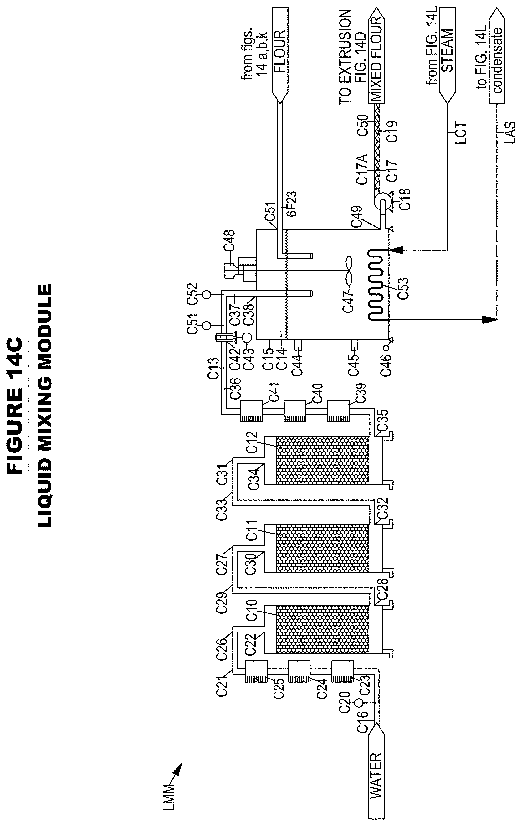
D00023
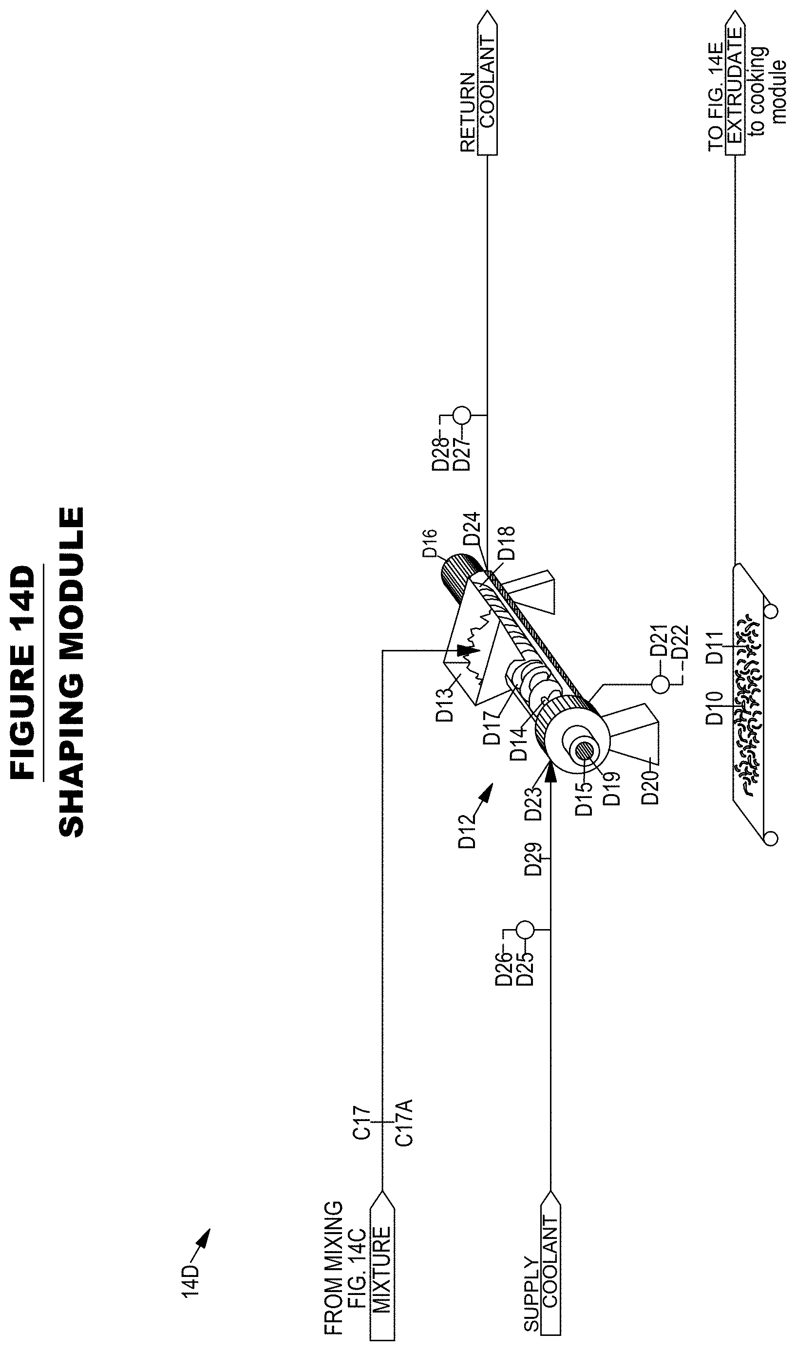
D00024
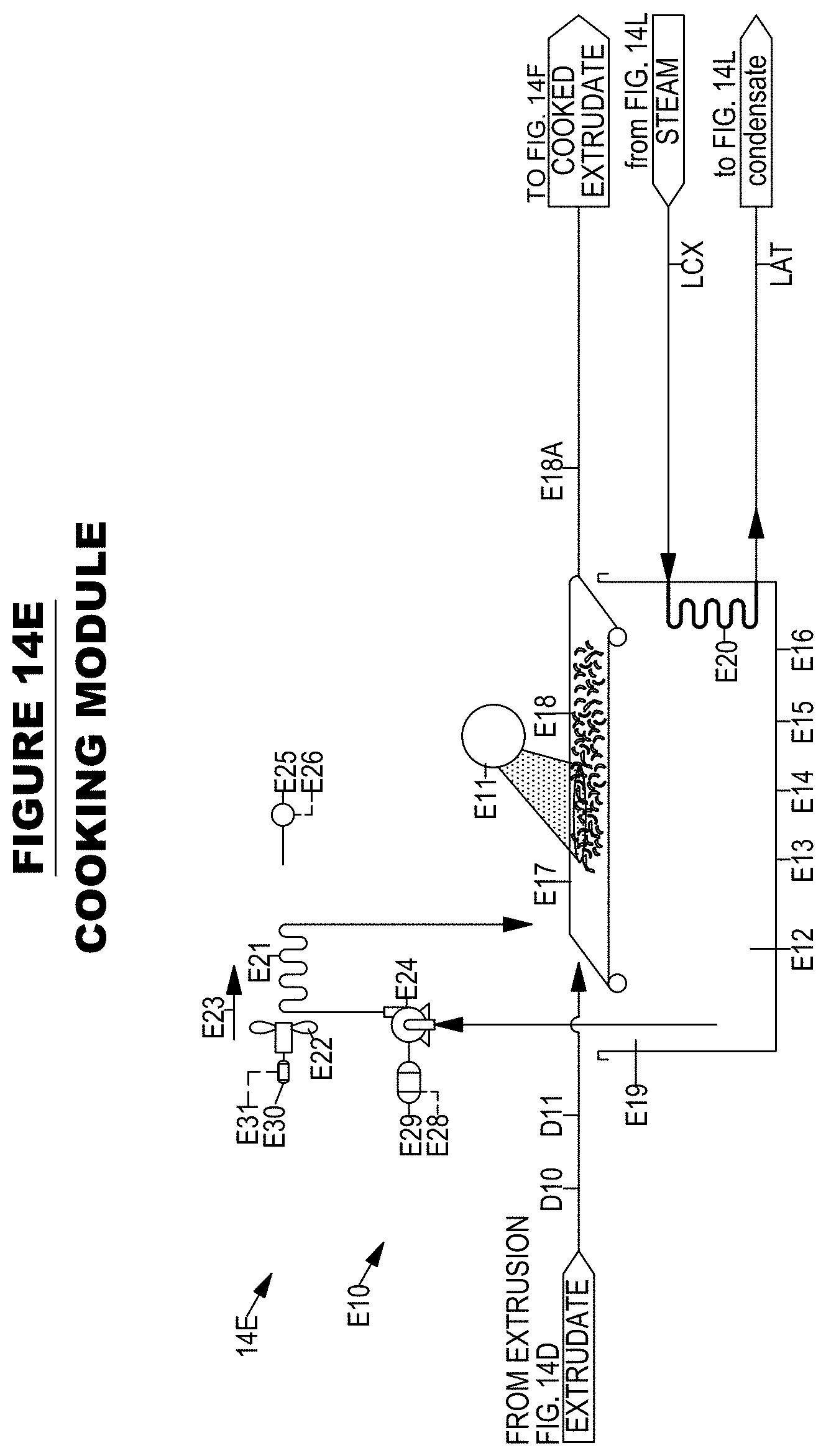
D00025

D00026

D00027

D00028

D00029

D00030

D00031
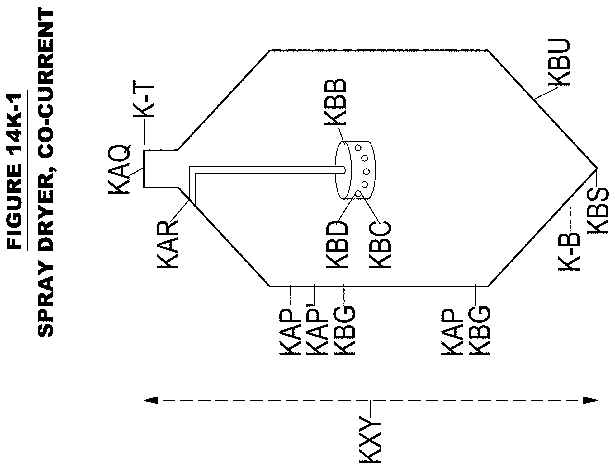
D00032

D00033
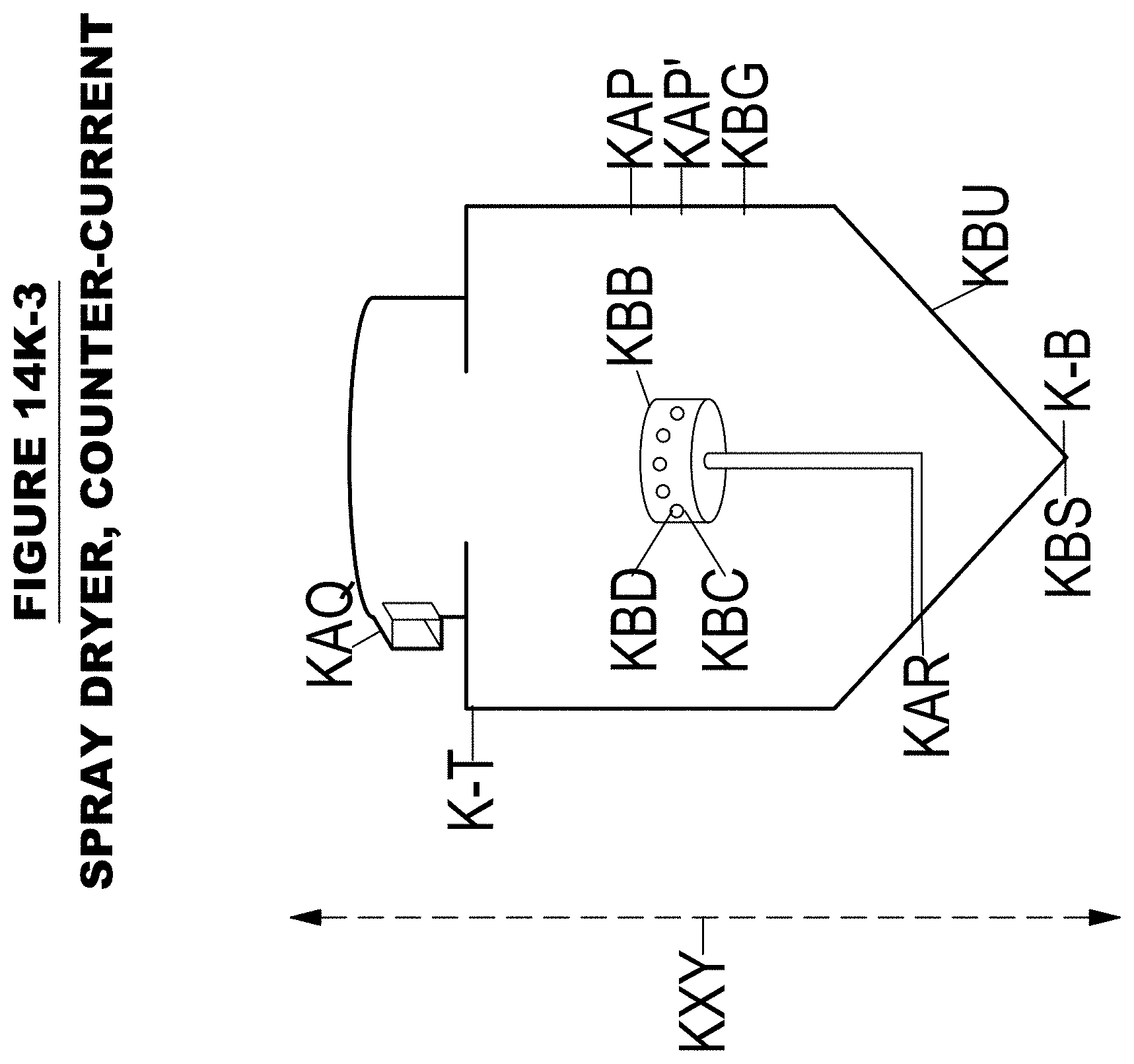
D00034
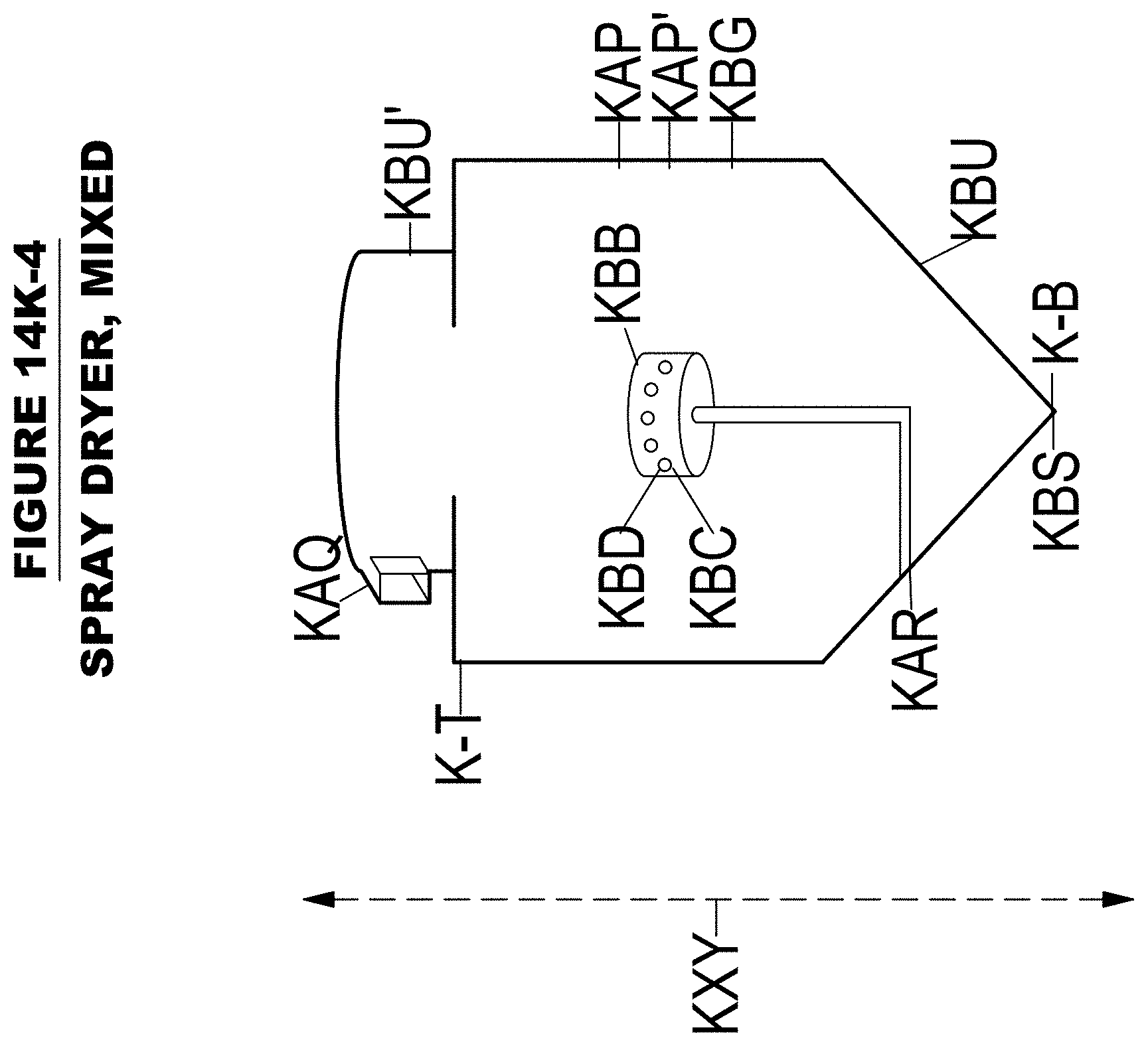
D00035

D00036

D00037

D00038

D00039

D00040

D00041

D00042

D00043

D00044

D00045
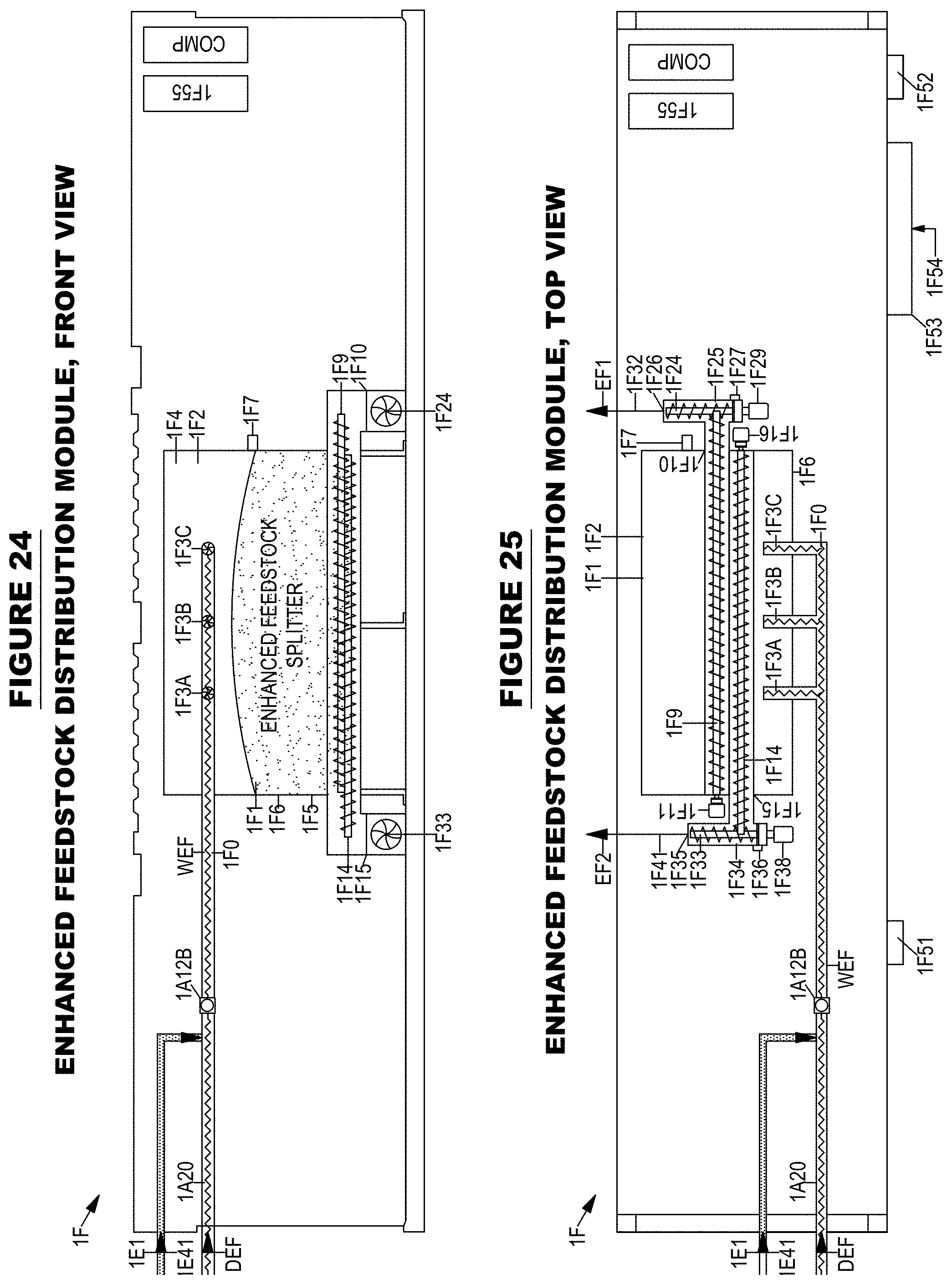
D00046

D00047

D00048

D00049

D00050

D00051

D00052

D00053

D00054

D00055

D00056

D00057

D00058
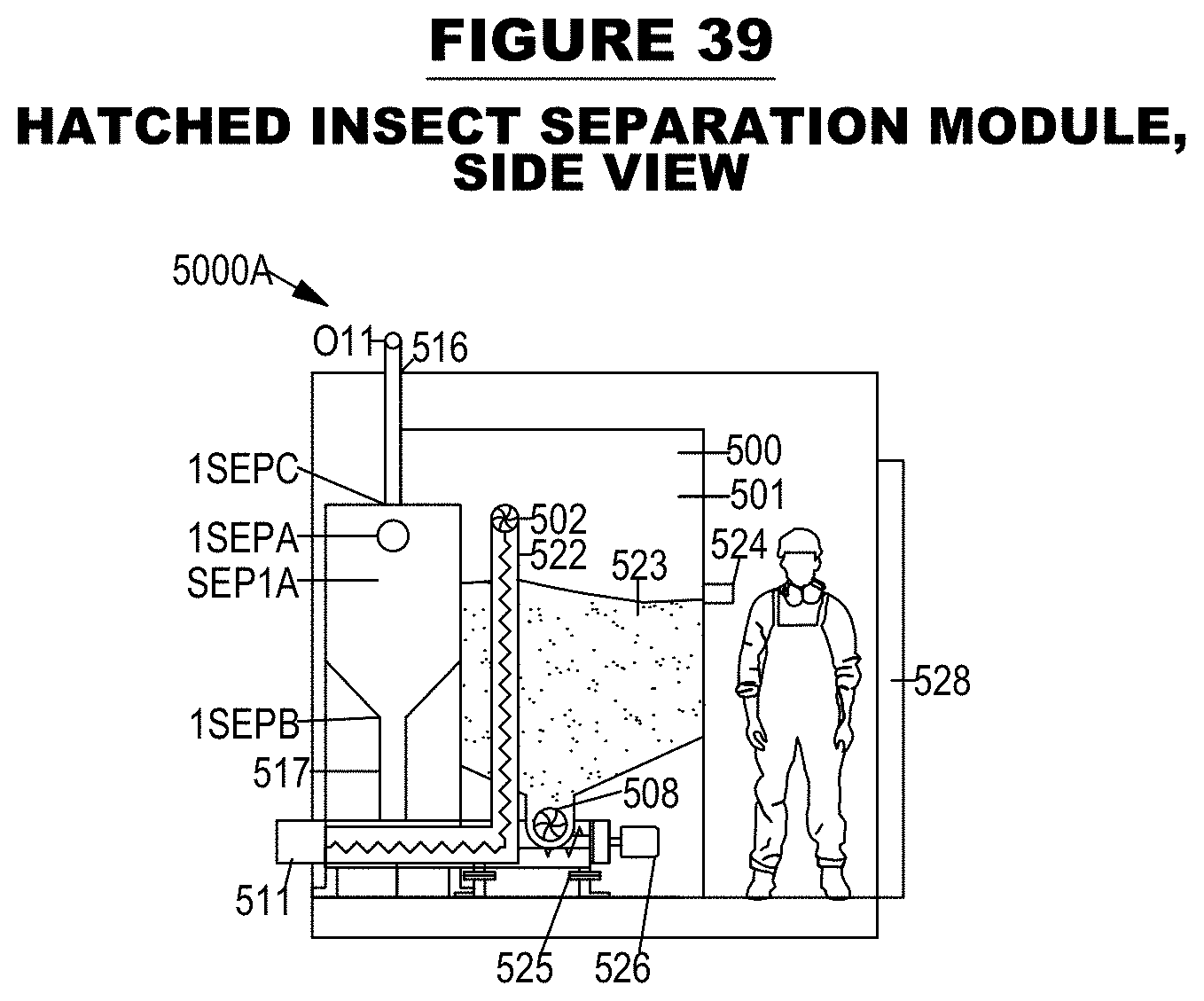
D00059

D00060

D00061

D00062

D00063

D00064
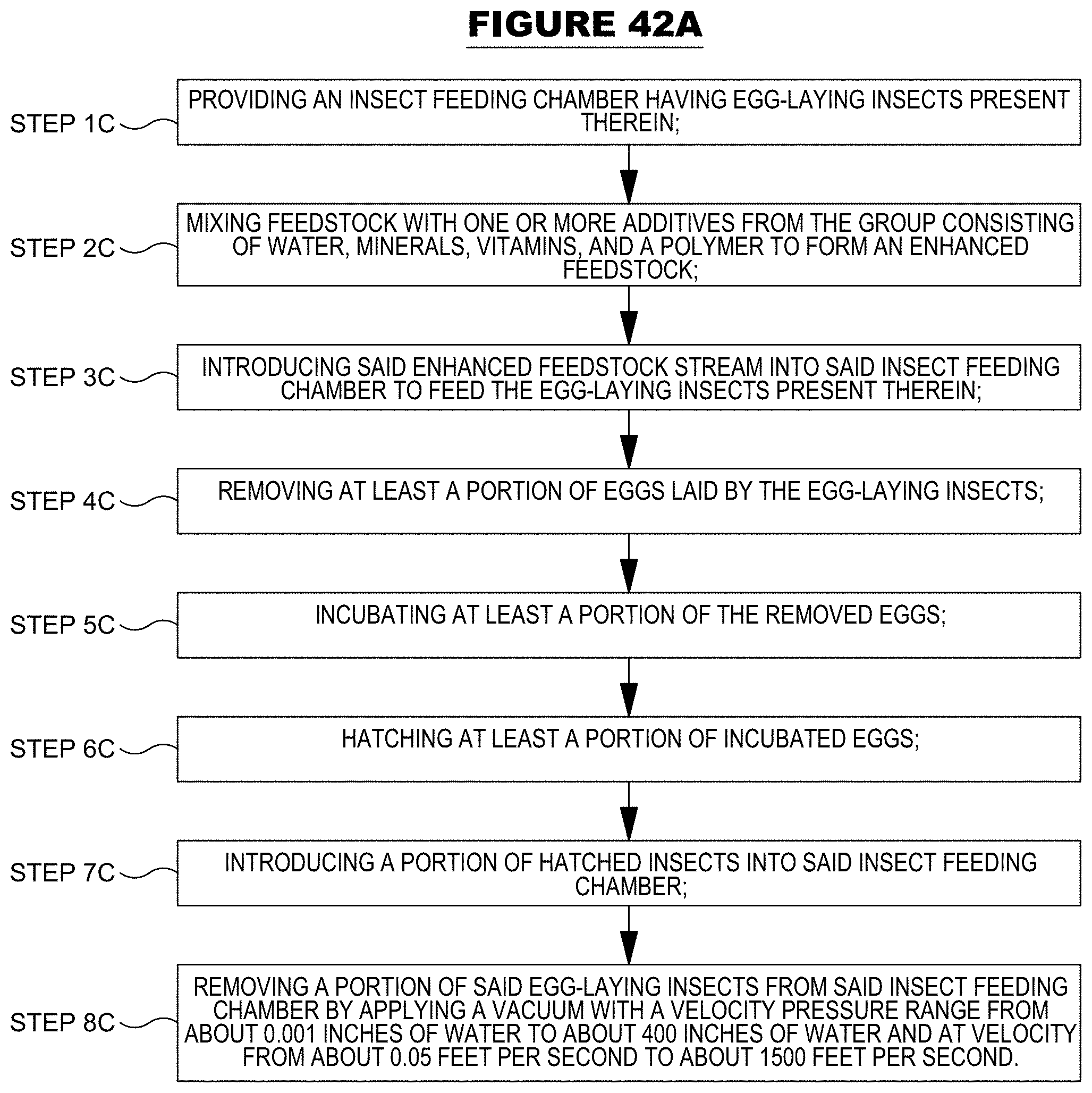
D00065

D00066

D00067

D00068

D00069
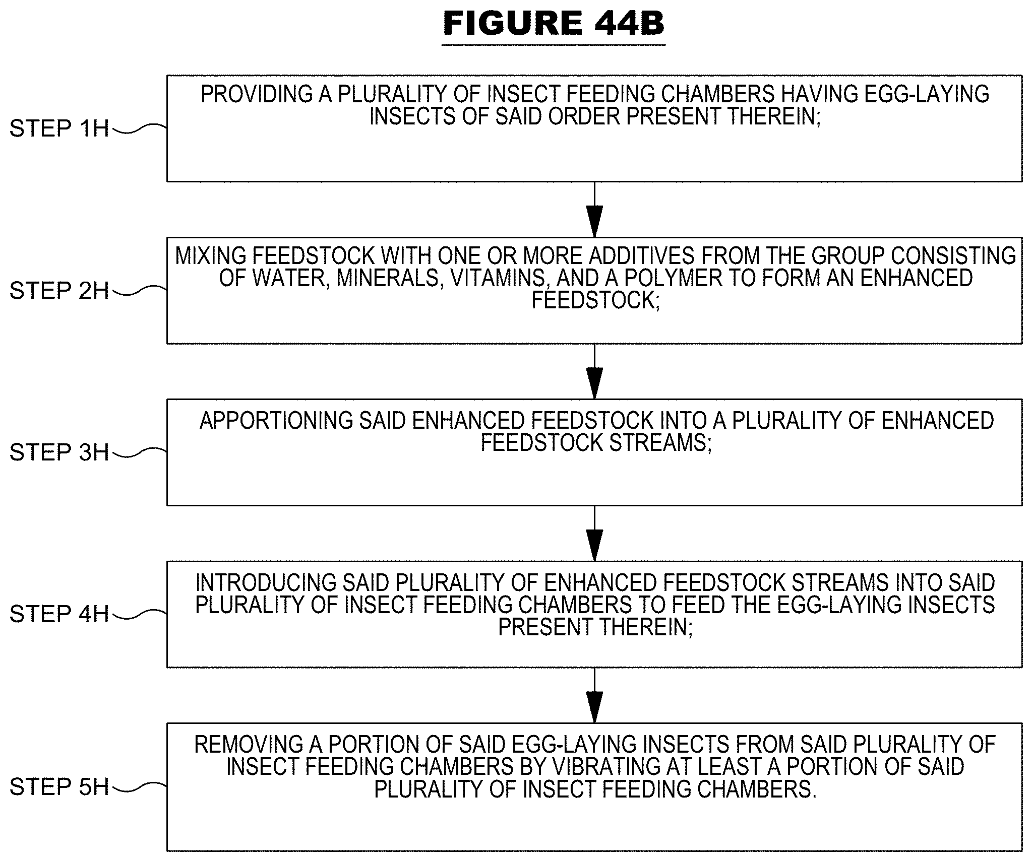
D00070

D00071

D00072
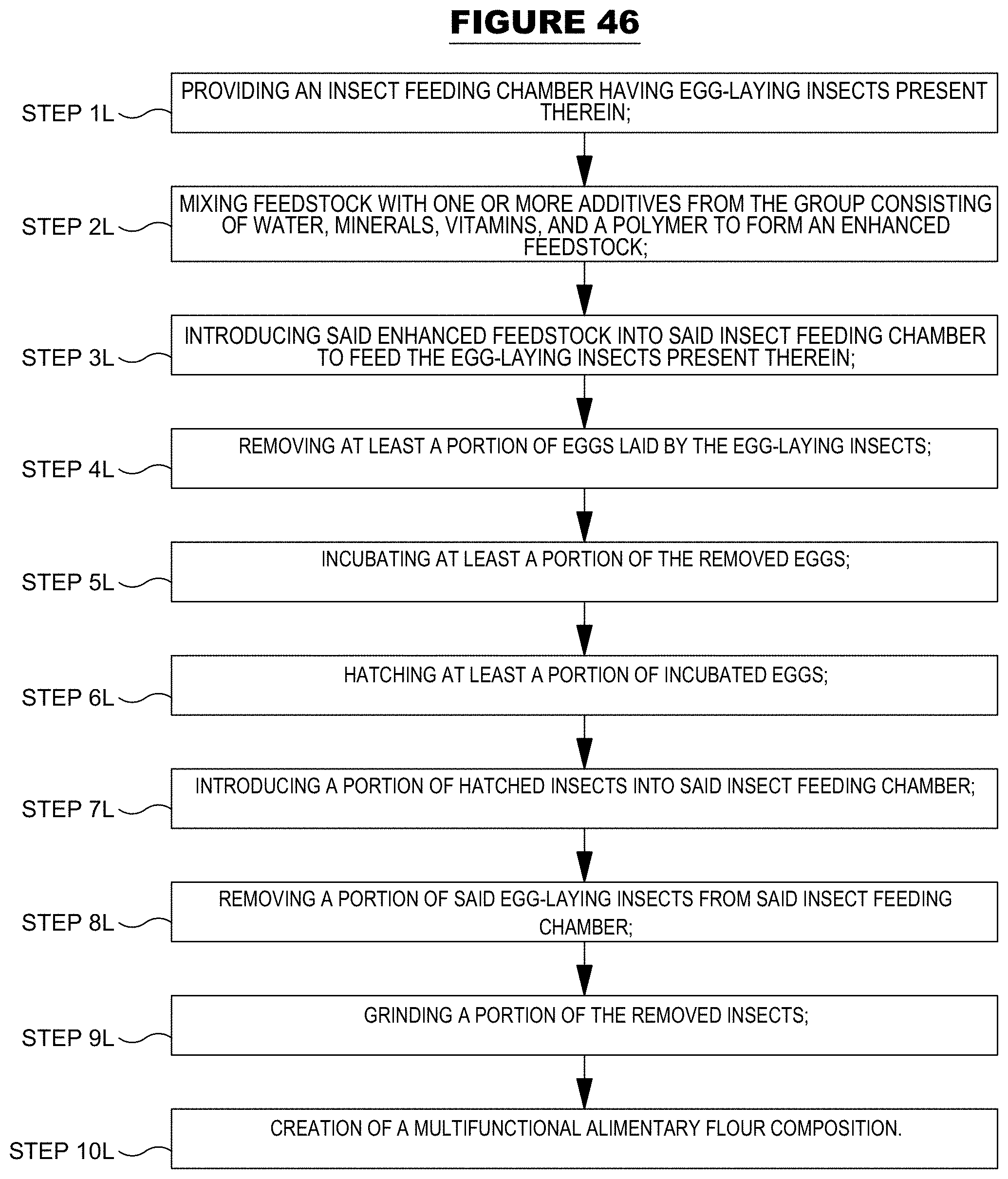
D00073

D00074

D00075

D00076

D00077
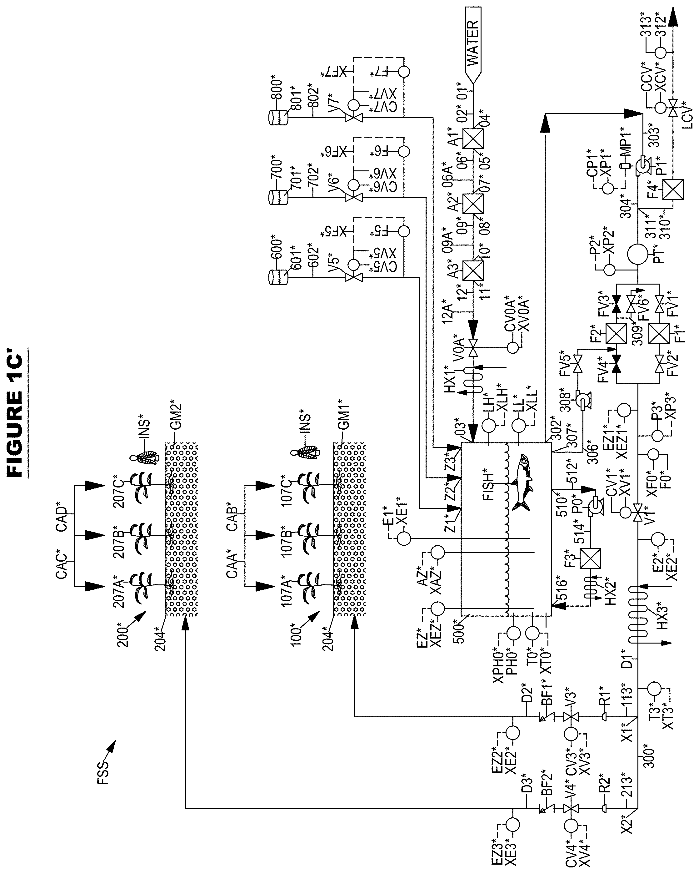
D00078

D00079
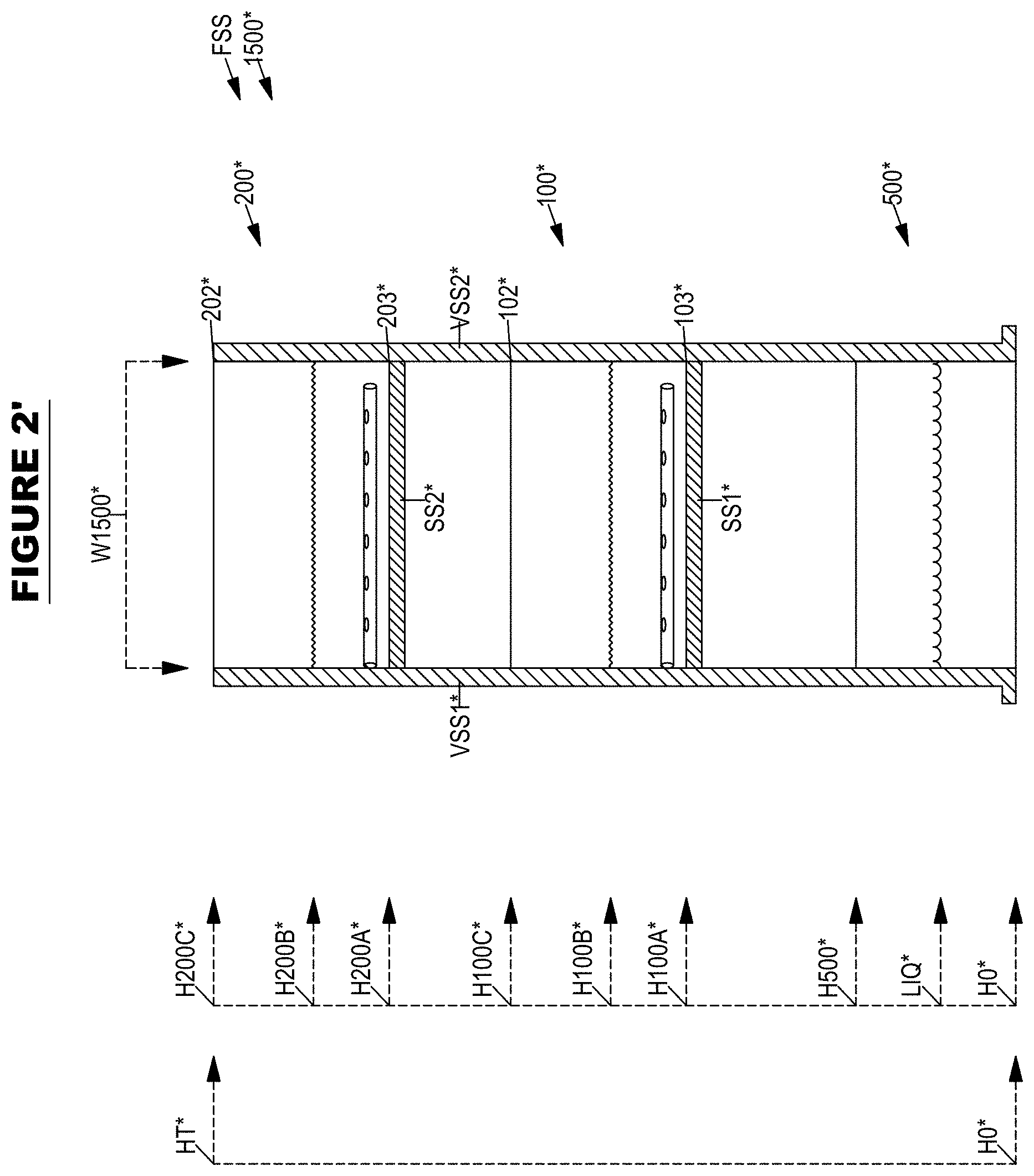
D00080
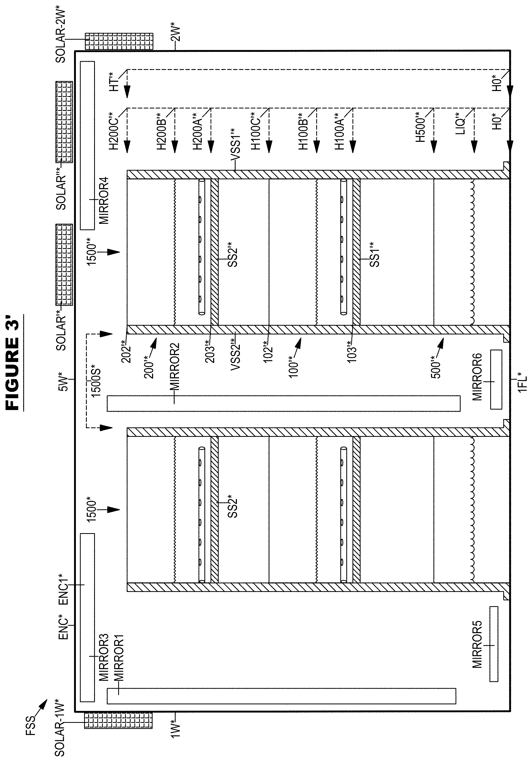
D00081

D00082

D00083

D00084

D00085

D00086
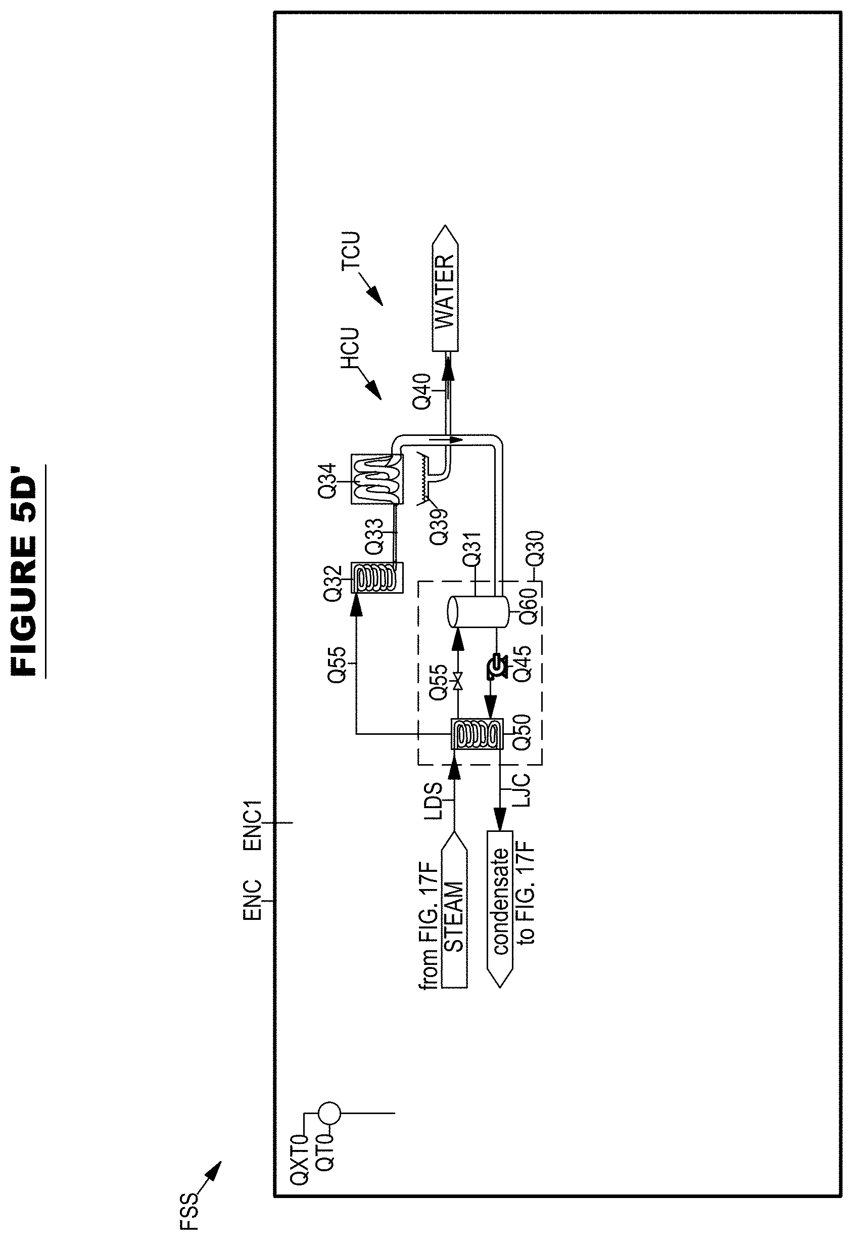
D00087

D00088

D00089

D00090

D00091

D00092

D00093

D00094
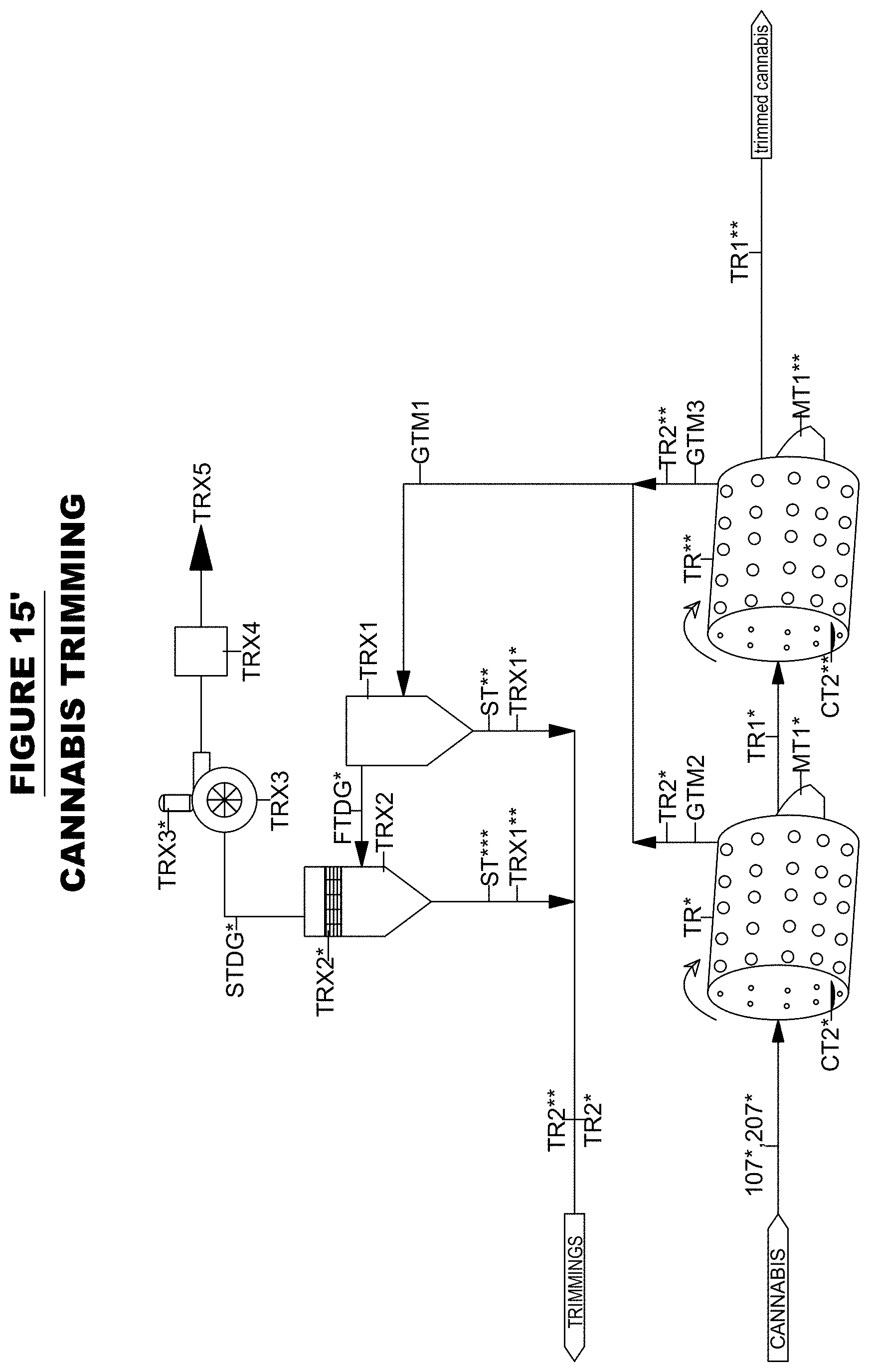
D00095

D00096

D00097

D00098

D00099

D00100

D00101
D00102
D00103

D00104

D00105

D00106

D00107

D00108

D00109
D00110

D00111

D00112

D00113

D00114
D00115
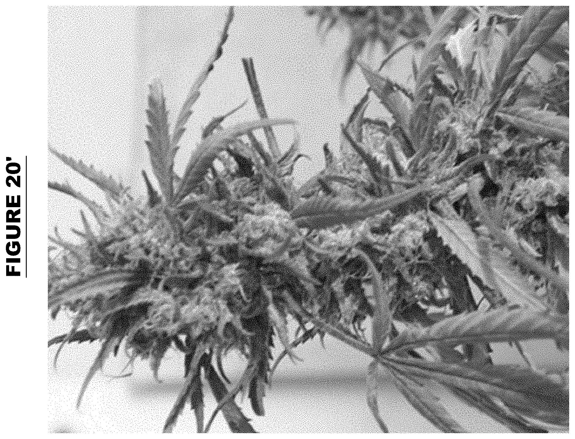
D00116

D00117

D00118

XML
uspto.report is an independent third-party trademark research tool that is not affiliated, endorsed, or sponsored by the United States Patent and Trademark Office (USPTO) or any other governmental organization. The information provided by uspto.report is based on publicly available data at the time of writing and is intended for informational purposes only.
While we strive to provide accurate and up-to-date information, we do not guarantee the accuracy, completeness, reliability, or suitability of the information displayed on this site. The use of this site is at your own risk. Any reliance you place on such information is therefore strictly at your own risk.
All official trademark data, including owner information, should be verified by visiting the official USPTO website at www.uspto.gov. This site is not intended to replace professional legal advice and should not be used as a substitute for consulting with a legal professional who is knowledgeable about trademark law.