Air Pollution Control Unit And Air Pollution Control Method, And Co2 Recovery Unit And Co2 Recovery Method
HIRATA; Takuya ; et al.
U.S. patent application number 16/635302 was filed with the patent office on 2020-11-26 for air pollution control unit and air pollution control method, and co2 recovery unit and co2 recovery method. This patent application is currently assigned to Mitsubishi Heavy Industries Engineering, Ltd.. The applicant listed for this patent is Mitsubishi Heavy Industries Engineering, Ltd.. Invention is credited to Takuya HIRATA, Masayuki INUI, Shinya KISHIMOTO, Hiroshi TANAKA.
| Application Number | 20200368682 16/635302 |
| Document ID | / |
| Family ID | 1000005036185 |
| Filed Date | 2020-11-26 |


| United States Patent Application | 20200368682 |
| Kind Code | A1 |
| HIRATA; Takuya ; et al. | November 26, 2020 |
AIR POLLUTION CONTROL UNIT AND AIR POLLUTION CONTROL METHOD, AND CO2 RECOVERY UNIT AND CO2 RECOVERY METHOD
Abstract
An air pollution control unit is configured to bring particle-containing gas and washing liquid into contact with each other to collect particles in the particle-containing gas. The air pollution control unit includes a gas washing column having a gas cleaning section in which the particle-containing gas and the washing liquid are brought into co-current contact with each other, a gas cooling column disposed downstream of the gas washing column along the gas flow and having a gas cooling section in which the particle-containing gas that has been cleaned (cleaned gas) and cooling liquid are brought into countercurrent contact with each other, and a gas communication path.
| Inventors: | HIRATA; Takuya; (Tokyo, JP) ; TANAKA; Hiroshi; (Tokyo, JP) ; INUI; Masayuki; (Tokyo, JP) ; KISHIMOTO; Shinya; (Tokyo, JP) | ||||||||||
| Applicant: |
|
||||||||||
|---|---|---|---|---|---|---|---|---|---|---|---|
| Assignee: | Mitsubishi Heavy Industries
Engineering, Ltd. Kanagawa JP |
||||||||||
| Family ID: | 1000005036185 | ||||||||||
| Appl. No.: | 16/635302 | ||||||||||
| Filed: | October 24, 2018 | ||||||||||
| PCT Filed: | October 24, 2018 | ||||||||||
| PCT NO: | PCT/JP2018/039526 | ||||||||||
| 371 Date: | January 30, 2020 |
| Current U.S. Class: | 1/1 |
| Current CPC Class: | B01D 2247/106 20130101; B01D 47/06 20130101; B01D 53/96 20130101; B01D 2247/08 20130101; B01D 53/62 20130101; B01D 53/507 20130101; B01D 53/78 20130101 |
| International Class: | B01D 53/78 20060101 B01D053/78; B01D 47/06 20060101 B01D047/06; B01D 53/50 20060101 B01D053/50; B01D 53/62 20060101 B01D053/62; B01D 53/96 20060101 B01D053/96 |
Foreign Application Data
| Date | Code | Application Number |
|---|---|---|
| Oct 31, 2017 | JP | 2017-210570 |
Claims
1. An air pollution control unit configured to bring particle-containing gas and washing liquid into contact with each other to collect particles in the particle-containing gas, the air pollution control unit comprising: a gas washing column having a gas cleaning section in which the particle-containing gas and the washing liquid are brought into co-current contact with each other, a gas cooling column which is disposed downstream of the gas washing column along a gas flow and in which the particle-containing gas that has been cleaned and cooling liquid are brought into countercurrent contact with each other, and a gas communication path through which the gas washing column and the gas cooling column are made to communicate with each other on a bottom side and through which the cleaned gas that has been cleaned in the gas washing column is introduced into the gas cooling column; wherein the gas washing column comprises: a washing liquid reservoir section which is disposed downstream of the gas cleaning section along the gas flow and in which the washing liquid is dropped and reserved; a washing liquid circulation line through which the washing liquid from the washing liquid reservoir section is circulated to a top side of the gas washing column; and a sloped plate which is disposed at a connection opening of the gas communication path on the gas washing column side and regulates the gas flow, the gas cooling column comprises: a condensed water reservoir section in which condensed water that has been condensed from the cleaned gas is reserved; a condensed water circulation line through which the condensed water from the condensed water reservoir section is circulated to a gas cooling section; a cooling device which is interposed in the condensed water circulation line and cools the condensed water; a demister which is disposed downstream of the gas cooling section along the gas flow; and a condensed water transfer line through which the condensed water from the gas cooling column is transferred to the gas washing column.
2. The air pollution control unit according to claim 1, wherein the air pollution control unit comprises, at the washing liquid reservoir section, a liquid level meter which measures the amount of the washing liquid reserved.
3. The air pollution control unit according to claim 1, wherein the particle-containing gas contains sulfur oxide, and the air pollution control unit comprises a basic compound supply section which supplies a basic compound into the washing liquid.
4. A CO.sub.2 recovery unit comprising: the air pollution control unit according to claim 3, a gas exhausting line through which treated gas discharged from the gas cooling column is exhausted, a CO.sub.2 absorber in which the cooled gas is introduced through the gas exhausting line, and CO.sub.2 in the cooled gas and CO.sub.2 absorbent are brought into contact with each other, and thereby CO.sub.2 is removed, a CO.sub.2 absorbent regenerator in which a rich solution that has absorbed CO.sub.2 is regenerated with steam from a reboiler, a rich solution supply line through which the rich solution is drawn from the CO2 absorber and is introduced to the CO.sub.2 absorbent regenerator, and a lean solution supply line through which a lean solution that has released CO.sub.2 and has been regenerated in the CO.sub.2 absorbent regenerator is drawn from the CO.sub.2 absorbent regenerator and is introduced into the CO.sub.2 absorber to be reused as the CO.sub.2 absorbent.
5. An air pollution control method configured to bring particle-containing gas and washing liquid into contact with each other and thereby to collect particles in the particle-containing gas, the air pollution control method comprising: a dedusting step in which the particle-containing gas and the washing liquid are brought into co-current contact with each other in a gas washing column, and gas after gas cleaning flows down and collides with a fluid surface in a washing liquid reservoir section through a gas flow channel which is narrowed by a gas flow regulating plate, and thereby the gas is dedusted; a cooling step in which the cleaned gas resulting from the dedusting is cooled in a gas cooling column, and at the same time water in the cleaned gas is condensed with cooling water and thereby condensed water is obtained; and a washing liquid replenishing step in which the condensed water obtained is supplied to the gas washing column to replenish the washing liquid.
6. The air pollution control method according to claim 5, wherein the pressure loss in the gas washing column is controlled by controlling the liquid level in the washing liquid reservoir section.
7. The air pollution control method according to claim 5, wherein the particle-containing gas contains sulfur oxide, and a basic compound is supplied into the washing liquid to perform desulfurization.
8. A CO.sub.2 recovery method comprising: a cleaning and desulfurization step in which particle-containing gas containing sulfur oxide and CO.sub.2 is introduced into a gas washing column, a basic compound is supplied into washing liquid that is being circulated, and the particle-containing gas is dedusted and desulfurized; a cooling step in which the cleaned gas resulting from the dedusting and desulfurization is cooled in a gas cooling column, and at the same time water in the cleaned gas is condensed with cooling water and thereby condensed water is obtained; a washing liquid replenishing step in which the condensed water obtained is supplied to the gas washing column to replenish the washing liquid; a CO.sub.2 absorbing step in which treated gas resulting from the gas cooling is introduced into a CO.sub.2 absorber, and CO.sub.2 in the cooled gas and CO.sub.2 absorbent are brought into contact with each other, and thereby CO.sub.2 is removed; a CO.sub.2 absorbent regeneration step in which a rich solution that has absorbed CO.sub.2 is introduced into a CO.sub.2 absorbent regenerator and is regenerated with reboiler steam; and a step in which the CO.sub.2 absorbent is circulated for reuse between the CO.sub.2 absorber and the CO.sub.2 absorbent regenerator through circulation lines.
Description
FIELD
[0001] The present invention relates to an air pollution control unit and an air pollution control method, and a CO.sub.2 recovery unit and a CO.sub.2 recovery method each for removing particles from a gas.
BACKGROUND
[0002] The greenhouse effect of CO.sub.2 has been pointed out as one of the causes of global warming phenomena, and countermeasures thereto have recently become urgent worldwide to protect the global environment. CO.sub.2 is generated from all kinds of human activity fields where fossil fuels are combusted, and there tend to be stronger calls for the regulation of carbon dioxide emissions. Such demands are directed to power generating facilities such as thermal power plants which use large amounts of fossil fuels, and have led to intense studies on methods in which flue gas exhausted from industrial facilities such as boilers and gas turbines are brought into contact with amine-based CO.sub.2 absorbent, and thereby CO.sub.2 is removed and recovered from the flue gas, and on air pollution control systems which store the recovered CO.sub.2 without releasing it to the atmosphere.
[0003] Numerous CO.sub.2 recovery units have been proposed which perform steps for removing and recovering CO.sub.2 from a flue gas using CO.sub.2 absorbent described above. Such steps include a step of bringing the flue gas and the CO.sub.2 absorbent into contact with each other in a CO.sub.2 absorber (hereinafter also simply referred to "absorber"), and a step of heating the CO.sub.2 absorbent which has absorbed CO.sub.2 in an absorbent regenerator (hereinafter also simply referred to as "regenerator") to release CO.sub.2 and to regenerate the CO.sub.2 absorbent, and circulating the CO.sub.2 absorbent back to the CO.sub.2 absorber for reuse.
[0004] In the absorber, the flue gas is brought into countercurrent contact with the CO.sub.2 absorbent, for example, one including an absorption component such as alkanolamine, and CO.sub.2 in the flue gas is absorbed into the CO.sub.2 absorbent by chemical reaction (exothermic reaction) and the flue gas from which CO.sub.2 is removed is released out of the system. The CO.sub.2 absorbent which has absorbed CO.sub.2 is also called a rich solution. The rich solution is pressurized with a pump, heated in a heat exchanger using the hot CO.sub.2 absorbent (lean solution) regenerated by releasing CO.sub.2 in the regenerator, and supplied to the regenerator.
[0005] Incidentally, because flue gas contains particles, an air pollution control unit is installed which performs pretreatments such as gas cleaning and gas cooling on the particle-containing gas before the CO.sub.2 removal and recovery steps. An air pollution control unit of this type that has been proposed adopts a system in which a gas is treated by countercurrent gas-liquid contact in a packed section of a gas washing column (see, for example, Patent Literature 1). In another gas treating system that has been proposed, a gas is treated by co-current gas-liquid contact followed by countercurrent gas-liquid contact (see, for example, Patent Literature 2).
CITATION LIST
Patent Literature
[0006] Patent Literature 1: Japanese Patent Application Laid-open No. 2005-87828 A
[0007] Patent Literature 2: Japanese Patent Application Laid-open No. S59-160519 A
SUMMARY
Technical Problem
[0008] Unfortunately, the countercurrent gas-liquid contact system disclosed in Patent Literature 1 has a drawback in that the performance in collecting particles from a gas is not sufficiently enhanced. Furthermore, the system disclosed in Patent Literature 2 which involves co-current gas-liquid contact followed by countercurrent gas-liquid contact has a problem in that the co-current gas-liquid contact section receives a large supply of makeup water. Furthermore, if the particle collection efficiency at the gas washing column is low, for example, particles which are collected into a liquid downstream of the gas washing column become attached to the apparatus to cause fouling and clogging problems, and the particle-containing liquid scatters to the gas to cause adverse effects downstream of the air pollution control unit.
[0009] In light of the problems discussed above, an object of the present invention is to provide an air pollution control unit, an air pollution control method, a CO.sub.2 recovery unit and a CO.sub.2 recovery method which each allow particle-containing gas to be cleaned in a gas washing column with an enhanced particle collection performance.
Solution to Problem
[0010] To solve the above problem, a first invention according to the present invention is an air pollution control unit configured to bring particle-containing gas and washing liquid into contact with each other to collect particles in the particle-containing gas. The air pollution control unit includes a gas washing column having a gas cleaning section in which the particle-containing gas and the washing liquid are brought into co-current contact with each other, a gas cooling column which is disposed downstream of the gas washing column along a gas flow and in which the particle-containing gas that has been cleaned and cooling liquid are brought into countercurrent contact with each other, and a gas communication path through which the gas washing column and the gas cooling column are made to communicate with each other on a bottom side and through which the cleaned gas that has been cleaned in the gas washing column is introduced into the gas cooling column. The gas washing column includes a washing liquid reservoir section which is disposed downstream of the gas cleaning section along the gas flow and in which the washing liquid is dropped and reserved, a washing liquid circulation line through which the washing liquid from the washing liquid reservoir section is circulated to a top side of the gas washing column, and a sloped plate which is disposed at a connection opening of the gas communication path on the gas washing column side and regulates the gas flow. The gas cooling column includes a condensed water reservoir section in which condensed water that has been condensed from the cleaned gas is reserved, a condensed water circulation line through which the condensed water from the condensed water reservoir section is circulated to a gas cooling section, a cooling device which is interposed in the condensed water circulation line and cools the condensed water, a demister which is disposed downstream of the gas cooling section along the gas flow, and a condensed water transfer line through which the condensed water from the gas cooling column is transferred to the gas washing column.
[0011] A second invention is the air pollution control unit according to the first invention, in which the air pollution control unit comprises, at the washing liquid reservoir section, a liquid level meter which measures the amount of the washing liquid reserved.
[0012] A third invention is the air pollution control unit according to the first or second invention, in which the particle-containing gas contains sulfur oxide, and the air pollution control unit comprises a basic compound supply section which supplies a basic compound into the washing liquid.
[0013] A fourth invention is a CO.sub.2 recovery unit including the air pollution control unit according to third invention, a gas exhausting line through which treated gas discharged from the gas cooling column is exhausted, a CO.sub.2 absorber in which the cooled gas is introduced through the gas exhausting line, and CO.sub.2 in cooled gas and CO.sub.2 absorbent are brought into contact with each other, and thereby CO.sub.2 is removed, a CO.sub.2 absorbent regenerator in which a rich solution that has absorbed CO.sub.2 is regenerated with steam from a reboiler, a rich solution supply line through which the rich solution is drawn from the CO.sub.2 absorber and is introduced to the CO.sub.2 absorbent regenerator, and a lean solution supply line through which a lean solution that has released CO.sub.2 and has been regenerated in the CO.sub.2 absorbent regenerator is drawn from the CO.sub.2 absorbent regenerator and is introduced into the CO.sub.2 absorber to be reused as the CO.sub.2 absorbent.
[0014] A fifth invention is an air pollution control method configured to bring particle-containing gas and washing liquid into contact with each other and thereby to collect particles in the particle-containing gas. The air pollution control method includes a deducting step in which the particle-containing gas and the washing liquid are brought into co-current contact with each other in a gas washing column, and gas after gas cleaning flows down and collides with a fluid surface in a washing liquid reservoir section through a gas flow channel which is narrowed by a gas flow regulating plate, and thereby the gas is dedusted, a cooling step in which the cleaned gas resulting from the dedusting is cooled in a gas cooling column, and at the same time water in the cleaned gas is condensed with cooling water and thereby condensed water is obtained, and a washing liquid replenishing step in which the condensed water obtained is supplied to the gas washing column to replenish the washing liquid.
[0015] A sixth invention is the air pollution control method according to the fifth invention, in which the pressure loss in the gas washing column is controlled by controlling the liquid level in the washing liquid reservoir section.
[0016] A seventh invention is the air pollution control method according to the fifth or sixth invention, in which the particle-containing gas contains sulfur oxide, and a basic compound is supplied into the washing liquid to perform desulfurization.
[0017] An eighth invention is a CO.sub.2 recovery method including a cleaning and desulfurization step in which particle-containing gas containing sulfur oxide and CO.sub.2 is introduced into a gas washing column, a basic compound is supplied into washing liquid that is being circulated, and the particle-containing gas is dedusted and desulfurized, a cooling step in which the cleaned gas resulting from the dedusting and desulfurization is cooled in a gas cooling column, and at the same time water in the cleaned gas is condensed with cooling water and thereby condensed water is obtained, a washing liquid replenishing step in which the condensed water obtained is supplied to the gas washing column to replenish the washing liquid, a CO.sub.2 absorbing step in which treated gas resulting from the gas cooling is introduced into a CO.sub.2 absorber, and CO.sub.2 in the cooled gas and CO.sub.2 absorbent are brought into contact with each other, and thereby CO.sub.2 is removed, a CO.sub.2 absorbent regeneration step in which a rich solution that has absorbed CO.sub.2 is introduced into a CO.sub.2 absorbent regenerator and is regenerated with reboiler steam, and a step in which the CO.sub.2 absorbent is circulated for reuse between the CO.sub.2 absorber and the CO.sub.2 absorbent regenerator through circulation lines.
Advantageous Effects of Invention
[0018] According to the present invention, a gas washing column and a gas cooling column are made to communicate with each other through a gas communication path provided with a sloped plate. The sloped plate is disposed at a connection opening on the gas washing column side to regulate the flow of gas, so that efficiency of collision of cleaned gas and a fluid bath at the time of entry of the cleaned gas into the communication path can be increased. Furthermore, a condensed water transfer line is provided through which condensed water recovered at the gas cooling column is transferred to the gas washing column, and the condensed water from the gas cooling column is introduced into the gas washing column, thereby making it possible to eliminate the need to supply makeup water to the gas washing column or to reduce the amount of makeup water that is required.
BRIEF DESCRIPTION OF DRAWINGS
[0019] FIG. 1 is a schematic view of an air pollution control unit according to a first embodiment.
[0020] FIG. 2A is a detailed schematic view of a gas washing column according to conventional art.
[0021] FIG. 2B is a detailed schematic view of a gas washing column according to the first embodiment.
[0022] FIG. 3 is a schematic view of an air pollution control unit according to a second embodiment.
[0023] FIG. 4 is a schematic view of an air pollution control unit according to a third embodiment.
[0024] FIG. 5 is a schematic view of a CO.sub.2 recovery unit including an air pollution control unit according to a fourth embodiment.
DESCRIPTION OF EMBODIMENTS
[0025] Preferred embodiments of the present invention will be described in detail with reference to the accompanying drawings. The scope of the present invention is not limited by these embodiments and, where a plurality of embodiments are presented, includes combinations of such embodiments.
First Embodiment
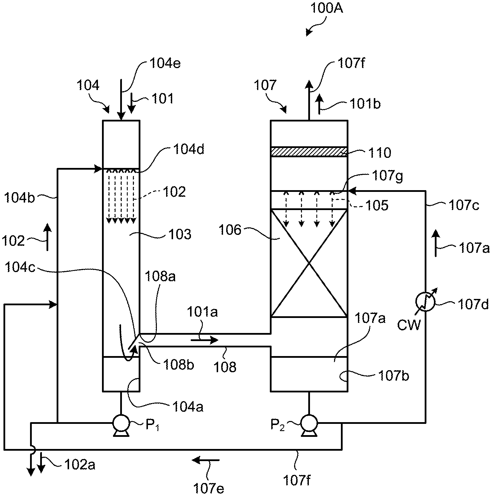
[0026] FIG. 1 is a schematic view of an air pollution control unit according to a first embodiment.
[0027] As illustrated in FIG. 1, the air pollution control unit 100A according to the first embodiment is an air pollution control unit configured to bring particle-containing gas 101 and washing liquid 102 into contact with each other to collect particles in the particle-containing gas 101, and the air pollution control unit 100A includes: a gas washing column 104 having a gas cleaning section 103 in which the particle-containing gas 101 and the washing liquid 102 are brought into co-current contact with each other; a gas cooling column 107 disposed downstream of the gas washing column 104 along the gas flow and having a gas cooling section 106 in which the particle-containing gas 101a that has been cleaned (cleaned gas) and cooling liquid 105 are brought into countercurrent contact with each other; and a gas communication path 108 through which the gas washing column 104 and the gas cooling column 107 are made to communicate with each other on a bottom side and through which the cleaned gas 101a that has been cleaned in the gas washing column 104 is introduced into the gas cooling column 107.
[0028] The gas washing column 104 has a top portion from which the particle-containing gas 101 is introduced thereinto through a gas introduction line 104e, so as to make gas flows having a high flow velocities toward the bottom portion of the gas washing column 104.
[0029] Furthermore, the gas washing column 104 has: a washing liquid reservoir section 104a which is disposed downstream of the gas cleaning section 103 along the gas flow and in which the washing liquid 102 is dropped and reserved; a washing liquid circulation line 104b through which the washing liquid 102 from the washing liquid reservoir section 104a is circulated to a top side of the gas washing column 104; and a sloped plate 104c which is disposed at a connection opening 108a of the gas communication path 108 on the gas washing column 104 side and regulates the gas flow.
[0030] On the distal end side of the washing liquid circulation line 104b, a nozzle 104d for spraying the washing liquid 102 that is being circulated is disposed and drops the washing liquid 102 toward the washing liquid reservoir section 104a. The washing liquid circulation line 104b is provided with a fluid circulating pump P.sub.1 which draws the washing liquid 102 from the washing liquid reservoir section 104a and circulates the washing liquid 102 to the nozzle 104d. The excess of the washing liquid 102 is discharged outside as excess fluid 102a.
[0031] The particle-containing gas 101 introduced is brought into co-current gas-liquid contact with the washing liquid 102, and thereby particles are removed, and thus the flow velocity of the gas flowing down in the column can be higher than a countercurrent gas-liquid contact system. It is Preferable that the gas flow velocity be, for example, about 10 to 20 m/s.
[0032] As a result, the particle-containing gas 101 has a relatively high flow velocity (for example, gas flow velocity of about 10 m/s to 20 m/s), and thereby the gas is allowed to collide intensively with the vicinity of the surface of the fluid bath in the washing liquid reservoir section 104a. Thus, enhancements are attained in the performance in collecting the particles in the particle-containing gas 101 into the pool of the washing liquid 102.
[0033] At the connection opening 108a of the gas communication path 108 on the gas washing column 104 side, the sloped plate 104c is disposed on the upper end side of the connection opening 108a and inclines at a predetermined angle to form an open path 108b. The sloped plate 104c is disposed to extend from an inner corner portion of the sidewall of the gas washing column 104 to form the open path 108b, and thus regulates the gas flow of the cleaned gas 101a passing by the inner corner portion of the sidewall of the gas washing column 104.
[0034] FIG. 2A is a detailed schematic view of a gas washing column according to the conventional art. FIG. 2B is a detailed schematic view of the gas washing column according to the first embodiment. In the conventional art illustrated in FIG. 2A, no sloped plate is provided at a connection opening 108a of a gas communication path 108 on the gas washing column 104 side. In this case, cleaned gas 101a simply passes by the inner corner portion without being regulated, and thus has less chances of collision with a washing liquid reservoir section 104a. Consequently, most of the particles flow directly into the gas communication path 108 without being removed by the pool of the washing liquid 102.
[0035] In contrast, as illustrated in FIG. 2B, when the sloped plate 104c is provided at the connection opening 108a of the gas communication path 108 on the gas washing column side, the cleaned gas 101a passing by the inner corner portion first collides with the upper surface of the sloped plate 104c and is guided to the fluid surface in the washing liquid reservoir section 104a to collide intensively with the fluid surface. Thus, enhancements are attained in the performance in collecting the particles in the particle-containing gas 101 into the fluid bath.
[0036] Furthermore, the installation of the sloped plate 104c narrows the flow channel (D1>D2) passing through the lower portion of the gas washing column 104, and thereby the cleaned gas 101a gains a further increase in gas flow velocity, so that collision efficiency of the cleaned gas 101a and the fluid surface in the washing liquid reservoir section 104a can be increased.
[0037] As discussed above, the installation of the sloped plate 104c allows the cleaned gas 101a to be introduced to the gas cooling column 107 so that the cleaned gas 101a collides directly with the fluid surface in the washing liquid reservoir section 104a, thus making it possible to increase the particle removal efficiency at the fluid surface.
[0038] Here, the pressure loss in the gas washing column 104 which removes the particle-containing gas 101 is preferably in the range of 1,000 to 3,000 Pa.
[0039] Furthermore, in the gas washing column 104, a throat portion narrowing the gas flow channel may be formed above a part where the sloped plate 104c is disposed, thereby further increasing the flow velocity of the cleaned gas 101a and efficiency of collision of the cleaned gas 101a and the fluid surface in the washing liquid reservoir section 104a.
[0040] Furthermore, the gas cooling column 107 has: a condensed water reservoir section 107b in which condensed water 107a that has been condensed from the cleaned gas 101a is reserved; a condensed water circulation line 107c through which the condensed water 107a from the condensed water reservoir section 107b is circulated as the cooling liquid 105 to the gas cooling section 106; a cooling device 107d which is interposed in the condensed water circulation line 107c and cools the condensed water 107a; a demister 110 which is disposed downstream of the gas cooling section 106 along the gas flow; and a condensed water transfer line 107f through which a condensed water discharge 107e from the gas cooling column 107 is transferred to the gas washing column 104.
[0041] The gas cooling column 107 is configured to cool the cleaned gas 101a with cooling water CW that is circulated, and the cooling liquid 105 is obtained with the cooling device 107d interposed in the condensed water circulation line 107c through which the condensed water 107a from the cleaned gas 101a is circulated.
[0042] The condensed water circulation line 107c is provided with a nozzle 107g which sprays the cooling liquid 105 being circulated and drops the cooling liquid 105 toward the condensed water reservoir section 107b, and thereby the water contained in the cleaned gas 101a is condensed. The condensed water circulation line 107c is provided with a fluid circulating pump P.sub.2 which circulates the cooling liquid 105.
[0043] Furthermore, the gas cooling column 107 has a condensed water transfer line 107f through which the condensed water 107a formed in the column is transferred to the gas washing column 104.
[0044] As discussed above, the gas cooling column 107 is configured to recover water contained in the cleaned gas 101a as the condensed water 107a in the column, and to transfer the condensed water 107a that has been recovered, as the condensed water discharge 107e to the gas washing column 104 through the condensed water transfer line 107f. Thus, the condensed water discharge 107e can be introduced as makeup water for the washing liquid used in the gas washing column. As a result, it becomes possible to eliminate the need to supply makeup water to the gas washing column 104 or to reduce the amount of makeup water that is required.
[0045] Furthermore, it is preferable that the demister 110 disposed in the gas cooling column 107 to collect microparticles remaining in the gas have a pressure loss in the range of 500 to 2,500 Pa. Furthermore, the demister 110 may include a glass fiber layer.
[0046] An air pollution control method according to the present first embodiment is an air pollution control method configured to bring particle-containing gas 101 and washing liquid 102 into contact with each other and thereby to collect particles in the particle-containing gas 101, and the air pollution control method includes: a dedusting step in which the particle-containing gas 101 and the washing liquid 102 are brought into co-current contact with each other in the gas washing column 104, and the cleaned gas 101a flows down and collides with the fluid surface in the washing liquid reservoir section 104a through a gas flow channel which is narrowed by the sloped plate 104c that is a gas flow regulating plate, and thereby the gas is dedusted; a cooling step in which the cleaned gas 101a having been dedusted is cooled in the gas cooling column 107, and at the same time water in the cleaned gas 101a is condensed with the cooling liquid 105 and thereby condensed water 107a is obtained; and a washing liquid replenishing step in which the condensed water 107a obtained is supplied as a condensed water discharge 107e to the gas washing column 104 to replenish the washing liquid 102.
[0047] With this air pollution control method, the gas washing column 104 and the gas cooling column 107 communicate with each other through the gas communication path 108, and the sloped plate 104c which regulates the flow of gas is provided at the connection opening 108a of the gas communication path 108 on the gas washing column 104 side, so that efficiency of collision of the cleaned gas 101a and the fluid bath at the time of entry of the cleaned gas 101a into the gas communication path 108 can be increased. Furthermore, the condensed water 107a recovered in the gas cooling column 107 is transferred as the condensed water discharge 107e to the gas washing column 104. Thus, the method makes it possible to eliminate the need to supply makeup water to the gas washing column 104 or to reduce the amount of makeup water that is required.
Second Embodiment
[0048] FIG. 3 is a schematic view of an air pollution control unit according to a second embodiment. The same reference numerals will be used for the same features as in the first embodiment, and overlaps will be omitted in the description of such features. As illustrated in FIG. 3, the air pollution control unit 100E according to the second embodiment includes: a liquid level meter 120 which controls the liquid level in the washing liquid reservoir section 104a; a first pressure meter 121A which measures the pressure at an introduction section of the gas washing column 104; and a second pressure meter 121B which measures the pressure in the gas communication path 108.
[0049] In the gas washing column 104, the liquid level meter 120 is disposed to respond to any change in the gas flow velocity of the particle-containing gas 101 that is being introduced into the gas washing column 104. When a change in the gas volume of the particle-containing gas 101 introduced is detected by the measurement with the first pressure meter 121A and the second pressure meter 121B, the liquid level meter 120 controls the liquid level in the washing liquid reservoir section 104a to control the pressure loss in the gas washing column 104.
[0050] Specifically, when the pressure loss decreases, the liquid level meter 120 is controlled to raise the liquid level of the liquid level meter 120, thus increasing the flow velocity of the gas passing through the open path 108b.
[0051] As a result, the pressure loss in the gas washing column 104 can be maintained substantially constant in despite of the presence of a change in the gas flow velocity of the particle-containing gas 101, and the particle collection performance in the gas washing column 104 can be maintained.
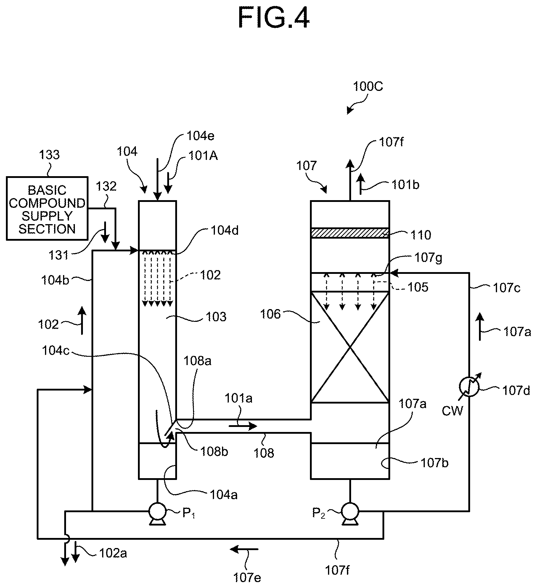
Third Embodiment
[0052] FIG. 4 is a schematic view of an air pollution control unit according to a third embodiment. The same reference numerals will be used for the same features as in the first embodiment, and overlaps will be omitted in the description of such features. As illustrated in FIG. 3, the air pollution control unit 1000 according to the third embodiment is designed to cope with cases where the gas introduced into the gas washing column 104 contains sulfur oxide in addition to particles.
[0053] In the third embodiment, gas 101A containing particles and sulfur oxide is introduced into the gas washing column 104 through the gas introduction line 104e. Furthermore, a basic compound supply section 133 is disposed on the washing liquid circulation line 104b, and a basic compound (for example, NaOH, Na.sub.2CO.sub.3, Ca(OH).sub.2, or CaCO.sub.3) 131 is supplied therefrom through a supply line 132.
[0054] The basic compound 131 is mixed into the washing liquid 102, and the nozzle 104d sprays the liquid of the mixture. The mist sprayed from the nozzle 104d performs both dedusting and desulfurization during gas cleaning.
[0055] The above configuration allows for simultaneous dedusting and desulfurization in the gas washing column 104, and thus eliminates the need to install a separate sulfur oxide removing device.
Fourth Embodiment
[0056] FIG. 5 is a schematic view of a CO.sub.2 recovery unit including an air pollution control unit according to a fourth embodiment. The same reference numerals will be used for the same features as in the first embodiment, and overlaps will be omitted in the description of such features. The CO.sub.2 recovery unit 10 of the fourth embodiment includes: the air pollution control unit 100C of the third embodiment into which gas 101A containing particles and sulfur oxide is introduced; a gas exhausting line 12 through which treated gas 101b discharged from the gas cooling column 107 is exhausted; a CO.sub.2 absorber 14 in which the cooled gas is introduced through the gas exhausting line 12 and CO.sub.2 in the cooled gas and CO.sub.2 absorbent (lean solution) 13 are brought into contact with each other, and thereby CO.sub.2 is removed; an absorbent regenerator 17 in which the CO.sub.2 absorbent that has absorbed CO.sub.2 (rich solution) 15 is regenerated with steam from a reboiler 16; a rich solution supply line 18 through which the rich solution 15 is drawn from the CO.sub.2 absorber 14 and is introduced to the absorbent regenerator 17; and a lean solution supply line 20 through which the CO.sub.2 absorbent (lean solution) 19 regenerated by releasing CO.sub.2 in the absorbent regenerator 17 is drawn from the absorbent regenerator 17 and the CO.sub.2 absorbent 19 is introduced into the CO.sub.2 absorber 14 to be reused as the CO.sub.2 absorbent.
[0057] In a CO.sub.2 recovery method using the CO.sub.2 recovery unit 10, first, gas 101A which contains particles, particles containing CO.sub.2, and sulfur oxide is fed to the gas washing column 104 in the air pollution control unit 100C and is cleaned and dedusted with the washing liquid 102. The cleaned gas 101a is introduced through the gas communication path 108 into the gas cooling column 107, cooled with the cooling liquid 105, and fed as the treated gas 101b to the CO.sub.2 absorber 14 through the gas exhausting line 12.
[0058] In the CO.sub.2 absorber 14, the treated gas 101b is brought into countercurrent contact with the CO.sub.2 absorbent 13 according to the fourth embodiment that is amine-based absorbent, and CO.sub.2 in the treated gas 101b is absorbed in the CO.sub.2 absorbent 13 by chemical reaction. CO.sub.2-free flue gas 101d from which CO.sub.2 has been removed in the CO.sub.2 absorber 14 is brought into gas-liquid contact with cleaning water 22 supplied from a nozzle in a washing section 21 in the CO.sub.2 absorber 14, the cleaning water being circulated and containing the CO.sub.2 absorbent 13, and the CO.sub.2 absorption component entrained with the CO.sub.2-free flue gas 101d is recovered, the gas being then emitted from the column top out of the system. Furthermore, the rich solution 15 that has absorbed CO.sub.2 is pressurized with a rich solution pump 23, heated in a rich-lean solution heat exchanger 24 using the lean solution 19 regenerated in the absorbent regenerator 17, and supplied to the absorbent regenerator 17.
[0059] The rich solution 15 emitted from an upper portion of the absorbent regenerator 17 into the absorbent regenerator 17 is caused to undergo endothermic reaction by water vapor from the reboiler 16 that is supplied through a bottom portion of the absorbent regenerator 17, and releases most of the absorbed CO.sub.2. The CO.sub.2 absorbent that has released part or most of the absorbed CO.sub.2 in the absorbent regenerator 17 is called a semi-lean solution. The semi-lean solution is regenerated to the CO.sub.2 absorbent (lean solution) 19 from which substantially all CO.sub.2 has been completely removed by the time the CO.sub.2 absorbent reaches the bottom portion of the absorbent regenerator 17. Part of the lean solution 19 is heated with the reboiler 16 and supplies water vapor to the inside of the absorbent regenerator 17.
[0060] On the other hand, CO.sub.2-containing gas 31 released from the rich solution 15 and the semi-lean solution in the regenerator is led out through the top portion of the absorbent regenerator 17 together with the water vapor, the water vapor being condensed with a condenser 32, and the condensed water 34 and the CO.sub.2 gas 35 are separated from each other in a separation drum 33. The CO.sub.2 gas 35 separated is passed through a separation drum which is not illustrated, and is thereafter injected into oilfields using enhanced oil recovery (EOR) or is reserved into aquifers to address global warming. The condensed water 34, which has been separated from the CO.sub.2-containing gas 31 entraining water vapor and been refluxed at the separation drum 33, is supplied to the upper portion of the absorbent regenerator 17 by a reflux water circulation pump 36 and is also added to the cleaning water 22 to be supplied to the absorber 14. The regenerated CO.sub.2 absorbent (lean solution) 19 is cooled in the rich-lean solution heat exchanger 24 using the rich solution 15, subsequently pressurized with a lean solution pump 37, further cooled in a lean solution cooler 38, and thereafter supplied into the CO.sub.2 absorber 14. The description of the embodiment is only illustrative of the overview of the embodiment, and omits some of the accompanying devices.
[0061] In the fourth embodiment, dedusting and desulfurization can be performed simultaneously in the gas washing column 104. Furthermore, because the treated gas 101b that has been cooled in the gas cooling column 107 and flows into the CO.sub.2 absorber 14 contains a reduced amount of particles, an accumulation rate of collected particles in the CO.sub.2 absorbent 13 used in the CO.sub.2 absorber 14 (the CO.sub.2 absorbent 13 is circulated and is used repeatedly while absorbing and releasing CO.sub.2) is reduced. As a result, the CO.sub.2 recovery unit 10 can prevent problems, such as fouling and clogging, caused by particles attached to the equipment.
[0062] In the fourth embodiment, the gas that flows into the CO.sub.2 absorber 14 contains a reduced amount of particles, and thus the emission of CO.sub.2 absorbent components, being absorbed in water attached around the particles, that are entrained with the outlet gas from the CO.sub.2 absorber 14 is reduced.
[0063] The fourth embodiment that involves the air pollution control unit 100C illustrated in FIG. 4 may further include the liquid level meter 120 of the second embodiment to cope with changes in gas flow velocity.
[0064] A CO.sub.2 recovery method according to the fourth embodiment includes: a cleaning and desulfurization step in which particle-containing gas 101 containing sulfur oxide and CO.sub.2 is introduced into the gas washing column 104, a basic compound 131 is supplied into the washing liquid 102 that is being circulated, and the particle-containing gas 101 is dedusted and desulfurized; a cooling step in which the cleaned gas 101a resulting from the dedusting and desulfurization is cooled in the gas cooling column 107, and at the same time water in the cleaned gas 101a is condensed with cooling liquid 105 and thereby condensed water 107a is obtained; a washing liquid replenishing step in which the condensed water 107a obtained is supplied to the gas washing column 104 to replenish the washing liquid 102; a CO.sub.2 absorbing step in which the treated gas resulting from the gas cooling is introduced into the CO.sub.2 absorber 14, and CO.sub.2 in the cooled gas and CO2 absorbent 13 are brought into contact with each other, and thereby CO.sub.2 is removed; a CO.sub.2 absorbent regeneration step in which the rich solution 15 that has absorbed CO.sub.2 is regenerated with steam from the reboiler; and a step in which the CO.sub.2 absorbent is circulated for reuse between the CO.sub.2 absorber 14 and the absorbent regenerator 17 through circulation lines.
[0065] With this CO.sub.2 recovery method, dedusting and desulfurization can be performed simultaneously in the gas washing column 104.
[0066] Furthermore, because the treated gas 101b that has been cooled in the gas cooling column 107 and flows into the CO.sub.2 absorber 14 contains a reduced amount of particles, an accumulation rate of collected particles in the CO.sub.2 absorbent 13 used in the CO.sub.2 absorber 14 is reduced. As a result, the CO.sub.2 recovery unit 10 can prevent problems, such as fouling and clogging, caused by particles attached to the equipment.
REFERENCE SIGNS LIST
[0067] 10 CO.sub.2 RECOVERY UNIT
[0068] 12 GAS EXHAUSTING LINE
[0069] 13 CO.sub.2 ABSORBENT (LEAN SOLUTION)
[0070] 14 CO.sub.2 ABSORBER
[0071] 15 CO.sub.2 ABSORBENT (RICH SOLUTION)
[0072] 16 REBOILER
[0073] 17 ABSORBENT REGENERATOR
[0074] 18 RICH SOLUTION SUPPLY LINE
[0075] 19 CO.sub.2 ABSORBENT (LEAN SOLUTION)
[0076] 20 LEAN SOLUTION SUPPLY LINE
[0077] 100A-100C AIR POLLUTION CONTROL UNITS
[0078] 101 PARTICLE-CONTAINING GAS
[0079] 101A GAS CONTAINING PARTICLES AND SULFUR OXIDE
[0080] 102 WASHING LIQUID
[0081] 103 GAS CLEANING SECTION
[0082] 104 GAS WASHING COLUMN
[0083] 105 COOLING LIQUID
[0084] 106 GAS COOLING SECTION
[0085] 107 GAS COOLING COLUMN
[0086] 108 GAS COMMUNICATION PATH
* * * * *
D00000
D00001
D00002
D00003
D00004
D00005
XML
uspto.report is an independent third-party trademark research tool that is not affiliated, endorsed, or sponsored by the United States Patent and Trademark Office (USPTO) or any other governmental organization. The information provided by uspto.report is based on publicly available data at the time of writing and is intended for informational purposes only.
While we strive to provide accurate and up-to-date information, we do not guarantee the accuracy, completeness, reliability, or suitability of the information displayed on this site. The use of this site is at your own risk. Any reliance you place on such information is therefore strictly at your own risk.
All official trademark data, including owner information, should be verified by visiting the official USPTO website at www.uspto.gov. This site is not intended to replace professional legal advice and should not be used as a substitute for consulting with a legal professional who is knowledgeable about trademark law.