Systems And Methods For Creating An Interatrial Shunt
NAE; Nir ; et al.
U.S. patent application number 16/876640 was filed with the patent office on 2020-11-26 for systems and methods for creating an interatrial shunt. This patent application is currently assigned to V-Wave Ltd.. The applicant listed for this patent is V-Wave Ltd.. Invention is credited to Neal EIGLER, Werner HAFELFINGER, Nir NAE, Lior ROSEN, Erez ROZENFELD, Tal WEISINGER, James WHITING.
| Application Number | 20200368505 16/876640 |
| Document ID | / |
| Family ID | 1000004869398 |
| Filed Date | 2020-11-26 |


View All Diagrams
| United States Patent Application | 20200368505 |
| Kind Code | A1 |
| NAE; Nir ; et al. | November 26, 2020 |
SYSTEMS AND METHODS FOR CREATING AN INTERATRIAL SHUNT
Abstract
A device for precise control of blood flow across an interatrial septum is provided. The device includes a sheath having a first set of openings disposed within a first atrium while a second set of openings is disposed within a second atrium. An actuator may be actuated to move an inner sleeve within the sheath to modify the area of second set of openings to permit blood to flow between the first and second atria responsive to a pressure gradient across the interatrial septum via the first and second openings at a blood flow rate corresponding with the area of the second set of openings of the sheath. In addition, the patient's hemodynamics responsive to the shunting of blood across the interatrial septum at each incremental area of the opening may be monitored for selecting a specific sized implantable interatrial shunt for the patient.
| Inventors: | NAE; Nir; (Binyamina, IL) ; WEISINGER; Tal; (Haifa, IL) ; ROSEN; Lior; (Or Akiva, IL) ; WHITING; James; (Los Angeles, CA) ; EIGLER; Neal; (Agoura Hills, CA) ; HAFELFINGER; Werner; (Thousand Oaks, CA) ; ROZENFELD; Erez; (Shoham, IL) | ||||||||||
| Applicant: |
|
||||||||||
|---|---|---|---|---|---|---|---|---|---|---|---|
| Assignee: | V-Wave Ltd. Caesarea IL |
||||||||||
| Family ID: | 1000004869398 | ||||||||||
| Appl. No.: | 16/876640 | ||||||||||
| Filed: | May 18, 2020 |
Related U.S. Patent Documents
| Application Number | Filing Date | Patent Number | ||
|---|---|---|---|---|
| 62850511 | May 20, 2019 | |||
| Current U.S. Class: | 1/1 |
| Current CPC Class: | A61M 25/1011 20130101; A61M 2230/30 20130101; A61M 27/002 20130101; A61B 2018/0022 20130101; A61M 2205/3334 20130101; A61M 2210/125 20130101; A61M 2230/205 20130101; A61B 2018/00577 20130101; A61M 2205/3331 20130101; A61B 18/1492 20130101; A61B 2018/0038 20130101; A61M 2230/20 20130101; A61M 25/09 20130101 |
| International Class: | A61M 27/00 20060101 A61M027/00; A61B 18/14 20060101 A61B018/14; A61M 25/10 20060101 A61M025/10 |
Claims
1. A device for control of blood flow across a patient's interatrial septum, the device comprising: a sheath having a proximal region, a distal region and a lumen therebetween, the distal region having a first set of one or more openings and a second set of one or more openings spaced apart from the first set of one or more openings a distance greater than a thickness of the interatrial septum such that the first set of one or more openings is configured to be disposed within a first atrium of the patient while the second set of one or more openings is disposed in a second atrium of the patient; an actuator configured to be actuated to modify an area of an opening of the second set of one or more openings of the sheath, such that blood is permitted to flow between the first and second atria responsive to a pressure gradient across the interatrial septum via the first and second sets of one or more openings and the sheath lumen therebetween, at a blood flow rate corresponding with the area of the opening of the second set of one or more openings of the sheath.
2. The device of claim 1, wherein the second set of one or more openings of the sheath comprise at least one of a circular, elliptical, or elongated slot shape, or any combination thereof.
3. The device of claim 1, wherein the second set of one or more openings of the sheath is distributed symmetrically about an outer surface of the sheath.
4. The device of claim 1, wherein the second set of one or more openings of the sheath is distributed asymmetrically about an outer surface of the sheath.
5. The device of claim 1, further comprising: an inner sleeve having a proximal region and a distal region having an outer diameter equal to an inner diameter of the sheath, the inner sleeve moveably disposed within the lumen of the sheath, wherein the actuator is configured to be actuated to modify the area of the opening of the second set of one or more openings of the sheath by moving the inner sleeve relative to the sheath by an incremental amount such that blood is permitted to flow between the first and second atria responsive to a pressure gradient across the interatrial septum via the first and second sets of one or more openings and the sheath lumen therebetween, at a blood flow rate corresponding with the area of the opening of the second set of one or more openings of the sheath.
6. The device of claim 5, wherein the inner sleeve further comprises one or more flushing ports in fluid communication with a source of flushing fluid via one or more flushing lumens of the inner sleeve, the one or more flushing ports configured to eject the flushing fluid therethrough to prevent accumulation of blood clots at the second set of one or more openings of the sheath.
7. The device of claim 5, wherein the inner sleeve comprises a guidewire lumen sized and shaped for receiving a guidewire.
8. The device of claim 7, further comprising a pressure sensor guidewire configured to be disposed within the guidewire lumen of the inner sleeve, the pressure sensor guidewire operatively coupled to an external controller and configured to measure pressure within the first atrium and to transmit a signal indicative of the measured pressure to the external controller.
9. The device of claim 1, further comprising: an inner sleeve having a proximal region, a distal region having a first set of one or more apertures in fluid communication with the first set of one or more openings of the sheath, and a lumen extending therebetween, the inner sleeve moveably disposed within the lumen of the sheath and comprising a second set of one or more apertures sized and shaped to register with the second set of one or more openings of the sheath, wherein the actuator is configured to be actuated to modify the area of the opening of the second set of one or more openings of the sheath by moving the inner sleeve relative to the sheath to register the second set of one or more apertures of the inner sleeve with the second set of one or more openings of the sheath by a predetermined amount such that blood is permitted to flow between the first and second atria responsive to a pressure gradient across the interatrial septum via the first and second sets of one or more openings and apertures and the inner sleeve lumen therebetween, at a blood flow rate corresponding with the predetermined amount of registration between the second set of one or more apertures of the inner sleeve and the second set of one or more openings of the sheath.
10. The device of claim 9, wherein the sheath further comprises a third set of one or more openings spaced apart from the second set of one or more openings such that the third set of one or more openings is configured to be disposed within an inferior vena cava of the patient while the first set of one or more openings is disposed in the first atrium, wherein the inner sleeve further comprises a third set of one or more apertures sized and shaped to register with the third set of one or more openings of the sheath, and wherein the actuator is further configured to be actuated to move the inner sleeve relative to the sheath to register the third set of one or more apertures of the inner sleeve with the third set of one or more openings of the sheath by a predetermined amount such that blood is permitted to flow between the inferior vena cava and the first atrium responsive to a pressure gradient between the inferior vena cava and the first atrium via the first and third sets of one or more openings and apertures and the inner sleeve lumen therebetween.
11. The device of claim 10, wherein, when the third set of one or more apertures completely register with the third set of one or more openings, the second set of one or more apertures of the inner sleeve are not registered with the second set of one or more openings of the sheath.
12. The device of claim 1, wherein the actuator is configured to be actuated to incrementally select the area of the opening of the second set of one or more openings of the sheath, such that the blood flow rate of the blood flow between the first and second atria to the at each increment corresponds with a blood flow rate of blood flow through a predetermined sized interatrial shunt implanted within the patient's interatrial septum.
13. The device of claim 12, wherein the area of the opening of the second set of one or more openings of the sheath corresponds with the blood flow rate of blood flow through the predetermined sized interatrial shunt having a diameter between 4 to 8 mm.
14. The device of claim 1, further comprising one or more sensors disposed within the lumen of the sheath and operatively coupled to an external controller, the one or more sensors configured to measure one or more physiological parameters and to transmit a signal indicative of the measured physiological parameter to the external controller.
15. The device of claim 14, wherein the one or more physiological parameters comprise at least one of pressure, blood flow rate, blood flow velocity, or oximetry.
16. The device of claim 1, further comprising an anchor disposed at the distal region of the sheath, the anchor configured to facilitate fixation of the sheath to the patient's interatrial septum.
17. The device of claim of 16, wherein the anchor comprises a balloon, configured to prevent movement of the sheath relative to the patient's interatrial septum.
18. The device of claim of 17, wherein the balloon is configured to be inflated within the first atrium, thereby preventing proximal movement of the sheath relative to the patient's interatrial septum.
19. The device of claim of 18, further comprising a second balloon configured to be inflated within the second atrium, wherein the first and second balloons, when inflated, sandwich the interatrial septum.
20. The device of claim of 17, wherein the balloon is configured to be inflated within the second atrium, thereby preventing distal movement of the sheath relative to the patient's interatrial septum.
21. The device of claim of 17, wherein the balloon comprises a metal coil disposed on its outer surface, the metal coil configured to emit RF energy sufficient to ablate tissue adjacent to the metal coil.
22. The device of claim of 16, wherein the anchor comprises deployment tines.
23. The device of claim 1, further comprising a metal coil disposed on an outer surface of the sheath, the metal coil configured to emit RF energy sufficient to ablate tissue adjacent to the metal coil to induce an interatrial shunt.
24. The device of claim 23, wherein the metal coil is disposed on the outer surface of the sheath proximal to the second set of one or more openings.
25. The device of claim 23, further comprising one or more additional metal coils, wherein each of the metal coils are configured to emit RF energy sufficient to ablate tissue adjacent to the respective metal coil to induce an interatrial shunt having a predetermined diameter.
26. The device of claim 25, wherein a graded portion of the sheath comprises an outer surface having a cross-sectional area that increases in a distal direction, each of the metal coils disposed along the graded portion of the sheath at a position corresponding the predetermined diameter.
27. A method for controlling of blood flow across a patient's interatrial septum, the method comprising: creating a puncture through the patient's interatrial septum; delivering a sheath across the puncture such that a first set of one or more openings of the sheath is disposed within a first atrium of the patient and a second set of one or more openings of the sheath is disposed within a second atrium of the patient; permitting blood to flow between the first and second atria responsive to a pressure gradient across the interatrial septum via the first and second set of one or more openings and a lumen of the sheath; modifying an area of an opening of the second set of one or more openings such that blood is permitted to flow between the first and second atria via the first and second set of one or more openings and a lumen of the sheath at a modified blood flow rate; and selecting an interatrial shunt for implantation in the patient's interatrial septum based on the permitting and the modifying.
Description
CROSS-REFERENCE TO RELATED APPLICATIONS
[0001] This application claims the benefit of priority of U.S. Provisional Patent Application No. 62/850,511, filed May 20, 2019, the entire contents of which are incorporated herein by reference.
FIELD OF THE INVENTION
[0002] This application generally relates to systems and methods for creating an interatrial shunt to redistribute blood from one cardiac chamber to another to address pathologies such as heart failure ("HF"), myocardial infarction ("MI") and pulmonary arterial hypertension ("PAH").
BACKGROUND OF THE INVENTION
[0003] Heart failure is the physiological state in which cardiac output is insufficient to meet the needs of the body or to do so only at a higher filing pressure. There are many underlying causes of HF, including myocardial infarction, coronary artery disease, valvular disease, hypertension, and myocarditis. Chronic heart failure is associated with neurohormonal activation and alterations in autonomic control. Although these compensatory neurohormonal mechanisms provide valuable support for the heart under normal physiological circumstances, they also play a fundamental role in the development and subsequent progression of HF.
[0004] For example, one of the body's main compensatory mechanisms for reduced blood flow in HF is to increase the amount of salt and water retained by the kidneys. Retaining salt and water, instead of excreting it via urine, increases the volume of blood in the bloodstream and helps to maintain blood pressure. However, the larger volumes of blood also cause the heart muscle, particularly the ventricles, to become enlarged. As the heart chambers become enlarged, the wall thickness decreases and the heart's contractions weaken, causing a downward spiral in cardiac function. Another compensatory mechanism is vasoconstriction of the arterial system, which raises the blood pressure to help maintain adequate perfusion, thus increasing the load that the heart must pump against.
[0005] In low ejection fraction ("EF") heart failure, high pressures in the heart result from the body's attempt to maintain the high pressures needed for adequate peripheral perfusion. However, as the heart weakens as a result of such high pressures, the disorder becomes exacerbated. Pressure in the left atrium may exceed 25 mmHg, at which stage, fluids from the blood flowing through the pulmonary circulatory system transudate or flow out of the pulmonary capillaries into the pulmonary interstitial spaces and into the alveoli, causing lung congestion and if untreated the syndrome of acute pulmonary edema and death.
[0006] Table 1 lists typical ranges of right atrial pressure ("RAP"), right ventricular pressure ("RVP"), left atrial pressure ("LAP"), left ventricular pressure ("LVP"), cardiac output ("CO"), and stroke volume ("SV") for a normal heart and for a heart suffering from HF. In a normal heart beating at around 70 beats/minute, the stroke volume needed to maintain normal cardiac output is about 60 to 100 milliliters. When the preload, after-load, and contractility of the heart are normal, the pressures required to achieve normal cardiac output are listed in Table 1. In a heart suffering from HF, the hemodynamic parameters change (as shown in Table 1) to maintain peripheral perfusion.
TABLE-US-00001 TABLE 1 Parameter Normal Range HF Range RAP (mmHg) 2-6 6-20 RVSP (mmHg) 15-25 20-80 LAP (mmHg) 6-12 15-50 LVEDP (mmHg) 6-12 15-50 CO (liters/minute) 4-8 2-6 SV (milliliters/beat) 60-100 30-80
[0007] HF is generally classified as either systolic heart failure ("SHF") or diastolic heart failure ("DHF"). In SHF, the pumping action of the heart is reduced or weakened. A common clinical measurement is the ejection fraction, which is a function of the blood ejected out of the left ventricle (stroke volume) divided by the maximum volume in the left ventricle at the end of diastole or relaxation phase. A normal ejection fraction is greater than 50%. Systolic heart failure generally causes a decreased ejection fraction of less than 40%. Such patients have heart failure with reduced ejection fraction ("HFrEF"). A patient with HFrEF may usually have a larger left ventricle because of a phenomenon called "cardiac remodeling" that occurs secondarily to the higher ventricular pressures.
[0008] In DHF, the heart generally contracts normally, with a normal ejection fraction, but is stiffer, or less compliant, than a healthy heart would be when relaxing and filling with blood. Such patients are said to have heart failure with preserved ejection fraction ("HFpEF"). This stiffness may impede blood from filling the heart and produce backup into the lungs, which may result in pulmonary venous hypertension and lung edema. HFpEF is more common in patients older than 75 years, especially in women with high blood pressure.
[0009] Both variants of HF have been treated using pharmacological approaches, which typically involve the use of vasodilators for reducing the workload of the heart by reducing systemic vascular resistance, as well as diuretics, which inhibit fluid accumulation and edema formation, and reduce cardiac filling pressure. No pharmacological therapies have been shown to improve morbidity or mortality in HFpEF whereas several classes of drugs have made an important impact on the management of patients with HFrEF, including renin-angiotensin antagonists, beta blockers, and mineralocorticoid antagonists. Nonetheless, in general, HF remains a progressive disease and most patients have deteriorating cardiac function and symptoms over time. In the U.S., there are over 1 million hospitalizations annually for acutely worsening HF and mortality is higher than for most forms of cancer.
[0010] In more severe cases of HFrEF, assist devices such as mechanical pumps are used to reduce the load on the heart by performing all or part of the pumping function normally done by the heart. Chronic left ventricular assist devices ("LVAD"), and cardiac transplantation, often are used as measures of last resort. However, such assist devices typically are intended to improve the pumping capacity of the heart, to increase cardiac output to levels compatible with normal life, and to sustain the patient until a donor heart for transplantation becomes available. Such mechanical devices enable propulsion of significant volumes of blood (liters/min), but are limited by a need for a power supply, relatively large pumps, and pose a risk of hemolysis, thrombus formation, and infection. Temporary assist devices, intra-aortic balloons, and pacing devices have also been used.
[0011] Various devices have been developed using stents to modify blood pressure and flow within a given vessel, or between chambers of the heart. For example, U.S. Pat. No. 6,120,534 to Ruiz is directed to an endoluminal stent for regulating the flow of fluids through a body vessel or organ, for example, for regulating blood flow through the pulmonary artery to treat congenital heart defects. The stent may include an expandable mesh having lobed or conical portions joined by a constricted region, which limits flow through the stent. The mesh may comprise longitudinal struts connected by transverse sinusoidal or serpentine connecting members. Ruiz is silent on the treatment of HF or the reduction of left atrial pressure.
[0012] U.S. Pat. No. 6,468,303 to Amplatz et al. describes a collapsible medical device and associated method for shunting selected organs and vessels. Amplatz describes that the device may be suitable to shunt a septal defect of a patient's heart, for example, by creating a shunt in the atrial septum of a neonate with hypoplastic left heart syndrome ("HLHS"). That patent also describes that increasing mixing of pulmonary and systemic venous blood improves oxygen saturation, and that the shunt may later be closed with an occluding device. Amplatz is silent on the treatment of HF or the reduction of left atrial pressure, as well as on means for regulating the rate of blood flow through the device.
[0013] Implantable interatrial shunt devices have been successfully used in patients with severe symptomatic heart failure. By diverting or shunting blood from the left atrium ("LA") to the right atrium ("RA"), the pressure in the left atrium is lowered or prevented from elevating as high as it would otherwise (left atrial decompression). Such an accomplishment would be expected to prevent, relieve, or limit the symptoms, signs, and syndromes associated with pulmonary congestion. These include severe shortness of breath, pulmonary edema, hypoxia, the need for acute hospitalization, mechanical ventilation, and death.
[0014] Shunt flow is generally governed by the pressure gradient between the atria, and by the fluid mechanical properties of the shunt device. The latter are typically affected by the shunt's geometry and material composition. For example, the general flow properties of similar shunt designs have been shown to be related to the mean interatrial pressure gradient and the effective orifice diameter.
[0015] Percutaneous implantation of interatrial shunts generally requires transseptal catheterization immediately preceding shunt device insertion. The transseptal catheterization system is placed, from an entrance site in the femoral vein, across the interatrial septum in the region of fossa ovalis ("FO"), which is the central and thinnest region of the interatrial septum. This is the same general location where a congenital secundum atrial septal defect ("ASD") would be located. The FO in adults is typically 15-20 mm in its major axis dimension and <3 mm in thickness, but in certain circumstances may be up to 10 mm thick. LA chamber access may be achieved using a host of different techniques familiar to those skilled in the art, including but not limited to: needle puncture, stylet puncture, screw needle puncture, and radiofrequency ablation. The passageway between the two atria is dilated to facilitate passage of a shunt device having a desired orifice size. Dilation generally is accomplished by advancing a tapered sheath/dilator catheter system or inflation of an angioplasty-type balloon across the FO.
[0016] U.S. Patent Publication No. 2005/0165344 to Dobak, III describes apparatus for treating heart failure that includes a tubular conduit having an emboli filter or valve, the device configured to be positioned in an opening in the atrial septum of the heart to allow flow from the left atrium into the right atrium. Dobak discloses that shunting of blood may reduce left atrial pressures, thereby preventing pulmonary edema and progressive left ventricular dysfunction, and reducing LVEDP. Dobak describes that the device may include deployable retention struts, such as metallic arms that exert a slight force on the atrial septum on both sides and pinch or clamp the device to the septum.
[0017] U.S. Pat. No. 9,034,034 to Nitzan, the entire contents of which are incorporated by reference herein, describes a shunt comprising an hourglass or diabolo outer shape, having a small FO footprint minimizing septal injury, which is expected to minimize pannus growth and obliteration of the shunt lumen. Its one-way valve also is designed to reduce the potential for reverse shunting and paradoxical embolization. The relatively small footprint of the shunt in contact with the septum and encapsulated collapsible nitinol frame is designed to facilitate percutaneous extraction from the septum and retrieval from the body using a standard goose-neck snare and large-bore sheath, thus making the device more easily retrieved. The venturi tube-like inner lumen of the diabolo shape provides better bulk flow characteristics, permitting a smaller orifice for the same amount of flow compared to orifice-plate shunts. And finally, the small footprint on the FO and the hourglass shape are designed to facilitate accurate placement and retention during implantation. This geometry also minimizes interference with normal motion of the interatrial septum, and the small footprint provides space surrounding the shunt for other potential interventional procedures that require transseptal catheterization.
[0018] One embodiment of the Nitzan design, manufactured by V-Wave, Ltd (Caesarea, Israel), designed to support unidirectional left-to-right flow, comprises a self-expanding frame constructed from a laser-cut nitinol tube. The frame includes five sinusoidal circumferential struts interconnected by six longitudinal bars. The frame is heat-set so that it has an asymmetrical hourglass shape or a diabolo shape. The shunt is deployed so that the neck (5.3 mm outer diameter) is placed across the FO and secured in place by its external surface geometry. The shunt's widest portion has a conical shape with an approximately 14.3 mm outer diameter at the LA end of the shunt, which serves as an "entry" port on the distal end of the entry funnel. The entry funnel is deployed in the left atrium, and registers the neck of the shunt to the region of the FO. A second, slightly narrower bell-shaped portion forms the exit portion of the shunt, which expands to a maximum outer diameter of 11.4 mm at the RA end of the shunt. The shunt does not require flanges, discs, or tissue anchors to secure it in place. Septal retention is achieved without applying persistent pressure, tension or rubbing contact on the tissue adjoining the device neck.
[0019] The V-Wave shunt has a single inner lumen where flow is entrained into the entry funnel in the LA and passes through the constricted neck having a 5.1 mm inner diameter, which resembles a venturi-type orifice, and then exits through a bioprosthetic valve positioned near the RA end of the shunt. The entry funnel and the central neck region are encapsulated with expanded polytetrafluoroethylene ("ePTFE") to form a skirt or cover over the frame. The skirt is designed to facilitate laminar flow and limit pannus ingrowth during device healing. The exit bell-shaped portion contains three, glutaraldehyde-fixed, porcine pericardial leaflets sutured to the frame at the right atrial extent of the ePTFE encapsulation. The leaflets are designed to create a smooth exit channel and remain in the open position, closing only when the RA pressure exceeds LA pressure by 1-2 mmHg, thus preventing reverse right-to-left shunting.
[0020] U.S. Pat. Nos. 10,076,403 and 10,251,740 to Eigler, the entire contents of each of which are incorporated by reference herein, describe an interatrial shunt designed for regulating blood pressure between a patient's left and right atrium, while preventing pannus formation from narrowing the lumen in the neck region of the shunt.
[0021] The size of the shunt, e.g., the diameter of the passageway through which blood flows between the left and right atrium, may have different effects on the patient's hemodynamics and systemic oxygen delivery. For example, too small a shunt will have no benefit, whereas too large a shunt may diminish systemic oxygen deliver due to too large an admixture of desaturate blood in patient with PAH, or create right-sided volume overload and right ventricular failure in a patient with left ventricular HF. In addition, each patient's physiology is unique and thus, each patient may require a specific sized interatrial shunt for optimal treatment.
[0022] Therefore, it is desirable to provide devices and methods for creating an interatrial shunt and determining the proper implantable shunt size for each individual patient prior to implanting the permanent shunt within the patient's interatrial septum.
SUMMARY OF THE INVENTION
[0023] The present invention provides systems, devices, and methods for control of blood flow across a patient's interatrial septum. An exemplary device includes a sheath having a proximal region, a distal region and a lumen therebetween. The distal region of the sheath includes a first set of one or more openings and a second set of one or more openings spaced apart from the first set of one or more openings a distance greater than a thickness of the interatrial septum such that the first set of one or more openings is disposed within a first atrium of the patient while the second set of one or more openings is disposed in a second atrium of the patient. For example, the second set of one or more openings of the sheath may have at least one of a circular, elliptical, or rectangular shape, or any combination thereof. In addition, the second set of one or more openings of the sheath may be distributed symmetrically or asymmetrically about an outer surface of the sheath.
[0024] The device further includes an actuator for modifying an area of an opening of the second set of one or more openings of the sheath, such that blood is permitted to flow between the first and second atria responsive to a pressure gradient across the interatrial septum via the first and second sets of one or more openings and the sheath lumen therebetween, at a blood flow rate corresponding with the area of the opening of the second set of one or more openings of the sheath. For example, the actuator may be actuated to incrementally select the area of the opening of the second set of one or more openings of the sheath, such that the blood flow rate of the blood flow between the first and second atria at each increment corresponds with blood flow through a predetermined sized puncture of the patient's interatrial septum, e.g., having a diameter between 4 to 8 mm.
[0025] Further, the device may include an inner sleeve moveably disposed within the lumen of the sheath. The inner sleeve has a proximal region and a distal region having an outer diameter equal to an inner diameter of the sheath. Accordingly, the actuator may be actuated to modify the area of the opening of the second set of one or more openings of the sheath by moving the inner sleeve relative to the sheath by an incremental amount such that blood is permitted to flow between the first and second atria responsive to a pressure gradient across the interatrial septum via the first and second sets of one or more openings and the sheath lumen therebetween, at a blood flow rate corresponding with the area of the opening of the second set of one or more openings of the sheath.
[0026] In addition, the inner sleeve further may include one or more flushing ports in fluid communication with a source of flushing fluid via one or more flushing lumens of the inner sleeve. Thus, the one or more flushing ports may eject the flushing fluid therethrough to prevent accumulation of blood clots at the second set of one or more openings of the sheath. Moreover, the inner sleeve may include a guidewire lumen sized and shaped for receiving a guidewire. Accordingly, the device further may include a pressure sensor guidewire that may be disposed within the guidewire lumen of the inner sleeve. The pressure sensor guidewire may be operatively coupled to an external controller, and may measure pressure within the first atrium and transmit a signal indicative of the measured pressure to the external controller.
[0027] In accordance with one aspect of the present invention, the inner sleeve moveably disposed within the lumen of the sheath has a first set of one or more apertures in fluid communication with the first set of one or more openings of the sheath, and a lumen extending therebetween. The inner sleeve further includes a second set of one or more apertures sized and shaped to register with the second set of one or more openings of the sheath. Accordingly, the actuator may be actuated to modify the area of the opening of the second set of one or more openings of the sheath by moving the inner sleeve relative to the sheath to register the second set of one or more apertures of the inner sleeve with the second set of one or more openings of the sheath by a predetermined amount such that blood is permitted to flow between the first and second atria responsive to a pressure gradient across the interatrial septum via the first and second sets of one or more openings and apertures and the inner sleeve lumen therebetween, at a blood flow rate corresponding with the predetermined amount of registration between the second set of one or more apertures of the inner sleeve and the second set of one or more openings of the sheath.
[0028] Moreover, the sheath further may include a third set of one or more openings spaced apart from the second set of one or more openings such that the third set of one or more openings is disposed within an inferior vena cava of the patient while the first set of one or more openings is disposed in the first atrium during operation of the device. Accordingly, the inner sleeve further includes a third set of one or more apertures sized and shaped to register with the third set of one or more openings of the sheath. Thus, the actuator may be actuated to move the inner sleeve relative to the sheath to register the third set of one or more apertures of the inner sleeve with the third set of one or more openings of the sheath by a predetermined amount such that blood is permitted to flow between the inferior vena cava and the first atrium responsive to a pressure gradient between the inferior vena cava and the first atrium via the first and third sets of one or more openings and apertures and the inner sleeve lumen therebetween. For example, when the third set of one or more apertures completely registers with the third set of one or more openings of the sheath, the second set of one or more apertures of the inner sleeve are not registered with the second set of one or more openings of the sheath, such that blood is permitted to flow between the inferior vena cava and the first atrium, though not between the second atrium and the inferior vena cava.
[0029] The device further may include one or more sensors disposed within the lumen of the sheath and operatively coupled to an external controller. The external controller may include a display and/or user interface such that a physician may manually operate the device. The one or more sensors may measure one or more physiological parameters, e.g., pressure, blood flow rate, blood flow velocity, or oximetry, and transmit a signal indicative of the measured physiological parameter to the external controller. Moreover, the device may include an anchor disposed at the distal region of the sheath for facilitating fixation of the sheath to the patient's interatrial septum. For example, the anchor may be a balloon that may be inflated within the first atrium, thereby preventing proximal movement of the sheath relative to the patient's interatrial septum. Alternatively, the anchor may be a balloon that may be inflated within the second atrium, thereby preventing distal movement of the sheath relative to the patient's interatrial septum. In one embodiment, the anchor may include a first balloon in the first atrium and a second balloon in the second atrium, such that when inflated, the balloons sandwich the interatrial septum. Moreover, the balloon(s) may include a metal coil disposed on its outer surface for transmitting RF energy sufficient to ablate tissue adjacent to the metal coil. Alternatively, or additionally, the anchor may include deployment tines sized and shaped to register on the wall of interatrial septum.
[0030] In accordance with one aspect of the present invention, the device may include a metal coil disposed on an outer surface of the sheath. For example, the metal coil may be disposed on the outer surface of the sheath proximal to the second set of one or more openings. The metal coil may emit RF energy sufficient to ablate tissue adjacent to the metal coil to induce an interatrial shunt.
[0031] In one embodiment, the device may include one or more additional metal coils, such that each of the metal coils may emit RF energy sufficient to ablate tissue adjacent to the respective metal coil to induce an interatrial shunt having a predetermined diameter. For example, a graded portion of the sheath may have an outer surface having a cross-sectional area that increases in a distal direction, such that each of the metal coils are disposed along the graded portion of the sheath at a position corresponding the predetermined diameter.
[0032] In accordance with another aspect of the present invention, a method for controlling blood flow across a patient's interatrial septum is provided. The method may include creating a puncture through the patient's interatrial septum; delivering the sheath across the puncture such that the first set of one or more openings of the sheath is disposed within a first atrium of the patient and the second set of one or more openings of the sheath is disposed within a second atrium of the patient; permitting blood to flow between the first and second atria responsive to a pressure gradient across the interatrial septum via the first and second set of one or more openings and a lumen of the sheath; modifying an area of an opening of the second set of one or more openings such that blood is permitted to flow between the first and second atria via the first and second set of one or more openings and a lumen of the sheath at a modified blood flow rate; and selecting an interatrial shunt for implantation in the patient's interatrial septum based on the permitting and the modifying.
[0033] For example, modifying the area of the opening of the second set of one or more openings may include moving the inner sleeve within the lumen of the sheath by an incremental amount, such that blood is permitted to flow between the first and second atria via the first set of one or more openings of the sheath and the opening provided between the second set of one or more openings of the sheath and the distal region of the inner sleeve at a blood flow rate corresponding with the area of the opening of the second set of one or more openings.
[0034] Additionally, the method may include emitting RF energy to ablate tissue surrounding the puncture to alter tissue healing. For example, emitting RF energy to ablate tissue surrounding the puncture may induce an interatrial shunt having a predetermined diameter. Accordingly, the method further may include moving the sheath relative to the interatrial septum to align the interatrial septum with a metal coil disposed on an outer surface of the sheath, such that emitting RF energy to ablate tissue surrounding the puncture includes emitting RF energy via the metal coil to ablate tissue surrounding the puncture to induce the interatrial shunt having the predetermined diameter.
[0035] When the patient has pulmonary arterial hypertension, blood is permitted to flow from within the right atrium to the left atrium responsive to a pressure gradient across the interatrial septum via the first and second set of one or more openings of the sheath and the sheath lumen. When the patient has heart failure, blood is permitted to flow from within the left atrium to the right atrium responsive to a pressure gradient across the interatrial septum via the first and second set of one or more openings of the sheath and the sheath lumen.
[0036] The method further includes measuring blood flow rate of the blood flow between the first and second atrium, and/or measuring at least one physiological parameter of the patient at each incremental area of the opening of the second set of one or more openings. In accordance with one aspect of the present invention, a signal indicative of the measured physiological parameter may be transmitted to an external controller or display. In another aspect of the present invention, measuring at least one physiological parameter of the patient may be performed by a separate system, such as a cardiac ultrasound machine, pulse oximeter, electrocardiogram, sphygmomanometer or forms of hemodynamic monitoring known to those skilled in the art of patient physiology. Accordingly, the implantable interatrial shunt provided may have a preselected diameter at its neck region based on the signal indicative of the measured physiological parameter.
BRIEF DESCRIPTION OF DRAWINGS
[0037] FIG. 1A illustrates an exemplary device for temporary precision shunting constructed in accordance with the principles of the present invention.
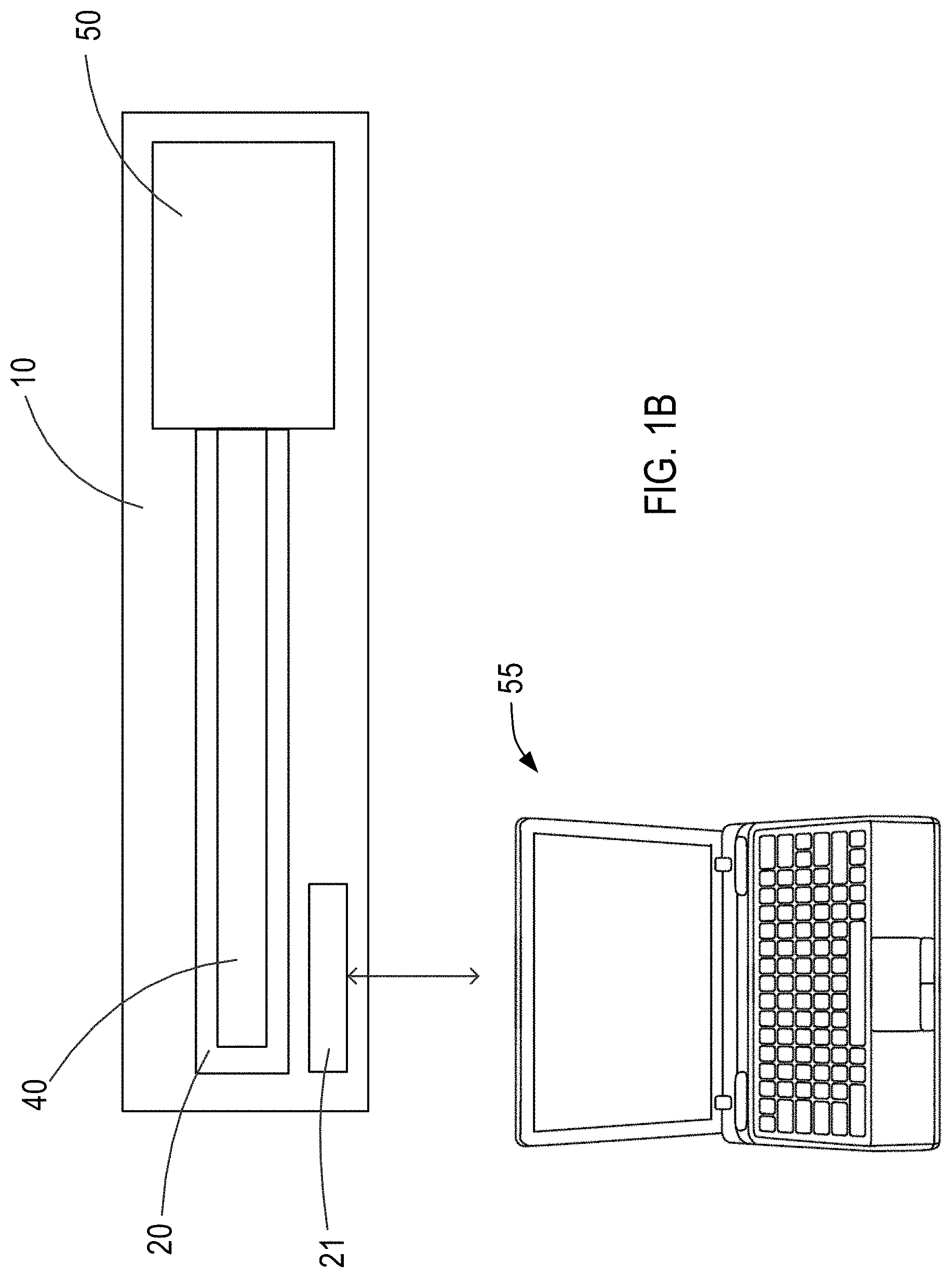
[0038] FIG. 1B is a schematic of an exemplary system including the device of FIG. 1A.
[0039] FIG. 2A illustrates an exemplary sheath of the device of FIG. 1 constructed in accordance with the principles of the present invention.
[0040] FIG. 2B illustrates an alternative exemplary sheath constructed in accordance with the principles of the present invention.
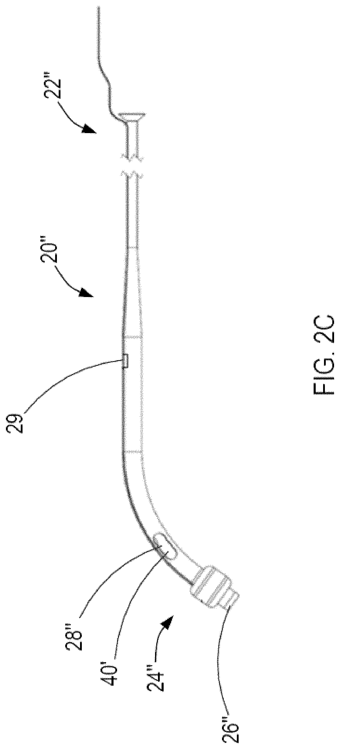
[0041] FIG. 2C illustrates another alternative exemplary sheath constructed in accordance with the principles of the present invention.
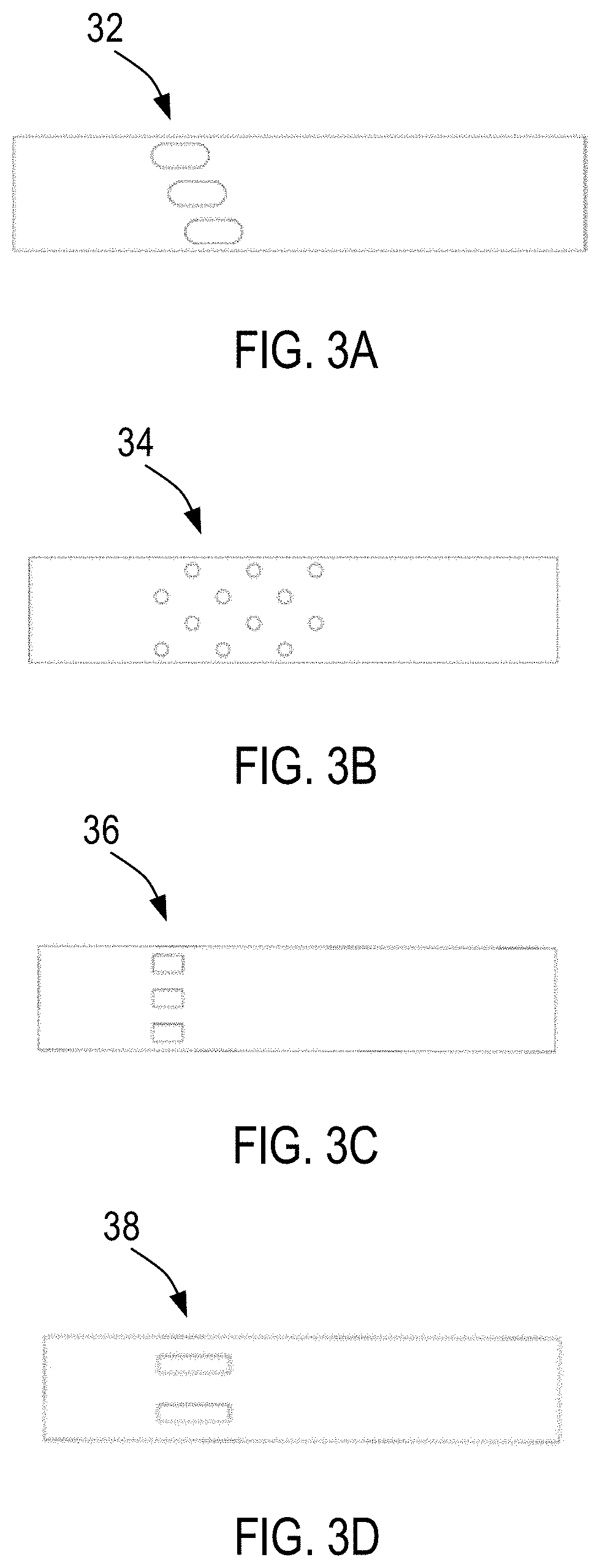
[0042] FIGS. 3A to 3D illustrate various configurations of one or more openings of the sheath constructed in accordance with the principles of the present invention.
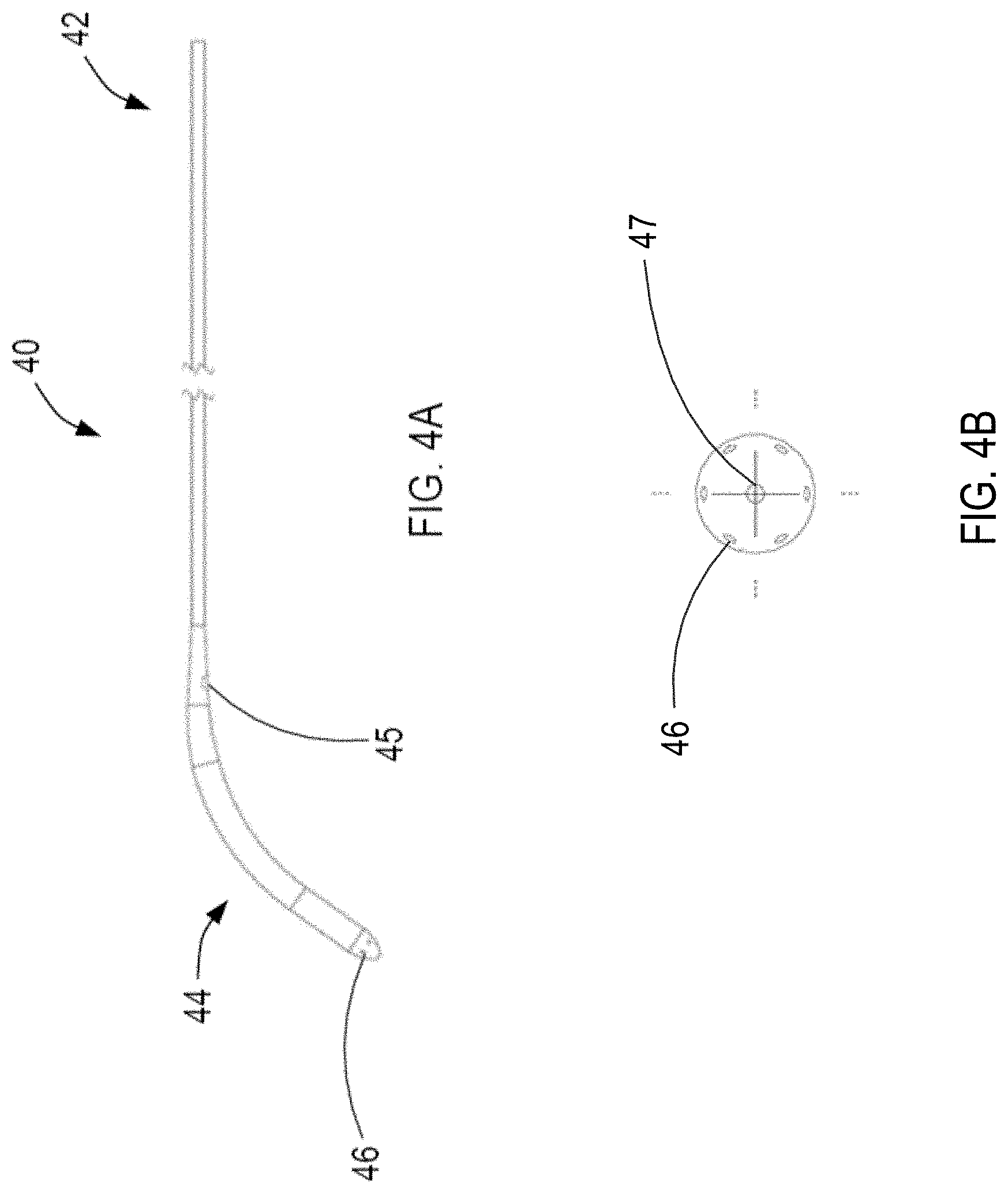
[0043] FIG. 4A illustrates an exemplary inner sleeve of the device of FIG. 1 constructed in accordance with the principles of the present invention, and FIG. 4B illustrates the flushing ports of the inner sleeve of FIG. 4A.
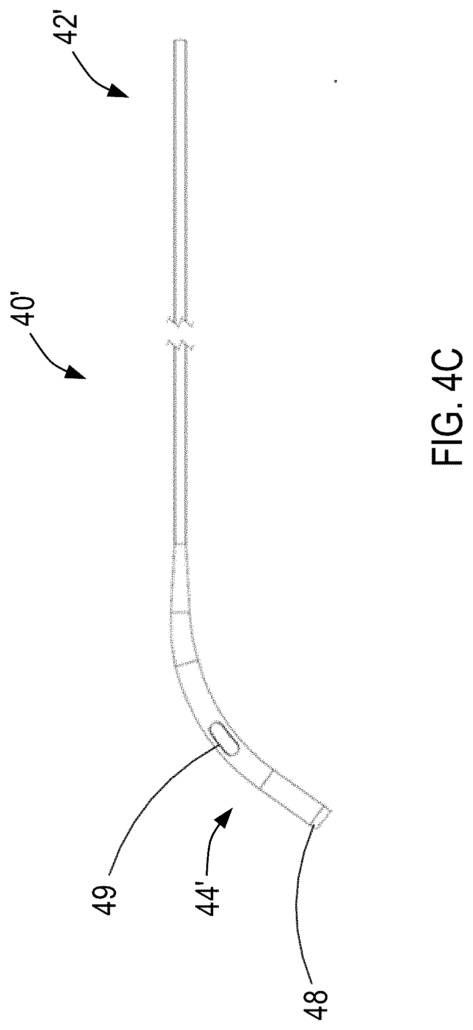
[0044] FIG. 4C illustrated an alternative exemplary inner sleeve constructed in accordance with the principles of the present invention.
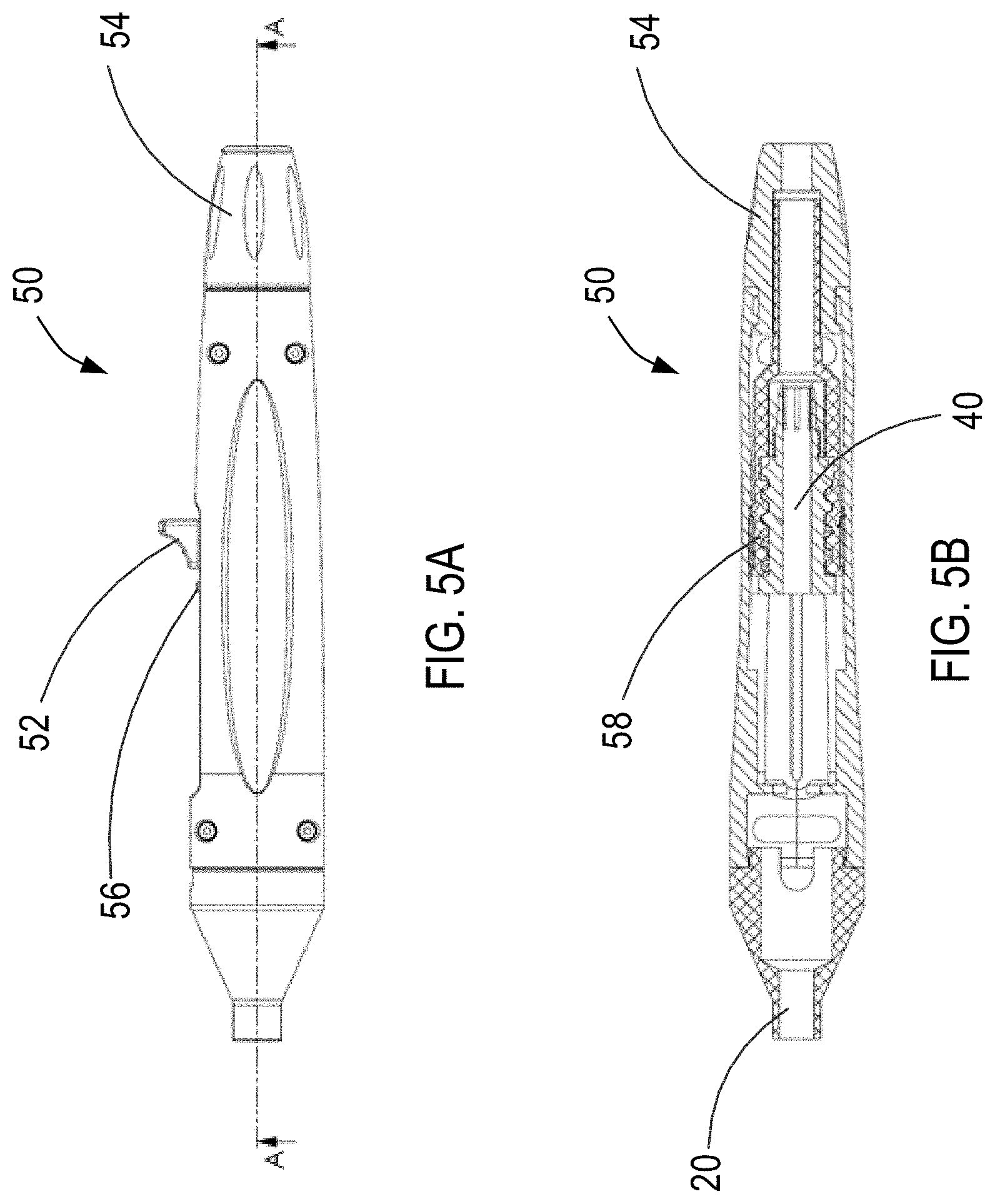
[0045] FIGS. 5A and 5B illustrate an exemplary handle of the device of FIG. 1 constructed in accordance with the principles of the present invention.
[0046] FIG. 6 is a flow chart of exemplary method steps for precise control of blood flow across a patient's interatrial septum in accordance with the principles of the present invention.
[0047] FIGS. 7A to 7I illustrate the steps of the exemplary method of FIG. 6 in accordance with the principles of the present invention.
[0048] FIG. 8 illustrates another alternative exemplary sheath constructed in accordance with the principles of the present invention.
[0049] FIG. 9 illustrates another alternative exemplary sheath having two anchors constructed in accordance with the principles of the present invention.
[0050] FIG. 10 illustrates another alternative exemplary sheath having a graded portion constructed in accordance with the principles of the present invention.
DETAILED DESCRIPTION
[0051] Interatrial shunts, such as those manufactured by V-Wave, Ltd. (Caesarea, Israel), may be used to redistribute blood from one cardiac chamber to another to address pathologies such as heart failure, myocardial infarction and pulmonary arterial hypertension (PAH). For example, in patients with PAH, an interatrial shunt permits blood to flow from the right atrium across the interatrial septum to the left atrium to treat acute right ventricular heart failure. A correctly sized shunt will decompress the right ventricle and improve total systemic oxygen delivery, whereas too small a shunt could have minimal benefit, and too large a shunt could diminish systemic oxygen delivery due to too large an admixture of desaturated blood.
[0052] In patients with left ventricular HF, an interatrial shunt permits blood to flow from the left atrium across the interatrial septum to the right atrium to treat acute left ventricular heart failure due to, e.g., worsening of chronic HF or acute decompensation of the LV following an insult such as acute myocardial infarction resulting in severe pump failure or acute mitral valve regurgitation such as occurs with papillary muscle dysfunction or chordal rupture. A correctly sized shunt will decompress the left ventricle and left atrium and relieve pulmonary congestion without creating RV volume overload, whereas too small a shunt could have minimal benefit, and too large a shunt could create right-sided volume overload and RV failure.
[0053] In patients with more stable PAH or chronic HF, the information gained about hemodynamic responses during temporary precision shunting can be used to guide the sizing of a permanent interatrial shunt, whether it be by placement of an implantable interatrial device or creation of an iatrogenic atrial septal defect.
[0054] Referring now to FIG. 1A, exemplary sheath-shunt prototype device, e.g., device 10, for temporary precision shunting is provided. Device 10 includes proximal region 12 and distal region 14 sized and shaped to be delivered within a patient, e.g., between two heart chambers such as the left and right atrium. Device 10 includes sheath 20 and inner sleeve 40 moveably disposed within a lumen of sheath 20. Sheath 20 may include anchor 30 for fixing sheath 20 relative to the patient's interatrial septum during operation of device 10 as described in further detail below.
[0055] Sheath 20 and inner sleeve 40 extend from distal region 14 of device 10 to proximal region 12 where sheath 20 and inner sleeve 40 are operatively coupled to actuator 50, external to the patient's body. Actuator 50, e.g., a handle, may be selectively actuated to incrementally move inner sleeve 40 relative to sheath 20 to precisely control the amount and rate of blood flow permitted to flow through sheath 20 from one heart chamber to the other depending on the pressure gradient across the interatrial septum. Accordingly, device 10 may simulate blood flow corresponding to the blood flow through interatrial shunts of various sizes. The patient's hemodynamics responsive to the various size shunt simulations may be monitored to determine the most effective shunt size for a specific patient. For example, the correlation between the flowrates measured in-vivo through device 10 and the corresponding flowrates through the interatrial shunts of various sizes may be based on a series of in-vitro comparative simulations under various pressure gradients. In addition, the correlation may be represented in a lookup table and/or stored in a memory of an external controller.
[0056] For example, as shown in FIG. 1B, device 10 further may include one or more sensors 21 coupled to sheath 20, e.g., disposed within the lumen of sheath 20, for measuring one or more physiological parameters including at least one of pressure, blood flow rate, blood flow velocity, or oximetry. Sensors 21 generate and transmit signal(s) indicative of the measured physiological parameter(s) to external controller 55 operatively coupled to one or more sensors 21. Controller 55 may store and monitor the patient's hemodynamics based on the measured physiological parameter(s) such that a physician may determine the shunt size best suited for each specific patient. For example, controller 55 may store predetermined thresholds of desired patient hemodynamics in memory of controller 55, such that controller 55 may compare the measured physiological parameter(s) at each simulated shunt size with the predetermined thresholds to determine which shunt size would provide the most desirable results for the patient.
[0057] Referring now to FIG. 2A, exemplary sheath 20 is provided. Sheath 20 may be made of a biocompatible polymer such as Pebax, Nylon, etc., or high-density polyethylene ("HDPE"). Preferably sheath 20 is made of Pebax. Sheath 20 may have a radiopaque marker band for optimal positioning verification during delivery of sheath 20 to, e.g., the patient's interatrial septum. Sheath 20 has proximal region 22 for coupling with actuator 50, and distal region 24 sized and shaped to be positioned within the patient's body, e.g., across a puncture of the patient's interatrial septum. In accordance with one aspect of the present invention, sheath 20 may have a tapered geometry such that proximal region 22 of sheath 20 has an outer diameter that is smaller than the rest of the sheath's length, e.g., distal region 24 of sheath 20. Accordingly, the differentiation in outer diameter size along sheath 20 may minimize trauma to the access site, and potentially allow longer catheter dwell time. Alternatively, sheath 20, and accordingly the inner sleeve, may have a constant diameter from proximal region 22 to distal region 24.
[0058] As illustrated in FIG. 2A, sheath 20 has a first set of one or more openings 26 at its distal end, and a second set of pre-cut features, e.g., one or more openings 28 disposed along sheath 20 at a position proximal to the first set of one or more openings 26. The second set of one or more openings 28 is positioned a distance from the first set of one or more openings 26 greater than a thickness of the interatrial septum such that while one or more openings 26 is disposed in, e.g., a first atrium, one or more openings 28 are disposed in, e.g., a second atrium. For example, one or more openings 26 may be disposed within the patient's left atrium while one or more openings 28 are disposed within the patient's right atrium, or vice versa. One or more openings 28 are in fluid communication with one or more openings 26 of sheath 20 via a lumen of sheath 20, thereby permitting blood to flow between the patient's right and left atria responsive to a pressure gradient across the interatrial septum via one or more openings 26 and 28 when one or more openings 28 are not obstructed as described in further detail below, and the sheath's lumen. For example, in patients with PAH, blood is permitted to flow from the patient's right atrium, through an opening of one or more openings 28 into the sheath's lumen, and exit through one or more openings 26; whereas in patients with left ventricular HF, blood is permitted to flow from the patient's left atrium, through one or more openings 26 into the sheath's lumen, and exit through an opening of one or more openings 28.
[0059] In another embodiment, the sheath may be manufactured from a polymer which enables its radial expansion subject to balloon inflation, thereby enabling an increase of shunted blood flow. Accordingly, the sheath may be further adjustable via subsequent inflation/deflation of the sheath. Further, sheath 20 may be delivered via the right femoral vein over a guidewire following traditional standard transseptal catheterization. Alternatively, sheath 20 may be delivered via a venous access site once a guidewire pathway to the left atrium has been established by other means.
[0060] As illustrated in FIG. 2A, sheath 20 may include anchor 30, e.g., a septal fixation element, for anchoring sheath 20 relative to, e.g., the patient's interatrial septum, during operation of device 10 to stabilize sheath 20 during retraction of inner sleeve 40. For example, anchor 30 may be an inflatable balloon mounted on the outer surface of sheath 20 at distal region 24. Balloon 30 may have a waist section, for self-registration on the interatrial septum. Balloon 30 may be inflated via an inflation lumen of sheath 20 in fluid communication with the internal space of the balloon and a fluid inflation source. Balloon 30 enables fixation of sheath 20 at the target site, as well as ensures optimal positioning of sheath 20 with respect to the interatrial septum, e.g., one or more openings 26 are located in the mid-LA and one or more openings 28 are located in mid-RA. Balloon 30 may be inflated such that it is disposed on one side of the interatrial septum, or alternatively, on both sides of the interatrial septum such that the balloon sandwiches the interatrial septum for improved fixation as described in further detail below with regard to FIG. 9. For example, when balloon 30 is inflated such that balloon 30 is positioned entirely within the patient's right atrium, sheath 20 will be prevented from moving distally toward the patient's left atrium. Alternatively, when balloon 30 is inflated such that balloon 30 is positioned entirely within the patient's left atrium, sheath 20 will be prevented from moving proximally toward the patient's right atrium. As will be understood by a person having ordinary skill in the art, balloon 30 may be sized and shaped accordingly to anchor sheath 20 within the puncture of the interatrial septum.
[0061] In accordance with another aspect of the present invention, anchor 30 may include a series of septal fixation elements such as deployable tines designed to be delivered to the interatrial septum in a contracted delivery state, and expanded, e.g., upon retracted of an introductory sheath, to an expanded, deployed state to anchor sheath 20 to the interatrial septum. Other septal fixation elements may be affixed to the distal region of sheath 20 to anchor sheath 20 to the interatrial septum including, for example, the septal fixation elements described in U.S. Pat. Nos. 9,943,670, 8,328,751, and 8,091,556 to Keren, U.S. Pat. Nos. 9,724,499 and 8,070,708 to Rottenberg, and U.S. Pat. No. 9,681,948 to Levi, the entire contents of each of which are incorporated herein by reference.
[0062] In accordance with one aspect of the present invention, sheath 20 may have metal coil 31 capable of transmitting RF energy disposed on its external surface, for ablating the contour of the puncture within the patient's fossa ovalis. As shown in FIG. 2A, coil 31 may be disposed on the outer surface of balloon 30, thereby forming a hot balloon such as those described in, e.g., U.S. Pat. No. 5,578,008 to Hara and U.S. Patent Application No. 2010/0069836 to Satake, the entire contents of each of which are incorporated by reference herein. Accordingly, balloon 30 may be used to heat the tissue contouring the puncture within the interatrial septum to ablate the tissue to alter tissue healing to prevent or limit proliferate tissue ingrowth in response to mechanical injury.
[0063] Referring now to FIG. 2B, an alternative exemplary sheath is provided. Sheath 20' is constructed similarly to sheath 20 of FIG. 2A wherein like components are identified by like-primed reference numbers. For example, proximal region 22' corresponds with proximal region 22, distal region 24' corresponds with distal region 24, one or more openings 26' correspond with one or more openings 26, and one or more openings 28' correspond with one or more openings 28. Sheath 20' differs from sheath 20 in that sheath 20' does not include optional anchor 30 disposed on distal region 24'. As will be understood by a person of ordinary skill in the art, the sheath, and accordingly the inner sleeve, may have a constant diameter from the proximal region to the distal region.
[0064] Referring now to FIGS. 3A to 3D, various configurations of the pre-cut features of the second set of one or more openings of the sheath are provided. One or more openings 28, 28' may have a shape selected from oval, circular, rectangular, etc., adapted to provide minimal resistance to flow, i.e., low shear stress and low turbulence, and controlled flowrate by enabling gradual exposure of the one or more openings subject to actuation of actuator 50 as described in further detail below. The disposition and arrangement of the one or more openings may be selected to optimize flow, as well as to maintain structural integrity and functionality of the sheath. The one or more openings may be manufactured using laser-cutting, mechanical puncturing, etc. In accordance with some aspects of the present invention, the one or more openings may include a mesh, e.g., made of a very thin braid of nitinol wires, to prevent passage of emboli therethrough.
[0065] As shown in FIG. 3A, one or more openings 32 have an oval shape and are distributed along the distal region of the sheath in a coil-like pattern such that at least one opening of the one or more openings is positioned more proximal than another one of the one or more openings. As shown in FIG. 3B, one or more openings 34 may have a circular shape, and as shown in FIG. 3C, one or more openings 36 may have a rectangular shape. As shown in FIG. 3C, one or more openings 36 may be distributed equally along a single plane perpendicular to the longitudinal axis of the sheath. The openings may be distributed symmetrically or asymmetrically about the outer surface of sheath 20. As shown in FIG. 3D, the sheath includes four longitudinal openings 38 (two openings not shown) evenly spaced around the circumference of the sheath As will be understood by a person having ordinary skill in the art, more or less openings may be formed along the distal region of the sheath than as shown in FIGS. 3A to 3D.
[0066] Referring now to FIGS. 4A and 4B, exemplary inner sleeve 40 is provided. Inner sleeve 40 may be made of a biocompatible polymer such as Pebax, Nylon, etc., or high-density polyethylene ("HDPE"). Preferably inner sleeve 40 is made of Pebax. In addition, inner sleeve 40 may have a stiffness sufficient to maintain the puncture within the interatrial septum when disposed within sheath 20 across the interatrial septum. Inner sleeve 40 may have a radiopaque marker band for optimal positioning verification when positioning inner sleeve 40 within the lumen of sheath 20. Inner sleeve 40 has proximal region 42 for coupling with actuator 50, and distal region 44 sized and shaped to be moveably disposed within the lumen of sheath 20.
[0067] As shown in FIGS. 4A and 4B, inner sleeve 40 may have one or more flushing ports 46 disposed at distal region 44, and in fluid communication with a flushing fluid source external to the patient's body. Accordingly, flushing fluid may be ejected via one or more flushing ports 46 during operation of device 10 to prevent accumulation of blood clots at one or more openings 26 and/or one or more openings 28 of sheath 20. In addition, inner sleeve 40 may have guidewire lumen 47 for receiving a guidewire therein during delivery of inner sleeve 40 within sheath 20.
[0068] Inner sleeve 40 may have a tapered geometry corresponding with sheath 20 as described above. Accordingly, when both the sheath and inner sleeve have corresponding tapered geometries, as illustrated in FIG. 2C, sheath 20'' may include one or more vents 29, e.g., one or more openings, adjacent to the tapered section along sheath 20'' to permit the displacement of fluid into or out of the changing volume between the two tapered tubes sheath 20'' and inner sleeve 40'. In addition, as illustrated in FIG. 4A, inner sleeve 40 may include one or more flushing vents 45, e.g., one or more openings, positioned on the proximal portion of the tapered section along inner sleeve 40 and in fluid communication with a flushing fluid source external to the patient's body. Accordingly, flushing fluid, e.g., heparinized saline, may be ejected via one or more flushing vents 45 during operation of device 10 to prevent accumulation of thrombus at one or more vents 29 of sheath 20''. Alternatively, in the embodiment where the sheath has a constant diameter from the proximal region to the distal region as described above, inner sleeve 40 also may have a constant diameter from proximal region 42 to distal region 44.
[0069] By comparing FIG. 2C with FIG. 4A, one or more flushing vents 45 may be positioned circumferentially about inner sleeve 40 such that one or more flushing vents 45 are opposite circumferentially to one or more vents 29 of sheath 20'' to allow for more complete flushing of the space between inner sleeve 40 and sheath 20''. Accordingly, one or more vents 29 and one or more flushing vents 45 will allow flow between one or more flushing ports 46 at the distal tip of inner sleeve 40 and one or more flushing vents 45. One or more vents 29 and one or more flushing vents 45 may have a smaller opening area than one or more openings 28'' and may present a small constant baseline flow between the first and second atria, such that the baseline flow may be included in the calibration of device 10.
[0070] Referring again to FIGS. 4A and 4B, at least distal region 44 of inner sleeve 40 may have an outer diameter that is essentially equal to the diameter of the inner surface of the lumen of at least distal region 24 of sheath 20 such that blood may not flow between the outer surface of inner sleeve 40 and the inner surface of sheath 20. Accordingly, when inner sleeve 40 is positioned within the lumen of sheath 20 adjacent to one or more openings 28, the opening of one or more openings 28 is obstructed and blood is not permitted to enter via one or more openings 28. Further, as inner sleeve is moved proximally relative to sheath 20 via actuator 50, the area of the opening of one or more openings 28 increases incrementally from complete obstruction to complete exposure. Thus, the area of the opening of one or more openings 28 may be precisely selected to permit blood to flow between the first and second atria responsive to a pressure gradient across the interatrial septum via the area of the opening of one or more openings 28, one or more openings 26, and the lumen of sheath 20 at a predetermined blood flow rate. Moreover, the selected area of the opening of one or more openings 28 corresponds with a specifically sized shunt, e.g., an interatrial shunt having a diameter at the passageway of the neck region of the shunt equal to, for example, 4 mm, 4.5 mm, 5 mm, 5.5 mm, 6 mm, 6.5 mm, 7 mm, 7.5 mm, or 8 mm. For simulating blood flow through larger interatrial shunts, e.g., having a diameter of greater than 7 mm, variations of the handle engagement may be used for larger diameter correlations. As will be understood by a person having ordinary skill in the art, the selected area of the opening of the one or more openings of the sheath may correspond to a diameter at the passageway of the neck region of the shunt, and is not limited to 0.5 mm increments.
[0071] Referring now to FIG. 4C, an alternative exemplary inner sleeve is provided. Inner sleeve 40' is constructed similarly to inner sleeve 40 of FIG. 4A wherein like components are identified by like-primed reference numbers. For example, proximal region 42' corresponds with proximal region 42, and distal region 44' corresponds with distal region 44. Inner sleeve 40' differs from inner sleeve 40 in that inner sleeve 40' has a first set of one or more apertures 48 at its distal end, and a second set of pre-cut features, e.g., one or more apertures 49 disposed along inner sleeve 40' at a position proximal to one or more apertures 48.
[0072] One or more apertures 49 are in fluid communication with one or more apertures 48 of inner sleeve 40' via a lumen of inner sleeve 40', and one or more apertures 48 is in fluid communication with one or more openings 26 of sheath 20 when inner sleeve 40' is positioned within the lumen of sheath 20, thereby permitting blood to flow between the first and second atria responsive to the pressure gradient across the interatrial septum via an opening between one or more openings 28 and one or more apertures 49, one or more openings 26, one or more apertures 48, and the inner sleeve's lumen and the sheath's lumen, depending on the amount of registration between one or more openings 28 and one or more apertures 49.
[0073] One or more apertures 49 are sized and shaped to register with one or more openings 28 of sheath 20. For example, inner sleeve 40' initially may be positioned within sheath 20 such that one or more apertures 49 and one or more openings 28 are not registered at all, thereby preventing blood from flowing through the opening of one or more openings 28 of sheath 20 as one or more openings 28 are completely obstructed by the body of inner sleeve 40'. Further, as inner sleeve 40' is moved proximally relative to sheath 20, the area of the opening between the lumen of inner sleeve 40' and the RA increases as one or more apertures 49 begin to register with one or more openings 28. As will be understood by a person having ordinary skill in the art, the direction of motion of inner sleeve 40' relative to sheath 20 required to register one or more openings 28 and one or more apertures 49 depends on the location of one or more openings 28 relative to one or more apertures 49. For example, if one or more openings 28 are positioned distal to one or more apertures 49 in the operation position, distal movement of inner sleeve 40' will permit registration of one or more openings 28 and one or more apertures 49.
[0074] Accordingly, blood is permitted to flow between the first and second atria responsive to a pressure gradient across the interatrial septum via the opening of one or more openings 28 created by the registration between one or more openings 28 and one or more apertures 49, one or more openings 26 of sheath 20, one or more apertures 48 of inner sleeve 40', and the lumens of sheath 20 and inner sleeve 40'. Inner sleeve 40' may be moved incrementally such that each selected position of inner sleeve 40' with respect to sheath 20 provides a predetermined area of the opening of one or more openings 28 corresponding with a specific interatrial shunt size. When one or more apertures 49 are completely registered with one or more openings 28, device 10 simulates blood flow through a maximum sized shunt, e.g., 8 mm.
[0075] Referring now to FIGS. 5A and 5B, an exemplary actuator is provided. Actuator 50 may be a handle sized and shaped to be easily controlled by the physician external to the patient's body, and includes very accurate mechanisms to control retraction or advancement of inner sleeve 40 within sheath 20. Actuator 50 is operatively coupled to the proximal regions of sheath 20 and inner sleeve 40 such that actuation of actuator 50 incrementally moves distal region 44 of inner sleeve 40 relative to distal region 24 of sheath 20. Shunted blood volume may be translated to effective shunt diameter by pre-set features on actuator 50. As shown in FIG. 5A, actuator 50 may include first actuator 52, e.g., a switch, and second actuator 54, e.g., a rotatable knob. First actuator 52 is operatively coupled to inner sleeve 40 such that actuation of first actuator 52, e.g., retraction of first actuator 52 relative to actuator 50, causes inner sleeve 40 to move a predetermined distance relative to sheath 20. For example, in the initial starting position, first actuator 52 is positioned at a distal portion of actuator 50 and serves as a dilator within sheath 20. Accordingly, inner sleeve 40 is positioned within sheath 20 such that blood is not permitted to flow through one or more openings 28 of sheath 20 due to obstruction of the opening of one or more openings 28 by inner sleeve 40.
[0076] First actuator 52 may then be moveable to a second operation position proximal to the initial starting position along actuator 50, thereby causing inner sleeve 40 to move a predetermined distance relative to sheath 20. In the second operation position, the distal end of inner sleeve 40 is positioned adjacent to one or more openings 28 of sheath 20, though not exposing any opening of one or more openings 28, and thus preventing blood to flow therethrough. Accordingly, upon actuation of first actuator 52, device 10 is ready to use. In addition, actuator 50 may include marker 56 for providing a visual indication to the physician of the current simulated shunt size.
[0077] Referring now to FIG. 5B, a cross-sectional view of actuator 50 along line A-A of FIG. 5A is illustrated. As shown in FIG. 5B, second actuator 54 may have threaded portion 58 corresponding to a threaded portion of actuator 50 such that rotation of second actuator 54 precisely and gradually moves inner sleeve 40 relative to sheath 20. Accordingly, the length of sheath 20 may be fixed relative to actuator 50, whereas the inner sleeve 40 moves proximally or distally relative to sheath 20 via actuation of second actuator 54 to expose or block one or more openings 28 of sheath 20. For example, after first actuator 52 is moved from the initial starting position to the second operation position, second actuator 54 may then be actuated to incrementally and gradually move inner sleeve 40 relative to sheath 20, thereby incrementally increasing the area of the opening of one or more openings 28 of sheath 28 to permit blood to flow therethrough.
[0078] Referring now to FIG. 6, the steps of exemplary method 60 of using device 10 of FIG. 1A for precise control of blood flow across a patient's interatrial septum in accordance with the principles of the present invention are provided. Some of the steps of method 60 may be further elaborated by referring to FIGS. 7A-7I. In addition, for purposes of discussion below, method 60 will be described for precise control of blood flow from the patient's right atrium, across the interatrial septum to the patient's left atrium, e.g., to treat PAH; however, as will be understood by a person having ordinary skill in the art, method 60 may be used for precise control of blood flow from the patient's left atrium, across the interatrial septum to the patient's right atrium, e.g., to treat LVHF, depending on the pressure gradient across the interatrial septum. Moreover, method 60 may be used to facilitate blood flow from one heart chamber to another heart chamber.
[0079] At step 61, a puncture is created through the patient's interatrial septum, e.g., through the patient's fossa ovalis, using techniques known in the art such as those described in U.S. Pat. No. 9,713,696 to Yacoby, the entire contents of which is incorporated by reference herein. Accordingly, a guidewire may be delivered across the puncture of the interatrial septum, and at step 62, sheath 20 is delivered over the guidewire and across the puncture of the interatrial septum such that one or more openings 26 are disposed within a first atrium, e.g., the left atrium, and one or more openings 28 are disposed within the second atrium, e.g., the right atrium, as shown in FIG. 7A. Inner sleeve 40 is disposed within the lumen of sheath 20 such that inner sleeve 40 serves as a dilator, and sheath 20 and inner sleeve 40 are advanced over the guidewire via guidewire lumen 47 of inner sleeve 40. Metal coil 31 may be used to emit RF energy to heat the tissue contouring the puncture of the interatrial septum, to thereby ablate the tissue and alter tissue healing to prevent or limit proliferate tissue in growth in response to mechanical injury.
[0080] At step 63, sheath 20 may optionally be anchored to the interatrial septum, such as by inflating balloon 30 within the left atrium, thereby preventing proximal movement of sheath 20 with respect to the patient's interatrial septum, as shown in FIG. 7B. As described above, different shaped balloons may be used to secure sheath 20 within the puncture of the interatrial septum. For example, the balloon may have a dog-bone shape such that the waist of the balloon contacts the contour of the puncture of the interatrial septum while the opposing sides of the balloon are inflated to sandwich the interatrial septum therebetween. Accordingly, metal coil 31 may be disposed on the waist of the balloon, and actuated to emit RF energy to ablate the surrounding tissue to alter tissue healing adjacent the waist of the balloon. When sheath 20' is used, step 63 may be skipped and/or other means of anchoring the sheath may be deployed. In addition, as described above, alternative or additional septal fixation elements, e.g., deployable tines, may be used to anchor sheath 20 to the interatrial septum.
[0081] At step 64, actuator 50 is actuated to move inner sleeve 40 proximally within sheath 20 to modify the area of the opening of one or more openings 28 of sheath 20. For example, as shown in FIG. 7C, first actuator 52 may be moved from the initial starting position proximally to the second operation position. When first actuator 52 is in the second operation position, second actuator 54 may then be actuated to incrementally move inner sleeve 40 with respect to sheath 20 as shown in FIG. 7D. Specifically, FIG. 7D illustrates when second actuator 54 has been rotated such that marker 56 moves from an initial position indicating complete obstruction of one or more openings 28 and thus, no blood flows from the right atrium through one or more openings 28 into the left atrium, to a position along actuator 50 indicating the minimum opening of one or more openings 28 to permit blood flow therethrough corresponding to, e.g., a 4 mm interatrial shunt. In addition, first actuator 52 may also function as a safety lock such that second actuator 54 may not be actuated until first actuator 52 is actuated to the second operation position.
[0082] Accordingly, second actuator 54 may then be actuated to incrementally move inner sleeve 40 relative to sheath 20 as illustrated in FIGS. 7E to 7G. For example, as shown in FIG. 7E, second actuator 54 may be rotated until marker 56 indicates that the area of the opening of one or more openings 28 permits blood to flow therethrough between the right and left atria at a blood flow rate corresponding with blood flow through a 4.5 mm interatrial shunt. As shown in FIG. 7F, second actuator 54 may be further rotated until marker 56 indicates that the area of the opening of one or more openings 28 permits blood to flow therethrough between the right and left atria at a blood flow rate corresponding with blood flow through a 5 mm interatrial shunt. As shown in FIG. 7G, second actuator 54 may further be rotated until marker 56 indicates that the area of the opening of one or more openings 28 permits blood to flow therethrough between the right and left atria at a blood flow rate corresponding with blood flow through a 5.5 mm interatrial shunt. As will be understood by a person having ordinary skill in the art, actuator 50 may be actuated to simulate blood flow through smaller or larger interatrial shunts, e.g., a 3.5 mm shunt, a 6 mm shunt, a 6.5 mm shunt, a 7 mm shunt, a 7.5 mm shunt, and an 8 mm shunt, etc.
[0083] As described above, the area of the opening of one or more openings 28 may be measured as the space between one or more openings 28 and the body of inner sleeve 40, or the registered space between one or more openings 28 of sheath 20 and one or more apertures 49 of inner sleeve 40'. In addition, the decision of which sized shunt to select for the patient may be based on a conversion lookup table derived from comparative in vitro bench tests or in-vivo experiments.
[0084] Moreover, at step 65, the patient's hemodynamics may be monitored by measuring the patient's physiological parameters at each incremental area of the opening of one or more openings 28 during operation of device 10. For example, one or more sensors 21 may measure one or more physiological parameters including at least one of pressure, blood flow rate, blood flow velocity, or oximetry, to determine to effectiveness of the therapy, e.g., on interatrial pressures, cardiac output, blood saturation, etc. Sensors 21 may further generate a signal(s) indicative of the measured physiological parameters for transmission to external controller 55 for monitoring. Alternatively, or additionally, the guidewire used to deliver sheath 20 and inner sleeve 40 may be a pressure sensor guidewire operatively coupled to external controller 55 for measuring pressure within the first atrium and generating a signal indicative of the measured pressure for transmission to external controller 55. Accordingly, external controller 55 may compare the measured physiological parameters with stored desired threshold values and display such results such that a physician may determine which sized shunt is best suited for each individual patient.
[0085] At step 66, the physician selects a specifically sized interatrial shunt to be implanted within the puncture of the specific patient's interatrial septum based on the patient's monitored hemodynamics responsive to each actuated increment of actuator 50. For example, as shown in FIG. 7H, the physician may select between shunt 70 having a 5 mm diameter at neck region 76 between first region 72 and second region 74, shunt 80 having a 5.5 mm diameter at neck region 86 between first region 82 and second region 84, and shunt 90 having a 6 mm diameter at neck region 96 between first region 92 and second region 94 for implantation within the patient. As will be understood by a person having ordinary skill in the art, smaller or larger interatrial shunts may be selected for implantation including, e.g., a 4.5 mm shunt, a 6.5 mm shunt, a 7 mm shunt, a 7.5 mm shunt, or an 8 mm shunt. Accordingly, the selected interatrial shunt, e.g., shunt 70, may then be implanted within the patient's interatrial septum AS, as shown in FIG. 7I, via methods and delivery tools as described in, e.g., U.S. Pat. No. 8,091,556 to Keren, U.S. Pat. No. 9,713,696 to Yacoby, U.S. Pat. No. 10,076,403 Eigler, the entire contents of each of which are incorporated by reference herein. Alternatively, sheath 20 and inner sleeve 40 may be detached from actuator 50 and kept in the patient's body for a period of time, as may be required, until removal.
Experimental Results
[0086] The testing described in this section was conducted on an hourglass-shaped interatrial shunt (manufactured by V-Wave, Ltd, Caesarea, Israel), and a sheath-shunt prototype device under Steady Forward Flow test conditions. The purpose of this test was to compare the flow rates passing through 5 mm and 6 mm interatrial shunts and demonstrate how these correlate with flow rates passing through two corresponding settings on the actuator of the sheath-shunt prototype device. As demonstrated Table 2 below, there is good correlation between the two, with deviations ranging from 1% to 10% in maximum at various interatrial pressure gradient conditions.
TABLE-US-00002 TABLE 2 Flow [ml/min] Flow [ml/min] .DELTA.P [mm 5 mm Error 6 mm Error Hg] Shunt Sheath [%] Shunt Sheath [%] 6 1212 1316 8.5 1600 1621 1.3 1287 1330 3.3 1717 1753 2.1 8 1360 1430 5.1 1910 1851 3.1 1395 1445 3.5 1959 1911 2.4 10 1525 1682 10.2 2100 2045 2.6 1554 1692 8.8 2170 2135 1.6 12 1765 1844 4.4 2269 2198 3.1 1790 1879 4.9 2328 2277 2.1
[0087] In accordance with another aspect of the present invention, the sheath may include three sets of one or more openings as shown in FIG. 8.
[0088] Sheath 20''' of FIG. 8 is constructed similarly to sheath 20 of FIG. 2A wherein like components are identified by like-triple primed reference numbers. For example, proximal region 22''' corresponds with proximal region 22, distal region 24''' corresponds with distal region 24, one or more openings 26''' corresponds with one or more openings 26, and one or more openings 28''' correspond with one or more openings 28. Sheath 20''' differs from sheath 20 in that sheath 20''' includes third set of one or more openings 33.
[0089] Third set of one or more openings 33 may be positioned on sheath 20''' at a location spaced apart from first and second set of one or more openings 26''', 28''' such that when second set of one or more openings 28''' is disposed within the right atrium, third set of one or more openings 33 is disposed within the inferior vena cava above the patient's renal veins. Accordingly, upon further retraction of the inner sleeve, third set of one or more openings 33 may be exposed while second set of one or more openings 28''' are blocked, thereby permitting blood to flow via third set of one or more openings 33 and not second set of one or more openings 28''' responsive to the pressure gradient between the inferior vena cava and the left atrium. This may be accomplished by using an inner sleeve constructed similar to inner sleeve 40' having a first set of one or more apertures in fluid communication with first set of one or more openings 26''' of sheath 20''', a second set of one or more apertures sized and shaped to register with the sheath's second set of one or more openings 28''', and a third set of one or more apertures sized and shaped to register with the sheath's third set of one or more openings 33.
[0090] For example, when second set of one or more openings 28''' of sheath 20''' completely register with the second set of one or more apertures of the inner sleeve, third set of one or more openings 33 of sheath 20''' do not register at all with the third set of one or more apertures of the inner sleeve, and when second set of one or more openings 28''' of the sheath do not register at all with the first set of one or more apertures of the inner sleeve, third set of one or more openings 33 of the sheath 20''' registers with the third set of one or more apertures of the inner sleeve.
[0091] The second and third set of one or more apertures of the inner sleeve may be spaced apart a sufficient distance such that blood enters only via second set of one or more openings 28''' or third set of one or more openings 33 of sheath 20''' at a time. Since the venous return from the inferior vena cava is relatively enriched with oxygen because of less oxygen extraction by the kidneys, this source of shunted blood will cause a smaller fall in systemic oxygen saturation than a similarly sized shunt originating from the second set of one or more openings. This may be more advantageous for treating acute RV decompensation.
[0092] Referring now to FIG. 9, an alternative exemplary sheath having dual anchors is provided. Sheath 20'''' is constructed similarly to sheath 20 of FIG. 2A wherein like components are identified by like-quadruple primed reference numbers. For example, proximal region 22'' corresponds with proximal region 22, distal region 24'' corresponds with distal region 24, one or more openings 26'' correspond with one or more openings 26, one or more openings 28'' correspond with one or more openings 28, and balloon 30'''' corresponds with balloon 30. Sheath 20'''' differs from sheath 20 in that sheath 20'''' includes second balloon 35 disposed on distal region 24'''' of sheath 20'''' proximal to balloon 30''''. Accordingly, balloon 35 may be inflated such that balloon 35 is positioned entirely within the patient's right atrium, and balloon 30'''' may be inflated such that balloon 30'''' is positioned entirely within the patient's left atrium, and thus, inflated balloons 30'''' and 35 may sandwich the interatrial septum for improved fixation, preventing both proximal and distal movement relative to the atrial septum. As will be understood by a person of ordinary skill in the art, like balloon 30 of FIG. 2A, balloon 30'''' and/or balloon 35 may have metal coils disposed thereon.
[0093] Referring now to FIG. 10, another alternative exemplary sheath having a graded portion is provided. Sheath 100 is constructed similarly to sheath 20' of FIG. 2B. For example, proximal region 102 corresponds with proximal region 22', distal region 104 corresponds with distal region 24', one or more openings 106 correspond with one or more openings 26', and one or more openings 108 correspond with one or more openings 28'. Sheath 100 differs from sheath 20' in that sheath 100 has graded portion 110 in the vicinity of distal region 104. As shown in FIG. 10, graded portion 110 may be positioned at a predetermined distance proximal to one or more openings 108, e.g., 1-4 cm, such that when graded portion 110 is disposed in the puncture of the interatrial septum, distal region 104 of sheath 100 does not extend too far within the left atrium.
[0094] Moreover, one or more metal coils, e.g., metal coils 112, 114, and 116, may be disposed on the outer surface of graded portion 110 of sheath 100 at preselected positions along graded portion 110 corresponding with predetermined interatrial shunt sizes. For example, the cross-sectional area of sheath 100 at graded portion 110 may decrease in the direction from distal region 104 toward proximal region 102, and metal coil 112 may be positioned on graded portion 110 corresponding with, e.g., a 5 mm diameter interatrial shunt, metal coil 114 may be positioned on graded portion 110 corresponding with, e.g., a 5.5 mm diameter interatrial shunt, and metal coil 116 may be positioned on graded portion 110 corresponding with, e.g., a 6 mm diameter interatrial shunt.
[0095] Thus, after the physician determines which sized shunt is best suited for a patient using the systems and methods described herein, sheath 100 may be moved distally through the puncture of the interatrial septum until the interatrial septum aligns within any one of metal coils 112, 114, or 116. Accordingly, the puncture of the interatrial septum conforms to the cross-sectional area of graded portion 110 positioned therethrough, and the respective metal coil may be actuated to emit RF energy to ablate tissue adjacent to the metal coil to induce an interatrial shunt having a size corresponding to the cross-sectional area of graded portion 110. For example, if the interatrial septum is aligned with metal coil 112, ablation of the interatrial tissue surrounding metal coil 112 via metal coil 112 will result in a puncture sized to receive interatrial shunt 70 of FIG. 7H. Similarly, if the interatrial septum is aligned with metal coil 114, ablation of the interatrial tissue surrounding metal coil 114 via metal coil 114 will result in a puncture sized to receive interatrial shunt 80 of FIG. 7H, and if the interatrial septum is aligned with metal coil 116, ablation of the interatrial tissue surrounding metal coil 116 via metal coil 116 will result in a puncture sized to receive interatrial shunt 90 of FIG. 7H. As will be understood by a person having ordinary skill in the art, there may be less or more than three metal coils disposed along the length of graded portion 110, and/or graded portion 110 may have a geometry such that the metal coils disposed thereon induce interatrial shunts of sizes less 5 mm or greater than 6 mm, e.g., 6.5 mm, 7 mm, 7.5 mm, 8 mm, etc. In addition, any of the sheaths described herein, e.g., sheath 20, sheath 20', sheath 20'', sheath 20''', or sheath 20'''', may include a graded portion similar to graded portion 110.
[0096] In one embodiment, instead of graded portion 110, the sheath may have a hot balloon disposed thereon proximal to the one or more openings configured to be disposed in the patient's left atrium, such that after the physician determines which sized shunt is best suited for a patient using the systems and methods described herein, sheath 100 may be moved distally through the puncture of the interatrial septum until the interatrial septum aligns with the metal coils on the hot balloon. The hot balloon may then be inflated to a selected size to thereby expand the puncture of the interatrial septum to a size corresponding with the desired shunt size. The hot balloon may then be actuated to ablate the tissue of the interatrial septum surrounding the hot balloon to induce the desired interatrial shunt, such that the desired interatrial shunt may be implanted within the ablated puncture.
[0097] In accordance with another aspect of the present invention, the sheath may include two sets of one or more openings, e.g., a first set of one or more openings positioned at the distal region of the sheath such that they are positioned within the patient's left atrium, and a second set of one or more openings positioned on the sheath at a location spaced apart from the first set of one or more openings such that when the first set of one or more openings is disposed within the left atrium, the second set of one or more openings is disposed within the inferior vena cava just caudal of the patient's renal veins during operation. Accordingly, an inner sleeve having corresponding first and second sets of one or more apertures may be actuated to modify the area of the opening of the second set of one or more openings of the sheath to permit blood to flow between the inferior vena cava and the left atrium responsive to a pressure gradient between the inferior vena cava and the left atrium in accordance with the principles of the present invention described above. For example, when the sheath is intended to provide right to left flow, as in PAH, there would be a reduced flow compared to the shorter flow path through the sheaths between the RA and LA, which may be accounted for during calibration of the system.
[0098] While various illustrative embodiments of the invention are described above, it will be apparent to one skilled in the art that various changes and modifications may be made herein without departing from the invention. It will further be appreciated that the devices described herein may be implanted in other positions in the heart. For example, device 10 may be similarly used for treating conditions in which the distal chamber (LA) pressure is higher than the proximal chamber (RA) pressure, as occurs in patients with congestive heart failure. In such cases, the flow will be in the direction from the left atrium to the right atrium. There are small, e.g., approximately 10%, differences in calibrated effective flow diameters between forward and reverse flow, which may be allowed for by providing separate calibrations on the actuator. In addition, device 10 may be implanted across the ventricular septum, in an orientation suitable to shunt blood between the left ventricle and the right ventricle, depending on the pressure gradient between the left and right ventricles. The appended claims are intended to cover all such changes and modifications that fall within the true spirit and scope of the invention.
* * * * *
D00000
D00001
D00002
D00003
D00004
D00005
D00006
D00007
D00008
D00009
D00010
D00011
D00012
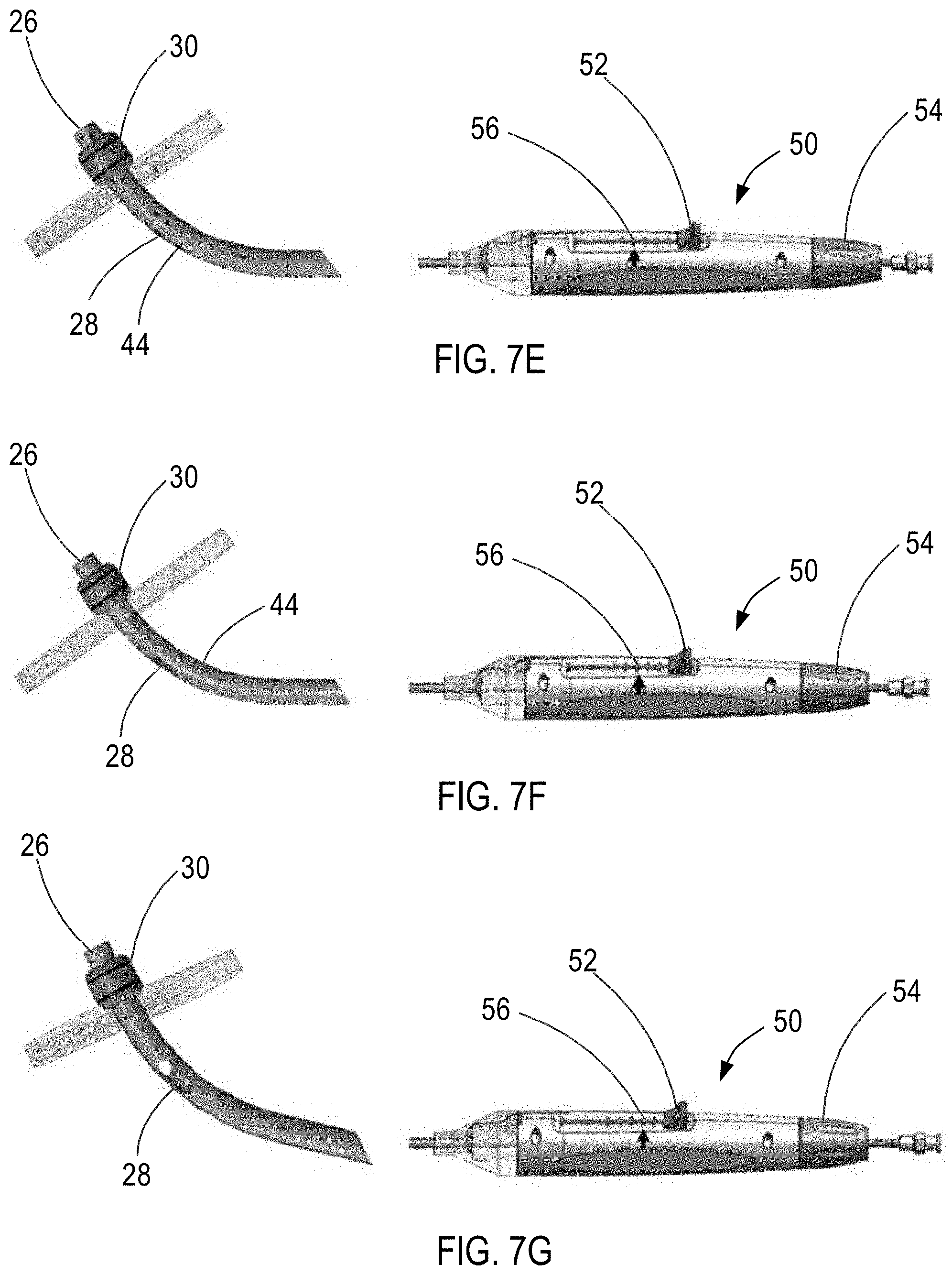
D00013
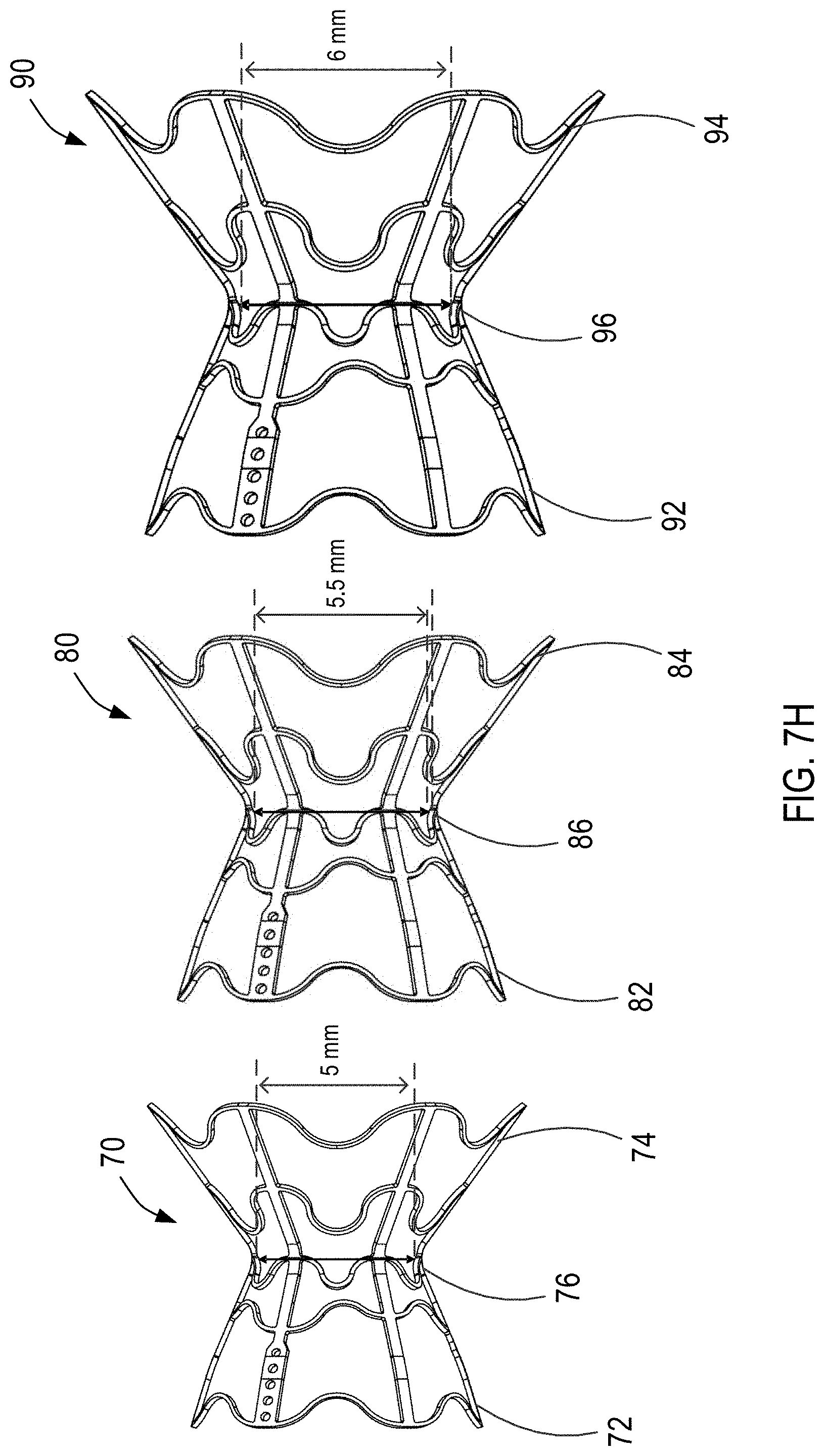
D00014

D00015
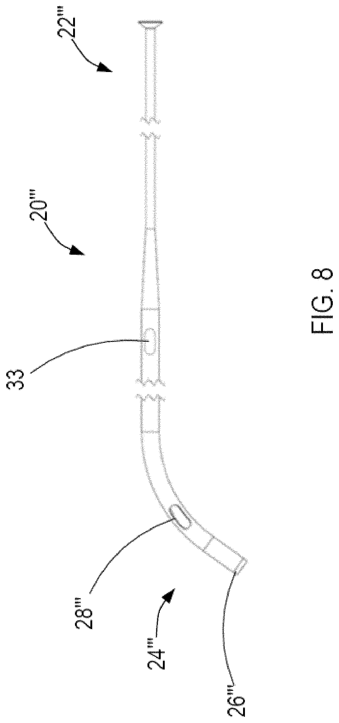
D00016

D00017
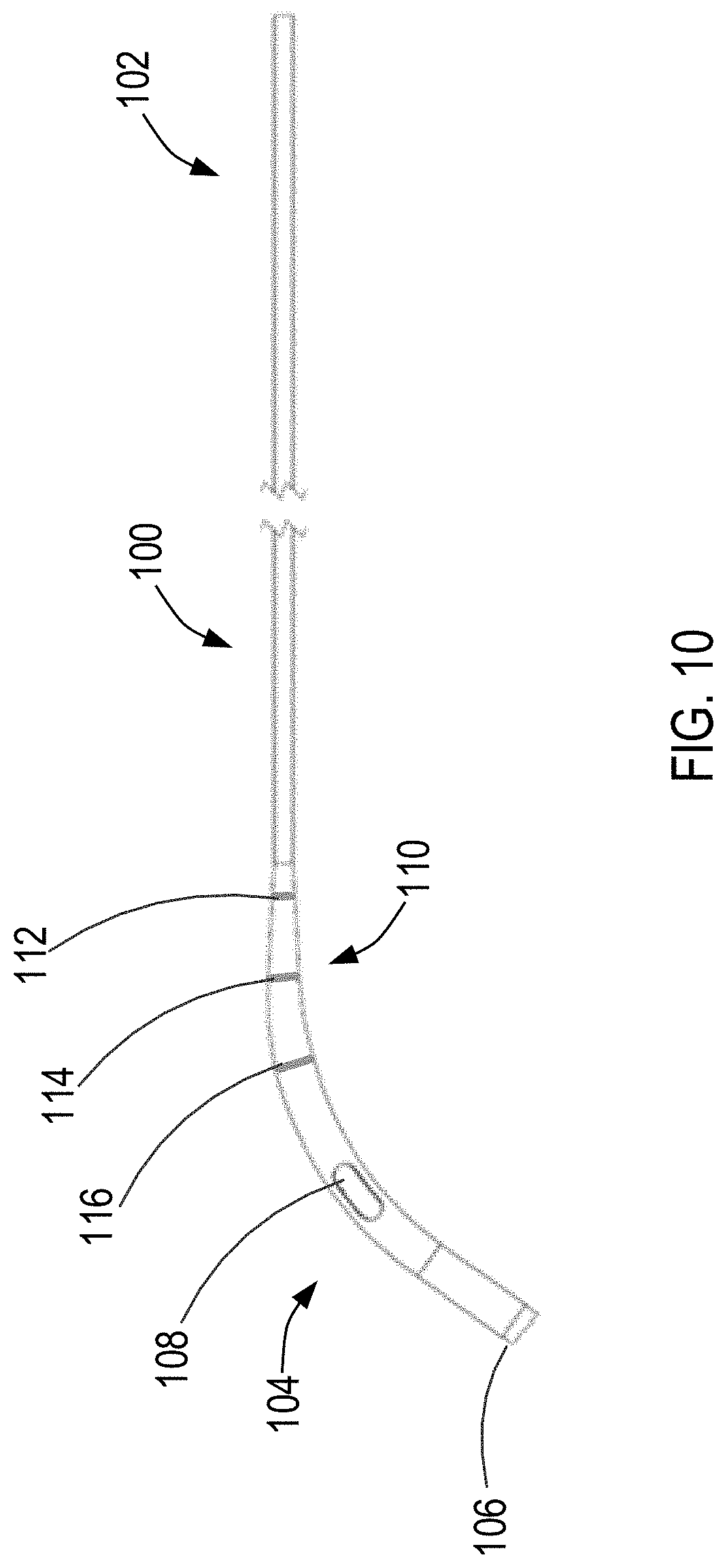
XML
uspto.report is an independent third-party trademark research tool that is not affiliated, endorsed, or sponsored by the United States Patent and Trademark Office (USPTO) or any other governmental organization. The information provided by uspto.report is based on publicly available data at the time of writing and is intended for informational purposes only.
While we strive to provide accurate and up-to-date information, we do not guarantee the accuracy, completeness, reliability, or suitability of the information displayed on this site. The use of this site is at your own risk. Any reliance you place on such information is therefore strictly at your own risk.
All official trademark data, including owner information, should be verified by visiting the official USPTO website at www.uspto.gov. This site is not intended to replace professional legal advice and should not be used as a substitute for consulting with a legal professional who is knowledgeable about trademark law.