Securing Mechanism For A Drawer Slide In A Domestic Home Appliance
Ciampi; Nicholas ; et al.
U.S. patent application number 16/416315 was filed with the patent office on 2020-11-26 for securing mechanism for a drawer slide in a domestic home appliance. The applicant listed for this patent is BSH Hausgerate GmbH, BSH Home Appliances Corporation. Invention is credited to Nicholas Ciampi, William Daniels, Norman Sewell, Troy Wilson.
| Application Number | 20200367648 16/416315 |
| Document ID | / |
| Family ID | 1000004122243 |
| Filed Date | 2020-11-26 |


| United States Patent Application | 20200367648 |
| Kind Code | A1 |
| Ciampi; Nicholas ; et al. | November 26, 2020 |
SECURING MECHANISM FOR A DRAWER SLIDE IN A DOMESTIC HOME APPLIANCE
Abstract
A drawer slide assembly for use with a domestic home appliance having a main body and a drawer. The assembly includes a slide bracket configured to be non-movably attached to the main body, the slide bracket having a first engagement portion; a slide having a first part having a second engagement portion, the first part being attached to the slide bracket by the second engagement portion slidably engaging the first engagement portion, and a second part configured to be non-movably attached to the drawer such that the second part is positionally fixed relative to the drawer; and a slide retainer attached to the slide bracket and preventing the second part of the slide from moving.
| Inventors: | Ciampi; Nicholas; (Cove City, NC) ; Daniels; William; (New Bern, NC) ; Sewell; Norman; (New Bern, NC) ; Wilson; Troy; (Cove City, NC) | ||||||||||
| Applicant: |
|
||||||||||
|---|---|---|---|---|---|---|---|---|---|---|---|
| Family ID: | 1000004122243 | ||||||||||
| Appl. No.: | 16/416315 | ||||||||||
| Filed: | May 20, 2019 |
| Current U.S. Class: | 1/1 |
| Current CPC Class: | F24C 15/18 20130101; A47B 2088/4274 20170101; A47B 88/473 20170101; A47B 88/407 20170101; A47B 88/43 20170101; A47B 88/423 20170101; F24C 15/168 20130101 |
| International Class: | A47B 88/427 20060101 A47B088/427; F24C 15/16 20060101 F24C015/16; A47B 88/483 20060101 A47B088/483; A47B 88/407 20060101 A47B088/407 |
Claims
1. A domestic home appliance, comprising: a main body; a drawer that slides relative to the main body between an open position and a closed position; a slide bracket that is non-movably attached to the main body such that the slide bracket is positionally fixed relative to the main body when the slide bracket is in an operating position, the slide bracket having a first engagement portion; a slide having a first part having a second engagement portion, the first part being attached to the slide bracket by the second engagement portion slidably engaging the first engagement portion as the first part is moved in a first direction relative to slide bracket, and a second part that is non-movably attached to the drawer such that the second part is positionally fixed relative to the drawer when the second part is in an operating position, the second part moving in the first direction relative to the first part as the drawer slides from the closed position to the open position; and a slide retainer attached to the slide bracket and preventing the second part of the slide from moving in a second direction opposite to the first direction.
2. The domestic home appliance of claim 1, wherein the slide retainer is non-destructively removably attached to the slide bracket.
3. The domestic home appliance of claim 1, wherein a back end of the second part of the slide contacts the slide retainer to prevent the second part of the slide from moving in the second direction.
4. The domestic home appliance of claim 3, wherein the slide retainer comprises a plate-like portion, and the back end of the second part of the slide contacts the plate-like portion to prevent the second part of the slide from moving in the second direction.
5. The domestic home appliance of claim 3, further comprising a slide stop at a front end of the second part of the slide, the front end being located opposite the back end.
6. The domestic home appliance of claim 5, wherein contact between the slide stop and the first part of the slide is prevented by the back end of the second part of the slide contacting the slide retainer.
7. The domestic home appliance of claim 5, wherein the slide stop prevents movement in the second direction of the second part of the slide relative to the first part of the slide by the slide stop contacting the first part of the slide.
8. The domestic home appliance of claim 7, wherein the slide stop contacts the first part of the slide simultaneously with the back end of the second part of the slide contacting the slide retainer.
9. The domestic home appliance of claim 1, wherein the slide retainer comprises a plate-like portion, and the second part of the slide contacts the plate-like portion to prevent the second part of the slide from moving in the second direction.
10. The domestic home appliance of claim 1, wherein the first part of the slide is removable from the slide bracket by moving the first part of the slide in the second direction relative to the slide bracket when the slide retainer is detached from the slide bracket.
11. The domestic home appliance of claim 1, further comprising a second one of the slide.
12. A drawer slide assembly for use with a domestic home appliance having a main body and a drawer that slides relative to the main body between an open position and a closed position, the assembly comprising: a slide bracket configured to be non-movably attached to the main body such that the slide bracket is positionally fixed relative to the main body when the slide bracket is in an operating position, the slide bracket having a first engagement portion; a slide having a first part having a second engagement portion, the first part being attached to the slide bracket by the second engagement portion slidably engaging the first engagement portion as the first part is moved in a first direction relative to slide bracket, and a second part configured to be non-movably attached to the drawer such that the second part is positionally fixed relative to the drawer when the second part is in an operating position, the second part moving in the first direction relative to the first part; and a slide retainer attached to the slide bracket and preventing the second part of the slide from moving in a second direction opposite to the first direction.
13. The drawer slide assembly of claim 12, wherein the slide retainer is non-destructively removably attached to the slide bracket.
14. The drawer slide assembly of claim 12, wherein a back end of the second part of the slide contacts the slide retainer to prevent the second part of the slide from moving in the second direction.
15. The drawer slide assembly of claim 14, wherein the slide retainer comprises a plate-like portion, and the back end of the second part of the slide contacts the plate-like portion to prevent the second part of the slide from moving in the second direction.
16. The drawer slide assembly of claim 14, further comprising a slide stop at a front end of the second part of the slide, the front end being located opposite the back end, wherein the slide stop contacts the first part of the slide simultaneously with the back end of the second part of the slide contacting the slide retainer.
17. The drawer slide assembly of claim 14, further comprising a slide stop at a front end of the second part of the slide, the front end being located opposite the back end, wherein contact between the slide stop and the first part of the slide is prevented by the back end of the second part of the slide contacting the slide retainer.
18. The drawer slide assembly of claim 12, wherein the slide retainer comprises a plate-like portion, and the second part of the slide contacts the plate-like portion to prevent the second part of the slide from moving in the second direction.
19. The drawer slide assembly of claim 12, wherein the first part of the slide is removable from the slide bracket by moving the first part of the slide in the second direction relative to the slide bracket when the slide retainer is unattached to the slide bracket.
20. The drawer slide assembly of claim 12, further comprising a second one of the slide.
Description
FIELD OF THE INVENTION
[0001] The invention is directed to a domestic home appliance. More particularly, embodiments of the invention are directed to a securing mechanism that prevents disassociation of a drawer slide from a slide bracket in a domestic home appliance.
[0002] An example of an application for the invention is a domestic kitchen oven having a drawer that slides between an open position and a closed position.
BACKGROUND OF THE INVENTION
[0003] Some modern domestic kitchens include cooking appliances such as ovens and ranges that have one or more drawers such as, for example, a warming drawer. The drawers are often mounted to the appliances by way of one or more slide mechanisms. The slide mechanisms allow the draw to move in and out of a space in the appliance. The slide mechanisms can become worn and/or their operation can be adversely affected by food or other debris becoming lodged in the mechanisms. As a result, non-destructive removal of the slide mechanisms for cleaning or replacement is advantageous.
[0004] Applicants recognized an improvement to the above arrangement and implement that improvement in embodiments of the invention.
SUMMARY
[0005] The invention achieves the benefit of providing non-destructive removal of the slide mechanisms for cleaning or replacement while also providing secure mounting of the slide of the mechanism to the slide bracket of the mechanism. Some slides are removably attached to the slide bracket by one or more engagement portions on the slide that slidably engage one or more engagement portions on the slide bracket. With this type of attachment, the slide can undesirably detach from the slide bracket during, for example, shipping or due to some other jarring or outside force. For example, a drawer of a domestic home appliance can become dislodged from the main body of the appliance during shipping of the appliance due to the slide detaching from the slide bracket.
[0006] Embodiments of the invention address the above problem by providing a slide retainer on the slide bracket. The slide retainer prevents movement of a portion of the slide relative to the slide bracket, or at least limits movement of a portion of the slide relative to the slide bracket so that the slide cannot detach from the slide bracket.
[0007] Particular embodiments of the invention are directed to a domestic home appliance having a main body; a drawer that slides relative to the main body between an open position and a closed position; a slide bracket that is non-movably attached to the main body such that the slide bracket is positionally fixed relative to the main body when the slide bracket is in an operating position, the slide bracket having a first engagement portion; a slide having a first part having a second engagement portion, the first part being attached to the slide bracket by the second engagement portion slidably engaging the first engagement portion as the first part is moved in a first direction relative to slide bracket, and a second part that is non-movably attached to the drawer such that the second part is positionally fixed relative to the drawer when the second part is in an operating position, the second part moving in the first direction relative to the first part as the drawer slides from the closed position to the open position; and a slide retainer attached to the slide bracket and preventing the second part of the slide from moving in a second direction opposite to the first direction.
[0008] In some embodiments, the slide retainer comprises a plate-like portion, and the second part of the slide contacts the plate-like portion to prevent the second part of the slide from moving in the second direction.
[0009] In some embodiments, the first part of the slide is removable from the slide bracket by moving the first part of the slide in the second direction relative to the slide bracket when the slide retainer is detached from the slide bracket.
[0010] Other embodiments of the invention are directed to a drawer slide assembly for use with a domestic home appliance having a main body and a drawer that slides relative to the main body between an open position and a closed position. The assembly includes a slide bracket configured to be non-movably attached to the main body such that the slide bracket is positionally fixed relative to the main body when the slide bracket is in an operating position, the slide bracket having a first engagement portion; a slide having a first part having a second engagement portion, the first part being attached to the slide bracket by the second engagement portion slidably engaging the first engagement portion as the first part is moved in a first direction relative to slide bracket, and a second part configured to be non-movably attached to the drawer such that the second part is positionally fixed relative to the drawer when the second part is in an operating position, the second part moving in the first direction relative to the first part; and a slide retainer attached to the slide bracket and preventing the second part of the slide from moving in a second direction opposite to the first direction.
[0011] Some embodiments further comprise a slide stop at a front end of the second part of the slide, the front end being located opposite the back end, and the slide stop contacts the first part of the slide simultaneously with the back end of the second part of the slide contacting the slide retainer.
[0012] Some embodiments further comprise a slide stop at a front end of the second part of the slide, the front end being located opposite the back end, and contact between the slide stop and the first part of the slide is prevented by the back end of the second part of the slide contacting the slide retainer.
BRIEF DESCRIPTION OF THE DRAWINGS
[0013] The following figures form part of the present specification and are included to further demonstrate certain aspects of the disclosed features and functions, and should not be used to limit or define the disclosed features and functions. Consequently, a more complete understanding of the exemplary embodiments and further features and advantages thereof may be acquired by referring to the following description taken in conjunction with the accompanying drawings, wherein:
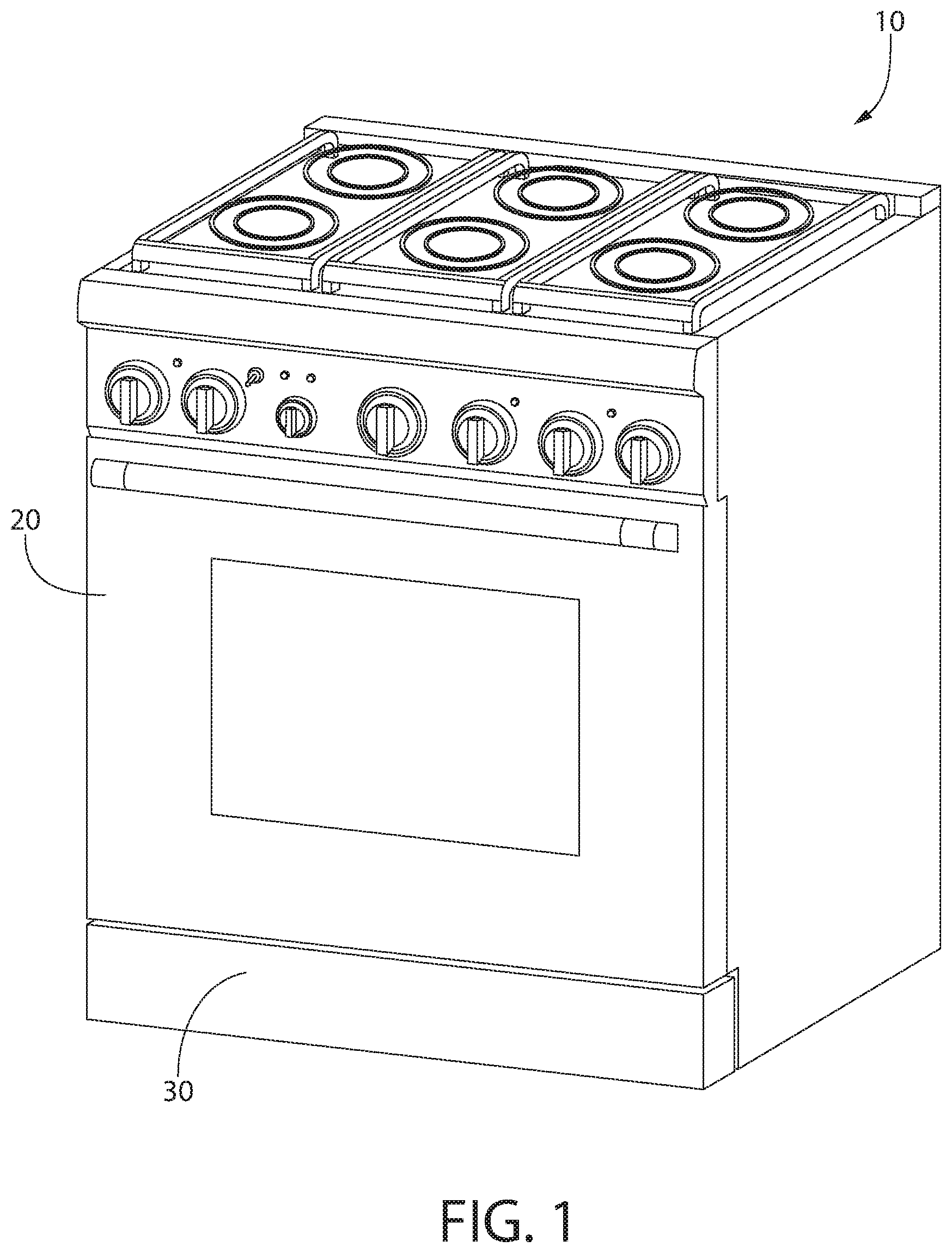
[0014] FIG. 1 is a perspective schematic view of an exemplary appliance in accordance with embodiments of the invention;
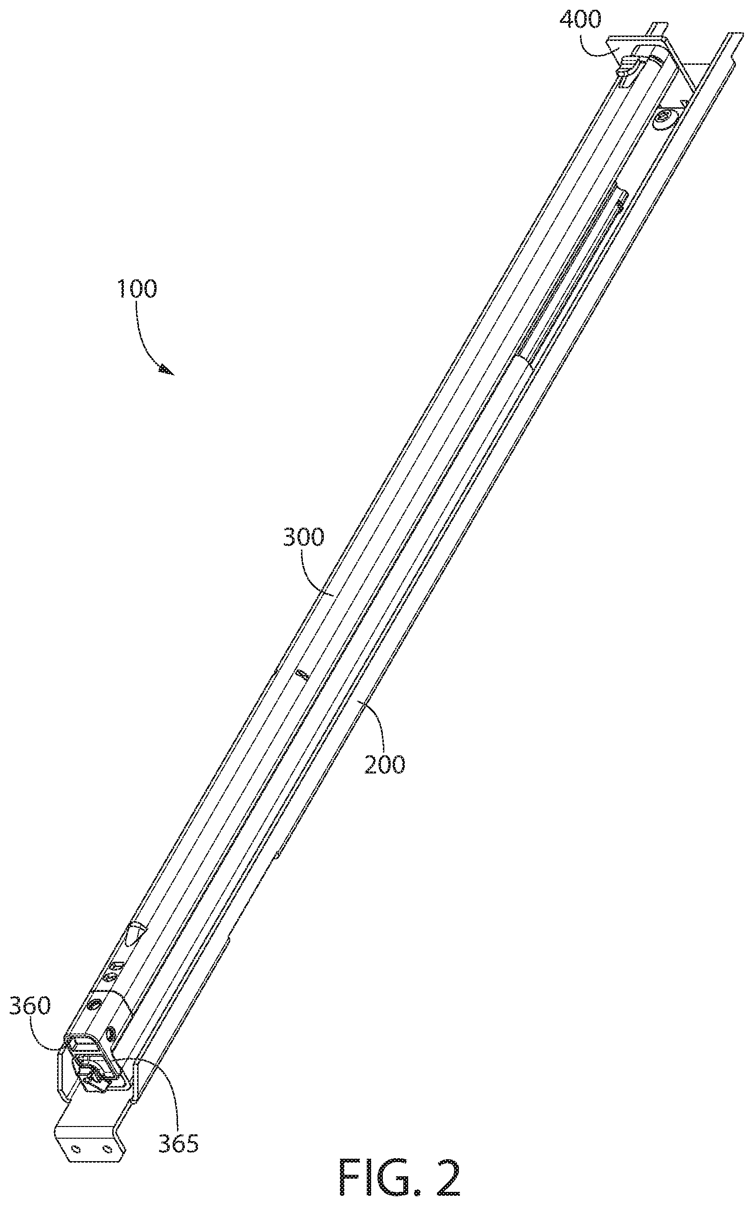
[0015] FIG. 2 is a perspective view of an exemplary slide assembly in accordance with embodiments of the invention;
[0016] FIG. 3 is a perspective view of the exemplary slide assembly shown in FIG. 2;
[0017] FIG. 4 is a perspective view of the exemplary slide assembly shown in FIG. 2 in a partially disassembled state;
[0018] FIG. 5 is a side view of the exemplary slide assembly shown in FIG. 2 with the slide in a retracted state;
[0019] FIG. 6 is a bottom view of the exemplary slide assembly shown in FIG. 2; and
[0020] FIG. 7 is side view of the exemplary slide assembly shown in FIG. 5 with the slide in an extended state.
DETAILED DESCRIPTION
[0021] The invention is described herein with reference to the accompanying drawings in which exemplary embodiments of the invention are shown. The invention may, however, be embodied in many different forms and should not be construed as limited to the embodiments set forth herein.
[0022] As explained above, embodiments of the invention provide an improvement to a domestic oven or other domestic home appliance.
[0023] FIG. 1 shows an example of a domestic home appliance 10, in this example a range, in accordance with embodiments of the invention. Appliance 10 has a door 20 that provides access to a cooking compartment, and a drawer 30 that is, in this example, a warming drawer. In this example, drawer 30 slides relative to appliance 10 between a closed position and an open position by way of two slide assemblies. While two slide assemblies are used in this example, other embodiments use one, three, or more slide assemblies. Embodiments of the invention are directed to the slide assemblies used to attach drawer 30 to appliance 10, and to appliances that use the slide assemblies.
[0024] As stated above, the slide assemblies can become worn and/or their operation can be adversely affected by food or other debris becoming lodged in the assemblies. As a result, non-destructive removal of the slide assemblies, or a portion thereof, for cleaning or replacement is advantageous.
[0025] In some cases, a drawer can become dislodged from an appliance during shipping of the appliance. This can be due to a slide separating from a slide bracket. Such separating during shipping, or during use, can result in a service call from the end user. Embodiments of the invention help limit or prevent such service calls.
[0026] FIGS. 2 and 3 show an example of a slide assembly 100 in accordance with embodiments of the invention. Slide assembly 100 includes, in this example, a slide bracket 200 and a slide 300. Slide bracket 200 is attached to a main body of appliance 10 and is positionally fixed relative to the main body of appliance 10. Slide 300 has two main portions (explained in more detail below): a first portion that is attached to slide bracket 200; and a second portion that moves relative to the first portion. Also shown in FIGS. 2 and 3 is a slide retainer 400 that is removably attached to slide bracket 200.
[0027] FIG. 4 shows a partially disassembled view of slide assembly 100. In FIG. 4, slide 300 is shown removed from slide bracket 200 and slide retainer 400 is shown removed from slide bracket 200. In this example, slide bracket 200 has a body 210 that includes a planar base portion and two upturned side portions that form right angles with the planar base portion. One purpose of the upturned side portions is to add strength and rigidity to slide bracket 200. Slide bracket 200 also has, in this example, a downturned end portion that has two holes (better seen in FIG. 2) used to removably fasten slide bracket 200 to the main body of appliance 10. Other and/or additional features and methods can be used to attached slide bracket 200 to the main body of appliance 10 such as, for example, screws, rivets, adhesive, friction fit attachments, slots and lances, welding, or any other attachment. In this example, slide bracket 200 is positionally fixed relative to the main body of appliance 10 when slide bracket 200 is in the operating position, and is removable.
[0028] FIG. 4 shows slide 300 removed from slide bracket 200. In this example, slide 300 is attached to slide bracket 200 by four sets of engagement devices. Slide bracket 200 has four openings 220 in its planar base portion. Openings 220 are of an appropriate size and shape to receive respective lances 340 on slide 300. In this example, the four openings 220 are larger at one end than the other end (see FIG. 6) to facilitate the insertion of lances 340 into openings 220. To attach slide 300 to slide bracket 200, slide 300 is lowered onto slide bracket 300 such that each lance 340 enters one opening 220, and then slide 300 is moved in direction A shown in FIG. 4. This movement cases lances 340 to engage the planar base portion of slide bracket 200 and pinch the planar base portion of slide bracket 200 between lances 340 and a bottom surface of slide 300. FIG. 6 shows lances 340 engaged with openings 220.
[0029] FIG. 4 shows slide 300 as having a first part 320 and a second part 310. In this example, lances 340 are integrally formed in a lower side of a body portion 330 of first part 320 of slide 300. When lances 340 are engaged with openings 220 (as described above), first part 320 of slide 300 is positionally fixed relative to slide bracket 200 and, therefore, positionally fixed relative to the main body of appliance 10. Second part 310 of slide 300 is attached to first part 320 of slide 300 such that second part 310 slides relative to first part 320. Second part 310 is configured to attach to drawer 30 such that second part 310 is positionally fixed relative to drawer 30 and moves with drawer 30. Due to slide 300 being attached to drawer 30 and the main body of appliance 10 as described above, drawer 30 is attached to the main body of appliance 10 in a manner that drawer 30 can move relative to the main body of appliance 10 between a closed position and at least one open position.
[0030] When drawer 30 is moved to a fully open position (in direction A), force can be transmitted in direction A from second part 310 to first part 320. This force will tend to push lances 340 more tightly into openings 220 and, therefore, keep first part 320 securely attached to slide bracket 200. An opposite force can be applied to the connection between lances 340 and openings 220 when drawer 30 is moved from an open position to the closed position (in direction B).
[0031] When drawer 30 is moved from an open position to the closed position and/or when drawer 30 is jarred (during shipping of appliance 10, for example), force can be transmitted in direction B from second part 310 to first part 320. Without features of the invention, this force could tend to push lances 340 out of engagement with openings 220 and, therefore, result in first part 320 becoming dislodged from slide bracket 200. To prevent this undesirable disassociation of first part 320 and slide bracket 200, slide retainer 400 is provided as a stop to limit the movement of second part 310 of slide 300 in direction B.
[0032] When drawer 30 is moved to the closed position and/or when drawer 30 is jarred, an end 350 of second part 310 contacts a plate-like portion (in this example) of slide retainer 400 and limits the movement of second part 310 in direction B. By limiting the movement of second part 310 in direction B, little or no force in direction B is transmitted to first part 300 and, as a result, little or no force in direction B is transmitted to lances 340. In this manner, slide retainer 400 prevents, or at least greatly reduces the chance of, slide 300 being dislodged from slide bracket 200.
[0033] In order to allow the assembly of lances 340 into openings 220 discussed above, slide retainer 400 is removably attached to slide bracket 200 with, in this example, a screw 440. During attachment of slide retainer 400 to slide bracket 200, a front flange 430 is inserted into a slot in slide bracket 200 and screw 440 is inserted though a hole in slide bracket 200 and threaded into front flange 430. By locating front flange 430 below slide bracket 200, front flange 430 is less likely to be separated from slide bracket 200 by force in direction B. In this example, two rear flanges 420 extend from plate-like portion 410 and rest on slide bracket 200 to provide additional resistance to plate-like portion 410 bending under forces in direction B.
[0034] Slide 300 is assembled to slide bracket 200 before slide retainer 400 is attached to slide bracket 200. This allows slide 300 to be positioned above slide bracket 200 and moved in direction A to engage lances 340 in openings 220. After lances 340 are fully engaged in openings 220, slide retainer 400 is attached to slide bracket 200 and movement of second part 310 of slide 300 in direction B is prevented.
[0035] FIG. 5 shows a side view of slide 300 assembled on slide bracket 200 with slide retainer 400 in position. In this view, slide 300 is in the fully retracted position (drawer 30 in the closed position). In this example, a slide stop 365 is provided at a front end 360 of second part 310 of slide 300. A rear face of slide stop 365 is shown contacting an end of first part 320 of slide 300. Slide stop 365 limits the travel of second part 310 relative to first part 320 in direction B. In some embodiments, this movement-limiting feature of slide stop 365 is only beneficial before slide 300 is attached to slide bracket 200 and before slide retainer 400 is in position. At such times, slide stop 365 prevents second part 310 from travelling in direction B to a position that might cause damage to slide 300 or cause second part 310 to become separated from first part 320.
[0036] In some embodiments, slide stop 365 is prevented from contacting first part 320 by end 350 of second part 310 contacting slide retainer 400. In such embodiments, slide retainer 400 prevents any force in direction B from being directly transmitted from slide stop 365 to first part 320. Such a transmission of force could be undesirable because it could cause lances 340 to become dislodged from openings 220.
[0037] In some embodiments, slide stop 365 contacts first part 320 simultaneously with end 350 of second part 310 contacting slide retainer 400. In such embodiments, slide retainer 400 prevents any movement in direction B of first part 320 by slide stop 365.
[0038] FIG. 6 shows a bottom view of slide bracket 200 with slide 300 and slide retainer 400 attached to slide bracket 200. Lances 340 can be seen engaged with openings 220, and front flange 430 can be seen below slide bracket 200.
[0039] FIG. 7 is similar to FIG. 5 except that FIG. 7 shows second part 310 in an extended position (drawer 30 in an open position). This example shows a telescoping configuration of slide 300. It is noted that telescoping configurations having more or few parts, or other sliding configurations can be used. Various type of slide assemblies can be a part of embodiments of the invention including, but not limited to, soft-close slides and other slides.
[0040] The Figs. show various protrusions, clips, and fastener holes for attaching drawer 30 to second part 310 of slide 300. It is noted that more or fewer of these, and/or other, attachment features can be used.
[0041] It will be appreciated that variants of the above-disclosed and other features and functions, or alternatives thereof, may be combined into many other different systems or applications. Any of the features described above can be combined with any other feature described above as long as the combined features are not mutually exclusive. Various presently unforeseen or unanticipated alternatives, modifications, variations or improvements therein may be subsequently made by those skilled in the art which are also intended to be encompassed by the invention.
* * * * *
D00000
D00001
D00002
D00003
D00004
D00005
D00006
D00007
XML
uspto.report is an independent third-party trademark research tool that is not affiliated, endorsed, or sponsored by the United States Patent and Trademark Office (USPTO) or any other governmental organization. The information provided by uspto.report is based on publicly available data at the time of writing and is intended for informational purposes only.
While we strive to provide accurate and up-to-date information, we do not guarantee the accuracy, completeness, reliability, or suitability of the information displayed on this site. The use of this site is at your own risk. Any reliance you place on such information is therefore strictly at your own risk.
All official trademark data, including owner information, should be verified by visiting the official USPTO website at www.uspto.gov. This site is not intended to replace professional legal advice and should not be used as a substitute for consulting with a legal professional who is knowledgeable about trademark law.