Planning Apparatus For Determining An Ablation Probe Parameter For A Single Ablation Probe Or For Multiple Ablation Probes
TOKOUTSI; ZOI ; et al.
U.S. patent application number 16/965233 was filed with the patent office on 2020-11-26 for planning apparatus for determining an ablation probe parameter for a single ablation probe or for multiple ablation probes. The applicant listed for this patent is KONINKLIJKE PHILIPS N.V.. Invention is credited to MARCO BARAGONA, MARTIN GREPL, ALFONSO AGATINO ISOLA, JACEK LUKASZ KUSTRA, RALPH THEODORUS HUBERTUS MAESSEN, ZOI TOKOUTSI, KAREN VEROY-GREPL.
| Application Number | 20200367591 16/965233 |
| Document ID | / |
| Family ID | 1000005074162 |
| Filed Date | 2020-11-26 |


View All Diagrams
| United States Patent Application | 20200367591 |
| Kind Code | A1 |
| TOKOUTSI; ZOI ; et al. | November 26, 2020 |
PLANNING APPARATUS FOR DETERMINING AN ABLATION PROBE PARAMETER FOR A SINGLE ABLATION PROBE OR FOR MULTIPLE ABLATION PROBES
Abstract
A patch pocket folding apparatus (1) comprises: a template (2), moving means (3) of the template (2), a folding body (4), against which the template (2) pushes a fabric (T), folding blades (5), a folding unit (G) disposed under the folding body (4); the folding unit (G) is composed of a set of strips (6) made of an easily workable rigid material that are fixed under the folding body (4) and define an internal corresponding border having the same profile as the external border of the template (2).
| Inventors: | TOKOUTSI; ZOI; (EINDHOVEN, NL) ; GREPL; MARTIN; (EINDHOVEN, NL) ; BARAGONA; MARCO; (DELFT, NL) ; ISOLA; ALFONSO AGATINO; (EINDHOVEN, NL) ; KUSTRA; JACEK LUKASZ; (EINDHOVEN, NL) ; MAESSEN; RALPH THEODORUS HUBERTUS; (ROERMOND, NL) ; VEROY-GREPL; KAREN; (EINDHOVEN, NL) | ||||||||||
| Applicant: |
|
||||||||||
|---|---|---|---|---|---|---|---|---|---|---|---|
| Family ID: | 1000005074162 | ||||||||||
| Appl. No.: | 16/965233 | ||||||||||
| Filed: | January 17, 2019 | ||||||||||
| PCT Filed: | January 17, 2019 | ||||||||||
| PCT NO: | PCT/EP2018/051102 | ||||||||||
| 371 Date: | July 27, 2020 |
| Current U.S. Class: | 1/1 |
| Current CPC Class: | A41H 33/00 20130101; A41D 27/20 20130101; D06F 89/026 20130101 |
| International Class: | A41H 33/00 20060101 A41H033/00; A41D 27/20 20060101 A41D027/20; D06F 89/02 20060101 D06F089/02 |
Foreign Application Data
| Date | Code | Application Number |
|---|---|---|
| Jan 20, 2017 | IT | 102017000006412 |
| Jun 30, 2017 | IT | 102017000073778 |
Claims
1. A planning apparatus for determining an ablation probe parameter describing an operation of an ablation probe during an ablation procedure for ablating a part of a subject, the planning apparatus comprising: a thermal energy determination providing unit configured to provide a first thermal energy function defining a relation between a first thermal energy distribution to be calculated and a spatial temperature distribution and to provide a temperature-based condition being indicative of a desired treatment outcome for the subject including an ablation of the part of the subject, a thermal energy determination unit configured to determine the first thermal energy distribution by using the first thermal energy function such that the temperature-based condition is fulfilled, an ablation probe parameter determination providing unit configured to provide a second thermal energy function providing a relation between a) a second thermal energy distribution to be calculated and to be caused by the ablation probe and b) the ablation probe parameter, an ablation probe parameter determination unit configured to determine the ablation probe parameter by using the second thermal energy function such that a deviation between the first thermal energy distribution and the second thermal energy distribution fulfils a predefined deviation criterion.
2. The planning apparatus as defined in claim 1, wherein the thermal energy determination providing unit is further configured to provide a) a spatial distribution of different components of the subject in a region including the part to be ablated and b) thermal properties of the different components, and to provide the thermal energy function such that it depends on the spatial distribution of the different components and the thermal properties of the different components, wherein the thermal energy determination unit is configured to determine the first thermal energy distribution by using the thermal energy function based on the spatial distribution of the different components and the thermal properties of the different components such that the temperature-based condition is fulfilled.
3. The planning apparatus as defined in claim 1, wherein the thermal energy determination providing unit and the thermal energy determination unit are configured such that the temperature-based condition is based on a deviation between a provided desired spatial temperature distribution being indicative of the desired treatment outcome, wherein the desired spatial temperature distribution includes temperature values within the part to be ablated, wherein the temperature values are larger than a threshold temperature above such part that is ablated, and a calculated spatial temperature distribution resulting from using the first thermal energy function while determining the first thermal energy distribution.
4. The planning apparatus as defined in claim 1, wherein the thermal energy determination unit is configured to provide a user interface allowing a user to intervene in the determination of the first thermal energy distribution.
5. The planning apparatus as defined in claim 4, wherein the thermal energy determination unit is configured to provide the user interface such that the user is allowed to define a set of thermal energy distributions, wherein the thermal energy determination unit is configured to determine the first thermal energy distribution such that it is within the defined set of thermal energy distributions.
6. The planning apparatus as defined in claim 3, wherein the thermal energy determination unit is configured such that the deviation of the calculated spatial temperature distribution and the desired spatial temperature distribution is a weighted deviation, wherein deviations in different regions of the subject are considered with different weights, wherein the different regions include at least a first region being defined by the part of the subject to be ablated and a second region that does not include the part of the subject to be ablated, wherein the thermal energy determination unit is configured to provide the user interface such that the user is allowed to define the different weights.
7. The planning apparatus as defined in claim 4, wherein the thermal energy determination unit is configured to provide an output being indicative of a calculated spatial temperature distribution resulting from using the first thermal energy function while determining the first thermal energy distribution, in order to allow the user to review a corresponding treatment outcome, and to provide the user interface such that it allows the user to modify at least one of the first thermal energy function and the temperature-based condition and to initiate a further determination of the first thermal energy distribution based on the modification.
8. The planning apparatus as defined in claim 1, wherein the planning apparatus further comprises an evaluation unit configured to evaluate a calculated spatial temperature distribution resulting from using the first thermal energy function while determining the first thermal energy distribution based on a predefined evaluation criterion, wherein the thermal energy determination unit is adapted to modify at least one of the first thermal energy function and the temperature-based condition and to repeat the determination of the first thermal energy distribution based on the modification, if the evaluation indicates that the calculated spatial temperature distribution and hence the corresponding treatment outcome is insufficient.
9. The planning apparatus as defined in claim 1, wherein the ablation probe parameter determination providing unit and the ablation probe parameter determination unit are configured such that the ablation probe parameter includes at least one of a placement of the ablation probe relative to the part to be ablated and a power to be applied by the ablation probe.
10. The planning apparatus as defined in claim 1, wherein the ablation probe parameter determination providing unit and the thermal energy determination providing unit are configured to determine several ablation probe parameters for several ablation probes iteratively, wherein in each iteration step a further ablation probe is considered and one or several ablation probe parameters of at least the further ablation probe are determined by using the second thermal energy function such that a deviation between the first thermal energy distribution and the second thermal energy distribution fulfils the predefined second deviation criterion, wherein the iteration is stopped, if a predefined termination criterion is fulfilled.
11. The planning apparatus as defined in claim 10, wherein the ablation probe parameter determination providing unit and the thermal energy determination providing unit are configured to consider in each iteration step a thermal energy distribution defined by a difference between the first thermal energy distribution and a thermal energy distribution that has been determined in the previous iteration by using the second thermal energy function.
12. The planning apparatus as defined in claim 11, wherein the ablation probe parameter determination providing unit and the thermal energy determination providing unit are configured to determine in an iteration step only the one or several ablation probe parameters of the further ablation probe considered in the respective iteration step.
13. An ablation system for ablating a part of a subject, the ablation system comprising: a planning apparatus configured to determine an ablation probe parameter describing an operation of an ablation probe during an ablation procedure for ablating the part of the subject as defined in claim 1, and an ablation probe configured to be operated in accordance with the determined ablation probe parameter.
14. A planning method for determining an ablation probe parameter describing an operation of an ablation probe during an ablation procedure for ablating a part of a subject, the planning method comprising: providing a first thermal energy function defining a relation between a first thermal energy distribution to be calculated and a spatial temperature distribution and to provide a temperature-based condition being indicative of a desired treatment outcome for the subject including an ablation of the part of the subject, determining the first thermal energy distribution by using the thermal energy function such that the temperature-based condition is fulfilled, providing a second thermal energy function providing a relation between a) a second thermal energy distribution to be calculated and to be caused by the ablation probe and b) the ablation probe parameter, determining the ablation probe parameter by using the second thermal energy function such that a deviation between the first thermal energy distribution and the second thermal energy distribution fulfils a predefined deviation criterion.
15. A planning computer program for determining an ablation probe parameter describing an operation of an ablation probe during an ablation procedure for ablating a part of a subject, wherein the planning computer program comprises program code means for causing a planning apparatus as defined in claim 1 to carry out the planning method as defined in claim 14, when the computer program is run on the planning apparatus.
Description
[0001] The present patent application for industrial invention relates to an improved patch pocket folding apparatus.
[0002] The application of patch pockets or pockets of another type on pants, aprons, shirts or similar garments is currently obtained by using a machine that comprises a folding apparatus that folds and applies the pocket on a piece of fabric.
[0003] For a better understanding of the invention, the prior art is described with reference to FIGS. 1, 2 and 3, wherein:
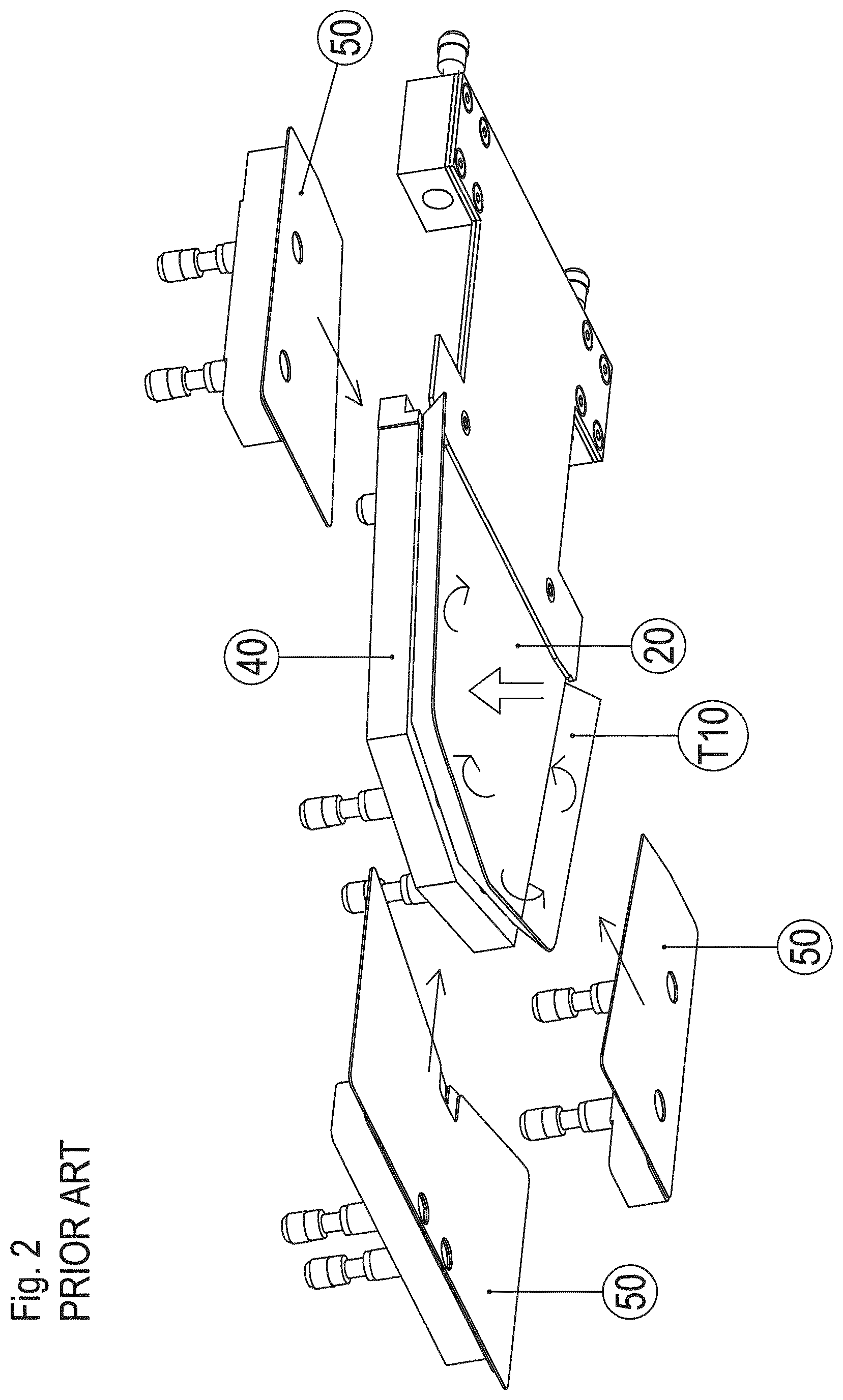
[0004] FIG. 1 is an exploded axonometric view of a traditional folding apparatus;
[0005] FIG. 2 is a partially exploded view of the folding apparatus of FIG. 1, wherein the template is in operating position and the fabric used for the pocket penetrates inside the shaped cavity of the folding body;
[0006] FIG. 3 is the same as FIG. 2, except for the fact that the folding blades are in contracted position, close to each other, and the template is partially disposed between said folding blades and the folding body;
[0007] FIGS. 3A, 3B and 3C are three diagrammatic front views that show the steps of the pocket folding process with the folding apparatus according to the prior art.
[0008] The attached figures diagrammatically show a folding apparatus that is traditionally used to fold and form patch pockets.
[0009] With reference to FIG. 1, the folding apparatus (10) comprises a template (20) provided with an external border that has the same profile as the pocket to be formed, and a rigid folding body (40) that is suitable for cooperating with the template (20) and provided with a shaped cavity (41) having the same profile as the pocket to be formed.
[0010] The template (20) comprises a first surface, which is directed towards the folding body (40), and a second surface, which is directed towards the opposite side.
[0011] It must be noted that the folding and forming process of a patch pocket provides for preparing a fabric (T) used to make the pocket to be formed, having larger dimensions than the template (20) and consequently comprising exceeding edges (T10) that protrude towards the exterior of the template (20), as shown in FIG. 2.
[0012] With reference to FIGS. 1 and 2, the template (20) may be disposed in two positions, of which: [0013] an idle position, wherein the template (20) is raised relative to the folding body (40), as shown in FIG. 1; [0014] a operating position, wherein the template (20) penetrates inside the shaped cavity of the folding body (40), as shown in FIG. 2.
[0015] More precisely, when the template (20) is in idle position, the fabric (T) can be disposed between the template (20) and the folding body (40) in such way that, when the template (20) is in operating position, said fabric (T) penetrates inside the shaped cavity (41) of the folding body (40).
[0016] The folding apparatus (10) also comprises moving means (30) of said template (20) that move the templates (20) between the two positions.
[0017] Advantageously, said moving means (30) of the template (20) comprise an actuator that pushes the template (20) towards said folding body (40) in such a way to press the fabric (T) against it.
[0018] With reference to FIGS. 1 and 3, the folding apparatus (10) comprises three folding blades (50), of which a front folding blade and two lateral folding blades.
[0019] Specifically, said three folding blades (50) are moved between two positions, of which: [0020] a divergent position, wherein the folding blades (5) are spaced in order to let the template (2) pass from its idle position to its operating position; [0021] a contracted position, which is only possible when the template (20) is in operating position; in said contracted position, the folding blades (5) are close to each other so that the template (2) is partially disposed between said folding blades (5) and said folding body (4).
[0022] The description of the prior art continues with reference to the operating mode of the folding apparatus (10) during the folding and the forming process of a patch pocket.
[0023] With reference to FIGS. 1 and 2, when the fabric (T) is disposed on the folding body (40) between the folding body (40) and the template (20), and the actuator (30) pushes the template (20) downwards, in operating position, the template (20) and the fabric (T) are inserted inside the shaped cavity (41) of the folding body (40).
[0024] Because of the penetration of the template (20) inside the shaped cavity (41), the exceeding edges (T10) of the fabric (T) that protrude towards the exterior of the template (20) are raised, as shown in FIG. 2.
[0025] Once the exceeding edges (T10) of the fabric (T) are raised, the folding blades (50) pass from the divergent position to the contracted position, in such a way that the raised edges (T10) of the fabric (T) are folded and adhere to the second surface of the template (20), as shown in FIG. 3.
[0026] Every time the shape and/or the dimensions of the patch pocket are to be changed, such a folding apparatus requires to replace also the folding body (40), in addition to the template (20), because said parts are specifically made according to the shape and the dimensions of the pocket to be formed.
[0027] Alternatively, a folding body with an elastic, deformable portion can be used. In order to form the fabric, the template pushes the pocket against said elastic portion, deforming such elastic portion and folding the edges of the pocket.
[0028] The provision of such a folding body makes it possible to adjust said folding body to any template, regardless of its shape and dimensions. Consequently, even when the shape and the dimensions of the pocket are to be changed, the replacement of the folding body with the elastic portion is not necessary. Moreover, not being subject to plastic deformation, at the end of its use, the elastic portion returns to the initial shape and dimensions and can be used cyclically, regardless of the shape of the pocket to be made.
[0029] Such a folding body with the elastic portion is impaired by the poor quality of the pockets because the edges of the pockets folded with such a folding body do not have a well-defined profile. As a matter of fact, when the template presses the pocket against the elastic portion, said elastic portion is deformed and creates rounded edges. In this way, also the folding edges of the pocket are rounded, and not well-defined.
[0030] Moreover, because of the lack of sharp corners, the edges (T10) of the pocket (T) tend to open as soon as the folding blades (50) pass from the contracted position to the divergent position, at the end of the folding process of the edges (T10) of the pocket (T) under the template (20).
[0031] Otherwise said, because of the lack of sharp corners, the folding lines of the pockets folded by means of the folding apparatus with the elastic portion are not well-defined, and the edges tend to open again, thus frustrating the folding operation.
[0032] U.S. Pat. No. 4,445,631 describes a patch pocket folding apparatus comprising a folding body and a holding blade suitable for supporting a fabric with larger dimensions than the template. The folding apparatus comprises moving means of the holding blade, which are connected to the holding blade to move the holding blade between an idle position, wherein the holding blade is in distal position relative to the folding body, and an operating position, wherein the holding blade pushes the fabric against the folding body. When the holding blade is in operating position, the fabric is disposed between the holding blade and the folding assembly.
[0033] The folding body comprises a smooth plate and a folding assembly is disposed under the smooth plate of the folding body.
[0034] Said folding assembly comprises a shaped plate fixed under the smooth plate of the folding body. Such a plate is specifically made according to the shape and the dimensions of the pocket to be formed, in such a way to define an internal corresponding edge of the folding assembly.
[0035] Evidently, the use of a similar folding assembly implies that, every time it is necessary to change the shape and/or the dimensions of the patch pocket, in addition to the template, it is also necessary to replace the shaped plate of the folding unit, with an inevitable waste of time and money.
[0036] DE4113131 describes a patch pocket folding apparatus comprising a folding body and a holding blade suitable for supporting a piece of fabric. The folding body comprises a smooth plate and a folding assembly is disposed under the folding body. Said folding assembly is made of Velcro and is therefore elastic and deformable. In view of the above, the holding blade pushes the fabric against the folding body, deforming the folding assembly and folding the edges of the fabric. Said folding assembly is impaired by the fact that the quality of the pockets is not satisfactory because the edges of the pockets folded with such a folding assembly do not have a well-defined profile. As a matter of fact, when the holding blade presses the fabric against the folding assembly, said folding assembly is deformed and creates rounded edges. In this way, also the folding edges of the pocket are rounded, and not well-defined. Moreover, because of the lack of sharp corners, the edges of the pockets folded with said folding assembly of elastic, deformable material tend to open again, thus frustrating the folding operation.
[0037] The purpose of the present invention is to devise a folding apparatus for folding and forming patch pockets that is inexpensive and easy to make, and does not require to use complicated machines for making the folding body.
[0038] Another purpose is to devise a folding apparatus for folding and forming patch pockets that is capable of making high-quality pockets.
[0039] The folding apparatus for forming and ironing patch pockets comprises a template provided with an external border that has the same profile as the pocket to be formed. The template can be in an idle position and in an operating position.
[0040] The folding apparatus comprises moving means to move the template between the idle position and the operating position.
[0041] The folding apparatus comprises a folding body against which the template in operating condition pushes a fabric suitable for being disposed between the template and the folding body.
[0042] The folding apparatus comprises folding blades that move between two positions, namely a divergent position, wherein the folding blades are spaced in order to let the template pass from its idle position to its operating position, and a contracted position, wherein the folding blades are close to each other and the template is partially disposed between the folding blades and the folding body.
[0043] The folding apparatus of the invention also comprises a folding unit disposed under the folding body. The folding unit is configured in such a way to define an internal corresponding border having the same profile as the external border of the template.
[0044] The peculiarity of the folding apparatus according to the invention consists in the fact that the folding unit is composed of a set of strips made of an easily workable rigid material. The strips are fixed under the folding body and define the internal corresponding edge.
[0045] The advantages of the folding apparatus according to the invention are evident, wherein the provision of a folding unit composed of a set of strips permits to change the shape and the dimensions of the internal corresponding edge of the folding unit in a simple, practical and inexpensive way. In fact, the strips can be changed easily and rapidly changed in such a way to obtain an internal corresponding edge of the folding unit with different shape and dimensions without having to replace the folding body.
[0046] For the sake of clarity, the description of the folding apparatus according to the invention continues with reference to the attached drawings, which have a merely illustrative, not limiting value, wherein:
[0047] FIG. 1 is an exploded axonometric view of a traditional folding apparatus;
[0048] FIG. 2 is a partially exploded view of the folding apparatus of FIG. 1, wherein the template is in operating position and the fabric used for the pocket penetrates inside the shaped cavity of the folding body;
[0049] FIG. 3 is the same as FIG. 2, except for the fact that the folding blades are in contracted position, close to each other, and the template is disposed between said folding blades and the folding body;
[0050] FIGS. 3A, 3B and 3C are three diagrammatic front views that show the steps of the pocket folding process with the folding apparatus according to the prior art;
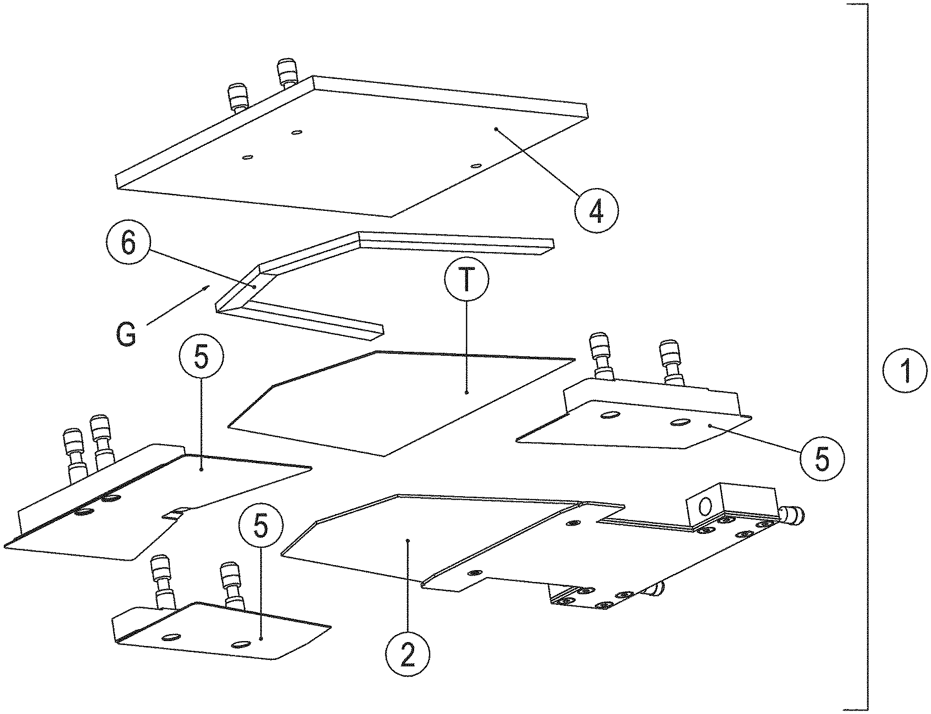
[0051] FIG. 4 is an exploded axonometric view of the folding apparatus according to the invention;
[0052] FIG. 4A is a partially exploded view of the folding apparatus of FIG. 4, wherein the template is in operating position and the fabric penetrates inside the shaped cavity of the folding body;
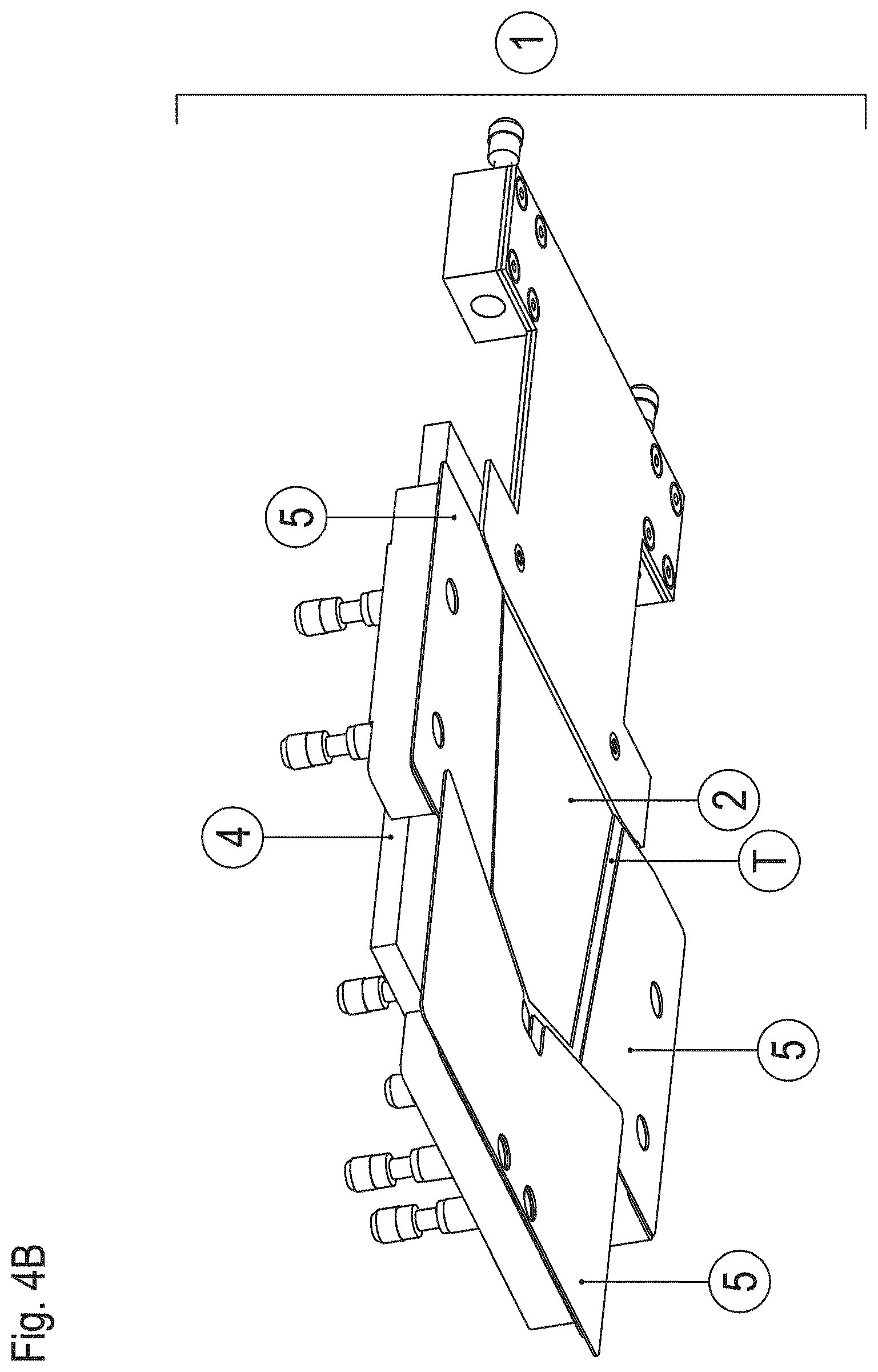
[0053] FIG. 4B is the same as FIG. 4A, except for the fact that the folding blades are in contracted position and the template is disposed between the folding blades and the folding body;
[0054] FIGS. 4C, 4D and 4E are three diagrammatic front views that show the steps of the pocket folding process with the folding apparatus of FIG. 4;
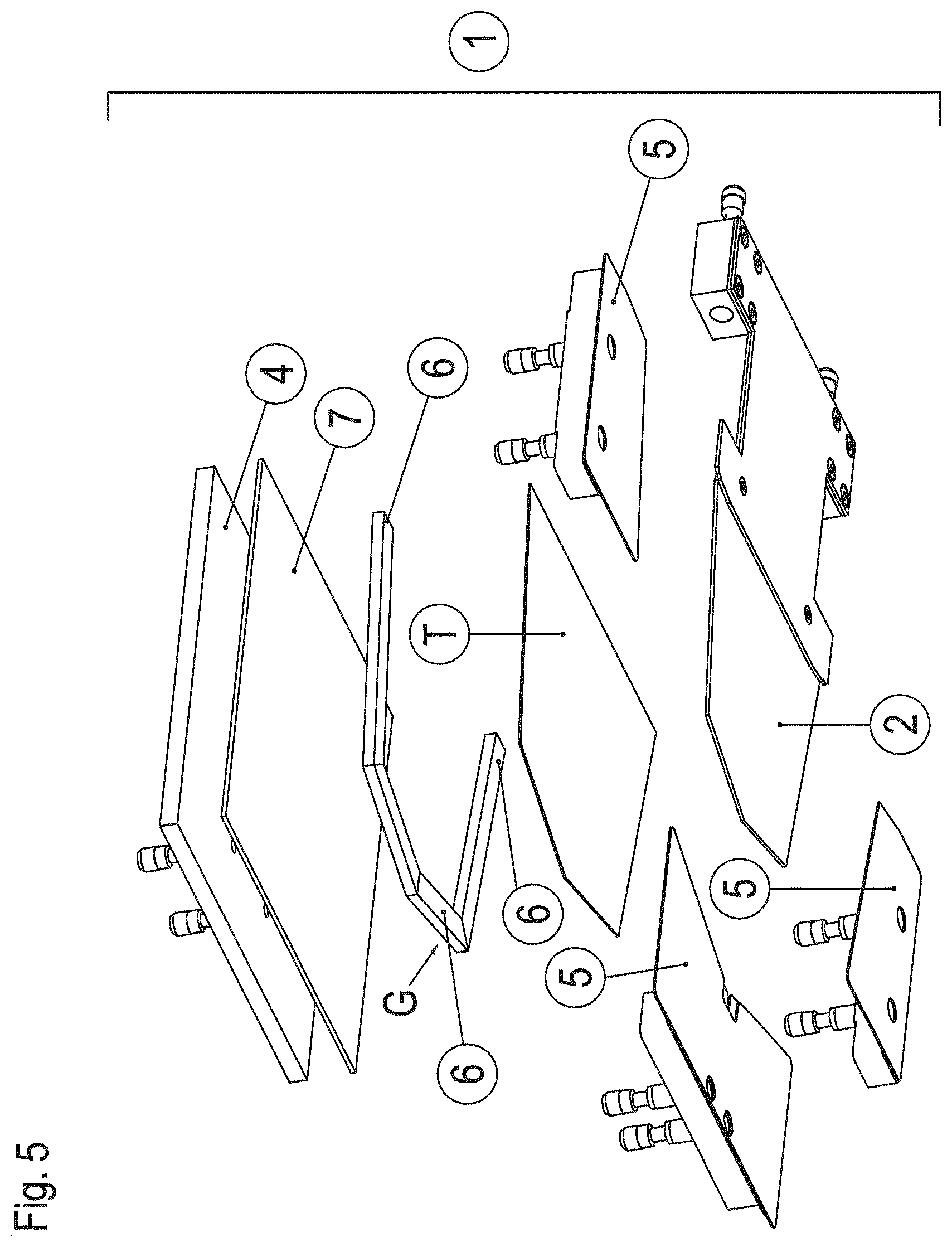
[0055] FIG. 5 is an exploded axonometric view of a first embodiment of the folding apparatus of FIG. 4;
[0056] FIG. 5A is a partially exploded view of the folding apparatus of FIG. 5, wherein the template is in operating position and the fabric penetrates inside the shaped cavity of the folding body;
[0057] FIG. 5B is the same as FIG. 5A, except for the fact that the folding blades are in contracted position and the template is disposed between the folding blades and the folding body;
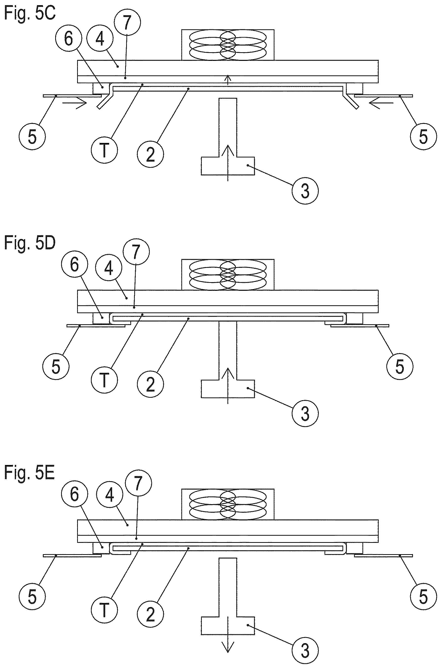
[0058] FIGS. 5C, 5D and 5E are three diagrammatic front views that show the steps of the pocket folding process with the folding apparatus of FIG. 5;
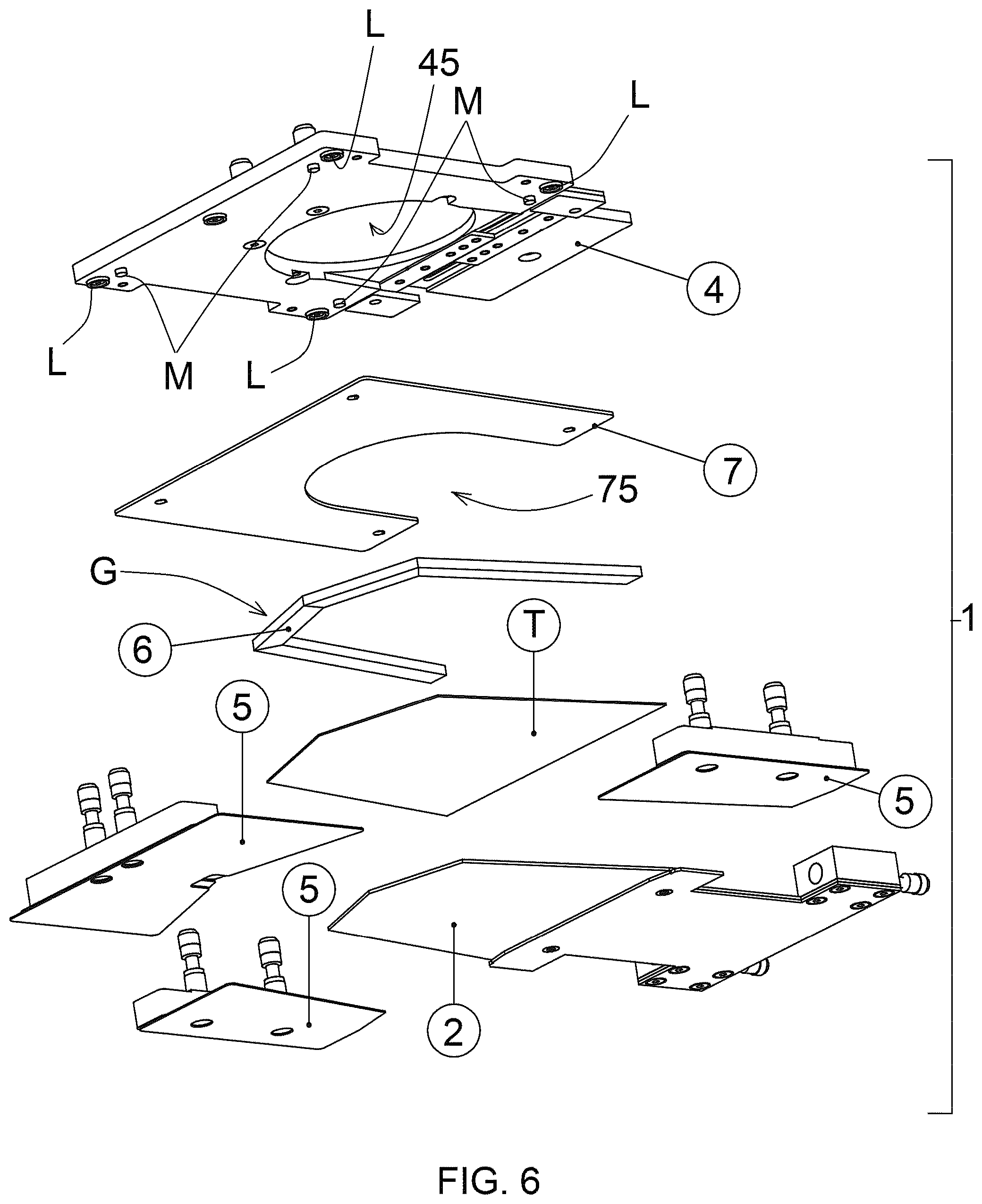
[0059] FIG. 6 is an exploded axonometric view of a second embodiment of the folding apparatus of FIG. 4.
[0060] With reference to the attached figures, the folding apparatus according to the present invention is disclosed, which is generally indicated with reference numeral 1.
[0061] The patch pocket folding apparatus (1) comprises a folding body (4) that consists in a smooth plate, and a template (2) suitable for supporting a fabric (T) with larger dimensions than the template (2). The template (2) has an external border having the same profile as the pocket to be formed with the fabric (T).
[0062] The folding apparatus (1) comprises moving means (3) of the template (2) that are connected to the template (2) in order to move the template (2) between an idle position, shown in FIG. 4, wherein the template (2) is in distal position relative to the folding body (4), and an operating position, shown FIGS. 4A and 4B, wherein the template (2) pushes the fabric (T) against the folding body (4). When the template (2) is in operating position, the fabric (T) is disposed between the template (2) and the folding body (4). Optionally, the moving means (3) are configured in such a way to move the template (2) upwards in order to move the template (2) to its operating position, and downwards in order to move the template (2) to its idle position.
[0063] The folding apparatus (1) comprises folding blades (5) that are moved between a divergent position, shown in FIG. 4A, wherein the folding blades (5) are spaced in order to let the template (2) stop against the folding body (4), and a contracted position, shown in FIG. 4B, wherein the folding blades (5) are close to each other and the template (2) is partially disposed between the folding blades (5) and the folding body (4). When the folding blades (5) are in contracted position, edges (T10) of the fabric (T) that protrude from the template (2) are folded under the template (2).
[0064] The folding apparatus (1) comprises a folding unit (G) disposed under the folding body (4). The folding unit (G) is configured in such a way to define an internal corresponding border having the same profile as the external border of the template (2).
[0065] Said folding unit (G) comprises a set of strips (6) made of an easily workable rigid material, such as for example Plexiglas, plastics, rubber, rigid sponge or wood. Said strips (6) are fixed under the folding body (4) and define the internal corresponding edge.
[0066] The positioning of the template (20) against the folding body (4) makes the edges (T10) of the fabric (T), which protrude towards the exterior of the template (20), raise from the internal corresponding edge of the strips, as shown in FIGS. 4A and 4C.
[0067] Once said edges (T10) of the fabric (T) are raised, the folding blades (50) pass from the divergent position to the contracted position, in such a way that the raised edges (T10) of the fabric (T) are folded and adhere to the second surface of the template (20), as shown in FIGS. 4B, 4D and 4E.
[0068] Evidently, said strips (6) act as sharp corners for folding the fabric (T), thus obtaining a high-quality product. Moreover, said strips (6) can be changed easily and rapidly in such a way to obtain an internal corresponding edge of the folding unit having different shape and dimensions, without having to replace the folding body (4). These operations are simple, practical and inexpensive.
[0069] With reference to FIGS. 5 to 5E, a first embodiment of the folding unit according to the invention is described, wherein the folding unit (G) also comprises a sheet (7) disposed under the folding body (4) that supports the strips (6). In particular, the strips (6) are fixed under the sheet (7). The sheet (7) is made of an easily workable rigid material, such as for example Plexiglas, plastics, rubber, rigid sponge or wood. Because of the provision of both the sheet (7) and the strips (6), the folding unit (G) can be replaced easily.
[0070] FIG. 6 describes a second embodiment of the folding unit according to the invention, wherein the folding body (4) comprises magnets (L) in lower position and the sheet (7) is at least partially made of metal. In particular, the sheet (7) comprises, for instance, small metal plates glued to the sheet (7), in such a way to be attracted by the magnets (L) and firmly connected to the folding body (4).
[0071] The folding body (4) and the folding unit (G) advantageously comprise mutual centering means (M). Said mutual centering means (M) comprise pegs that protrude in lower position from the folding body (4) and holes obtained on the sheet (7) to house the pegs that protrude from the folding body (4).
[0072] Moreover, it must be noted that the sheet (7) of the folding unit (G) according to the invention can comprise a splay (75) and the folding body (4) of the folding unit (G) according to the invention may comprise a hole (45) with vertical axis, which is aligned with the splay (75) of the sheet (7).
[0073] The splay (75) and the hole (45) are suitable for being crossed by a magnet (not shown in the figures) to generate an attraction force that attracts the template (2) and pushes the template (2) against the folding body (4).
[0074] It must be noted that, instead of using the magnets (L), the folding unit (G) can be glued under the folding body (4), or the folding unit (G) can be removably fixed with fast coupling/uncoupling means under the folding body (4).
[0075] Moreover, both the strips (6) and the sheet (L) of the folding unit (G) can be made of metal, in order to be attracted by the magnets of the folding body (4), which may comprise the hole for the magnet that attracts the template.
* * * * *
D00000
D00001
D00002
D00003
D00004
D00005
D00006
D00007
D00008
D00009
D00010
D00011
D00012
D00013
XML
uspto.report is an independent third-party trademark research tool that is not affiliated, endorsed, or sponsored by the United States Patent and Trademark Office (USPTO) or any other governmental organization. The information provided by uspto.report is based on publicly available data at the time of writing and is intended for informational purposes only.
While we strive to provide accurate and up-to-date information, we do not guarantee the accuracy, completeness, reliability, or suitability of the information displayed on this site. The use of this site is at your own risk. Any reliance you place on such information is therefore strictly at your own risk.
All official trademark data, including owner information, should be verified by visiting the official USPTO website at www.uspto.gov. This site is not intended to replace professional legal advice and should not be used as a substitute for consulting with a legal professional who is knowledgeable about trademark law.