Air Pressure Switch, Power Supply Device, And E-cigarettes Containing The Same
OUYANG; Junwei
U.S. patent application number 15/931853 was filed with the patent office on 2020-11-19 for air pressure switch, power supply device, and e-cigarettes containing the same. The applicant listed for this patent is HONG KONG IVPS INTERNATIONAL LIMITED. Invention is credited to Junwei OUYANG.
| Application Number | 20200359697 15/931853 |
| Document ID | / |
| Family ID | 1000004858998 |
| Filed Date | 2020-11-19 |


| United States Patent Application | 20200359697 |
| Kind Code | A1 |
| OUYANG; Junwei | November 19, 2020 |
AIR PRESSURE SWITCH, POWER SUPPLY DEVICE, AND E-CIGARETTES CONTAINING THE SAME
Abstract
The present utility model discloses an air pressure switch, a power supply device using this air pressure switch, and an electronic cigarette using this power supply device. The air pressure switch includes a main body that includes a sensing area that will be triggered under negative pressure. The air pressure switch further includes a flexible protection film installed on the main body and at least the outer surface of the main body where sensing area is provided so that a first cavity is enclosed by the protective film and the surface of the main body where the sensing area is provided and formed. The protective film deforms away from the main body under the external suction force, so that the airflow in the first cavity can partially flow into the space generated by the deformation of the protective film.
| Inventors: | OUYANG; Junwei; (Shenzhen, CN) | ||||||||||
| Applicant: |
|
||||||||||
|---|---|---|---|---|---|---|---|---|---|---|---|
| Family ID: | 1000004858998 | ||||||||||
| Appl. No.: | 15/931853 | ||||||||||
| Filed: | May 14, 2020 |
| Current U.S. Class: | 1/1 |
| Current CPC Class: | A24F 40/53 20200101 |
| International Class: | A24F 40/53 20060101 A24F040/53 |
Foreign Application Data
| Date | Code | Application Number |
|---|---|---|
| May 16, 2019 | CN | 201920715465.3 |
Claims
1. An air pressure switch of an electronic cigarette, wherein the air pressure switch comprises: a main body that comprises an outer surface and a sensing area, wherein the sensing area is triggered by negative pressure; and a flexible protection film installed on the main body and at least a portion of the outer surface of the main body where the sensing area is provided, wherein a first cavity is formed and enclosed by the protective film and the outer surface of the main body where the sensing area is provided; wherein the protective film deforms away from the main body under an external suction force, so that the airflow in the first cavity can partially flow into the space generated by the deformation of the protective film.
2. The air pressure switch of claim 1, wherein the first cavity is an airtight cavity.
3. The air pressure switch of claim 1, wherein either the protective film or the main body includes a supporting element, wherein the protective film is installed on the main body, and two sides of the supporting element are respectively abutted against the outer surface of the main body and a surface of the protective film facing towards the main body, so that the protective film and the main body are arranged at an interval.
4. The air pressure switch of claim 3, wherein the supporting element comprises a ring shape and the area enclosed by inner ring surface of the supporting element is larger than or equal to the area of the sensing area, wherein the sensing area is accommodated in the area enclosed by the inner annular surface of the supporting element when the protective film is installed on the main body, and the protective film that is not covered by the supporting element forms an elastic deformation region.
5. The air pressure switch of claim 4, wherein the area enclosed by inner ring surface of the supporting element is larger than the area of the sensing area.
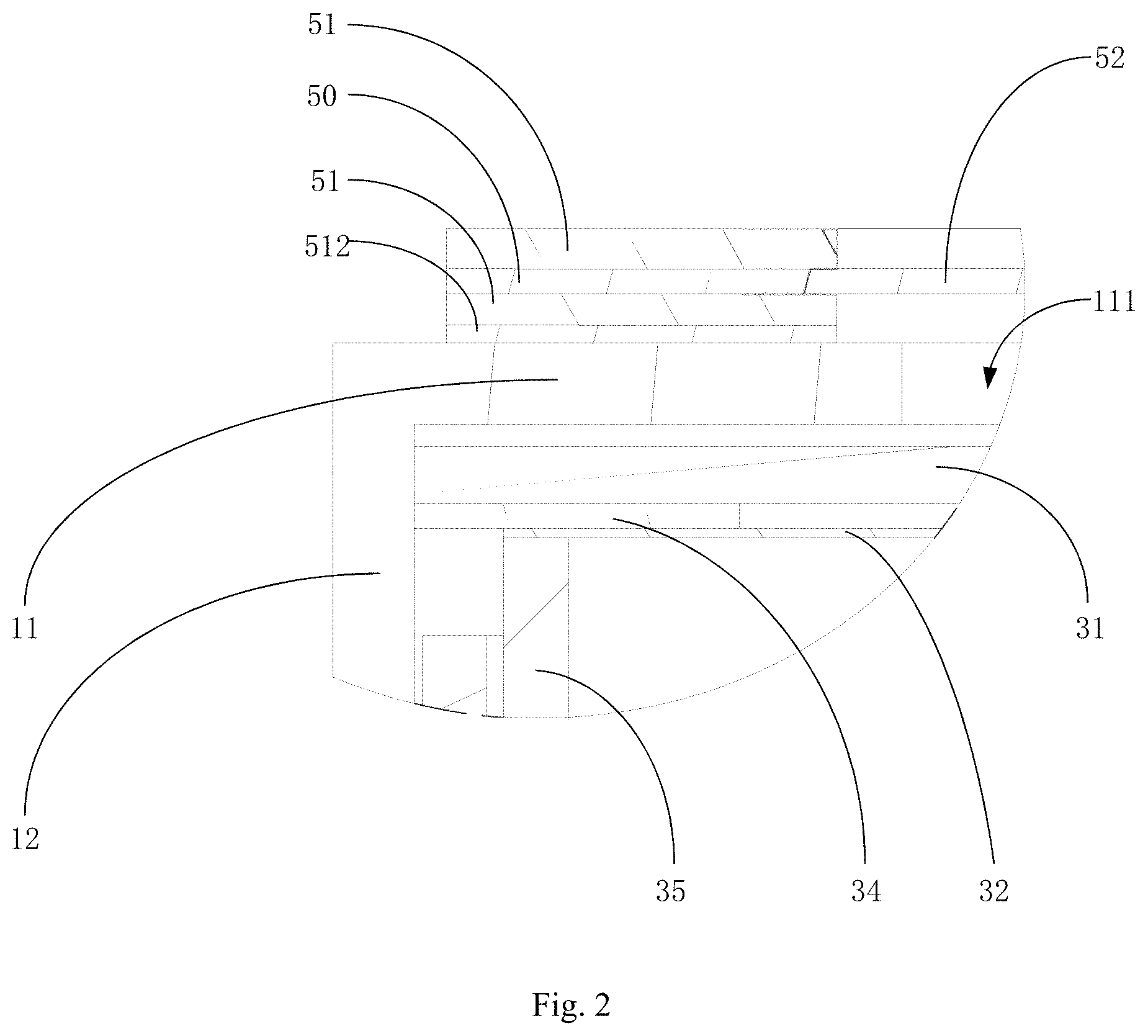
6. The air pressure switch of claim 4, wherein the area enclosed by the sensing area and the inner ring surface forms a circle, wherein the diameter range of the sensing area is 2 mm-3 mm, and the diameter range of the inner ring surface of support element is 2 mm-6 mm.
7. The air pressure switch of claim 6, wherein the diameter of the sensing area is 2.5 mm, and the diameter of inner ring surface of the supporting element is 3 mm-5 mm.
8. The air pressure switch of claim 4, wherein the thickness of the protective film at the elastic deformation region is 0.03 mm-0.5 mm.
9. The air pressure switch of claim 4, wherein the supporting element is integrally formed with the protective film.
10. The air pressure switch of claim 9, wherein the support element is formed on the surface of the protective film facing towards the main body, or the protective film is formed on the inner ring surface of the support element.
11. The air pressure switch of claim 9, wherein: the main body includes a first surface and other surfaces adjacent to the first surface, and other surfaces encircles to form a second outer surface of main body; the sensing area locates on the first surface, and the supporting element and the protective film are sequentially arranged outside the first surface; and the outer ring surface of the supporting element includes a sealing part that is elastically and tightly sleeved on the second outer peripheral surface.
12. The air pressure switch of claim 4, wherein the air pressure switch further includes a compression ring, wherein one end of the compression ring is pressed against the edge of the protective film away from the main body, and the other end is sleeved with the main body, in order to press the edge of the protective film against the main body.
13. The air pressure switch of electronic cigarette as the in claim 4, wherein the side of the supporting member away from the protective film includes an adhesive layer, wherein the supporting element is installed on the main body, and the adhesive layer tightly bonds the outer surface of the main body and the supporting element.
14. The air pressure switch of claim 1, wherein the main body includes an inner cavity, an air vent, and a trigger component in the inner cavity, wherein the trigger component is triggered under negative pressure, wherein the air vent communicates with the outside to form the sensing area, wherein when the outside forms negative pressure, the airflow in the inner cavity is configured to flow out through the air vent.
15. The air pressure switch of claim 14, wherein the trigger component comprises a conductive sheet, a floating diaphragm, and a circuit board that are sequentially arranged from the side close to the air vent to the side far from the air vent, wherein the circuit board electrically connects to the conductive sheet, and the conductive sheet is includes at least one air hole communicating with the air vent, wherein the floating diaphragm contacts with and separates from the conductive sheet under air flow, wherein the conductive sheet is configured to generate an electrical signal.
16. A power supply device for electronic cigarettes, the power supply device comprising: an air pressure switch comprising: a main body that comprises an outer surface and a sensing area, wherein the sensing area is triggered by negative pressure; and a flexible protection film installed on the main body and at least a portion of the outer surface of the main body where the sensing area is provided, wherein a first cavity is formed and enclosed by the protective film and the outer surface of the main body where the sensing area is provided; wherein the protective film deforms away from the main body under an external suction force, so that the airflow in the first cavity can partially flow into the space generated by the deformation of the protective film. wherein the air pressure switch is accommodated in the power supply device and establishes an electrical connection with the power supply device; and a sensing airway communicating with the outside, wherein air pressure switch a side of the air pressure switch with protective film exposes to the sensing airway.
17. The power supply device of claim 16, wherein the air pressure switch is accommodated in the sensing airway, and the side of the air pressure switch with protective film faces the side of responsive airway communicating with outside, wherein the outer peripheral surface of the air pressure switch seal-abuts against the sensing airway.
18. An electronic cigarette comprising: an atomizing device; and a power supply device used to supply power to the atomizing device, wherein the power supply device includes: an air pressure switch that includes a main body that comprises an outer surface and a sensing area, wherein the sensing area is triggered by negative pressure; and a flexible protection film installed on the main body and at least a portion of the outer surface of the main body where the sensing area is provided, wherein a first cavity is formed and enclosed by the protective film and the outer surface of the main body where the sensing area is provided; wherein the protective film deforms away from the main body under an external suction force, so that the airflow in the first cavity can partially flow into the space generated by the deformation of the protective film. wherein the air pressure switch is accommodated in the power supply device and establishes an electrical connection with the power supply device; and a sensing airway communicating with the outside, wherein a side of the air pressure switch with protective film exposes to the sensing airway.
19. The electronic cigarette of claim 18, wherein the atomizing device includes at least one air inlet that communicates with the internal airway of the atomizing device and the sensing airway.
20. The electronic cigarette of claim 18, wherein the atomizing device includes at least two air inlets, wherein the atomizing device is installed in the power supply device, wherein one of the at least two air inlets communicates with outside, wherein an airtight airway is formed between the other air inlet and the sensing airway so that the airflow in the sensing airway only flows out through the air inlet.
Description
CROSS-REFERENCE TO RELATED APPLICATION
[0001] This application claims priority to Chinese Patent Application No. 201920715465.3, filed on May 16, 2019. The disclosure of the foregoing application is incorporated herein by reference in its entirety.
TECHNICAL FIELD
[0002] The present utility model relates to an air pressure switch of electronic cigarette, a power supply device of electronic cigarette using the air pressure switch, and an electronic cigarette using the power supply device.
BACKGROUND
[0003] With the gradual development of the electronic cigarette industry, small electronic cigarettes are getting more and more popular with consumers. In order to reduce the size of product, an air pressure switch is usually used to sense user's suction for triggering, so that the electronic cigarette can atomizes stored tobacco juice into smoke for the user.
[0004] However, the air pressure switch needs to communicate with the suction airway of electronic cigarette, so that it can be triggered when the user smokes. During long time smoking, the stored tobacco juice and the condensed water generated from atomization process will accumulate inside the electronic cigarette cavity. However, a piece of dust-proof cloth is usually provided on the surface of air pressure switch of electronic cigarette, which tends to absorb the tobacco juice and the condensed water, resulting in decrease of sensitivity and even lead to short circuit damage.
SUMMARY
[0005] The main purpose of present utility model is to provide an air pressure switch designed to prevent tobacco juice and condensed water from penetrating into the air pressure switch, resulting in damage of the air pressure switch.
[0006] In order to achieve the above object, the present utility model provides an air pressure switch, comprising a main body; the main body is provided with a sensing area, which will be triggered when said sensing area is under negative pressure. Said air pressure switch further includes a flexible protective film; said protective film is installed on said main body and at least the outer surface of said main body where sensing area is provided is airtight covered, so that a first cavity enclosed by said protective film and said surface of said main body where the sensing area is provided is formed.
[0007] Said protective film deforms away from said main body under the external suction force, so that the airflow in said first cavity can partially flow into the space generated by the deformation of said protective film.
[0008] Preferably, the first cavity is an airtight cavity.
[0009] Preferably, either the protective film or said main body is provided with a supporting member; when said protective film is installed on said main body, two sides of said supporting element are respectively abutted against the outer surface of said main body and the surface of said protective film facing towards the main body, so that said protective film and said main body are arranged at interval.
[0010] Preferably, the supporting element is in a ring shape, and the area enclosed by inner ring surface of said supporting element is larger than or equal to the area of said sensing area, so that the sensing area is accommodated in the area enclosed by the inner annular surface of said supporting element when said protective film is installed on said main body, and the protective film uncovered by said supporting element forms an elastic deformation region.
[0011] Preferably, the area enclosed by inner ring surface of said supporting element is larger than the area of said sensing area.
[0012] Preferably, the area enclosed by the sensing area and said inner ring surface forms a circle; the diameter range of said sensing area is 2 mm-3 mm, and the diameter range of said inner ring surface of supporting element is 2 mm-6 mm.
[0013] Preferably, the diameter of said sensing area is 2.5 mm, and the diameter of inner ring surface of said support is 3 mm-5 mm.
[0014] Preferably, the thickness of protective film at said elastic deformation region is 0.03 mm-0.5 mm.
[0015] Preferably, the supporting element is integrally formed with said protective film.
[0016] Preferably, the supporting element is formed on the surface of said protective film facing towards said main body; or said protective film is formed on the inner ring surface of said supporting element.
[0017] Preferably, said main body is provided with a first surface and other surfaces adjacent to said first surface, and said other surfaces encircles to form a second surface of main body. Said sensing area locates on said first surface, and said supporting element and said protective film are sequentially arranged outside the first surface.
[0018] the outer ring surface of said supporting element is further extendedly provided with a sealing part, and said sealing part is elastically and tightly sleeved on said second outer peripheral surface.
[0019] Preferably, said air pressure switch further includes a compression ring; one end of said compression ring is pressed against the edge of said protective film away from said main body, and the other end is sleeved with said main body, in order to press the edge of said protective film against said main body.
[0020] Preferably, the side of said support member away from said protective film is further provided with an adhesive layer. When said supporting element is installed on said main body, said adhesive layer tightly bonds the outer surface of said main body and said supporting element.
[0021] Preferably, said main body is provided with an inner cavity and an air vent. Said main body is provided with a trigger component in said inner cavity, and said trigger component is triggered under negative pressure; said air vent communicates with the outside to form said sensing area. When the outside forms negative pressure, the airflow in said inner cavity may flow out through said air vent.
[0022] Preferably, said trigger component comprises a conductive sheet, a floating diaphragm, and a circuit board that are sequentially arranged from the side close to said air vent to the side far from said air vent; said circuit board electrically connects to said conductive sheet, and said conductive sheet is provided with at least one air hole communicating with said air vent; said floating diaphragm connects to/separates from said conductive sheet under air flow, so that said conductive sheet can generate electrical signal.
[0023] The present utility model also provides a power supply device of electronic cigarette, including an air pressure switch of electronic cigarette. Said power supply device is provided with a sensing airway communicating with the outside. Said air pressure switch is accommodated in said power supply device and establishes an electrical connection with said power supply device; the side of said air pressure switch with protective film exposes to the sensing airway. Wherein, said air pressure switch includes a main body; said main body is provided with a sensing area, which will be triggered when said sensing area is under negative pressure. Said air pressure switch further includes a flexible protective film; said protective film is installed on said main body and at least the outer surface of said main body where sensing area is provided is airtight covered, so that a first cavity enclosed by said protective film and said surface of sensing area provided by the main body is formed.
[0024] Said protective film deforms away from said main body under the external suction force, so that the airflow in said first cavity partially can flow into the space generated by the deformation of said protective film.
[0025] Preferably, the air pressure switch is accommodated in the sensing airway; a side of said air pressure switch provided with a protective film faces the side of sensing airway communicating with outside; the outer of said air pressure switch seal-abuts against said sensing airway.
[0026] The present utility model further provides an electronic cigarette, including an atomizing device and a power supply device of electronic cigarette; said power supply device is used to supply power to said atomizing device. Wherein, said power supply device of electronic cigarette includes an air pressure switch of electronic cigarette. Said power supply device is provided with a sensing airway communicating with the outside. Said air pressure switch is accommodated in said power supply device and establishes an electrical connection with said power supply device; the side of said air pressure switch with protective film exposes to the inside of sensing airway. Wherein, said air pressure switch includes a main body; said main body is provided with a sensing area, which will be triggered when said sensing area is under negative pressure. Said air pressure switch further includes a flexible protective film; said protective film is installed on said main body and at least the outer surface of said main body where sensing area is provided is airtight covered, so that a first cavity enclosed by said protective film and said surface of sensing area provided by the main body is formed.
[0027] Said protective film deforms away from said main body under the external suction force, so that the airflow in said first cavity partially can flow into the space generated by the deformation of said protective film.
[0028] Preferably, said atomizing device is provided with at least one air inlet, and said at least one air inlet communicates with the internal air circuit of said atomizing device and said sensing airway.
[0029] Preferably, at least one air inlet is directly opposite to the sensing airway of said power supply device.
[0030] Preferably, the atomizing device includes at least two air inlets; when said atomizing device is installed in said power supply device, one of said at least two air inlets communicates with outside, and a closed air channel is formed between the other air inlet and the sensing airway, so that the air flow in said sensing airway can only flow out through said air vent.
[0031] The air pressure switch in the technical solution of present utility model does not need the dust-proof cloth covering outside of sensing area like in traditional air pressure switch, it will effectively prevent tobacco juice and condensed water from being absorbed by the dust-proof cloth which is hard to clean. At the same time, a protective film is provided to airtightly cover the sensing area provided on the main body of air pressure switch, which can effectively prevent accumulation of tobacco juice and condensed water in the sensing area during the long-term use and prevent from penetrating into the air pressure switch through said sensing area, resulting in damage of trigger component. At the same time, said protective film is flexible and forms a first cavity with the side of air pressure switch with sensing area; when the user sucks, the protective film will be attracted and deforms away from said air pressure switch. The space between the deformed protective film and said main body will increase. Since the protective film airtight-covers said sensing area to make the airflow value in said first cavity constant, a negative pressure will be generated to trigger said sensing area when the volume of first cavity increases, making the electronic cigarette work normally.
DESCRIPTION OF DRAWINGS
[0032] For a more complete understanding of the present invention, or the technical schemes in the prior art, the drawings in the embodiments or the description of the prior art are briefly introduced. Obviously, the drawings in the following description are only some embodiments of the present utility model, it will be apparent to those skilled in the art from this disclosure that other drawings may be easily obtained from these drawings without paying any creative effort.
[0033] FIG. 1 is a schematic sectional view of the connection structure of air pressure switch in the present utility model;
[0034] FIG. 2 is a schematic view of local magnification on A in FIG. 1 of the present utility model;
[0035] FIG. 3 is an exploded view of connection structure of air pressure switch in the present utility model;
[0036] FIG. 4 is a schematic cross-sectional view of connection structure of air pressure switch in another embodiment of the present utility model;
[0037] FIG. 5 is a schematic cross-sectional view of connection structure, in which the sealing portion provided by the protective film is sleeved on the main body;
[0038] FIG. 6 is a cross-sectional view of a connection structure of electronic cigarette described in the present utility model.
DEFINITION OF REFERENCE NUMBERS
TABLE-US-00001 [0039] Reference number Name 100 Air pressure switch 10 Main body 11 First surface 111 Air vent 12 Second outer peripheral surface 13 Inner cavity 30 Trigger component 31 Conductive sheet 311 Air hole 32 Floating diaphragm 33 Circuit board 331 Air compensating vent 34 Insulation ring 35 Conductive ring 40 First cavity 50 Protective film 51 Supporting element 511 Sealing part 512 Adhesive layer 52 Elastic deformation region 60 Compressing ring 200 Power supply device 210 Sensing airway 300 Atomizing device 310 Air inlet 320 Heating component
[0040] The realization of the objects, functional characteristics and advantages of the present utility model will be further described in conjunction with the embodiments and with reference to the drawings.
DETAILED DESCRIPTION
[0041] The technical solutions in the embodiments of present utility model will be clearly and completely described as below with reference to drawings in the embodiments of present utility model. Obviously, any described embodiment is only a part of embodiments of present utility model, but not all of them. Based on the embodiments of present utility model, any other embodiment obtained by a person of ordinary skill in the art without any creative efforts shall be within the protection scope of this present utility model.
[0042] It should be noted that any directional indication (such as up, down, left, right, front, and back) in the embodiment of present utility model is only used to explain the relative positional relationship and movement of components in a specific posture (as shown in drawings). If such specific posture changes, the directional indication will change accordingly.
[0043] In addition, the descriptions related to "first", "second", etc. in the present utility model are for descriptive purposes only, and cannot be understood as any indication or implication of its relative importance or implicit indication of the number of technical features. Therefore, any feature defined as "first" or "second" may explicitly or implicitly include at least one of features. In addition, any technical solutions in various embodiments can be combined with each other but must be realized by a person of ordinary skill in the art. When such combination of technical solutions shows conflicts or cannot be achieved, it should be considered as nonexistent and will not be within the protection scope claimed by this present utility model.
[0044] In the present utility model, the terms of "connected" and "fixed" shall be understood in a broad sense unless otherwise specified and defined; for example, "fixed" may be a fixed connection, a detachable connection, or an integral one; It can be a mechanical connection or an electrical connection; it also can be directly connected or indirectly connected through an intermediate medium; it also can be an internal connection of two elements or an interaction relationship between two elements, unless it is clearly defined otherwise. For those of ordinary skill in the art, they can explain specific meanings of above terms in the present invention according to the specific situation.
[0045] The present utility model provides an air pressure switch 100; said air pressure switch 100 is used in electronic cigarettes or other devices triggered by sensing airflow changes. The present utility model takes an electronic cigarette as the example. This electronic cigarette comprises an atomizing device with preloaded tobacco juice 300 and a power supply device 200 providing power for said atomizing device 300. Said power supply device 200 is provided with sensing airway 210; said air pressure switch is installed inside said power supply device 200 and establishes an electrical connection with said power supply device 200. The sensing area of said air pressure switch 100 is at least partially exposed inside said sensing airway 210 for sensing the air pressure inside said sensing airway 210. Said atomizing device 300 is installed in said power supply device 200 and establishes an electrical connection with said power supply device 200. Said atomizing device 300 is provided with at least one air inlet 310; when the atomization device 300 is installed in said power supply device 200, said at least one air inlet 310 communicates with said sensing airway 210. When the user sucks, the airflow inside the sensing airway 210 will flow out and enter the atomizing device 300 through the air inlet 310. At this time, the sensing area of air pressure switch can sense the negative pressure generated by the air's flowing out of the sensing airway 210 and trigger said air pressure switch 100 to transmit the signal to the power supply device 200, which will control the heating element 320 inside the atomizing device 300 to generate heat and atomize pre-stored tobacco juice for users to smoke.
[0046] Refer to FIG. 1 to FIG. 6, the air pressure switch 100 comprises a main body 10; said main body 10 is provided with a sensing area, which will be triggered under negative pressure. It is characterized in that said air pressure switch 100 further comprises a flexible protective film 50; said protective film 50 is installed on said main body 10 and at least the outer surface of said main body 10 where sensing area is provided is airtight covered, so that a first cavity 40 enclosed by said protective film 50 and said surface of sensing area provided by the main body 10 is formed; said protective film 50 deforms away from said main body 10 under the external suction force, so that the airflow in said first cavity 40 can partially flow into the space generated by the deformation of said protective film 50.
[0047] The air pressure switch 100 in the technical solution of present utility model does not need the dust-proof cloth covering outside of the sensing area like in traditional air pressure switch 100, it will effectively prevent tobacco juice and condensed water from being absorbed by the dust-proof cloth which is hard to clean. At the same time, a protective film 50 is provided to airtightly cover the sensing area provided on the main body 10 of air pressure switch 100; which can effectively prevent accumulation of tobacco juice and condensed water in the sensing area during long-term use and prevent from penetrating into the air pressure switch 100 through said sensing area, resulting in the damage of trigger component 30. At the same time, said protective film 50 is flexible and forms a first cavity 40 with the side of air pressure switch 100's main body 10 with sensing area; when the user sucks, the protective film 50 will be attracted and deforms away from said air pressure switch 10's main body 10. The space between the deformed protective film 50 and said main body 10 will increase. Since the protective film 50 airtight-covers the sensing area to make the airflow value in said first cavity 40 constant, a negative pressure will be generated to trigger said sensing area when the volume of first cavity 40 increases, making the electronic cigarette work normally.
[0048] Specifically, as shown in FIG. 1 or FIG. 3, in the embodiment of the present utility model, the main body 10 is provided with an inner cavity 13 and an air vent 111, and said main body 10 is provided with a trigger component 30 in said inner cavity 13. Said air vent 111 communicates with both said inner cavity 13 and the outside, so that the airflow inside the inner cavity 13 may flow out through said air vent 111 and said air vent forms said sensing area on the surface of said main body 10. Said protective film 50 airtight-covers the surface of said main body 10 with said air vent 111. When the user sucks, a negative pressure will be generated by the withdrawn of airflow from inside of said sensing airway 210, so that said protective film 50 can deform away from said main body 10 under the external suction force. At this point, the first cavity 40 between the protective film 50 and the main body 10 increases; the protective film 50 airtightly bonds with the main body 10, so that the volume of air flow in the first cavity 40 and the inner cavity 13 can be constant. When the volume of first cavity 40 increase, the air flow in the inner cavity 13 will compensate into the space generated by the deformation of first cavity 40, decreasing the air pressure. Therefore, the trigger component 30 in the inner cavity 13 is under negative pressure and will be triggered 30.
[0049] Specifically, as shown in FIG. 1 to FIG. 4, in the embodiment of the present utility model, said trigger component 30 comprises a conductive sheet 31, a floating diaphragm 32, and a circuit board 33 that are sequentially arranged in the inner cavity 13 from the side close to said air vent 111 to the side far from said air vent 111; said conductive sheet 31 electrically connects to said circuit board 33 and is provided with at least one air hole 311 communicating with said air vent 111. When the user sucks, the airflow inside the inner cavity 13 will compensate into the first cavity 40 through said air hole 311 and said air vent 111. In the meantime, the floating diaphragm 32 will swing towards said conductive sheet 31 under the action of airflow, then partly contact with or separate from said conductive sheet 31 to transmit electrical signals generated by said conductive sheet 31 to the circuit board 33.
[0050] Specifically, as shown in FIG. 1 to FIG. 3, in the embodiment of the present utility model, the mechanism of said electronic signal generation can be the electrostatic charge generated by friction; for example, said floating diaphragm 32 is an insulation diaphragm and vibrates under the action of airflow to generate electrostatic charge due to the fraction between said floating diaphragm and said conductive sheet 31, and transmit it to the circuit board 33 through conductive sheet 31. At the same time, the principle of said electronic signal generation may also be a conductive electrical loop; for example, the floating diaphragm 32 is a film made of conductive material, and said main body 10 further comprises a conductive ring 35 and a insulation ring 34. Said conductive ring 35 locates between said floating diaphragm 32 and the circuit board 33, and electrically connects to said floating diaphragm 32 and said circuit board 33; said insulation ring 34 locates between said floating diaphragm 32 and said conductive sheet 31 to separate them. When the user sucks, the floating diaphragm 32 deforms under the action of airflow to connect with said conductive sheet 31 at the hollow part in the middle of the insulation ring 34, so that the conductive sheet 31 and the conductive ring 35 can make a loop to generate electrical signal.
[0051] Furthermore, as shown in FIG. 1 or FIG. 4, in the embodiment of the present utility model, in order to facilitate the vibration of floating diaphragm 32, an air compensating vent 331 communicating with the outside is provided on the side of circuit board 33 facing towards said floating diaphragm 32. When the floating diaphragm 32 moves toward the conductive sheet 31 under negative pressure, the external airflow can enter the main body 10 through the air compensating vent 331 to make the floating diaphragm 32 deform or unsymmetrically vibrate. Of course, the location of said air compensating vent 331 is not limited on the circuit board 33; for example, it is on the second outer peripheral surface 12 to compensate air into the inner cavity 31 of main body 10 on the side of floating diaphragm 32 away form said conductive sheet 31. This method is also fall in the protection scope of the present utility model.
[0052] Furthermore, as shown in FIG. 1 to FIG. 4, in the embodiment of present utility model, the protective film 50 should be prevented from tightly contacting with said main body 10, which result in insensitive trigger due to lack of deformation of the protective film 50 during drawing. In this embodiment, a supporting element 51 is provided between said protective film 50 and the main body 10. When the protective film 50 is installed on the main body 10, both sides of said supporting element 51 will abut against the outer surface of said main body 10 and the surface of said protective film 50 facing towards the main body 10 respectively to make a space between the protective film 50 and the main body 10, which will prevent certain friction or electrostatic absorption between these two, resulting in that the protective film 50 cannot trigger said trigger component 30 during suction due to lack of deformation. At the same time, the first cavity 40 formed between said protective film 50 and said main body 10 has a certain original volume for storing a certain amount of air, which makes the protective film 50 more prone to deformation and reduces the effect of temperature on air pressure at the same time.
[0053] Specifically, said trigger component 30 uses model S087 trigger components, and it is a micro-pneumatic sensing component with -400 pa trigger accuracy. To prevent false triggering caused by air pressure changes due to temperature, in this embodiment, a program is installed on the circuit board 33. Said conductive sheet 31 and the floating diaphragm 32 can be used as the sampling ends, and the electric potential or the amount of charge carried by them are collected at a certain time interval and defined as the standard air pressure value, so that the false triggering caused by the expansion of airflow due to the ambient temperature can be effectively prevented.
[0054] Furthermore, said supporting element 51 is a ring shape; the area enclosed by the inner ring surface of supporting element 51 is larger than or equal to the opening area of the air vent 111, so that said air vent 111 is accommodated in the area enclosed by the inner surface of supporting element 51 and the art of protective film covered 50 uncovered by the supporting element 51 can cross the outer side of said air vent 111 to form an elastic deformation region 52 when the protective film 50 is installed on the main body 10. Wherein, because the area enclosed by the inner ring surface of supporting element 51 is larger than or equal to the opening area of said air vent, the supporting element 51 and the protective film 50 completely cover said air vent 111 when the protective film 50 is installed on the main body 10.
[0055] Specifically, to ensure the trigger accuracy, the user can adjust the flexibility of protective film 50 to improve its deformation or design a larger deformation area on the protective film 50 to increase the size of space generated after the deformation. In this embodiment, the elastic deformation region 52 of said protective film 50 is the area enclosed by the inner ring surface of said supporting element 51, so that its trigger accuracy can be further improved due to the larger inner ring surface of said supporting element 51. Furthermore, when the distance between the outer ring surface and the inner ring surface of said supporting element 51 is fixed, the larger said outer ring surface, the larger the area enclosed by said inner ring surface will be. In this embodiment, said outer ring surface and the outer edge of said main body 10 are matched to maximize the space created after deformation of the protective film 50. At the same time, because the circle area is the largest under the same diameter, said sensing area and said inner ring surface of supporting element 51 are all designed as round shape.
[0056] Specifically, said main body 10 is a cylindrical shape and its cross-sectional diameter is 6 mm. The first surface 11 of said main body 10 is provided with said air vent 111 to form said sensing area. The diameter range of air vent 111 is 2 mm-3 mm, and its opening area accounts for one third to one half area of said first surface 11, so that the air flow of inner cavity 13 can quickly flow into the first cavity 40 from the air vent 111 and generate negative pressure to trigger the trigger component 30 when the deformation of the protective film 50 occurs under the action of suction force.
[0057] Specifically, the diameter of said air vent 111 is 2.5 mm; at this time, the distance between said main body 10 and the outer edge of said air vent 111 is 1.75 mm, which will limit the position of the trigger component 30 inside the inner cavity 13 to prevent the internal trigger component 30 from crushing the first surface 11 when the suction force is too large.
[0058] Specifically, in this embodiment, said protective film 50 and said supporting element 51 are made of flexible materials, such as silica gel, and integrated into one piece to facilitate processing and producing. The processing method can be: firstly cut out a base layer matching or larger than the size of first surface 11 of main body 10, then process a groove at the position corresponding to said air vent 111, and its diameter will be larger than or equal to that of said air vent 111; the thickness of bottom wall of the groove should be thin and tends to deform to form the elastic deformation region 52; the outer edge of the groove should be thicker to form the supporting element 51.
[0059] Furthermore, in order to prevent the elastic deformation region 52 from locating at the end of the supporting element 51, which tends to scratch during cleaning, both sides of base layer of said protective film 50 can be provided with grooves simultaneously during production, so that the elastic deformation region 52 forms in the middle of inner ring surface of said supporting element 51 to produce a certain height difference from the outer end of said supporting element 51 to prevent scratch.
[0060] Furthermore, in order to prevent uncompleted covering on the sensing area when the protective film 50 is installed on the main body 10, in this embodiment, the diameter range of inner ring surface of said supporting element 51 is set to 2 mm-6 mm, so that the area enclosed by the inner ring surface of supporting element 51 is larger than or equal to the opening area of said air vent 111, and air vent 111 can be completely surrounded by the inner ring surface of said supporting element 51 when the protective film 50 is installed on the main body 10, which will prevent external airflow from entering the first cavity 40 through the gap between the supporting element 51 and the main body 10, resulting in fail to trigger.
[0061] Furthermore, the thickness of said elastic deformation region is 0.03 mm-0.5 mm, which mainly depends on the elastic deformability of product; at the same time, it also depends on the area of elastic deformation region 52. It can be understood that, when the diameter of elastic deformation region 52 (the inner ring surface of supporting element 51) is small, such as 2-3 mm, larger deformation will be required to trigger said trigger component 30. Therefore, if the specific thickness value matches the strength of material selected for the protective parts, the thinner size of thickness of the elastic deformation region 52, such as 0.03 mm-0.09 mm, can prevent crack when larger deformation occurs. When the diameter of elastic deformation region 52 (the inner ring surface of supporting element 51) is larger, such as 6 mm, at this time, the elastic deformation region 52 can trigger said triggering component 30 under little deformation; therefore, a thicker protective film 50 can be used, such as the protective film 50 with the thickness of 0.2 mm -0.5 mm.
[0062] Specifically, as shown in FIG. 4, the air pressure switch 100 described in the embodiment of the present utility model further comprises a compression ring 60; one end of said compression ring 60 is pressed against the side of said protective film 50 away from the main body 10, and the other end is sleeved with the main body 10 to prevent the protective film 50 from tightly pressing against the first surface 11 of main body 10; at this time, in order to ensure firm compression, the designed distance between the outer ring surface and the inner ring surface of said supporting element 51 is large enough to facilitate the compression of the compression ring 60. For example, in this embodiment, the diameter of said inner ring surface is 3 mm, and the thickness of single side of the supporting element 51 is 1.5 mm, which can ensure compression of said compression ring 60.
[0063] It can be understood that, in practical applications, it is not limited for said protective film 50 to choose the pressing way of compression ring 60 mentioned in above embodiment. For example, as shown in FIG. 5, in other embodiments of present utility model, the definition is: the surface with the air vent of said main body 10 is the first surface 11; said main body 10 and other surfaces adjacent to said first surface 11 form the second outer peripheral surface 12 of the main body 10. In this embodiment, the outer ring surface of said supporting element 51 is provided with an extended sealing part 511; this sealing part 511 and said supporting element 51 are made of flexible materials and integrated into one piece with certain elasticity; the sealing part 511 sleeve connects with the second outer peripheral surface 12 of main body 10 to fix the protection film 50, which is also within the protection scope of present utility model. This fixing method doesn't need the compression ring 60 to tightly press, so the size of inner ring surface of the support ring can be further larger, such as its diameter is 3.6 mm, 4 mm, etc.; at this time, the thickness of elastic deformation region 52 is 0.1 mm or 0.12 mm, which can ensure its better elastic deformability and stronger connection strength to avoid break. As another example, one side of the supporting element 51 away from said protective film 50 can be provided with an adhesive layer 512. When the protective film 50 is installed on the main body 10, the side with the supporting element 51 of the protective film 50 will be tightly pressed on the outer surface of main body 10 to make the supporting element 51 and the surface of main body 10 bond tightly, and complete the installation. This method of bonding makes installation much easier and can effectively prevent air leakage due to the gap between them.
[0064] The present utility model further provides a power supply device 200 of electronic cigarette; the power supply device 200 comprises said air pressure switch 100 and executes the corresponding command when the sensor of said power supply device 200 responding to said air pressure switch 100 is triggered. Refer to the foregoing embodiments for the specific structure of air pressure switch 100. Since the electronic cigarette adopts all technical solutions described in the foregoing embodiments, it has at least all benefits brought by technical solutions of foregoing embodiments. The effects will not be repeated here.
[0065] Specifically, as shown in FIG. 6, in the embodiment of present utility model, said air pressure switch 100 is provided with a sensing airway 210 communicating with the outside; said air pressure switch 100 is accommodated in said power supply device 200, and the circuit board 33 inside said air pressure switch 100 establishes an electrical connection with said power supply device 200, so that said trigger component 30 can transmit control signals to said power supply device 200 through said circuit board 33 when said trigger component 30 senses the negative pressure. The side of said air pressure switch 100 with protective film 50 faces towards the side of said sensing airway 210 communicating with the outside, so that the protective film 50 can deform under the action of suction force. At the same time, in order to ensure the trigger accuracy, said air pressure switch 100 can be installed in the sensing airway 210, and the outer surface of said air pressure switch 100 is airtightly abutted against the inner wall of sensing airway 210, so that the air flow cannot be sucked out from the gap between the air pressure switch 100 and the induction airway 210 when the user sucks, which will avoid small suction force on the protective file 50.
[0066] The present utility model further provides an electronic cigarette, which comprises an atomizing device 300 and a power supply device 200; said atomizing device 300 is provided with at least one air inlet 310, and said at least one air inlet 310 communicates with the inside of said atomizing device 300 and said sensing airway 210. When the user sucks, the airflow in the sensing airway 210 can be sucked out to trigger said air pressure switch 100.
[0067] Specifically, in order to ensure the airflow in the sensing airway 210 is sucked into said air inlet 310 in time, in this embodiment, said at least one air inlet 310 is directly opposite to the sensing airway 210, so that the airflow in said sensing airway 210 can be preferentially sucked out when the user sucks, thereby increasing the sensitivity of trigger.
[0068] Specifically, in this embodiment, said atomizing device 300 further includes multiple air inlets 310. For example, the atomizer is provided with two air inlets 310; one of air inlets 310 is provided on the side of said atomizing device 300 and communicates with the outside, which is mainly used to provide working airflow for atomization inside the atomizer. Another air inlet 310 can be provided at the bottom of atomizing device 300 and directly face towards the sensing airway 210 provided on said power supply device 200, so that the airflow in the sensing airway 210 facing towards the air inlet 310 can be sucked out to generate a suction force on the protective film 50 of said pneumatic airway switch when the user sucks and make it deform to produce negative pressure for triggering the sensing area.
[0069] Specifically, in order to prevent the air inlet 310 directly facing said sensing airway 210 from sucking the airflow from other place as well as from the sensing airway 210, resulting in less suction force in the sensing airway 210 and lack of triggering to said air pressure switch 100, in this embodiment, a sealed air guiding tube is used. One end of tube is inserted into the air inlet 310, and the other end is inserted into the sensing airway 210, so that the suction force generated by the air inlet 310 when the user sucks can only suck out the air flow through the sensing airway 210 to ensure the trigger sensitivity of air pressure switch 100.
[0070] It can be understood that, in practical applications, it is not limited to use sealed air guiding tube inserted into the air inlet 310 and the sensing airway 210 respectively. For example, the outer edge of sensing airway 210 or one of air inlets 310 can be in a higher level, so that the outer edges of air inlets 310 and sensing airway 210 are abutted against each other when the atomizing device 300 is installed in the power supply device 200 to ensure the airflow sucked into the air inlet 310 is only from said sensing airway 210. This method is also fall in the protection scope of present utility model.
[0071] The above is only the preferred embodiment of present utility model, and is not intended to limit the patent scope of the utility model. Any equivalent structural transformation made by using contents of the description and drawings of present utility model, or directly/indirectly used in other relevant technical fields under the inventive concept of the present utility model shall be included within the protection scope of patent of the present utility model.
* * * * *
D00000
D00001
D00002
D00003
D00004
D00005
D00006
XML
uspto.report is an independent third-party trademark research tool that is not affiliated, endorsed, or sponsored by the United States Patent and Trademark Office (USPTO) or any other governmental organization. The information provided by uspto.report is based on publicly available data at the time of writing and is intended for informational purposes only.
While we strive to provide accurate and up-to-date information, we do not guarantee the accuracy, completeness, reliability, or suitability of the information displayed on this site. The use of this site is at your own risk. Any reliance you place on such information is therefore strictly at your own risk.
All official trademark data, including owner information, should be verified by visiting the official USPTO website at www.uspto.gov. This site is not intended to replace professional legal advice and should not be used as a substitute for consulting with a legal professional who is knowledgeable about trademark law.