Driver Assistance System Of A Forage Harvester
HEITMANN; Christoph ; et al.
U.S. patent application number 16/856318 was filed with the patent office on 2020-11-19 for driver assistance system of a forage harvester. This patent application is currently assigned to CLAAS Selbstfahrende Erntemaschinen GmbH. The applicant listed for this patent is CLAAS Selbstfahrende Erntemaschinen GmbH. Invention is credited to Markus BRUNE, Frederic FISCHER, Christoph HEITMANN, Jochen HUSTER, Dennis NEITEMEIER, Bjoern STREMLAU.
| Application Number | 20200359563 16/856318 |
| Document ID | / |
| Family ID | 1000004807600 |
| Filed Date | 2020-11-19 |


| United States Patent Application | 20200359563 |
| Kind Code | A1 |
| HEITMANN; Christoph ; et al. | November 19, 2020 |
DRIVER ASSISTANCE SYSTEM OF A FORAGE HARVESTER
Abstract
A driver assistance system of an agricultural work machine constructed as forage harvester, wherein the agricultural work machine comprises a header for gathering crop, a chopping device having a chopping drum and chopping knives for comminuting the crop, and a monitoring device operable to generate a signal containing information about the wear status of the respective chopping knife and/or about the distance of the cutting edge of a chopping knife from a shear bar. This information is compared with a reference value, and the agricultural work machine has activation devices for activating and deactivating a knife grinding process and means for change of position of the shear bar. The monitoring device is integrated in the driver assistance system so that the driver assistance system automatically detects when a knife grinding process or a change of position of the shear bar must be activated or deactivated.
| Inventors: | HEITMANN; Christoph; (Warendorf, DE) ; NEITEMEIER; Dennis; (Lippetal, DE) ; BRUNE; Markus; (Harsewinkel, DE) ; HUSTER; Jochen; (Guetersloh, DE) ; STREMLAU; Bjoern; (Recke, DE) ; FISCHER; Frederic; (Arnsberg, DE) | ||||||||||
| Applicant: |
|
||||||||||
|---|---|---|---|---|---|---|---|---|---|---|---|
| Assignee: | CLAAS Selbstfahrende Erntemaschinen
GmbH Harsewinkel DE |
||||||||||
| Family ID: | 1000004807600 | ||||||||||
| Appl. No.: | 16/856318 | ||||||||||
| Filed: | April 23, 2020 |
| Current U.S. Class: | 1/1 |
| Current CPC Class: | A01F 29/095 20130101; A01D 43/085 20130101; G01B 7/14 20130101; A01D 41/1271 20130101; G01B 7/293 20130101; A01F 29/22 20130101 |
| International Class: | A01D 43/08 20060101 A01D043/08; A01D 41/127 20060101 A01D041/127; A01F 29/09 20060101 A01F029/09; A01F 29/22 20060101 A01F029/22; G01B 7/14 20060101 G01B007/14; G01B 7/293 20060101 G01B007/293 |
Foreign Application Data
| Date | Code | Application Number |
|---|---|---|
| May 16, 2019 | DE | 10 2019 112 968.0 |
| May 16, 2019 | DE | 10 2019 112 973.7 |
| Jul 1, 2019 | DE | 10 2019 112 965.6 |
Claims
1. A driver assistance system of an agricultural work machine constructed as forage harvester having a header for gathering crop and a chopping device comprising a chopping drum and chopping knives associated with the chopping drum for comminuting the crop, and activation devices for activating and deactivating a knife grinding process and for changing a position of the shear bar, the driver assistance system comprising: a monitoring device that is operable to generate a signal which contains information about a wear status of a respective one of the chopping knives or about a distance of a cutting edge of one of the chopping knives from a shear bar, wherein the driver assistance system is configured to compare information about the wear status of the chopping knives or about the distance of the cutting edge from the shear bar with a reference value in each instance, and wherein the monitoring device is integrated in the driver assistance system in such a way that the driver assistance system automatically detects when a knife grinding process must be activated or deactivated or a change of position of the shear bar is to be activated or deactivated.
2. The driver assistance system of an agricultural work machine constructed as forage harvester according to claim 1, wherein the driver assistance system is configured to activate or deactivate the knife grinding process or the change of position of the shear bar, or generates a notification for an operator of the agricultural work machine to activate or deactivate the knife grinding process or the change of position of the shear bar.
3. The driver assistance system of an agricultural work machine constructed as forage harvester according to claim 1, wherein the driver assistance system is configured such that signals generated by the monitoring device which contain information about the wear status of the respective chopping knife or about the distance of the cutting edge of a chopping knife from a shear bar are converted into an actual cutting sharpness value and an actual distance value of the shear bar, and the respective actual value is compared with the stored associated reference value, and when the respective actual value lies below a sharp knife reference value or above the reference distance value, the knife grinding process or the change of position of the shear bar is activated.
4. The driver assistance system of an agricultural work machine constructed as forage harvester according to claim 3, wherein the driver assistance system is configured such that signals which are generated by the monitoring device and which contain information about the wear status of the respective chopping knife or about the distance of the cutting edge of a chopping knife from a shear bar are converted into an actual cutting sharpness value and an actual distance value of the shear bar, and the respective actual value is compared with the stored associated reference value, and when the actual value reaches or lies above a sharp knife reference value or when the actual value reaches or lies below the reference distance value, the knife grinding process or the change of position of the shear bar is deactivated.
5. The driver assistance system of an agricultural work machine constructed as forage harvester according to claim 3, wherein the driver assistance system is configured such that the sharp knife reference value and the reference distance values of the shear bar can be changed depending on the type of crop.
6. The driver assistance system of an agricultural work machine constructed as forage harvester according to claim 1, wherein the monitoring device monitors the cutting sharpness or the wear status or a magnitude of a cutting gap for each chopping knife.
7. The driver assistance system of an agricultural work machine constructed as forage harvester according to claim 1, wherein the driver assistance system is configured to determine a radius of the chopping drum from distance signals generated by the monitoring device.
8. The driver assistance system of an agricultural work machine constructed as forage harvester according to claim 1, wherein the driver assistance system is configured to determine a quantity of chopping knives positioned on a chopping drum from signals generated by the monitoring device, and a configuration of the chopping drum is brought about automatically in the driver assistance system.
9. The driver assistance system of an agricultural work machine constructed as forage harvester according to claim 1, wherein the driver assistance system is configured such that a product feed-dependent wear status is inferred from signals generated by the monitoring device, and steps are derived which bring about a product feed that reduces wear.
10. The driver assistance system of an agricultural work machine constructed as forage harvester according to claim 9, wherein the derived steps contain a change of one or more parameters of the header for receiving crop and/or gathering and pre-compacting rollers arranged downstream of the header.
11. The driver assistance system of an agricultural work machine constructed as a forage harvester according to claim 1, wherein the monitoring device comprises a detection arrangement for detecting the wear status of a respective chopping knife of the chopping device, wherein the drum is a revolving chopping drum and wherein there is at least one shear bar which cooperates with the chopping knives, wherein the detection arrangement comprises at least one sensor arrangement which has a magnetic exciter arrangement and a flux conducting device magnetically coupled thereto, wherein the sensor arrangement provides a pole arrangement which forms at least one magnetic pole with a pole surface for conducting magnetic flux, wherein the sensor arrangement is positioned such that at least a portion of the chopping knives passes the pole arrangement during a rotation of the chopping drum, the chopping knife passing the pole arrangement forms an air gap arrangement with at least one air gap with respect to the pole arrangement, and at least one magnetic circuit excited by the exciter arrangement is accordingly closed via the respective chopping knife, wherein the detection arrangement has a measuring arrangement and an evaluating unit, wherein the measuring arrangement is configured to detect at least one measured magnetic value pertaining to the magnetic flux in at least one magnetic circuit excited by the exciter arrangement, and the evaluating unit is configured to determine the wear status of the respective chopping knife from the at least one detected measured value.
12. The driver assistance system of an agricultural work machine constructed as forage harvester according to claim 11, wherein the voltage induced when the chopping knife arrangement passes the sensor arrangement forms the measured magnetic value, and the detection arrangement is configured to determine the induced voltage and record it as a voltage signal, the evaluating unit is configured to resolve the voltage signal into its frequency components by means of frequency analysis in which frequency components are separated into frequency components of a fundamental oscillation and into frequency components of a superposed oscillation which cause signal distortion, wherein the separated frequency components of the superposed oscillation which cause a signal distortion are inverse-transformed in a time domain, and a measurement for the wear status or cutting sharpness of one of the chopping knives is derived from the inverse-transformed frequency components of the superposed oscillation.
13. The driver assistance system of an agricultural work machine constructed as forage harvester according to claim 11, wherein the at least one sensor arrangement is positioned at a circumference of the chopping drum such that every chopping knife of the chopping drum is detected by means of a sensor arrangement, wherein right-hand-side and left-hand-side chopping knife arrangements are associated with the chopping drum, and at least one sensor arrangement is associated with each of these chopping knife arrangements.
14. The driver assistance system of an agricultural work machine constructed as forage harvester according to claim 11, wherein a plurality of induction sensors are associated with each sensor arrangement, and each induction sensor is configured to generate a voltage signal, wherein each of the generated voltage signals is analyzed separately, and wherein a plurality of voltage signals, or all of the voltage signals, of a detected chopping knife are combined to form one or more voltage signals prior to an analysis.
15. The driver assistance system of an agricultural work machine constructed as forage harvester according to claim 14, wherein the frequency analysis of the voltage signal is carried out by means of Fourier analysis to classify the respective voltage signal into frequency components of a fundamental oscillation and frequency components of a superposed oscillation which cause signal distortions, and wherein the frequency components representing the fundamental oscillation are not taken into account in the derivation of the wear status or of the cutting sharpness of the respective chopping knife.
16. The driver assistance system of an agricultural work machine constructed as forage harvester according to claim 15, wherein an amplitude of the respective voltage signal of the frequency components causing a signal distortion forms a measurement for assessing the wear status and/or the cutting sharpness of the respective chopping knife.
17. The driver assistance system of an agricultural work machine constructed as forage harvester according to claim 16, wherein the assessment of the cutting sharpness or wear status is effected by means of evaluation criteria selected from the group consisting of grinding surface length of the respective chopping knife, roundness of a chopping knife tip, general knife wear, camber of the chopping knife and relative distance of the shear bar from the chopping knife.
Description
CROSS-REFERENCE TO RELATED APPLICATIONS
[0001] This application claims priority under 35 USC 119 of German Application No. DE 10 2019 112 968.0, filed on May 16, 2019, German Application No. DE 10 2019 112 973.7, filed on May 16, 2019 and German Application No. DE 10 2019 112 965.6, filed on Jul. 1, 2019, the disclosure of which is herein incorporated by reference.
BACKGROUND OF THE INVENTION
[0002] The invention is directed to a driver assistance system of an agricultural work machine constructed as forage harvester for monitoring the wear status of chopping knives.
[0003] A sensor arrangement which detects the revolving knives of a chopping drum arrangement by means of inductive sensors and derives a wear status of the chopping knives from the determined magnetic flux is known from DE 10 2017 103 537. Wear is determined from the induced voltage.
[0004] In addition, a similar cutting sharpness detection device is known, inter alia, from EP 1 522 214. In this case, optical sensors such as camera systems, lasers and near infrared sensors are used as detection devices.
[0005] Optical sensors have the problem that the cutting edge analysis is made more difficult by the high revolving speeds of the chopping knives, which often leads to poor-quality analysis results. On the other hand, the analysis of an induced voltage is influenced appreciably less by the high revolving speeds of the chopping knives to be detected. However, the evaluating process which is exclusively directed to the induced voltage does not always lead to a sufficiently accurate estimation of a wear status.
[0006] Further, a forage harvester outfitted with a driver assistance system is known from DE 10 2018 106 915.4. The work elements of the forage harvester are constructed as automatic adjusting means which are controllable by the driver assistance system in such a way that the work parameters of the forage harvester can be optimized without necessitating the involvement of the operator of the forage harvester in this process. This has the effect in particular that the operator need no longer personally monitor the work quality of the forage harvester. The drawback of this is that the known driver assistance system does not remove the operator of the agricultural work machine from the process of grinding the chopping knives.
SUMMARY OF THE INVENTION
[0007] Therefore, it is the object of the invention to avoid the disadvantages of the prior art described above and in particular to enable a driver assistance system to monitor the wear status of chopping knives.
[0008] This object is met according to the invention by an agricultural work machine constructed as forage harvester that comprises a monitoring device integrated in the driver assistance system in such a way that the driver assistance system automatically detects when a knife grinding process must be activated or deactivated and/or a change of position of the shear bar is to be activated or deactivated. In this way, it is ensured that a knife grinding process and a change of position of the shear bar is not dependent on monitoring by or judgment of the operator, which has the effect in particular that the knife grinding process is limited to the necessary extent.
[0009] In an advantageous configuration of the invention, the driver assistance system activates or deactivates the knife grinding process and/or the change of position of the shear bar automatically or generates a notification for an operator of the agricultural work machine to activate or deactivate the grinding process and/or the change of position of the shear bar so that the operator is completely relieved of monitoring tasks with regard to the cutting sharpness of the chopping knives. Further, the driver of the machine is notified about the state of the knives.
[0010] In an advantageous further development of the invention, it is ensured that the chopping knives are always kept in a sharp state which, in addition to high chopping quality, results in optimal fuel consumption in that the signals generated by the monitoring device which contain information about the wear status of the respective chopping knife and/or about the distance of the cutting edge of a chopping knife from a shear bar are converted into an actual cutting sharpness value and an actual distance value of the shear bar, and the respective actual value is compared with the stored associated reference value, and when the respective actual value lies below the "sharp knife" reference value or above the reference distance value, the knife grinding process or the change of position of the shear bar is activated.
[0011] In order to limit the grinding process to the necessary extent, the signals which are generated by the monitoring device and which contain information about the wear status of the respective chopping knife and/or about the distance of the cutting edge of a chopping knife from a shear bar are converted into an actual cutting sharpness value and an actual distance value of the shear bar, and the respective actual value is compared with the stored associated reference value, and when the actual value reaches or lies above the "sharp knife" reference value or when the actual value reaches or lies below the reference distance value, the knife grinding process or the change of position of the shear bar is deactivated.
[0012] In order that crop-dependent effects on the wear of the chopping knives can be better taken into account, the "sharp knife" reference value and the reference distance values of the shear bar can be changed depending on the type of crop.
[0013] A high precision is achieved in the monitoring of cutting sharpness in that the monitoring device monitors the cutting sharpness and/or the wear status and/or the magnitude of the cutting gap for each chopping knife.
[0014] In view of the fact that an irregular product flow to the chopping drum to the chopping drum substantially influences the wear of the chopping knives, a radius of the chopping drum is determined from the distance signals generated by the monitoring device. This has the effect that an irregular wear and, therefore, an irregular product feed to the chopping drum can be inferred from the change of radius of the chopping drum. In this connection, it is also advantageous when a product feed-dependent wear status is inferred from the signals generated by the monitoring device, preferably the derived change of the radius of the chopping drum, and steps are derived which bring about a product feed that reduces wear. In the simplest case, the wear-reducing product feed can be brought about in that the derived steps contain a change of one or more parameters of the header for receiving crop and/or gathering and pre-compacting rollers arranged downstream of the header.
[0015] It is further ensured that the operator is substantially relieved from configuring effort in that the quantity of chopping knives positioned on a chopping drum is determined from the signals generated by the monitoring device, and the configuration of the chopping drum is brought about automatically in the driver assistance system.
[0016] It is ensured in a simple manner that the wear status of each chopping knife can be determined individually in that the detection arrangement for detecting a wear status of a chopping knife arrangement of a chopping device provided for processing a product flow is constructed as an inductive detection arrangement, and the voltage induced when a chopping knife arrangement passes over the sensor arrangement forms the measured magnetic value, and the detection arrangement determines the induced voltage and records it as a voltage signal, and an evaluating unit determines the wear status of the respective chopping knife from the at least one detected measured value.
[0017] In a further advantageous configuration of the invention, the detection of the wear status of chopping knives can be improved through simple measures in that the voltage signal is resolved into its frequency components in the evaluating unit by means of frequency analysis, and the frequency components are separated into frequency components of a fundamental oscillation and into frequency components of a superposed oscillation which cause signal distortion, and the separated frequency components of the superposed oscillation which cause a signal distortion are inverse-transformed in the time domain, and a measurement for the wear status and/or the cutting sharpness of a chopping knife is derived from the inverse-transformed frequency components of the superposed oscillation.
[0018] A sensor arrangement or the plurality of sensor arrangements are positioned at the circumference of the chopping drum such that every chopping knife of the chopping drum is detected by means of a sensor arrangement, it is ensured that each chopping knife positioned at the circumference of the chopping drum can be detected. This effect is also achieved in a further advantageous configuration in that right-hand-side and left-hand-side chopping knife arrangements are associated with the chopping drum and at least one sensor arrangement is associated with each of these chopping knife arrangements.
[0019] A high-resolution and therefore very precise analysis of the wear status and knife sharpness is achieved in that a plurality of induction sensors, preferably five induction sensors, are associated with each sensor arrangement and each induction sensor generates a voltage signal, and each of the generated voltage signals is preferably analyzed separately and, further preferably, a plurality of voltage signals, or all of the voltage signals, of a detected chopping knife are combined to form one or more voltage signals prior to an analysis.
[0020] By means of Fourier analysis, the respective voltage signal is classified into frequency components of a fundamental oscillation and frequency components of a superposed oscillation which cause signal distortions, and the frequency components representing the fundamental oscillation are not taken into account in the derivation of the wear status and/or of the cutting sharpness of the respective chopping knife. In this way, it is ensured that only those frequency components which change significantly depending on the wear of the chopping knives and which are therefore suitable as indicators for qualifying wear or knife sharpness are taken into account. A particularly advantageous configuration results in this respect when the amplitude of the respective voltage signal of the frequency components causing a signal distortion is taken into account because this amplitude is a measurement for assessing the wear status and/or cutting sharpness of the respective chopping knife and can be determined in a simple manner.
[0021] A particularly efficient monitoring of the wear status or chopping knife sharpness, particularly with respect to different types of wear occurring on the chopping knives, is made possible when the assessment of the cutting sharpness is effected by means of evaluation criteria, and the evaluation criteria are one or more of the evaluation criteria comprising "grinding surface length of the respective chopping knife", "roundness of the chopping knife tip", "general knife wear" and/or "camber of the chopping knife" or "relative distance of the shear bar from the chopping knife".
BRIEF DESCRIPTION OF THE DRAWINGS
[0022] Further advantageous configurations are the subject of further subclaims and are described in the following with reference to an embodiment example shown in the figures. In the drawings:
[0023] FIG. 1 shows a forage harvester with cutting sharpness detection device according to the invention;
[0024] FIG. 2 shows a detailed view of the forage harvester according to FIG. 1 with cutting sharpness detection device according to the invention;
[0025] FIG. 3 shows a detailed view of the inductive sensor arrangement;
[0026] FIG. 4 shows a schematic view of the frequency analysis according to the invention;
[0027] FIG. 5 shows a detailed view of the frequency analysis according to the invention;
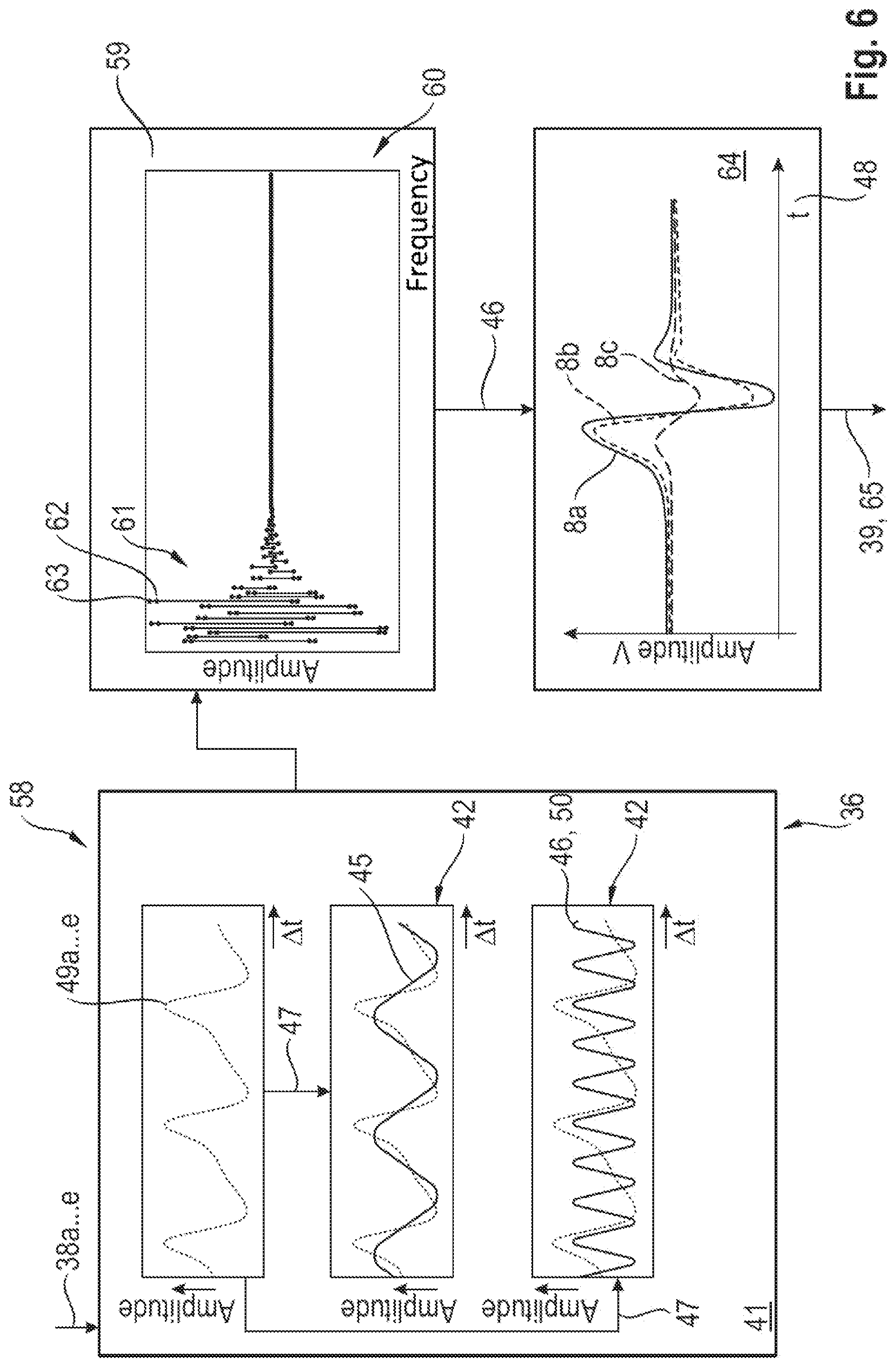
[0028] FIG. 6 shows a further detailed view of the frequency analysis according to the invention;
[0029] FIG. 7 shows a schematic view of a use of the frequency analysis according to the invention;
[0030] FIG. 8 shows a schematic view of the driver assistance system according to the invention; and
[0031] FIG. 9 shows a detailed view of the driver assistance system according to the invention referring to FIG. 8.
DETAILED DESCRIPTION OF THE EMBODIMENTS
[0032] FIG. 1 schematically shows an agricultural work machine 1 which is constructed as a forage harvester 2 and which receives a harvesting header 3 in the front area thereof. Gathering and pre-compacting rollers 4 which accept the crop flow 5 coming from the harvesting header 3, compress it and transfer it to a chopping device 6 in the rear area is associated with the header 3 in the rear area thereof. In a manner to be described further, the chopping device 6 comprises a chopping drum 7 which is outfitted with chopping knives 8 of a chopping knife arrangement 9. In the feed-in area 10 of the chopping drum 7, the revolving chopping knives 8 are moved past a shear bar 11 by means of which the crop flow 5 to be comminuted is conveyed. In the rear area of the chopping drum 7, the comminuted crop 5 is then transferred either to an after-comminution device 13 constructed as a so-called cracker 12 or directly to an after-acceleration device 14. While the after-comminution device 13 further comminutes the grain constituents of the crop flow 5, e.g., corn kernels, the after-acceleration device 14 accelerates the crop flow 5 such that this crop flow 5 can be moved through a deflector 15 and exit from the forage harvester 2 at the end in the area of a deflector flap 16 and can be transferred to a transport vehicle, not shown. Further, a knife grinding device 17 which is known per se and therefore need not be described in detail is associated with the chopping drum 7 at the circumference. The grinding stone 18 of the knife grinding device 17 is movable horizontally over the width of the chopping drum 7 such that every chopping knife 8 positioned at the circumference of the chopping drum 7 can be ground. An activation device 19 which will be described more fully is associated with the knife grinding device 17 for purposes of activating or deactivating the knife grinding process.
[0033] According to FIG. 2, the chopping knife arrangement 9 comprises right-hand-side and left-hand-side chopping knife arrangements 9a, 9b. Each chopping knife arrangement 9a, 9b comprises a plurality of chopping knives 8 positioned oblique to the rotational axis 20 of the chopping drum 7 at the circumference of the chopping drum 7. The chopping drum 7 is sheathed on the underside by a drum base 21 preferably comprising stainless steel. At the upper side, the chopping drum 7 is enclosed by a rear drum wall 22 which likewise preferably comprises stainless steel. The sensor arrangement 23 according to the invention which will be described in more detail later can be positioned either at the rear drum wall 22 according to the embodiment example shown in FIG. 2 or at the drum base 21. It is also conceivable that a sensor arrangement 23 is arranged both at the drum base 21 and the rear drum wall 22 at the same time. Regardless of the specific position, at least two sensor arrangements 23a, 23b are associated with every chopping drum 7 in such a way that one of the sensor arrangements 23a, 23b is associated in each instance with the associated chopping knife arrangement 9a, 9b, respectively. Each sensor arrangement 23a, 23b completely covers the cutting edge 24 of the respective chopping knife 7 so that each cutting edge 24 can be detected over its entire length by the respective sensor arrangement 23a, 23b. Further, it lies within the scope of the invention that the respective sensor arrangement 23a, 23b is positioned either parallel to the rotational axis 20 of the chopping drum 7 or parallel to the cutting edge 24 of the chopping knives 8 at the drum base 21 and/or rear drum wall 22. The view at lower right in FIG. 2 shows the possible orientations of the sensor arrangements 23a, 23b depicted individually merely by way of example. All of the sensor arrangements 23a, 23b are preferably positioned either parallel to the rotational axis 20 of the chopping drum 7 or parallel to the cutting edge 24 of the chopping knives 8. In the depicted embodiment example, the sensor arrangements 23a, 23b are constructed as induction sensors 25 to be described more fully in the following. Each sensor arrangement 23 comprises one or more magnetic exciter arrangements 26 and, in each instance, a pole arrangement 27 cooperating with the latter.
[0034] FIG. 3 depicts some characteristics of the sensor arrangements 23a, 23b. The further details of the sensor arrangements are given in DE 10 2017 103 537 A1, the disclosure of which is hereby incorporated by reference in its entirety herein. The detection arrangement 28 according to the invention for detecting a wear status of a chopping knife arrangement 9a, 9b comprises a plurality of sensor arrangements 23a, 23b, preferably for each chopping knife arrangement 9a, 9b. Every sensor arrangement 23a, 23b is formed by a plurality of magnetic exciter arrangements 26 which are coupled with a flux conducting device 29. The respective sensor arrangement 23a, 23b provides a pole arrangement 27 which forms at least one magnetic pole 30, preferably five magnetic poles 30, with a pole surface 31 in each instance for conducting magnetic flux. During a rotation of the chopping drum 7, a chopping knife 8 passes the respective pole arrangement 27, and the chopping knife 8 passing the pole arrangement 27 forms an air gap arrangement 32 with at least one air gap 33 with respect to the pole arrangement 27, and at least one magnetic circuit 34 excited by the exciter arrangement 26 is accordingly closed via the respective chopping knife 8. The detection arrangement 28 further has a measuring arrangement 35 and an evaluating unit 36. In a manner which will be described more fully later, the measuring arrangement 35 detects at least one measured magnetic value 37 pertaining to the magnetic flux, preferably an induced voltage 38 in at least one magnetic circuit 34 excited by the exciter arrangement 26, and the evaluating unit 36 determines the wear status 39 of the respective chopping knife 8 from the at least one detected measured value 37.
[0035] Details of the measuring device will now be described referring to FIG. 4. During operation of the chopping drum 7, the chopping knives 8 are guided past the respective sensor arrangement 23a, 23b according to the rotational direction 40 of the chopping drum 7. Owing to the virtually non-magnetic properties of the rear drum wall 22 or of the drum base 21 which preferably comprises stainless steel, the magnetic circuits 34 formed by adjacent magnetic poles 30 penetrate the chopping knife 8 passing over the sensor arrangement 23a, 23b, respectively. In the depicted embodiment example, four magnetic circuits 34 which penetrate the respective chopping knife in four sections L1 to L4 are formed between the five poles 30. For each of these sections L1 to L4, a voltage 38, i.e., the measured magnetic value 37, is induced in the measuring arrangement 35 associated with each section L1 to L4. The evaluating unit 36 associated with the detection arrangement 28 determines and records the section-by-section induction voltage 38a-e in each instance. In this respect, it lies within the scope of the invention that the respective sensor arrangement 23 has more or less than the disclosed five magnetic poles 30 so that there can also be more or less than five induced voltages 38a-e. It also lies within the scope of the invention that the voltage signals 38a-e can be combined to form one or more voltage signals 38 for each chopping knife 8 detected.
[0036] The respective voltage signal 38a . . . e is converted in the evaluating unit 36 into a voltage signal 49a . . . e which can be further processed. This voltage signal 49a . . . e which can be further processed is formed in such a way that the induced voltage 38, i.e., the reference value 38 of the induced voltage, is initially determined for a sharp, unworn chopping knife 8, the induction voltage 38a . . . e which changes contingent on wear is then determined during the operation of the chopping knife 8 and, lastly, the voltage signals 49a . . . e which can be further processed are determined from the difference of the wear-dependent change in induction voltage 38a . . . e minus the reference value 38 of the induced voltage of an unworn chopping knife 8.
[0037] The respective voltage signals 49a . . . e is then resolved into its frequency components 42, preferably oscillation period or phase 43 and amplitude 44, in the evaluating unit 36 in a manner known per se by means of frequency analysis 41, preferably by means of Fourier analysis 47. In doing so, the respective induced voltage signal 49a . . . e is separated into frequency components 42 of a fundamental oscillation 45 and into frequency components 42 of a superposed oscillation 46 which cause signal distortions. The separated frequency components 42 causing a signal distortion, i.e., the so-called superposed oscillation 46, are then inverse-transformed in the time domain 48 in a manner to be described more fully later and, lastly, a measurement for the cutting sharpness, i.e., the wear status 39, of a chopping knife 8 is derived from the inverse-transformed frequency components 42 in a manner which will likewise be described more fully later.
[0038] The frequency analysis 41 carried out according to the invention by the evaluating unit 36 is shown schematically in detail in FIG. 5. The voltage signal 49a-e derived in each instance from the induced voltage 38a-e is initially derived in the manner described above. The respective voltage signal 49a . . . e is then resolved into its frequency components 42 by means of Fourier analysis 47. In this case, as has already been described, a fundamental oscillation 45 and one or more superposed oscillations 46, so-called harmonics 50, causing the signal distortions are separated. When a chopping knife 8 moves past the sensor arrangement 23a . . . b formed as induction sensor 25, the respective chopping knife 8 changes the permeability in the air gap 33 in front of the sensor arrangement 23a . . . b. Consequently, the magnetic induction changes. This change can be measured by means of the respective induced voltage 38a . . . e. Regardless of whether its cross-sectional shape is curved or planar, a typical chopping knife 8 comprises essentially three characteristic areas. The first area 51 defines the roundness of the knife tip 52 and is determined by its radius; the smaller its radius, the sharper a chopping knife 8 is. The so-called grinding surface length 54 defines a further area 53. An increasing grinding surface length 54 is a measurement for increasing wear 39 of the respective chopping knife 8. Lastly, the so-called knife back 56 is distinguished as the third area 55; its shape and quality can be utilized as a measurement for describing the general wear status 39 of the respective chopping knife 8. The general wear status and wear are both denoted in the following as wear 39 for reasons of simplicity.
[0039] The voltage signal 49a . . . e shown at bottom right in FIG. 5 results for the curved chopping knife 8 in the depicted embodiment example. Voltage signal 49a. . . e is shown here over the angle position 57 of the chopping knife 8 relative to the respective sensor arrangement 23a . . . b, and the angle position 0.degree. describes the central position of the chopping knife 8 in front of the respective sensor arrangement 23a . . . b.
[0040] It will be noted that the described characteristic areas 51, 53, 55 induce voltages 49a . . . e of different levels. The area 51, 52 describing the roundness of the knife tip induces the highest total voltage 49a . . . e. It will be noted at the same time that the size of the air gap 33 has an influence on the induced voltage 49a,e. As expected, the value of the induced voltage 49a . . . e decreases as air gap 33 increases. The signal shape of the induced voltage 49a . . . e is acquired and separated for every knife. This means that a plurality of voltage signals 49a . . . e are available for each chopping knife 8 depending on the configuration of the sensor arrangement 23a . . . b. According to FIG. 3, every magnetic pole 30 of the pole arrangement 27 generates an induced voltage 38a . . . e. These induced voltages 38a . . . e are then subjected to the frequency analysis 41 by means of Fourier analysis 47 in the evaluating unit 36 after conversion into the voltage signals 49a . . . e described above. As has already been described, the Fourier analysis 47 separates these voltage signals 49a . . . e into frequency components 42 of a fundamental oscillation 45 and frequency components 42 of one or more superposed oscillations 46, or harmonics 50, which cause the signal distortion.
[0041] FIG. 6 describes the individual steps of the frequency analysis 41 in detail. In the first analysis step 58, the induced voltages 38a . . . e are subjected to a Fourier analysis 47 as voltage signals 49a . . . e in the manner already described, and the fundamental oscillation 45 and superposed oscillation 46 determine approximately one or more of the harmonics 50. The frequency analysis 60 shown in a further analysis step 59 shows that the amplitudes 61 of sharp knives 62 differ only insignificantly from those of blunt knives 63 regardless of whether the oscillation is a fundamental oscillation 45 or a superposed oscillation 46. In the subsequent analysis step 64, the determined fundamental oscillation 45 is no longer taken into account, and only the frequency components 42 of the superposed oscillations 46 causing a signal distortion are inverse-transformed in the time domain 48. The results of this inverse-transformation are visualized in an exemplary manner in analysis step 64 with the example of three chopping knives 8 with chopping performance of different lengths. Chopping knife 8a has the highest chopping performance, while chopping knife 8b delivered approximately 40% of the chopping performance of chopping knife 8a, and chopping knife 8c delivered only approximately 10% of the chopping performance of chopping knife 8a. Consequently, the wear status 39 and, therefore, the cutting sharpness 65 of each chopping knife 8 can be deduced from the inverse-transformed frequency components 42 of the superposed oscillations 46.
[0042] FIG. 7 schematically shows the implementation of a cutting sharpness adjustment. As already stated, the amplitude 44 of the respective induced voltage 38a . . . e and the voltage signal 49a . . . e derived therefrom form a measurement for the wear status 39 and, analogously, the cutting sharpness 65 of a chopping knife 8. Usually, a chopping knife 8 counts as sharp when the roundness (the radius) of the knife tip 52 amounts to approximately 0.04 mm. The amplitudes 44 of the chopping knives 8a . . . c shown by way of example in FIG. 7 correspond to radii of the knife tip 52 of approximately 0.1 mm-0.25 mm-0.6 mm, and an increasing roundness 52 corresponds to an increasing wear 39 and a decreasing cutting sharpness 65. In the simplest case, a "sharp knife" reference value 66 can now be stored in the evaluating unit 36 or other data processing device, including an external data processing device. In the simplest case, this reference value is a stored reference value 66 of the amplitude 44 of the induced voltage 38a . . . e, 49a . . . e. If the value falls below reference value 66, a grinding signal 67 is then generated. In this case, as will be explained in the following, this grinding signal 67 can conceivably be generated in different ways. In the simplest case, the chopping knife or chopping knives 8 which have fallen below the "sharp knife" threshold value can be displayed to an operator 68 on a display 69. In this case, the operator decides when a grinding process 70 of the chopping knives 8 is to be initiated. However, it is also conceivable that a control device 71 monitors the adherence to the "sharp knife" reference value 66 and automatically initiates the grinding process 70. The automatic initiation of the grinding process 70 is preferably defined such that a minimum number of chopping knives 8 must fall below the reference value 66 before a grinding process 70 is activated. In a manner known per se, it is also taken into account that the forage harvester 2 is not in a working mode in that crop 5 is moved through the forage harvester 2.
[0043] Alternatively or additionally, the assessment of the wear status 39 or of the cutting sharpness 65 can also be coupled to evaluation criteria 72. Preferably, the evaluation criteria can be one or more of the evaluation criteria comprising "grinding surface length 54 of the respective chopping knife 8" 72a, "roundness of the chopping knife tip 52" 72b, "general knife wear 39" 72c and/or "camber of the chopping knife 8" 72d or "relative distance of the shear bar 11 from the chopping knife 8" 72e. Analogous to the preceding description, a reference value 73 can also be stored in the evaluating unit 36 or other data processing device, including an external data processing device, with respect to the evaluation criteria 72a . . . e. In the simplest case, this is a stored reference value 73 of the amplitude 44 of the induced voltage 38a . . . e, 49a . . . e. Depending on the selected evaluation criterion or individual stored evaluation criterion 72a . . . e, the stored reference value 73 is then either a measurement for the wear status 39 of the respective chopping knife 8 in total or for the sharpness of the cutting edge 24. If the value falls below the reference value 73, the grinding signal 67 described above is generated. This grinding signal 73 can then conceivably be generated in different ways. In the simplest case, the chopping knife or chopping knives 8 which have fallen below the reference value 73 can be displayed to an operator 68 on a display 69. In this case, the operator decides when a grinding process 70 of the chopping knives 8 is to be initiated. However, it is also conceivable that a control device 71 monitors the adherence to reference value 73 and automatically initiates the grinding process 70. The automatic initiation of the grinding process 70 is preferably defined such that a minimum number of chopping knives 8 must fall below the reference value 73 before a grinding process 70 is activated. It is also taken into account in a manner known per se that the forage harvester 2 is not in a working mode in that crop 5 is moved through the forage harvester 2.
[0044] Alternatively or additionally, when the value falls below the reference value 66 or reference value 73, replacement of a chopping knife 8 can be suggested, namely, when measurements fall below reference value 66, 73 to such an extent that it can be inferred that the respective chopping knife 8 is at the end of its usable range.
[0045] In view of the fact that the induced voltage 38a . . . e, i.e., the voltage signal 49a . . . e derived therefrom increases with increasing roundness 52 of the cutting edge 24 of the chopping knives 8, it is provided that the reference value 73 is an amplitude 44 of the determined voltage signal 49 when the "roundness of the chopping knife tip 52" evaluation criterion 72b is selected.
[0046] Since the oscillation period 43 of the induced voltage 38a . . . e increases with increasing grinding surface length 54 of the chopping knife 8, the reference value 73 is an oscillation period 43 of the derived voltage signal 49a . . . e when the "grinding surface length 54 of the respective chopping knife 8" evaluation criterion 72a is selected.
[0047] Due to the fact that the oscillation period 43 and the amplitude 44 of the induced voltage 39a . . . e both increase significantly with increasing general wear 39 of chopping knife 8, reference value 73 is an amplitude 44 and an oscillation period 43 of the determined voltage signal 49a . . . e when the "general knife wear" evaluation criterion 72c is selected.
[0048] The distance of the chopping knife 8 from the shear bar 11 increases and the amplitude 44 of the induced voltage 38a . . . e decreases significantly with increasing wear 39 of the chopping knife 8 so that when the "camber of the chopping knife 8" or "relative distance of the shear bar 11 from the chopping knife 8" evaluation criterion 72d, e is selected, reference value 73 is an amplitude of the determined voltage signal 49a . . . e.
[0049] The driver assistance system 80 according to the invention is shown in detail in FIG. 8. As has already been described, sensor arrangements 23a . . . b which determine the wear status 39 of the chopping knives 8 in the manner that has already been described are associated with the chopping drum 7 in the area of the drum base 21 and/or with the rear drum wall 22. The knife grinding device 17 is associated with the chopping drum 7 in upper area thereof. The knife grinding device 17 comprises at least the grinding stone 18, a carriage 81 receiving the grinding stone, and an adjusting cylinder 82 moving the carriage 81 parallel to the rotational axis 20 of the chopping drum 7. The grinding stone 18 is guided by the carriage 81 in a manner known per se such that it is positioned in a nonworking position lateral to the chopping drum 7 and is guided in the work position 83 along the envelope curve 84 defined by the chopping knives 8 during the rotation of the chopping drum 7 so that the grinding stone 18 passes over at least the grinding surface length 54 of the knife back 56 of the chopping knives 8.
[0050] In a manner known per se, the shear bar 11 associated with the chopping drum 7 is swivelably movably guided in a bearing 86 associated with the underside of the shear bar 11 by a swiveling mechanism 85. The edge 87 of the shear bar 11 facing the chopping drum 7 is positioned so as to be spaced apart from the envelope curve 84 of the chopping drum 7 by a determined distance 88, the so-called cutting gap 89. Further, at least one actuating motor 90 which enables a change of position of the shear bar 11 and, therefore, a change in the cutting edge 89, is associated with the swiveling mechanism 85 likewise in a known manner. Further, the shear bar 11 receives one or more ping sensors 91 which are capable of determining the distance of the shear bar 11 from the envelope curve 84 of the chopping drum 7 by means of vibration analysis.
[0051] The driver assistance system 80 according to the invention further comprises a monitoring device 92. In a known manner, the monitoring device 92 receives the acoustic signals A generated by the ping sensors 91 and generates distance signals B therefrom which correspond to the distance 88 of the shear bar 11 from the envelope curve 84 of the chopping drum 7. Further, the monitoring device 92 is capable of generating actuating signals C for activating the actuating motor or actuating motors 90. Further, the monitoring device 92 is constituted such that it generates the knife grinding signal D which causes the knife grinding device 17 to be activated or deactivated so that the grinding stone 18 can be moved radially and tangentially relative to the respective cutting edge 24 of the chopping knives 8. The monitoring device 92 further comprises a module 93 which is constituted in such a way that it generates information I about the wear status 39 of every chopping knife 8. The module 93 is preferably formed by the above-described evaluating unit 36. Further, the "sharp knife" reference value 66 which has already been described and a reference distance value 94 for the distance 88 of the shear bar 11 from the envelope curve 84 of the chopping drum 7 are stored in the monitoring device 92.
[0052] The monitoring device 92 further comprises a comparison step 95 in which the information I concerning the wear status 39 of the chopping knives 8 and/or the distance signal B representing the distance 80 of the shear bar 11 from the envelope curve 84 of the chopping knives 8 are compared with the respective reference value, namely, the "sharp knife" reference value 66 and the reference distance value 94. According to the invention, the monitoring device 92 is integrated in the driver assistance system 80 in such a way that the driver assistance system 80 automatically detects when a knife grinding process 96 must be activated or deactivated and/or when a change of position 97 of the shear bar 11 must be activated or deactivated. In the simplest case, this is effected in such a way that it is determined in comparison step 95 whether the actual value lies below or above the respective reference values 66, 94. As soon as this is determined, the driver assistance system 80, in a manner to be described more fully, generates the actuating signal C for activating the actuating motor or actuating motors 90 of the shear bar 11 for the purpose of change of position 97 of the shear bar and/or generates the knife grinding signal D for activating or deactivating the grinding process 96. In this respect, the grinding process 96 is terminated when it is determined in comparison step 95 that the information I defining the wear status 39 of the chopping knives 8 has reached or again lies above the stored associated "sharp knife" reference value 66. Analogously, the change of position 97 of the shear bar 11 is deactivated when it is determined in comparison step 95 that the stored reference distance value 94 was reached. With respect to the process, known per se, of moving the shear bar 11 into the respective position, reference is made to EP 2 764 767, the disclosure of which is hereby incorporated by reference in its entirety herein.
[0053] Further, the driver assistance system 80 is constituted in such a way that the actuating signals C generated by it and the generated knife grinding signals D either start and stop the grinding process 96 directly or start or stop the change of position 97 of the shear bar 11. Alternatively or additionally, it also lies within the scope of the invention that the actuating signals C and/or the knife grinding signals D generate a notification to an operator 68 of the agricultural work machine 1 to activate or deactivate the grinding process 96 and/or the change of position 97 of the shear bar 11.
[0054] It further lies within the scope of the invention that the "sharp knife" reference value 66 and the reference distance value 94 of the shear bar 11 which are stored in the monitoring device 92 can be changed depending on the crop.
[0055] According to FIG. 9, the signals B, I which are generated by the monitoring device 92 and which contain information I about the wear status 39 of the respective chopping knife 8 and/or the distance 88 of the cutting edge 24 of a chopping knife 8 from a shear bar 11, the so-called cutting gap 89, are converted into an actual cutting sharpness value 98 and an actual distance value 99 of the shear bar 11. The respective actual value 98, 99 is then compared with the respective stored associated reference value, the "sharp knife" reference by 66 or the reference distance value 94, in comparison step 95 described above. If the actual cutting sharpness value 98 lies below the "sharp knife" reference value 66 in comparison step 95', the grinding process 96 is activated. Conversely, if the actual distance value 99 lies above the stored reference distance value 94 in comparison step 95'', the change of position 97 of the shear bar 11 is activated in one of the ways described previously.
[0056] The actual cutting sharpness value 98 is monitored during the activated grinding process 96. If the actual cutting sharpness value 98 reaches or lies above the "sharp knife" reference value 66 in comparison step 95''', the grinding process 96 is deactivated. The respective chopping knife 8 is deemed sharp. On the other hand, if the actual distance value 99 reaches or lies below the stored reference distance value 94 in comparison step 95'', the change of position 97 of shear bar 11 is deactivated in one of the ways described above, since the shear bar 11 has reached its position stored in the monitoring device 92, i.e., the predefined cutting gap 89.
[0057] Accordingly, the monitoring device 92 is constituted in such a way that it monitors the cutting sharpness 65 and/or the wear status 39 and/or the magnitude of the cutting gap 89 for each chopping knife 8.
[0058] At the same time, the driver assistance system 80 is constituted in such a way that a radius R of the chopping drum 7 is determined from the distance signals B generated by the monitoring device 92. Due to the fact that the distance signal B describes the distance 88 of the shear bar 11, the edge 87 of the shear bar 11, from the envelope curve 84, the distance of the cutting edge 24 of a chopping knife 8 from the shear bar 11, a change in the radius AR of the chopping drum 7 can be inferred from this distance signal B.
[0059] Further, the driver assistance system 80 is adapted to infer the quantity 100 of chopping knives 8 positioned on a chopping drum 7 from the chopping knife-specific signals generated by the monitoring device 92, e.g., acoustic signals A and/or distance signals B and/or the information I with respect to the wear status 39. A configuration signal K which automatically configures the respective chopping drum 7 that is used in the driver assistance system 80 is then generated from the determined quantity 100 of chopping knives 8.
[0060] In a further advantageous configuration, a product feed-dependent wear status 102 can be inferred, for example, from the detected change in radius AR of the chopping drum 7 in a further evaluating step 101, and steps are derived for bringing about a product feed that reduces wear. In particular, the derived steps can comprise a change in one or more parameters of the header 3 and/or of the gathering and pre-compacting rollers 4 arranged downstream of the latter for picking up and conveying crop 5.
REFERENCE CHARACTERS
[0061] 1 agricultural work machine [0062] 2 forage harvester [0063] 3 header [0064] 4 gathering and pre-compacting rollers [0065] 5 crop flow [0066] 6 chopping device [0067] 7 chopping drum [0068] 8 chopping knife [0069] 9 chopping knife arrangement a . . . b [0070] 10 feed-in area [0071] 11 shear bar [0072] 12 cracker [0073] 13 after-comminution device [0074] 14 after-acceleration device [0075] 15 deflector [0076] 16 deflector flap [0077] 17 knife grinding device [0078] 18 grinding stone [0079] 20 rotational axis of the chopping drum [0080] 21 drum base [0081] 22 rear drum wall [0082] 23 sensor arrangement a . . . b [0083] 24 cutting edge [0084] 25 induction sensor [0085] 26 magnetic exciter arrangement [0086] 27 pole arrangement [0087] 28 detection arrangement [0088] 29 flux conducting device [0089] 30 magnetic pole [0090] 31 pole surface [0091] 32 air gap arrangement [0092] 33 air gap [0093] 34 magnetic circuit [0094] 35 measuring arrangement [0095] 36 evaluating unit [0096] 37 measured magnetic value [0097] 38 reference value of induced voltage [0098] 38a.e induced voltage [0099] 39 wear status [0100] 40 rotational direction [0101] 41 frequency analysis [0102] 42 frequency component [0103] 43 oscillation period/phase [0104] 44 amplitude [0105] 45 fundamental oscillation [0106] 46 superposed oscillation [0107] 47 Fourier analysis [0108] 48 time domain [0109] 49 voltage signal a . . . e [0110] 50 harmonic [0111] 51 first area [0112] 52 roundness of the knife tip [0113] 53 further area [0114] 54 grinding surface length [0115] 55 third area [0116] 56 back of knife [0117] 57 angle position [0118] 58 first analysis step [0119] 59 further analysis step [0120] 60 frequency analysis [0121] 61 amplitude [0122] 62 sharp knife [0123] 63 blunt knife [0124] 64 analysis step [0125] 65 cutting sharpness [0126] 66 "sharp knife" reference value [0127] 67 grinding signal [0128] 68 operator [0129] 69 display [0130] 70 grinding process [0131] 71 control device [0132] 72 evaluation criterion a . . . e [0133] 73 reference value [0134] 80 driver assistance system [0135] 81 carriage [0136] 82 adjusting cylinder [0137] 83 working position [0138] 84 envelope curve [0139] 85 swiveling mechanism [0140] 86 bearing [0141] 87 edge [0142] 88 distance [0143] 89 cutting gap [0144] 90 actuating motor [0145] 91 ping sensor [0146] 92 monitoring device [0147] 93 module [0148] 94 reference distance value [0149] 95 comparison step [0150] 96 knife grinding process [0151] 97 change of position [0152] 98 actual cutting sharpness value [0153] 99 actual distance value [0154] 100 quantity of chopping knives [0155] 101 evaluating step [0156] 102 wear status [0157] L1 . . . L4 sections [0158] A acoustic signal [0159] B distance signal [0160] C actuating signal [0161] D knife grinding signal [0162] I information on wear status [0163] R radius [0164] .DELTA.R change in radius [0165] K configuration signal
* * * * *
D00000
D00001
D00002
D00003
D00004
D00005
D00006
D00007
D00008
D00009
XML
uspto.report is an independent third-party trademark research tool that is not affiliated, endorsed, or sponsored by the United States Patent and Trademark Office (USPTO) or any other governmental organization. The information provided by uspto.report is based on publicly available data at the time of writing and is intended for informational purposes only.
While we strive to provide accurate and up-to-date information, we do not guarantee the accuracy, completeness, reliability, or suitability of the information displayed on this site. The use of this site is at your own risk. Any reliance you place on such information is therefore strictly at your own risk.
All official trademark data, including owner information, should be verified by visiting the official USPTO website at www.uspto.gov. This site is not intended to replace professional legal advice and should not be used as a substitute for consulting with a legal professional who is knowledgeable about trademark law.