Circularly Polarizing Plate
Nakamura; Kozo ; et al.
U.S. patent application number 16/767733 was filed with the patent office on 2020-11-12 for circularly polarizing plate. This patent application is currently assigned to NITTO DENKO CORPORATION. The applicant listed for this patent is NITTO DENKO CORPORATION. Invention is credited to Kozo Nakamura, Peng Wang, Michael Welch, Shijun Zheng.
| Application Number | 20200355962 16/767733 |
| Document ID | / |
| Family ID | 1000005018167 |
| Filed Date | 2020-11-12 |


View All Diagrams
| United States Patent Application | 20200355962 |
| Kind Code | A1 |
| Nakamura; Kozo ; et al. | November 12, 2020 |
CIRCULARLY POLARIZING PLATE
Abstract
Provided is a circularly polarizing plate that is excellent in antireflection characteristic, and that can be produced at low cost. The circularly polarizing plate of the present invention includes in the stated order: a polarizer; a retardation layer (20a) configured to function as a .lamda./4 plate; and a colored layer, wherein an angle formed by an absorption axis of the polarizer and a slow axis of the retardation layer (20a) is from 35.degree. to 55.degree., wherein the colored layer has an absorption peak in a wavelength band in a range of from 580 nm to 610 nm, and wherein the colored layer contains a compound X represented by the general formula (I) or the general formula (II).
| Inventors: | Nakamura; Kozo; (Ibaraki-shi, JP) ; Wang; Peng; (San Diego, CA) ; Welch; Michael; (San Diego, CA) ; Zheng; Shijun; (San Diego, CA) | ||||||||||
| Applicant: |
|
||||||||||
|---|---|---|---|---|---|---|---|---|---|---|---|
| Assignee: | NITTO DENKO CORPORATION Ibaraki-shi, Osaka JP |
||||||||||
| Family ID: | 1000005018167 | ||||||||||
| Appl. No.: | 16/767733 | ||||||||||
| Filed: | November 29, 2018 | ||||||||||
| PCT Filed: | November 29, 2018 | ||||||||||
| PCT NO: | PCT/JP2018/043980 | ||||||||||
| 371 Date: | May 28, 2020 |
Related U.S. Patent Documents
| Application Number | Filing Date | Patent Number | ||
|---|---|---|---|---|
| 62592223 | Nov 29, 2017 | |||
| 62672956 | May 17, 2018 | |||
| Current U.S. Class: | 1/1 |
| Current CPC Class: | G02F 1/133536 20130101; G02F 2202/28 20130101; G02F 2001/133638 20130101; G02F 2001/133541 20130101; G02F 1/133634 20130101; G02F 1/133533 20130101 |
| International Class: | G02F 1/1335 20060101 G02F001/1335; G02F 1/13363 20060101 G02F001/13363 |
Claims
1. A circularly polarizing plate, comprising in the stated order: a polarizer; a retardation layer "a" configured to function as a .lamda./4 plate; and a colored layer, wherein an angle formed by an absorption axis of the polarizer and a slow axis of the retardation layer "a" is from 35.degree. to 55.degree., wherein the colored layer has an absorption peak in a wavelength band in a range of from 580 nm to 610 nm, and wherein the colored layer contains a compound X represented by the following general formula (I) or general formula (II): ##STR00032## in the formula (I), R.sub.1, R.sub.2, R.sub.3, R.sub.4, R.sub.5, R.sub.6, R.sub.7, and R.sub.8 each independently represent a hydrogen atom, a halogen atom, a substituted or unsubstituted alkyl group having 1 or more and 20 or less carbon atoms, a substituent represented by the formula (a), or a substituent represented by the formula (b), R.sub.1 and R.sub.2 form a saturated cyclic skeleton including 5 or 6 carbon atoms, and R.sub.3, R.sub.4, R.sub.5, R.sub.6, R.sub.7, and R.sub.8 each independently represent a hydrogen atom, a halogen atom, which is preferably Cl, a substituted or unsubstituted alkyl group having 1 or more and 20 or less carbon atoms, a substituent represented by the formula (a), or a substituent represented by the formula (b), R.sub.2 and R.sub.3 form a saturated cyclic skeleton including 5 to 7 carbon atoms, and R.sub.1, R.sub.4, R.sub.5, R.sub.6, R.sub.7, and R.sub.8 each independently represent a hydrogen atom, a halogen atom, which is preferably Cl, a substituted or unsubstituted alkyl group having 1 or more and 20 or less carbon atoms, a substituent represented by the formula (a), or a substituent represented by the formula (b), R.sub.5 and R.sub.6 form a saturated cyclic skeleton including 5 or 6 carbon atoms, and R.sub.1, R.sub.2, R.sub.3, R.sub.4, R.sub.7, and R.sub.8 each independently represent a hydrogen atom, a halogen atom, which is preferably Cl, a substituted or unsubstituted alkyl group having 1 or more and 20 or less carbon atoms, a substituent represented by the formula (a), or a substituent represented by the formula (b), R.sub.6 and R.sub.7 form a saturated cyclic skeleton including 5 to 7 carbon atoms, and R.sub.1, R.sub.2, R.sub.3, R.sub.4, R.sub.5, and R.sub.8 each independently represent a hydrogen atom, a halogen atom, which is preferably Cl, a substituted or unsubstituted alkyl group having 1 or more and 20 or less carbon atoms, a substituent represented by the formula (a), or a substituent represented by the formula (b), R.sub.1 and R.sub.2 form a saturated cyclic skeleton including 5 or 6 carbon atoms, R.sub.5 and R.sub.7 form a saturated cyclic skeleton including 5 or 6 carbon atoms, and R.sub.3, R.sub.4, R.sub.7, and R.sub.8 each independently represent a hydrogen atom, a halogen atom, which is preferably Cl, a substituted or unsubstituted alkyl group having 1 or more and 20 or less carbon atoms, a substituent represented by the formula (a), or a substituent represented by the formula (b), or R.sub.2 and R.sub.3 form a saturated cyclic skeleton including 5 to 7 carbon atoms, R.sub.5 and R.sub.7 form a saturated cyclic skeleton including 5 to 7 carbon atoms, and R.sub.1, R.sub.4, R.sub.5, and R.sub.8 each independently represent a hydrogen atom, a halogen atom, which is preferably Cl, a substituted or unsubstituted alkyl group having 1 or more and 20 or less carbon atoms, a substituent represented by the formula (a), or a substituent represented by the formula (b); and in the formula (II), R.sub.4 and R.sub.8 each independently represent a hydrogen atom, or a substituted or unsubstituted alkyl group having 1 or more and 20 or less carbon atoms.
2. The circularly polarizing plate according to claim 1, wherein a laminate including the polarizer and the colored layer has a polarization degree of 99.9% or more.
3. The circularly polarizing plate according to claim 1, further comprising a retardation layer "b" configured to function as a .lamda./2 plate between the polarizer and the retardation layer "a" configured to function as a .lamda./4 plate, wherein the angle formed by the absorption axis of the polarizer and the slow axis of the retardation layer "a" is from 65.degree. to 85.degree., and wherein an angle formed by the absorption axis of the polarizer and a slow axis of the retardation layer "b" is from 10.degree. to 20.degree..
4. The circularly polarizing plate according to claim 1, wherein the colored layer further has an absorption peak in a wavelength band in a range of from 440 nm to 510 nm.
5. The circularly polarizing plate according to claim 1, wherein the retardation layer "a" configured to function as a .lamda./4 plate has a ratio Re(450)/Re(550) of 0.5 or more and less than 1.0, and wherein the retardation layer "a" has an Nz coefficient of from 0.3 to 0.7.
6. An image display apparatus, comprising the circularly polarizing plate of claim 1.
7. The image display apparatus according to claim 6, further comprising an image display panel, wherein the image display panel has a visible light reflectance of 20% or more.
Description
TECHNICAL FIELD
[0001] The present invention related to a circularly polarizing plate.
BACKGROUND ART
[0002] In recent years, the number of opportunities for a smart device typified by a smartphone and a display apparatus, such as a digital signage or a window display, to be used under strong ambient light has been increasing. Along with the increase, a problem, such as ambient light reflection or background reflection, due to the display apparatus itself or a reflector used in the display apparatus, such as a touch panel portion, a glass substrate, or metal wiring, has been occurring. In view of the foregoing, it has been known that such phenomenon is prevented by arranging a circularly polarizing plate including a .lamda./4 plate on the viewer side of the apparatus. A circularly polarizing plate obtained as described below has been known as a general circularly polarizing plate. A retardation film (typically a .lamda./4 plate) typified by a cycloolefin (COP)-based resin film is laminated so that its slow axis may form an angle of about 45.degree. with respect to the absorption axis of a polarizer. The retardation film made of a COP-based resin has been known to have such a so-called flat wavelength dispersion characteristic that its retardation value does not depend on the wavelength of measurement light and is substantially constant. When a circularly polarizing plate including a retardation film having such flat wavelength dispersion characteristic is used in a display apparatus, a problem in that an excellent reflection hue is not obtained occurs.
[0003] To solve such problem as described above, there has been proposed a circularly polarizing plate including a retardation film having such so-called reverse wavelength dispersion dependency (reverse wavelength dispersion characteristic) that its retardation value increases in accordance with an increase in wavelength of measurement light (e.g., Patent Literature 1). However, the use of the retardation film having a reverse wavelength dispersion characteristic is disadvantageous in terms of cost. In addition, when the film is applied to a reflector having a high reflectance, a problem in that it is particularly difficult to adjust the hue of the reflector occurs.
CITATION LIST
Patent Literature
[0004] [PTL 1] JP 2006-171235 A
SUMMARY OF INVENTION
Technical Problem
[0005] The present invention has been made to solve the conventional problems, and a primary object of the present invention is to provide a circularly polarizing plate that is excellent in antireflection characteristic, that has a neutral reflection hue, and that can be produced at low cost.
Solution to Problem
[0006] According to one embodiment of the present invention, there is provided a circularly polarizing plate, including in the stated order: a polarizer; a retardation layer "a" configured to function as a .lamda./4 plate; and a colored layer, wherein an angle formed by an absorption axis of the polarizer and a slow axis of the retardation layer "a" is from 35.degree. to 55.degree., wherein the colored layer has an absorption peak in a wavelength band in a range of from 580 nm to 610 nm, and wherein the colored layer contains a compound X represented by the following general formula (I) or general formula (II):
##STR00001##
in the formula (I),
[0007] R.sub.1, R.sub.2, R.sub.3, R.sub.4, R.sub.5, R.sub.6, R.sub.7, and R.sub.8 each independently represent a hydrogen atom, a halogen atom, a substituted or unsubstituted alkyl group having 1 or more and 20 or less carbon atoms, a substituent represented by the formula (a), or a substituent represented by the formula (b),
[0008] R.sub.1 and R.sub.2 form a saturated cyclic skeleton including 5 or 6 carbon atoms, and R.sub.3, R.sub.4, R.sub.5, R.sub.6, R.sub.7, and R.sub.8 each independently represent a hydrogen atom, a halogen atom, which is preferably Cl, a substituted or unsubstituted alkyl group having 1 or more and 20 or less carbon atoms, a substituent represented by the formula (a), or a substituent represented by the formula (b),
[0009] R.sub.2 and R.sub.3 form a saturated cyclic skeleton including 5 to 7 carbon atoms, and R.sub.1, R.sub.4, R.sub.5, R.sub.6, R.sub.7, and R.sub.8 each independently represent a hydrogen atom, a halogen atom, which is preferably Cl, a substituted or unsubstituted alkyl group having 1 or more and 20 or less carbon atoms, a substituent represented by the formula (a), or a substituent represented by the formula (b),
[0010] R.sub.5 and R.sub.6 form a saturated cyclic skeleton including 5 or 6 carbon atoms, and R.sub.1, R.sub.2, R.sub.3, R.sub.4, R.sub.7, and R.sub.8 each independently represent a hydrogen atom, a halogen atom, which is preferably Cl, a substituted or unsubstituted alkyl group having 1 or more and 20 or less carbon atoms, a substituent represented by the formula (a), or a substituent represented by the formula (b),
[0011] R.sub.6 and R.sub.7 form a saturated cyclic skeleton including 5 to 7 carbon atoms, and R.sub.1, R.sub.2, R.sub.3, R.sub.4, R.sub.5, and R.sub.8 each independently represent a hydrogen atom, a halogen atom, which is preferably Cl, a substituted or unsubstituted alkyl group having 1 or more and 20 or less carbon atoms, a substituent represented by the formula (a), or a substituent represented by the formula (b),
[0012] R.sub.1 and R.sub.2 form a saturated cyclic skeleton including 5 or 6 carbon atoms, R.sub.5 and R.sub.6 form a saturated cyclic skeleton including 5 or 6 carbon atoms, and R.sub.3, R.sub.4, R.sub.7, and R.sub.8 each independently represent a hydrogen atom, a halogen atom, which is preferably Cl, a substituted or unsubstituted alkyl group having 1 or more and 20 or less carbon atoms, a substituent represented by the formula (a), or a substituent represented by the formula (b), or
[0013] R.sub.2 and R.sub.3 form a saturated cyclic skeleton including 5 to 7 carbon atoms, R.sub.6 and R.sub.7 form a saturated cyclic skeleton including 5 to 7 carbon atoms, and R.sub.1, R.sub.4, R.sub.5, and R.sub.8 each independently represent a hydrogen atom, a halogen atom, which is preferably Cl, a substituted or unsubstituted alkyl group having 1 or more and 20 or less carbon atoms, a substituent represented by the formula (a), or a substituent represented by the formula (b); and
[0014] in the formula (II), R.sub.4 and R.sub.8 each independently represent a hydrogen atom, or a substituted or unsubstituted alkyl group having 1 or more and 20 or less carbon atoms.
[0015] In one embodiment, a laminate including the polarizer and the colored layer has a polarization degree of 99.9% or more.
[0016] In one embodiment, the circularly polarizing plate further includes a retardation layer "b" configured to function as a .lamda./2 plate between the polarizer and the retardation layer "a" configured to function as a .lamda./4 plate, wherein the angle formed by the absorption axis of the polarizer and the slow axis of the retardation layer "a" is from 65.degree. to 85.degree., and wherein an angle formed by the absorption axis of the polarizer and a slow axis of the retardation layer "b" is from 10.degree. to 20.degree..
[0017] In one embodiment, the colored layer further has an absorption peak in a wavelength band in a range of from 440 nm to 510 nm.
[0018] In one embodiment, the retardation layer "a" configured to function as a .lamda./4 plate has a ratio Re(450)/Re(550) of 0.5 or more and less than 1.0, and the retardation layer "a" has an Nz coefficient of from 0.3 to 0.7.
[0019] According to another embodiment of the present invention, there is provided an image display apparatus. The image display apparatus includes the circularly polarizing plate.
[0020] In one embodiment, the image display apparatus further includes an image display panel, wherein the image display panel has a visible light reflectance of 20% or more.
Advantageous Effects of Invention
[0021] According to the present invention, the circularly polarizing plate excellent in antireflection characteristic can be obtained by forming the colored layer. In addition, the circularly polarizing plate of the present invention can output light having a neutral hue through the adjustment of its reflection hue by appropriate setting of the absorption wavelength of the colored layer. Further, the use of the circularly polarizing plate of the present invention can widen the color gamut of the image display apparatus while preventing a reduction in brightness thereof.
BRIEF DESCRIPTION OF DRAWINGS
[0022] FIG. 1 is a schematic sectional view of a circularly polarizing plate according to one embodiment of the present invention.
[0023] FIG. 2 is a schematic sectional view of a circularly polarizing plate according to another embodiment of the present invention.
DESCRIPTION OF EMBODIMENTS
[0024] Now, preferred embodiments of the present invention are described. However, the present invention is not limited to these embodiments.
DEFINITIONS OF TERMS AND SYMBOLS
[0025] The definitions of terms and symbols in this description are as described below.
(1) Refractive Index (Nx, Ny, or Nz)
[0026] The symbol "nx" represents a refractive index in the direction in which a refractive index in a plane becomes maximum (i.e., a slow axis direction), the symbol "ny" represents a refractive index in the direction perpendicular to the slow axis in the plane (i.e., a fast axis direction), and the symbol "nz" represents a thickness direction refractive index.
(2) In-plane Retardation (Re)
[0027] The symbol "Re(.lamda.)" represents an in-plane retardation measured with light having a wavelength of .lamda. nm at 23.degree. C. For example, the symbol "Re(550)" represents an in-plane retardation measured with light having a wavelength of 550 nm at 23.degree. C. When the thickness of a layer (film) is represented by d (nm), the Re(.lamda.) is determined from the equation "Re=(nx-ny).times.d".
(3) Thickness Direction Retardation (Rth)
[0028] The symbol "Rth(.lamda.)" represents a thickness direction retardation measured with light having a wavelength of .lamda. nm at 23.degree. C. For example, the symbol "Rth(550)" represents a thickness direction retardation measured with light having a wavelength of 550 nm at 23.degree. C. When the thickness of a layer (film) is represented by d (nm), the Rth(.lamda.) is determined from the equation "Rth=(nx-nz).times.d".
(4) Nz Coefficient
[0029] An Nz coefficient is determined from the equation "Nz=Rth/Re".
[0030] A. Circularly Polarizing Plate
A-1. Overall Configuration of Circularly Polarizing Plate
[0031] FIG. 1 is a schematic sectional view of a circularly polarizing plate according to one embodiment of the present invention. A circularly polarizing plate 100 of this embodiment includes a polarizer 10, a retardation layer 20a, and a colored layer 30 in the stated order. The retardation layer 20a may function as a .lamda./4 plate. The circularly polarizing plate 100 may be used so that the colored layer 30 may be on a reflector (e.g., an image display panel, such as a liquid crystal display panel or an organic EL panel) side, and the polarizer 10 may be on a viewer side. In one embodiment, the circularly polarizing plate 100 includes a protective film 40 on the surface of the polarizer 10 opposite to the retardation layer 20a. The protective film 40 may be omitted in accordance with, for example, an application or the configuration of an image display apparatus including the circularly polarizing plate. In addition, the circularly polarizing plate may include another protective film (also referred to as "inner protective film": not shown) between the polarizer and the retardation layer. In the illustrated example, the inner protective film is omitted. In this case, the retardation layer 20a may also function as an inner protective film. With such configuration, further thinning of the circularly polarizing plate can be achieved.
[0032] In this embodiment, an angle formed by the absorption axis of the polarizer 10 and the slow axis of the retardation layer 20a is from 35.degree. to 55.degree., preferably from 38.degree. to 52.degree., more preferably from 40.degree. to 50.degree., still more preferably from 42.degree. to 48.degree., particularly preferably from 44.degree. to 46.degree.. When the angle falls within such range, a desired circular polarization function can be achieved. When reference is made to an angle in this description, the angle comprehends angles in both of clockwise and counterclockwise directions unless otherwise stated.
[0033] The circularly polarizing plate of the present invention may typically function as an antireflection film by being arranged on the viewer side of an image display apparatus. The circularly polarizing plate of the present invention exhibits an excellent antireflection function while being suppressed in visible light transmittance reduction (i.e., a brightness reduction) because the circularly polarizing plate includes the colored layer, and the colored layer contains a specific coloring matter to be described later (coloring matter represented by the general formula (I) or (II)) to absorb light having a specific wavelength. Even when the circularly polarizing plate of the present invention is applied to an image display apparatus including a reflector having a high reflectance (e.g., a reflectance of 20% or more), reflected light from the reflector can be sufficiently shielded. In addition, when the colored layer selectively absorbs light in a specific wavelength range (from 580 nm to 610 nm) and is suppressed in unneeded absorption in a wavelength range except the specific wavelength range, a circularly polarizing plate having the following features can be obtained: its reflection hue can be appropriately adjusted; and the circularly polarizing plate can contribute to the widening of the color gamut of an image display apparatus, and to an improvement in brightness thereof. According to the present invention, the color gamut of the image display apparatus can be significantly widened without the use of a high-cost technology (an organic EL technology or a quantum dot technology). In other words, when a liquid crystal display panel is combined with the circularly polarizing plate of the present invention, color gamut widening comparable to (or comparable to or more than) that of an image display apparatus formed by the organic EL technology or the quantum dot technology can be achieved at low cost. Needless to say, further color gamut widening can be achieved by combining the circularly polarizing plate of the present invention with the organic EL technology, the quantum dot technology, or the like.
[0034] FIG. 2 is a schematic sectional view of a circularly polarizing plate according to another embodiment of the present invention. A circularly polarizing plate 100' of this embodiment further includes another retardation layer 20b between the polarizer 10 and the retardation layer 20a (.lamda./4 plate). The other retardation layer 20b functions as a .lamda./2 plate. In this description, for convenience, the retardation layer 20a (.lamda./4 plate) is sometimes referred to as "first retardation layer", and the other retardation layer 20b (.lamda./2 plate) is sometimes referred to as "second retardation layer". The circularly polarizing plate 100' of the illustrated example includes the protective film 40 on the side of the polarizer 10 opposite to the other retardation layer 20b. In addition, the circularly polarizing plate may include another protective film (also referred to as "inner protective film": not shown) between the polarizer and the retardation layer 20a. In the illustrated example, the inner protective film is omitted. In this case, the other retardation layer (second retardation layer) 20b may also function as an inner protective film.
[0035] In this embodiment, the angle formed by the absorption axis of the polarizer 10 and the slow axis of the first retardation layer 20a is preferably from 65.degree. to 85.degree., more preferably from 72.degree. to 78.degree., still more preferably about 75.degree.. Further, an angle formed by the absorption axis of the polarizer 10 and the slow axis of the second retardation layer 20b is preferably from 10.degree. to 20.degree., more preferably from 13.degree. to 17.degree., still more preferably about 15.degree.. When the two retardation layers are arranged at such axial angles as described above, a circularly polarizing plate having an extremely excellent circular polarization characteristic (consequently, an extremely excellent antireflection characteristic) in a wide band can be obtained.
[0036] In one embodiment, the circularly polarizing plate of the present invention is free of any other retardation layer except the retardation layer that may function as a .lamda./4 plate and the retardation layer that may function as a .lamda./2 plate. The circularly polarizing plate of the present invention can be produced at low cost because the circularly polarizing plate may have an excellent antireflection function, an excellent hue-adjusting function, and an excellent color gamut-widening function without including any other retardation layer.
[0037] The polarization degree of a laminate "x" including the polarizer and the colored layer is preferably 99.9% or more, more preferably 99.95% or more, still more preferably 99.99% or more. The laminate "x" is obtained by: producing the same polarizer and colored layer as the polarizer and the colored layer forming the circularly polarizing plate; and laminating the polarizer and the colored layer. The laminate "x" may include any other layer (e.g., a protective film) that does not affect the polarization degree. In one embodiment, when a colored layer having a low haze value is formed, the depolarization of light passing the colored layer is suppressed, and hence the polarization degree of the laminate "x" can be increased. The use of the polarizer and the colored layer forming the laminate "x" having a high polarization degree can provide a circularly polarizing plate that exhibits an excellent antireflection function. The upper limit value of the polarization degree of the laminate "x" is, for example, 99.9990. The polarization degree of the laminate "x" may be determined from the following equation by measuring the single layer transmittance (Ts), parallel transmittance (Tp), and cross transmittance (Tc) of the laminate "x" with an ultraviolet-visible spectrophotometer (manufactured by JASCO Corporation, product name: "V-7000 SERIES").
Polarization degree(P) (%)={(Tp-Tc)/(Tp+Tc)}.sup.1/2.times.100
[0038] The parallel transmittance (Tp) and the cross transmittance (Tc) are measured by causing polarized light to enter from the colored layer side of the laminate "x". In addition, the Ts, the Tp, and the Tc are Y values measured with the two-degree field of view (C light source) of JIS Z 8701 and subjected to visibility correction.
[0039] In one embodiment, the outermost surface (e.g., a surface serving as a viewer side) of the circularly polarizing plate is subjected to a low-reflection treatment, and hence the circularly polarizing plate includes a low-reflection-treated layer on the outermost surface. Examples of the low-reflection treatment include: a method including bonding an antireflection film to the outermost surface; a method including forming a thin film from, for example, a low-refractive index resin provided with voids, such as a fluorine resin or hollow silica, through a wet process, such as coating or application (e.g., Patent Literature: JP 2013-64934 A); and a method including providing a multilayer antireflection film through the combination of a dry process and the wet process, such as coating or application (e.g., Patent Literature: JP 2002-243906 A).
A-2. Polarizer and Protective Film
[0040] Any appropriate polarizer is used as the polarizer. Examples thereof include polyene-based alignment films, such as: a product obtained by causing a hydrophilic polymer film, such as a polyvinyl alcohol-based film, a partially formalized polyvinyl alcohol-based film, or an ethylene-vinyl acetate copolymer-based partially saponified film, to adsorb a dichroic substance, such as iodine or a dichroic dye, and uniaxially stretching the resultant; a dehydration-treated product of polyvinyl alcohol; and a dehydrochlorination-treated product of polyvinyl chloride. Of those, a polarizer obtained by causing the polyvinyl alcohol-based film to adsorb the dichroic substance, such as iodine, and uniaxially stretching the resultant is particularly preferred because of its high polarization dichroic ratio. The thickness of the polarizer is preferably from 0.5 .mu.m to 80 .mu.m.
[0041] The polarizer obtained by causing the polyvinyl alcohol-based film to adsorb iodine and uniaxially stretching the resultant is typically produced by: immersing polyvinyl alcohol in an aqueous solution of iodine to dye the polyvinyl alcohol; and stretching the dyed polyvinyl alcohol so that the polyvinyl alcohol may have a length 3 to 7 times as long as its original length. The stretching may be performed after the dyeing, the stretching may be performed while the dyeing is performed, or the dyeing may be performed after the stretching. The polarizer is produced through a treatment, such as swelling, cross-linking, adjustment, water washing, or drying, in addition to the stretching and the dyeing. For example, when the polyvinyl alcohol-based film is washed with water by being immersed in the water before the dyeing, contamination and an antiblocking agent on the surface of the polyvinyl alcohol-based film can be washed off. Moreover, the polyvinyl alcohol-based film can be swollen to prevent its dyeing unevenness or the like. The polyvinyl alcohol-based film may be a single-layer film (typical film obtained by film forming), or may be a polyvinyl alcohol-based resin layer applied and formed onto a resin substrate. A technology involving producing a polarizer from the single-layer polyvinyl alcohol-based film is well known in the art. A technology involving producing a polarizer from the polyvinyl alcohol-based resin layer applied and formed onto the resin substrate is described in, for example, JP 2009-098653 A.
[0042] The polarizer preferably shows absorption dichroism at any wavelength in the wavelength range of from 380 nm to 780 nm. The single layer transmittance of the polarizer is preferably from 38% to 45.5%, more preferably from 40% to 45%.
[0043] The polarization degree of the polarizer is preferably 99.9% or more, more preferably 99.95% or more. When the polarization degree falls within such ranges, a circularly polarizing plate that exhibits a desired circular polarization function and that is excellent in antireflection characteristic can be obtained.
[0044] Any appropriate film is used as the protective film. Specific examples of a material serving as a main component of such film include: cellulose-based resins, such as triacetyl cellulose (TAC); and transparent resins, such as (meth)acrylic, polyester-based, polyvinyl alcohol-based, polycarbonate-based, polyamide-based, polyimide-based, polyether sulfone-based, polysulfone-based, polystyrene-based, polynorbornene-based, polyolefin-based, and acetate-based resins. Examples thereof also include thermosetting resins or UV-curable resins, such as acrylic, urethane-based, acrylic urethane-based, epoxy-based, and silicone-based resins. Examples thereof also include glassy polymers, such as a siloxane-based polymer. In addition, a polymer film described in JP 2001-343529 A (WO 01/37007 A1) may also be used. For example, a resin composition containing a thermoplastic resin having a substituted or unsubstituted imide group in a side chain thereof, and a thermoplastic resin having a substituted or unsubstituted phenyl group and a nitrile group in side chains thereof may be used as a material for the film, and the resin composition is, for example, a resin composition including: an alternating copolymer formed of isobutene and N-methylmaleimide; and an acrylonitrile-styrene copolymer. The polymer film may be, for example, an extrusion molded product of the resin composition. Any appropriate pressure-sensitive adhesive layer or adhesive layer is used in the lamination of the polarizer and the protective film. The pressure-sensitive adhesive layer is typically formed of an acrylic pressure-sensitive adhesive. The adhesive layer is typically formed of a polyvinyl alcohol-based adhesive.
[0045] A-3. First Retardation Layer (Retardation Layer configured to function as .lamda./4 Plate)
[0046] As described above, the first retardation layer may function as a .lamda./4 plate. The in-plane retardation Re(550) of such first retardation layer is from 100 nm to 180 nm, preferably from 110 nm to 170 nm, more preferably from 120 nm to 160 nm, particularly preferably from 135 nm to 155 nm. The first retardation layer typically has a refractive index ellipsoid of nx>ny=nz or nx>ny>nz. For example, the equation "ny=nz" as used herein comprehends not only a case in which the ny and the nz are strictly equal to each other but also a case in which the ny and the nz are substantially equal to each other. The Nz coefficient of the first retardation layer is, for example, from 0.9 to 2, preferably from 1 to 1.5, more preferably from 1 to 1.3.
[0047] The thickness of the first retardation layer may be set so that the layer may most appropriately function as a .lamda./4 plate. In other words, the thickness may be set so that a desired in-plane retardation may be obtained. Specifically, the thickness is preferably from 10 .mu.m to 80 .mu.m, more preferably from 10 .mu.m to 60 .mu.m, most preferably from 30 .mu.m to 50 .mu.m.
[0048] The first retardation layer may show such a reverse wavelength dispersion characteristic that its retardation value increases in accordance with an increase in wavelength of measurement light, may show such a positive wavelength dispersion characteristic that the retardation value reduces in accordance with an increase in wavelength of the measurement light, or may show such a flat wavelength dispersion characteristic that the retardation value remains substantially unchanged irrespective of the wavelength of the measurement light.
[0049] In one embodiment, the first retardation layer shows a flat wavelength dispersion characteristic. The adoption of the first retardation layer showing a flat wavelength dispersion characteristic can achieve an excellent antireflection characteristic and an excellent reflection hue in an oblique direction. In addition, the circularly polarizing plate of the present invention can achieve an excellent reflection hue even through the use of the first retardation layer showing a flat wavelength dispersion characteristic. The circularly polarizing plate using the first retardation layer showing a flat wavelength dispersion characteristic is advantageous in terms of cost. In this embodiment, the ratio Re(450)/Re(550) of the first retardation layer is preferably from 0.99 to 1.03, and the ratio Re(650)/Re(550) thereof is preferably from 0.98 to 1.02.
[0050] In another embodiment, the first retardation layer shows a reverse wavelength dispersion characteristic. The adoption of the first retardation layer showing a reverse wavelength dispersion characteristic can improve a reflection hue in a front direction. In addition, the adoption of the first retardation layer showing a reverse wavelength dispersion characteristic can improve any other characteristic (e.g., a brightness) while maintaining a practical reflection hue. In this embodiment, the ratio Re(450)/Re(550) of the first retardation layer is preferably 0.5 or more and less than 1.0, more preferably from 0.7 to 0.95. In addition, the ratio Re(650)/Re(550) of the first retardation layer is preferably more than 1 and 1.2 or less, more preferably from 1.01 to 1.15. In this embodiment, the Nz coefficient of the first retardation layer is preferably from 0.3 to 0.7, more preferably from 0.4 to 0.6, still more preferably from 0.45 to 0.55, particularly preferably about 0.5. When the Nz coefficient falls within such ranges, a more excellent reflection hue can be achieved.
[0051] The .lamda./4 plate is preferably a stretched film of a polymer film. Specifically, the .lamda./4 plate is obtained by appropriately selecting the kind of the polymer and a stretching treatment (e.g., a stretching method, a stretching temperature, a stretching ratio, or a stretching direction).
[0052] Any appropriate resin is used as a resin forming the polymer film. Specific examples thereof include resins each forming a positive birefringent film, such as a cycloolefin-based resin, such as polynorbornene, a polycarbonate-based resin, a cellulose-based resin, a polyvinyl alcohol-based resin, and a polysulfone-based resin. Of those, a norbornene-based resin and a polycarbonate-based resin are preferred. Details about the resin forming the polymer film are described in, for example, JP 2014-010291 A, the description of which is incorporated herein by reference.
[0053] The polynorbornene refers to a (co)polymer obtained by using a norbornene-based monomer having a norbornene ring as part or the entirety of starting materials (monomers). Examples of the norbornene-based monomer include: norbornene, alkyl and/or alkylidene substituted products thereof, such as 5-methyl-2-norbornene, 5-dimethyl-2-norbornene, 5-ethyl-2-norbornene, 5-butyl-2-norbornene, and 5-ethylidene-2-norbornene, and polar group (e.g., halogen) substituted products thereof; dicyclopentadiene and 2,3-dihydrodicyclopentadiene; dimethanooctahydronaphthalene, alkyl and/or alkylidene substituted products thereof, and polar group (e.g., halogen) substituted products thereof, such as 6-methyl-1,4:5,8-dimethano-1,4,4a,5,6,7,8,8a-octahydronaphthalene, 6-ethyl-1,4:5,8-dimethano-1,4,4a,5,6,7,8,8a-octahydronaphthalene, 6-ethylidene-1,4:5,8-dimethano-1,4,4a,5,6,7,8,8a-octahydronaphthalene, 6-chloro-1,4:5,8-dimethano-1,4,4a,5,6,7,8,8a-octahydronaphthalene, 6-cyano-1,4:5,8-dimethano-1,4,4a,5,6,7,8,8a-octahydronaphthalene, 6-pyridyl-1,4:5,8-dimethano-1,4,4a,5,6,7,8,8a-octahydronaphthalene, and 6-methoxycarbonyl-1,4:5,8-dimethano-1,4,4a,5,6,7,8,8a-octahydronaphthalen- e; and trimers or tetramers of cyclopentadiene, such as 4,9:5,8-dimethano-3a,4,4a,5,8,8a,9,9a-octahydro-1H-benzoindene and 4,11:5,10:6,9-trimethano-3a,4,4a,5,5a,6,9,9a,10,10a,11,11a-dodecahydro-1H- -cyclopentaanthracene.
[0054] Various products are commercially available as the polynorbornene. Specific examples thereof include: products available under the product names "ZEONEX" and "ZEONOR" from Zeon Corporation; a product available under the product name "Arton" from JSR Corporation; a product available under the product name "TOPAS" from TICONA; and a product available under the product name "APEL" from Mitsui Chemicals, Inc.
[0055] An aromatic polycarbonate is preferably used as the polycarbonate-based resin. The aromatic polycarbonate may be typically obtained by a reaction between a carbonate precursor and an aromatic dihydric phenol compound. Specific examples of the carbonate precursor include phosgene, a bischloroformate of a dihydric phenol, diphenyl carbonate, di-p-tolyl carbonate, phenyl-p-tolyl carbonate, di-p-chlorophenyl carbonate, and dinaphthyl carbonate. Of those, phosgene and diphenyl carbonate are preferred. Specific examples of the aromatic dihydric phenol compound include 2,2-bis(4-hydroxyphenyl)propane, 2,2-bis(4-hydroxy-3,5-dimethylphenyl)propane, bis(4-hydroxyphenyl)methane, 1,1-bis(4-hydroxyphenyl)ethane, 2,2-bis(4-hydroxyphenyl)butane, 2,2-bis(4-hydroxy-3,5-dimethylphenyl)butane, 2,2-bis(4-hydroxy-3,5-dipropylphenyl)propane, 1,1-bis(4-hydroxyphenyl)cyclohexane, and 1,1-bis(4-hydroxyphenyl)-3,3,5-trimethylcyclohexane. Those compounds may be used alone or in combination thereof. Of those, 2,2-bis(4-hydroxyphenyl)propane, 1,1-bis(4-hydroxyphenyl)cyclohexane, and 1,1-bis(4-hydroxyphenyl)-3,3,5-trimethylcyclohexane are preferably used. Of those, 2,2-bis(4-hydroxyphenyl)propane and 1,1-bis(4-hydroxyphenyl)-3,3,5-trimethylcyclohexane are particularly preferably used in combination thereof.
[0056] Examples of the stretching method include lateral uniaxial stretching, fixed-end biaxial stretching, and sequential biaxial stretching. The fixed-end biaxial stretching is specifically, for example, a method including stretching the polymer film in its short direction (lateral direction) while causing the film to travel in its lengthwise direction. The method may be apparently lateral uniaxial stretching. Oblique stretching may also be adopted. The adoption of the oblique stretching can provide an elongate stretched film having an alignment axis (slow axis) at a predetermined angle with respect to its widthwise direction.
[0057] The thickness of the stretched film is typically from 5 .mu.m to 80 .mu.m, preferably from 15 .mu.m to 60 .mu.m, more preferably from 25 .mu.m to 45 .mu.m.
[0058] A-4. Second Retardation Layer (Retardation Layer Configured to Function as .lamda./2 Plate)
[0059] As described above, the second retardation layer may function as a .lamda./2 plate. The in-plane retardation Re(550) of such second retardation layer is preferably from 180 nm to 300 nm, more preferably from 210 nm to 280 nm, most preferably from 230 nm to 240 nm. It is preferred that the second retardation layer typically have a refractive index ellipsoid of nx>ny=nz. The Nz coefficient of the second retardation layer is, for example, from 0.9 to 2, preferably from 1 to 1.5, more preferably from 1 to 1.3.
[0060] The thickness of the second retardation layer may be set so that the layer may most appropriately function as a .lamda./2 plate. In other words, the thickness may be set so that a desired in-plane retardation may be obtained. Specifically, the thickness is preferably from 0.5 .mu.m to 5 .mu.m, more preferably from 1 .mu.m to 4 .mu.m, most preferably from 1.5 .mu.m to 3 .mu.m.
[0061] Any appropriate material may be adopted as a material for the second retardation layer as long as such characteristics as described above are obtained. A liquid crystal material is preferred, and a liquid crystal material whose liquid crystal phase is a nematic phase (nematic liquid crystal) is more preferred. The use of the liquid crystal material can make a difference between the nx and ny of the second retardation layer to be obtained much larger than that of a non-liquid crystal material. As a result, the thickness of the second retardation layer for obtaining a desired in-plane retardation can be markedly reduced. For example, a liquid crystal polymer or a liquid crystal monomer may be used as such liquid crystal material. The mechanism via which the liquid crystallinity of the liquid crystal material is expressed may be any one of a lyotropic mechanism and a thermotropic mechanism. In addition, the alignment state of the liquid crystal material is preferably homogeneous alignment. In addition, the resin forming the polymer film may be used as the material for the second retardation layer.
[0062] The second retardation layer may show such a reverse wavelength dispersion characteristic that its retardation value increases in accordance with an increase in wavelength of measurement light, may show such a positive wavelength dispersion characteristic that the retardation value reduces in accordance with an increase in wavelength of the measurement light, or may show such a flat wavelength dispersion characteristic that the retardation value remains substantially unchanged irrespective of the wavelength of the measurement light. The layer preferably shows a flat wavelength dispersion characteristic. The adoption of a .lamda./2 plate having a flat wavelength dispersion characteristic can achieve an excellent antireflection characteristic and an excellent reflection hue in an oblique direction. The ratio Re(450)/Re(550) of the retardation layer is preferably from 0.99 to 1.03, and the ratio Re(650)/Re(550) thereof is preferably from 0.98 to 1.02.
[0063] A-5. Colored Layer
[0064] The colored layer contains one or more kinds of coloring materials. In the coloring material, the coloring material is typically present in a matrix.
[0065] As described above, the colored layer has an absorption peak in the wavelength band in the range of from 580 nm to 610 nm. The formation of such colored layer can improve the antireflection function of the circularly polarizing plate while suppressing a reduction in visible light transmittance (i.e., a reduction in brightness) thereof. In addition, when the wavelength of light to be absorbed by the layer is adjusted, a reflection hue can be made neutral, and hence a circularly polarizing plate reduced in coloring can be obtained. The absorption spectrum of the layer may be measured with a spectrophotometer (manufactured by Hitachi High-Technologies Corporation, product name: "U-4100").
[0066] The ratio (A.sub.545/A.sub.max) of the absorbance A.sub.545 of the peak of the colored layer at a wavelength of 545 nm to the absorbance A.sub.max of the highest absorption peak of the colored layer at a wavelength of from 580 nm to 610 nm is preferably 0.13 or less, more preferably 0.1 or less, still more preferably 0.08 or less, particularly preferably 0.05 or less. When a colored layer having a small absorbance at a wavelength of 545 nm as described above is formed, a circularly polarizing plate that can contribute to the widening of the color gamut of an image display apparatus by absorbing light that is not needed for color representation can be obtained. In addition, the layer hardly absorbs light emitted from a light source whose wavelength is around 545 nm at which a visibility is high, and hence can be suppressed in brightness reduction.
[0067] In the colored layer, the half width of the absorption peak in the wavelength range of from 580 nm to 610 nm is preferably 35 nm or less, more preferably 30 nm or less, still more preferably 25 nm or less, particularly preferably 20 nm or less. When the half width falls within such ranges, a circularly polarizing plate that can contribute to the widening of the color gamut of an image display apparatus can be obtained.
[0068] In one embodiment, the colored layer is free of an absorption peak in the range of from 530 nm to 570 nm. More specifically, the colored layer is free of an absorption peak having an absorbance of 0.1 or more in the range of from 530 nm to 570 nm. The formation of such colored layer can provide a circularly polarizing plate that can contribute to the widening of the color gamut of an image display apparatus.
[0069] In one embodiment, the colored layer further has an absorption peak in a wavelength band in the range of from 440 nm to 510 nm. That is, in this embodiment, the colored layer has absorption peaks in the wavelength bands in the ranges of from 440 nm to 510 nm and from 580 nm to 610 nm. With such configuration, the color mixing of red light and green light, and that of green light and blue light can be satisfactorily prevented. When the circularly polarizing plate configured as described above is used as an antireflection film for an image display apparatus, the color gamut of the image display apparatus can be widened, and hence bright and vivid image quality can be obtained. A colored layer having two or more absorption peaks as described above may be obtained by using a plurality of kinds of coloring materials.
[0070] The transmittance of the colored layer at an absorption peak is preferably from 0% to 80%, more preferably from 0% to 70%. When the transmittance falls within such ranges, the above-mentioned effect of the present invention becomes more significant.
[0071] The visible light transmittance of the colored layer is preferably from 30% to 90%, more preferably from 30% to 80%. When the visible light transmittance falls within such ranges, a circularly polarizing plate that can exhibit an antireflection function while being suppressed in brightness reduction can be obtained.
[0072] The haze value of the colored layer is preferably 15% or less, more preferably 10% or less, still more preferably 5% or less. When the haze value of the colored layer is set within such ranges, the depolarization of circularly polarized light that has passed the first retardation layer (and the second retardation layer) is prevented, and as a result, a circularly polarizing plate having an excellent antireflection characteristic can be obtained. Although the haze value of the colored layer is preferably as small as possible, its lower limit is, for example, 0.1%.
[0073] The thickness of the colored layer is preferably from 1 .mu.m to 100 .mu.m, more preferably from 2 .mu.m to 30 .mu.m.
[0074] A-5-1. Coloring Material
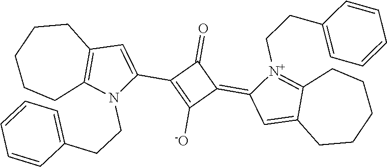
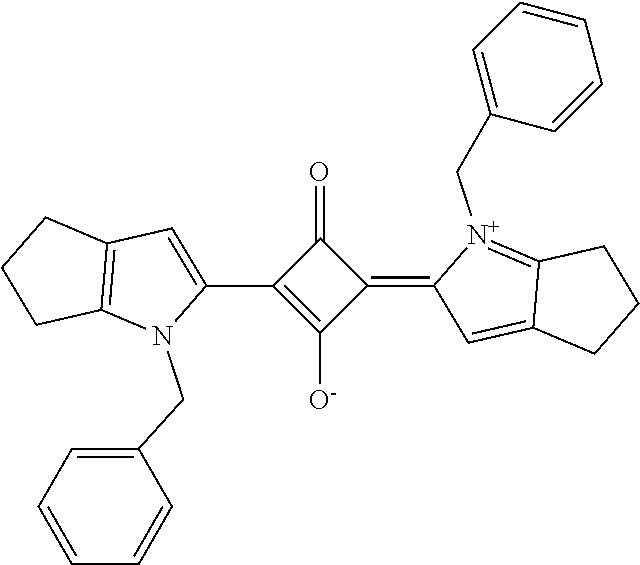
[0075] The colored layer contains, as a coloring material, a compound X represented by the following general formula (I) or general formula (II). The compound X is a compound having an absorption peak in the wavelength band in the range of from 580 nm to 610 nm.
##STR00002##
in the formula (I),
[0076] R.sub.1, R.sub.2, R.sub.3, R.sub.4, R.sub.5, R.sub.6, R.sub.7, and R.sub.8 each independently represent a hydrogen atom, a halogen atom, a substituted or unsubstituted alkyl group having 1 or more and 20 or less carbon atoms, a substituent represented by the formula (a), or a substituent represented by the formula (b),
[0077] R.sub.1 and R.sub.2 form a saturated cyclic skeleton including 5 or 6 carbon atoms, and R.sub.3, R.sub.4, R.sub.5, R.sub.6, R.sub.7, and R.sub.8 each independently represent a hydrogen atom, a halogen atom, which is preferably Cl, a substituted or unsubstituted alkyl group having 1 or more and 20 or less carbon atoms, a substituent represented by the formula (a), or a substituent represented by the formula (b),
[0078] R.sub.2 and R.sub.3 form a saturated cyclic skeleton including 5 to 7 carbon atoms, and R.sub.1, R.sub.4, R.sub.5, R.sub.6, R.sub.7, and R.sub.8 each independently represent a hydrogen atom, a halogen atom, which is preferably Cl, a substituted or unsubstituted alkyl group having 1 or more and 20 or less carbon atoms, a substituent represented by the formula (a), or a substituent represented by the formula (b),
[0079] R.sub.5 and R.sub.6 form a saturated cyclic skeleton including 5 or 6 carbon atoms, and R.sub.1, R.sub.2, R.sub.3, R.sub.4, R.sub.7, and R.sub.8 each independently represent a hydrogen atom, a halogen atom, which is preferably Cl, a substituted or unsubstituted alkyl group having 1 or more and 20 or less carbon atoms, a substituent represented by the formula (a), or a substituent represented by the formula (b),
[0080] R.sub.6 and R.sub.7 form a saturated cyclic skeleton including 5 to 7 carbon atoms, and R.sub.1, R.sub.2, R.sub.3, R.sub.4, R.sub.5, and R.sub.8 each independently represent a hydrogen atom, a halogen atom, which is preferably Cl, a substituted or unsubstituted alkyl group having 1 or more and 20 or less carbon atoms, a substituent represented by the formula (a), or a substituent represented by the formula (b),
[0081] R.sub.1 and R.sub.2 form a saturated cyclic skeleton including 5 or 6 carbon atoms, R.sub.5 and R.sub.6 form a saturated cyclic skeleton including 5 or 6 carbon atoms, and R.sub.3, R.sub.4, R.sub.7, and R.sub.8 each independently represent a hydrogen atom, a halogen atom, which is preferably Cl, a substituted or unsubstituted alkyl group having 1 or more and 20 or less carbon atoms, a substituent represented by the formula (a), or a substituent represented by the formula (b), or
[0082] R.sub.2 and R.sub.3 form a saturated cyclic skeleton including 5 to 7 carbon atoms, R.sub.6 and R.sub.7 form a saturated cyclic skeleton including 5 to 7 carbon atoms, and R.sub.1, R.sub.4, R.sub.5, and R.sub.8 each independently represent a hydrogen atom, a halogen atom, which is preferably Cl, a substituted or unsubstituted alkyl group having 1 or more and 20 or less carbon atoms, a substituent represented by the formula (a), or a substituent represented by the formula (b); and
[0083] in the formula (II), R.sub.4 and R.sub.8 each independently represent a hydrogen atom, or a substituted or unsubstituted alkyl group having 1 or more and 20 or less carbon atoms.
[0084] The saturated cyclic skeleton (number of carbon atoms: 5 or 6) formed so as to include R.sub.1 and R.sub.2, and the saturated cyclic skeleton (number of carbon atoms: 5 or 6) formed so as to include R.sub.5 and R.sub.6 may each have a substituent. The substituent is, for example, an alkyl group having 1 to 4 carbon atoms. In addition, the saturated cyclic skeleton (number of carbon atoms: 5 to 7) formed so as to include R.sub.2 and R.sub.3, and the saturated cyclic skeleton (number of carbon atoms: 5 to 7) formed so as to include R.sub.6 and R.sub.7 may each have a substituent. The substituent is, for example, an alkyl group having 1 to 4 carbon atoms.
[0085] In one embodiment, R.sub.4 and/or R.sub.8 has a benzene ring or a naphthalene ring as a substituent.
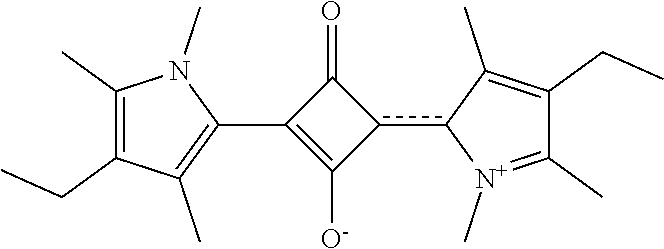
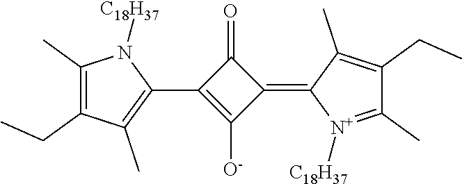
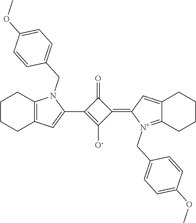
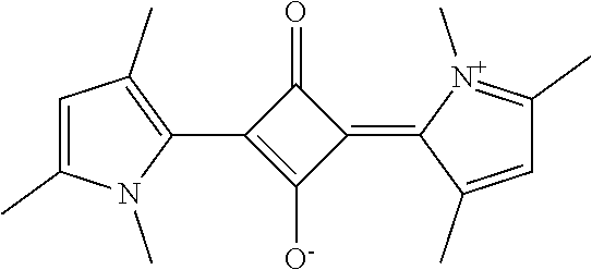
[0086] Specific examples of the compound X represented by the formula (I) or (II) include compounds represented by the following general formulae (I-1) to (I-27) and (II-1). The absorption peak of the compound X is shown in each of the following tables. With regard to each of the formulae (I-1) to (I-23), an absorption peak obtained by measuring the absorbance of a film formed of a resin composition prepared by mixing aliphatic polycarbonate with the compound X is shown, and with regard to each of the formulae (I-24) to (I-27) and (II-1), an absorption peak obtained by measuring the absorbance of a film formed of a resin composition prepared by mixing a polymethyl methacrylate resin with the compound X is shown.
TABLE-US-00001 Absorption peak NO. Compound X (nm) I-1 ##STR00003## 596 nm (APC) I-2 ##STR00004## 595 nm (APC) I-3 ##STR00005## 582 nm (APC) I-4 ##STR00006## 585 nm (APC) I-5 ##STR00007## 585 nm (APC) I-6 ##STR00008## 575 nm (APC) I-7 ##STR00009## 585 nm (APC) I-8 ##STR00010## 587 nm (APC) I-9 ##STR00011## 587 nm (APC) I-10 ##STR00012## 588 nm (APC) I-11 ##STR00013## 588 nm (APC) I-12 ##STR00014## 589 nm (APC) I-13 ##STR00015## 592 nm (APC) I-14 ##STR00016## 591 nm (APC) I-15 ##STR00017## 595 nm (APC) I-16 ##STR00018## 595 nm (APC) I-17 ##STR00019## 596 nm (APC) I-18 ##STR00020## 614 nm (APC) I-19 ##STR00021## 581 nm (APC) I-20 ##STR00022## 591 nm (APC) I-21 ##STR00023## 593 nm (APC) I-22 ##STR00024## 594 nm (APC) I-23 ##STR00025## 594 nm (APC) I-24 ##STR00026## 592 nm I-25 ##STR00027## 593 nm I-26 ##STR00028## 594 nm I-27 ##STR00029## 594 nm II-1 ##STR00030## 597 nm
[0087] The content of the compound X is preferably from 0.01 part by weight to 50 parts by weight, more preferably from 0.05 part by weight to 10 parts by weight, still more preferably from 0.1 part by weight to 5 parts by weight, particularly preferably from 0.1 part by weight to 1 part by weight with respect to 100 parts by weight of a matrix material.
[0088] The colored layer may further contain a compound having an absorption peak in the wavelength band in the range of from 440 nm to 510 nm. For example, an anthraquinone-based, oxime-based, naphthoquinone-based, quinizarin-based, oxonol-based, azo-based, xanthene-based, or phthalocyanine-based compound (dye) is used as such compound.
[0089] The content of the compound having an absorption peak in the wavelength band in the range of from 440 nm to 510 nm is preferably from 0.01 part by weight to 50 parts by weight, more preferably from 0.01 part by weight to 25 parts by weight with respect to 100 parts by weight of the matrix material.
[0090] A-5-2. Matrix
[0091] The matrix may be a pressure-sensitive adhesive, or may be a resin film. The matrix is preferably a pressure-sensitive adhesive.
[0092] When the matrix is a pressure-sensitive adhesive, any appropriate pressure-sensitive adhesive may be used as the pressure-sensitive adhesive. The pressure-sensitive adhesive preferably has transparency and optical isotropy. Specific examples of the pressure-sensitive adhesive include a rubber-based pressure-sensitive adhesive, an acrylic pressure-sensitive adhesive, a silicone-based pressure-sensitive adhesive, an epoxy-based pressure-sensitive adhesive, and a cellulose-based pressure-sensitive adhesive. Of those, a rubber-based pressure-sensitive adhesive or an acrylic pressure-sensitive adhesive is preferred.
[0093] A rubber-based polymer serving as the rubber-based pressure-sensitive adhesive is a polymer showing rubber elasticity in a temperature region around room temperature. Preferred examples of the rubber-based polymer (A) include a styrene-based thermoplastic elastomer (A1), an isobutylene-based polymer (A2), and a combination thereof.
[0094] Examples of the styrene-based thermoplastic elastomer (A1) may include styrene-based block copolymers, such as a styrene-ethylene-butylene-styrene block copolymer (SEBS), a styrene-isoprene-styrene block copolymer (SIS), a styrene-butadiene-styrene block copolymer (SBS), a styrene-ethylene-propylene-styrene block copolymer (SEPS, a hydrogenated product of SIS), a styrene-ethylene-propylene block copolymer (SEP, a hydrogenated product of a styrene-isoprene block copolymer), a styrene-isobutylene-styrene block copolymer (SIBS), and a styrene-butadiene rubber (SBR). Of those, a styrene-ethylene-propylene-styrene block copolymer (SEPS, a hydrogenated product of SIS), a styrene-ethylene-butylene-styrene block copolymer (SEBS), and a styrene-isobutylene-styrene block copolymer (SIBS) are preferred because the copolymers each have polystyrene blocks at both ends of a molecule thereof and have a high cohesive force as a polymer. A commercial product may be used as the styrene-based thermoplastic elastomer (A1). Specific examples of the commercial product include SEPTON and HYBRAR manufactured by Kuraray Co., Ltd., Tuftec manufactured by Asahi Kasei Chemicals Corporation, and SIBSTAR manufactured by Kaneka Corporation.
[0095] The weight-average molecular weight of the styrene-based thermoplastic elastomer (A1) is preferably from about 50,000 to about 500,000, more preferably from about 50,000 to about 300,000, still more preferably from about 50,000 to about 250,000. The weight-average molecular weight of the styrene-based thermoplastic elastomer (A1) preferably falls within such ranges because both of the cohesive force and viscoelasticity of the polymer can be achieved.
[0096] A styrene content in the styrene-based thermoplastic elastomer (A1) is preferably from about 5 wt % to about 70 wt %, more preferably from about 5 wt % to about 40 wt %, still more preferably from about 10 wt % to about 20 wt %. The styrene content in the styrene-based thermoplastic elastomer (A1) preferably falls within such ranges because viscoelasticity based on a soft segment can be secured while a cohesive force based on a styrene moiety is maintained.
[0097] Examples of the isobutylene-based polymer (A2) may include polymers each including isobutylene as a constituent monomer and having a weight-average molecular weight (Mw) of preferably 500,000 or more. The isobutylene-based polymer (A2) may be a homopolymer of isobutylene (polyisobutylene, PIB) or may be a copolymer including isobutylene as amain monomer (i.e., a copolymer obtained by copolymerizing isobutylene at a ratio of more than 50 mol %). Examples of such copolymer may include a copolymer of isobutylene and normal butylene, a copolymer of isobutylene and isoprene (e.g., a butyl rubber, such as a regular butyl rubber, a chlorinated butyl rubber, a brominated butyl rubber, or a partially cross-linked butyl rubber), and vulcanized products and modified products thereof (e.g., a product modified with a functional group, such as a hydroxyl group, a carboxyl group, an amino group, or an epoxy group). Of those, polyisobutylene (PIB) is preferred because the polyisobutylene is free of a double bond in its main chain, and is excellent in weatherability. A commercial product may be used as the isobutylene-based polymer (A2). The commercial product is specifically, for example, OPPANOL manufactured by BASF.
[0098] The weight-average molecular weight (Mw) of the isobutylene-based polymer (A2) is preferably 500,000 or more, more preferably 600,000 or more, still more preferably 700,000 or more. In addition, the upper limit of the weight-average molecular weight (Mw) is preferably 5,000,000 or less, more preferably 3,000,000 or less, still more preferably 2,000,000 or less. When the weight-average molecular weight of the isobutylene-based polymer (A2) is set to 500,000 or more, a pressure-sensitive adhesive that is more excellent in durability at the time of its high-temperature storage can be obtained.
[0099] The content of the rubber-based polymer (A) in the pressure-sensitive adhesive is preferably 30 wt % or more, more preferably 40 wt % or more, still more preferably 50 wt % or more, particularly preferably 60 wt % or more in the total solid content of the pressure-sensitive adhesive. The upper limit of the content of the rubber-based polymer is preferably 95 wt % or less, more preferably 90 wt % or less.
[0100] In the rubber-based pressure-sensitive adhesive, the rubber-based polymer (A) and any other rubber-based polymer may be used in combination. Specific examples of the other rubber-based polymer include: a butyl rubber (IIR), a butadiene rubber (BR), an acrylonitrile-butadiene rubber (NBR), EPR (binary ethylene-propylene rubber), EPT (ternary ethylene-propylene rubber), an acrylic rubber, a urethane rubber, and a polyurethane-based thermoplastic elastomer; a polyester-based thermoplastic elastomer; and a blend-based thermoplastic elastomer, such as a polymer blend of polypropylene and EPT (ternary ethylene-propylene rubber). The compounding amount of the other rubber-based polymer is preferably about 10 parts by weight or less with respect to 100 parts by weight of the rubber-based polymer (A).
[0101] The acrylic polymer of the acrylic pressure-sensitive adhesive typically contains an alkyl (meth)acrylate as a main component, and may contain an aromatic ring-containing (meth)acrylate, an amide group-containing monomer, a carboxyl group-containing monomer, and/or a hydroxyl group-containing monomer as a copolymerization component in accordance with a purpose. The term "(meth)acrylate" as used herein means an acrylate and/or a methacrylate. The alkyl (meth)acrylate may be, for example, an alkyl (meth)acrylate having a linear or branched alkyl group having 1 to 18 carbon atoms. The aromatic ring-containing (meth)acrylate is a compound containing an aromatic ring structure in its structure and containing a (meth)acryloyl group. The aromatic ring is, for example, a benzene ring, a naphthalene ring, or a biphenyl ring. The aromatic ring-containing (meth)acrylate satisfies durability and can alleviate display unevenness due to a white void of the peripheral portion of an image display apparatus. The amide group-containing monomer is a compound containing an amide group in its structure and containing a polymerizable unsaturated double bond, such as a (meth)acryloyl group or a vinyl group. The carboxyl group-containing monomer is a compound containing a carboxyl group in its structure and containing a polymerizable unsaturated double bond, such as a (meth)acryloyl group or a vinyl group. The hydroxyl group-containing monomer is a compound containing a hydroxyl group in its structure and containing a polymerizable unsaturated double bond, such as a (meth)acryloyl group or a vinyl group. Details about the acrylic pressure-sensitive adhesive are described in, for example, JP 2015-199942 A, the description of which is incorporated herein by reference.
[0102] When the matrix is a resin film, any appropriate resin may be used as a resin forming the resin film. Specifically, the resin may be a thermoplastic resin, may be a thermosetting resin, or may be an active energy ray-curable resin. Examples of the active energy ray-curable resin include an electron beam-curable resin, a UV-curable resin, and a visible light-curable resin. Specific examples of the resin include an epoxy, a (meth)acrylate (e.g., methyl methacrylate or butyl acrylate), norbornene, polyethylene, poly(vinyl butyral), poly(vinyl acetate), polyurea, polyurethane, aminosilicone (AMS), polyphenylmethylsiloxane, a polyphenylalkylsiloxane, polydiphenylsiloxane, a polydialkylsiloxane, silsesquioxane, silicone fluoride, vinyl- and hydride-substituted silicones, a styrene-based polymer (e.g., polystyrene, aminopolystyrene (APS), poly(acrylonitrile ethylene styrene) (AES)), a polymer having cross-linked with a di functional monomer (e.g., divinylbenzene), a polyester-based polymer (e.g., polyethylene terephthalate), a cellulose-based polymer (e.g., triacetyl cellulose), a vinyl chloride-based polymer, an amide-based polymer, an imide-based polymer, a vinyl alcohol-based polymer, an epoxy-based polymer, a silicone-based polymer, and an acrylic urethane-based polymer. Those resins may be used alone or in combination thereof (e.g., a blend or a copolymer). Those resins may each be subjected to a treatment, such as stretching, heating, or pressurization, after forming a film. Of those, a thermosetting resin or a UV-curable resin is preferred, and a thermosetting resin is more preferred.
[0103] B. Image Display Apparatus
[0104] An image display apparatus of the present invention includes an image display panel and the circularly polarizing plate. Examples of the image display panel include a liquid crystal display panel and an organic EL panel. The circularly polarizing plate is arranged on the viewer side of the image display panel, and is arranged so that the colored layer may be on an image display panel side, and the polarizer may be on the viewer side.
[0105] An image display panel having a high reflectance (e.g., an image display panel that includes, for example, a member formed of a metal or a member containing a metal, and that has a high reflectance) is suitably used as the image display panel. The circularlypolarizingplate of the present invention has an excellent antireflection characteristic and an excellent hue-adjusting function. Accordingly, even in an image display apparatus including the image display panel having a high reflectance, the influence of ambient light reflection can be effectively reduced. The visible light reflectance of the image display panel is, for example, 20% or more, preferably from 40% to 99%.
EXAMPLES
[0106] Now, the present invention is specifically described byway of Examples. However, the present invention is by no means limited by these Examples. Methods of measuring the respective characteristics are as described below.
[0107] [Evaluation]
(1) Measurement of Absorption Spectrum
[0108] A colored layer was dissolved in ethyl acetate to prepare an evaluation sample.
[0109] The absorption spectrum of the evaluation sample was measured with a spectrophotometer (manufacturedby Hitachi High-Technologies Corporation, product name: "U-4100").
(2) Measurement of Color Gamut
[0110] A circularly polarizing plate was arranged on the viewer side of iPad manufactured by Apple Inc. so that its colored layer was on an iPad side. Thus, an evaluation sample was obtained.
[0111] In a dark room, chromaticities at the time of the red display of the evaluation sample, at the time of the blue display thereof, and at the time of the green display thereof were measured with a luminance colorimeter (manufactured by Topcon Technohouse Corporation, product name: "SR-UL1"). A DCI ratio (area B/area A) was calculated from the area A of a triangle formed by connecting the chromaticity coordinates of the respective colors, and the area B of a region where the triangle formed by connecting the chromaticity coordinates of the respective colors and the color gamut standard of DCI overlapped each other.
(3) Measurement of Reflectance of Circularly Polarizing Plate
[0112] A circularly polarizing plate was bonded to a reflective plate (manufactured by Toray Advanced Film Co., Ltd., product name: "CERAPEEL DMS-X42", total light reflectance: 86%) so that its colored layer was on a reflective plate side. Thus, an evaluation sample was produced. The total light reflectance of the evaluation sample was measured with CM2600-d (manufactured by Konica Minolta, Inc.).
(4) .DELTA.ab
[0113] The reflection hue (L*a*b* colorimetric system) of the evaluation sample produced in the (3) was measured with CM2600-d (manufactured by Konica Minolta, Inc.), and the Lab thereof was determined from the equation ".DELTA.ab=(a.sup.2+b.sup.2).sup.1/2".
Example 1
(i) Production of Retardation Layer (.lamda./4 Plate)
[0114] Polymerization was performed by using a batch polymerization apparatus formed of two vertical reactors each including a stirring blade and a reflux condenser controlled to 100.degree. C. 9,9-[4-(2-Hydroxyethoxy)phenyl]fluorene (BHEPF), isosorbide (ISB), diethylene glycol (DEG), diphenyl carbonate (DPC), and magnesium acetate tetrahydrate were loaded into a first reactor so that a molar ratio "BHEPF/ISB/DEG/DPC/magnesium acetate" became 0.348/0.490/0.162/1.005/1.00.times.10.sup.-5. After air in the reactor had been sufficiently purged with nitrogen (oxygen concentration: from 0.0005 vol % to 0.001 vol %), a temperature in the reactor was warmed with a heating medium, and stirring was started at the time point when the internal temperature became 100.degree. C. 40 Minutes after the start of the temperature increase, the internal temperature was caused to reach 220.degree. C., and such control that the temperature was held was performed. Simultaneously with the control, the reduction of a pressure in the reactor was started, and the pressure was set to 13.3 kPa in 90 minutes after the temperature had reached 220.degree. C. Phenol vapor produced as a by-product of the polymerization reaction was introduced into the reflux condenser at 100.degree. C. A monomer component present in a trace amount in the phenol vapor was returned to the reactor, and the phenol vapor that did not condense was introduced into a condenser at 45.degree. C. and collected.
[0115] Nitrogen was introduced into the first reactor to return the pressure to atmospheric pressure once. After that, the oligomerized reaction liquid in the first reactor was transferred to a second reactor. Next, the increase of a temperature in the second reactor and the reduction of a pressure therein were started, and the internal temperature and the pressure were set to 240.degree. C. and 0.2 kPa, respectively in 50 minutes. After that, polymerization was advanced until predetermined stirring power was obtained. At the time point when the predetermined power was achieved, nitrogen was introduced into the reactor to return the pressure to atmospheric pressure. The reaction liquid was extracted in the form of a strand, and was pelletized with a rotary cutter to provide a polycarbonate resin having a copolymerization composition "BHEPF/ISB/DEG" of 34.8/49.0/16.2 [mol %]. The polycarbonate resin had a reduced viscosity of 0.430 dL/g and a glass transition temperature of 128.degree. C.
[0116] The resultant polycarbonate resin (10 kg) was dissolved in methylene chloride (73 kg) to prepare an application liquid. Next, the application liquid was directly applied onto a shrinkable film (longitudinally uniaxially stretched polypropylene film, manufactured by Tokyo Printing Ink Mfg Co., Ltd., product name: "NOBLEN"). The applied film was dried at a drying temperature of 30.degree. C. for 5 minutes and at a drying temperature of 80.degree. C. for 5 minutes to form a laminate having the configuration "shrinkable film/birefringent layer". The resultant laminate was stretched with a simultaneous biaxial stretching machine at a stretching temperature of 155.degree. C. in its MD direction at a shrinkage ratio of 0.80 times and in its TD direction at a stretching ratio of 1.3 times to form a retardation film A on the shrinkable film. Next, the retardation film was peeled from the shrinkable film. The retardation film A had a thickness of 60.0 .mu.m, an Re(550) of 140 nm, an Nz coefficient of 0.5, and a ratio Re(450)/Re(550) of 0.89. The retardation film A was adopted as a retardation layer (.lamda./4 plate).
[0117] (ii) Production of Polarizer
[0118] An elongate roll of a polyvinyl alcohol (PVA)-based resin film having a thickness of 30 .mu.m (manufactured by Kuraray Co., Ltd., product name: "PE3000") was uniaxially stretched with a roll stretching machine in its lengthwise direction at a stretching ratio of 5.9 times in the lengthwise direction. Simultaneously with the stretching, the film was subjected to swelling, dyeing, cross-linking, and washing treatments, and was finally subjected to a drying treatment to produce a polarizer having a thickness of 12 .mu.m.
[0119] Specifically, in the swelling treatment, the film was stretched at a stretching ratio of 2.2 times while being treated with pure water at 20.degree. C. Next, in the dyeing treatment, the film was stretched at a stretching ratio of 1.4 times while being treated in an aqueous solution at 30.degree. C. containing iodine and potassium iodide at a weight ratio of 1:7 in which an iodine concentration was adjusted so that the single layer transmittance of the polarizer to be obtained became 45.0%. Further, in the cross-linking treatment, a two-stage cross-linking treatment was adopted, and in a first-stage cross-linking treatment, the film was stretched at a stretching ratio of 1.2 times while being treated in an aqueous solution at 40.degree. C. having dissolved therein boric acid and potassium iodide. The boric acid content of the aqueous solution in the first-stage cross-linking treatment was set to 5.0 wt %, and the potassium iodide content thereof was set to 3.0 wt %. In a second-stage cross-linking treatment, the film was stretched at a stretching ratio of 1.6 times while being treated in an aqueous solution at 65.degree. C. having dissolved therein boric acid and potassium iodide. The boric acid content of the aqueous solution in the second-stage cross-linking treatment was set to 4.3 wt %, and the potassium iodide content thereof was set to 5.0 wt %. In addition, in the washing treatment, the film was treated with a potassium iodide aqueous solution at 20.degree. C. The potassium iodide content of the aqueous solution in the washing treatment was set to 2.6 wt %. Finally, in the drying treatment, the film was dried at 70.degree. C. for 5 minutes to provide the polarizer.
[0120] (iii) Production of Polarizing Plate A
[0121] AHC-TAC film (thickness: 32 .mu.m, corresponding to a protective film) including a hard coat (HC) layer formed on one surface of a TAC film by a hard coat treatment was bonded to one side of the polarizer via a polyvinyl alcohol-based adhesive through a roll-to-roll process. Thus, an elongate polarizing plate A having the configuration "protective film/polarizer" was obtained.
[0122] (iv) Production of Polarizing Plate A with Retardation Layer
[0123] The polarizing plate and the retardation layer obtained in the foregoing were each cut into a predetermined size, and the polarizer surface of the polarizing plate and the retardation layer were bonded to each other via an acrylic pressure-sensitive adhesive. Thus, a polarizing plate A with a retardation layer having the configuration "protective film/polarizer/retardation layer (.lamda./4 plate)" was obtained. The retardation layer was cut so that an angle formed by the absorption axis of the polarizer and the slow axis of the retardation layer became 45.degree. at the time of the bonding of the polarizing plate and the retardation layer.
[0124] (v) Formation of Colored Layer
[0125] A coloring matter-containing pressure-sensitive adhesive containing 0.3 part by weight of a radical generator (benzoyl peroxide, manufactured by Nippon Oil & Fats Co., Ltd., product name: "NYPER BMT"), 1 part by weight of an isocyanate-based cross-linking agent (manufactured by Tosoh Corporation, product name: "CORONATE L"), 0.25 part by weight of a squaraine compound represented by the following general formula (I-20), and 0.2 part by weight of a phenol-based antioxidant (manufactured by BASF Japan Ltd., product name: "IRGANOX 1010") with respect to 100 parts by weight of an acrylic polymer obtained by copolymerizing n-butyl acrylate and a hydroxy group-containing monomer was produced. The pressure-sensitive adhesive was applied onto a PET substrate (manufacturedbyMitsubishi Plastics, Inc., product name: "MRF38CK"), which had been subjected to a treatment for facilitating the peeling of the pressure-sensitive adhesive, with an applicator so as to have a thickness of 20 .mu.m, and the adhesive was dried at 155.degree. C. for 2 minutes. After that, the pressure-sensitive adhesive sample was removed, and the pressure-sensitive adhesive surface was bonded to the retardation layer side of the polarizing plate with a retardation layer. Thus, a colored layer (absorption maximum wavelength: 594 nm) was formed.
[0126] The squaraine compound represented by the general formula (I-20) was synthesized by the following method.
<Synthesis of Squaraine Compound>
[0127] 1-Phenyl-1,4,5,6-tetrahydrocyclopenta[b]pyrrole was synthesized by a method described in "M. Beller et. al., J. Am. Chem. Soc., 2013, 135(30), 11384-11388".
[0128] 300 Milligrams of 1-phenyl-1,4,5,6-tetrahydrocyclopenta[b]pyrrole and 80 mg of squaric acid were mixed in 5 mL of ethanol, and the mixture was stirred at 80.degree. C. for 2 hours. After that, the mixture was cooled to room temperature, and the product was filtered out. The product that had been filtered out was washed with ethanol, and was dried under reduced pressure at 70.degree. C. to provide 197 mg of a squaraine compound. Further, the compound was purified by silica gel chromatography to provide 120 mg of a squaraine compound.
##STR00031##
[0129] A circularly polarizing plate including the protective film, the polarizer, the retardation layer (.lamda./4 plate), and the colored layer was obtained as described above. The resultant circularly polarizing plate was subjected to the evaluations (2) to (4). The results are shown in Table 1.
Comparative Example 1
[0130] (i) Production of Polarizing Plate A with Retardation Layer
[0131] The polarizing plate A with a retardation layer was obtained in the same manner as in Example 1.
[0132] (ii) Formation of Colored Layer
[0133] A circularly polarizing plate including the protective film, the polarizer, the retardation layer (.lamda./4 plate), and a colored layer (absorption maximum wavelength: 595 nm) was obtained in the same manner as in Example 1 except that 0.25 part by weight of a porphyrin-based coloring matter (manufactured by Yamamoto Chemicals, Inc., product name: "PD-320") was used instead of 0.25 part by weight of the squaraine compound represented by the general formula (I-20). The resultant circularly polarizing plate was subjected to the evaluations (2) to (4). The results are shown in Table 1.
Comparative Example 2
[0134] A circularly polarizing plate was obtained in the same manner as in Example 1 except that the coloring matter (squaraine compound) was not incorporated into the pressure-sensitive adhesive forming the colored layer (i.e., a pressure-sensitive adhesive layer was formed instead of the colored layer). The resultant circularly polarizing plate was subjected to the evaluations (2) to (4). The results are shown in Table 1.
TABLE-US-00002 TABLE 1 Color gamut Reflectance (DCI ratio) Coloring matter (%) .DELTA.ab (%) Example 1 Squaraine compound 2.39 22.3 57 (formula (II)) Comparative Porphyrin-based 2.49 26.7 55 Example 1 coloring matter Comparative -- 2.66 25.1 51 Example 2
[0135] As is apparent from Table 1, according to the present invention, a circularly polarizing plate that is excellent in antireflection characteristic, that can output light having a small Lab and a neutral hue, and that can widen the color gamut of an image display apparatus can be obtained.
INDUSTRIAL APPLICABILITY
[0136] The circularly polarizing plate of the present invention is suitably used in an image display apparatus, such as a liquid crystal display apparatus.
REFERENCE SIGNS LIST
[0137] 10 polarizer [0138] 20a retardation layer [0139] 30 colored layer [0140] 100 circularly polarizing plate
* * * * *


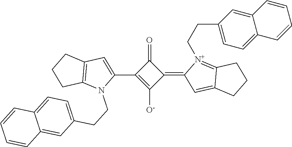

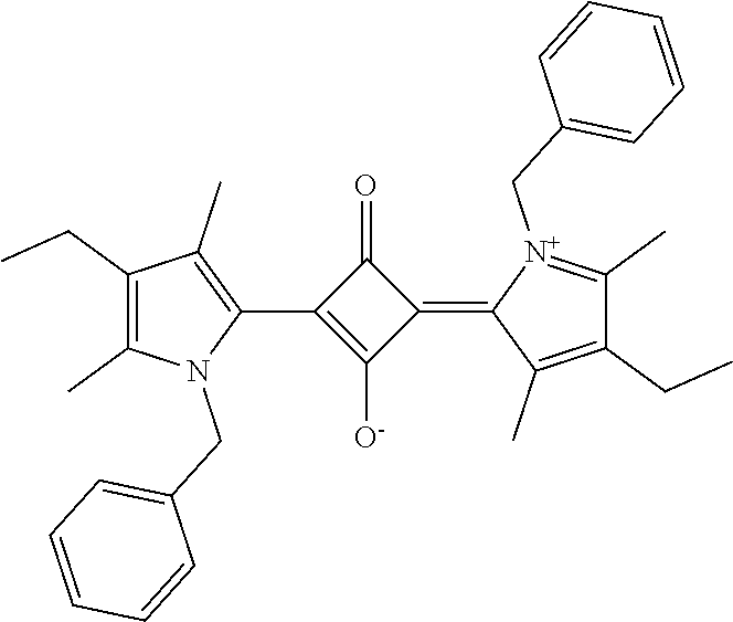


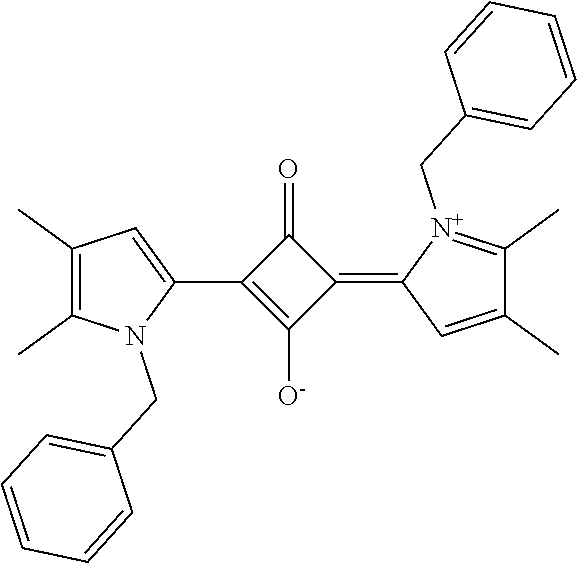

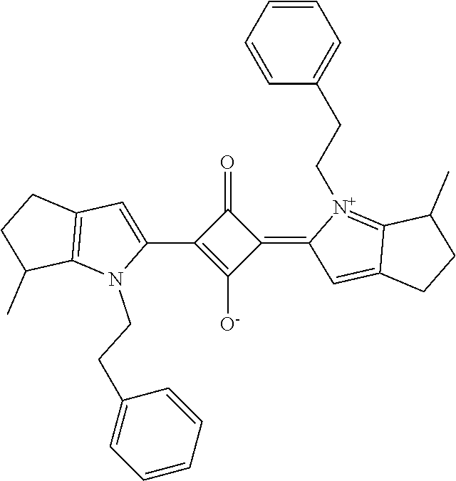


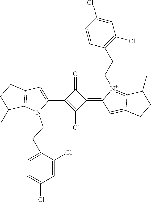

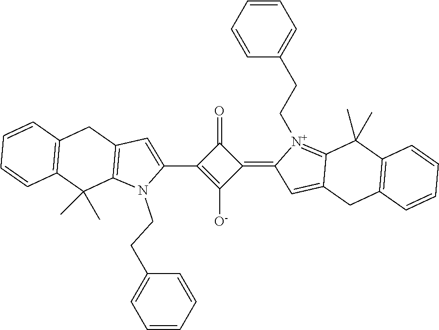


D00000

D00001

XML
uspto.report is an independent third-party trademark research tool that is not affiliated, endorsed, or sponsored by the United States Patent and Trademark Office (USPTO) or any other governmental organization. The information provided by uspto.report is based on publicly available data at the time of writing and is intended for informational purposes only.
While we strive to provide accurate and up-to-date information, we do not guarantee the accuracy, completeness, reliability, or suitability of the information displayed on this site. The use of this site is at your own risk. Any reliance you place on such information is therefore strictly at your own risk.
All official trademark data, including owner information, should be verified by visiting the official USPTO website at www.uspto.gov. This site is not intended to replace professional legal advice and should not be used as a substitute for consulting with a legal professional who is knowledgeable about trademark law.