Microscope Objective And Microscope Having Such An Objective
OHRT; Thomas ; et al.
U.S. patent application number 16/640706 was filed with the patent office on 2020-11-12 for microscope objective and microscope having such an objective. The applicant listed for this patent is Carl Zeiss Microscopy GmbH. Invention is credited to Michael GOEGLER, Thorsten KUES, Thomas OHRT.
| Application Number | 20200355901 16/640706 |
| Document ID | / |
| Family ID | 1000005005499 |
| Filed Date | 2020-11-12 |

| United States Patent Application | 20200355901 |
| Kind Code | A1 |
| OHRT; Thomas ; et al. | November 12, 2020 |
MICROSCOPE OBJECTIVE AND MICROSCOPE HAVING SUCH AN OBJECTIVE
Abstract
A microscope objective for imaging a specimen using a microscope, the microscope objective being designed as an air objective for microscopy without an immersion medium or as an oil immersion objective for microscopy with an oil-based immersion medium or as a water immersion objective for microscopy with a water-based immersion medium. The front lens of the microscope objective is provided with a coating which repels an immersion medium and is lipophobic and hydrophobic if the objective is an air objective, only lipophobic if the objective is a water immersion objective, and only hydrophobic if the objective is an oil immersion objective.
| Inventors: | OHRT; Thomas; (Golmsdorf, DE) ; GOEGLER; Michael; (Wolfratshausen, DE) ; KUES; Thorsten; (Bovenden-Eddigehausen, DE) | ||||||||||
| Applicant: |
|
||||||||||
|---|---|---|---|---|---|---|---|---|---|---|---|
| Family ID: | 1000005005499 | ||||||||||
| Appl. No.: | 16/640706 | ||||||||||
| Filed: | August 6, 2018 | ||||||||||
| PCT Filed: | August 6, 2018 | ||||||||||
| PCT NO: | PCT/EP2018/071272 | ||||||||||
| 371 Date: | February 20, 2020 |
| Current U.S. Class: | 1/1 |
| Current CPC Class: | G02B 1/18 20150115; G02B 21/02 20130101; G02B 21/33 20130101; G02B 21/0088 20130101 |
| International Class: | G02B 21/33 20060101 G02B021/33; G02B 1/18 20060101 G02B001/18; G02B 21/00 20060101 G02B021/00; G02B 21/02 20060101 G02B021/02 |
Foreign Application Data
| Date | Code | Application Number |
|---|---|---|
| Aug 21, 2017 | DE | 102017119095.3 |
Claims
1. A microscope objective for imaging a sample using a microscope, wherein the microscope objective is embodied as an air objective for microscopy without an immersion medium or as an oil immersion objective for microscopy with an oil-based immersion medium or as a water immersion objective for microscopy with a water-based immersion medium, microscope objective including a front lens configured to repel an immersion medium, the front lens coated with a coating that is lipophobic and hydrophobic in the case of the embodiment as an air objective, purely lipophobic in the case of the embodiment as a water immersion objective and purely hydrophobic in the case of the embodiment as an oil immersion objective.
2. The microscope objective as claimed in claim 1, further comprising a lens surround and a lens casing, each of the lens surround and the lens casing including an immersion medium-repellent layer, said layer configured to revel the immersion medium for which the microscope objective is designed.
3. The microscope objective as claimed in claim 2, wherein the layer surrounds the front lens and, on the lens surround and the lens casing, defines an area free of the immersion-medium repellent that extends away from the front lens and acts as a drainage channel for repelled immersion medium.
4. The microscope objective as claimed in claim 2, wherein the layer is lipophobic and hydrophobic.
5. A microscope objective for imaging a sample using a microscope, wherein the microscope objective is embodied as a multi-immersion objective for selectively carrying out microscopy without an immersion medium or with an oil-based immersion medium or with a water-based immersion medium, wherein the microscope objective comprises a first cap provided for microscopy without an immersion medium, a second cap provided for microscopy with a water-based immersion medium and a third cap provided for microscopy with an oil-based immersion medium, which caps are each placeable over the front lens and are immersion medium-repellent, wherein the first cap is lipophobic and hydrophobic, the second cap is only lipophobic and the third cap is only hydrophobic.
6. The microscope objective as claimed in claim 5, wherein the caps are only placeable on the microscope objective at a certain angular position and are immersion medium-repellent on an edge of the caps that surrounds the front lens, and the microscope objection includes in that a lens casing that is lipophobic and hydrophobic.
7. The microscope objective as claimed in claim 6, wherein a field that extends away from the front lens is not immersion-repellent and acts as a drainage channel for repelled immersion medium.
8. The microscope objective as claimed in claim 1, further comprising a receptacle for drained immersion medium.
9. The microscope objective as claimed in claim 8, wherein the drainage channel ends at the receptacle, and the microscope objective further comprises a lens surround and a lens casing, each of the lens surround and the lens casing including an immersion medium-repellent layer, said layer configured to repel the immersion medium for which the microscope objective is designed, and the layer surrounds the front lens, and on the lens surround and the lens casing defines an area free of the immersion-medium repellent, the area extending away from the front lens and acting as the drainage channel for repelled immersion medium.
10. The microscope objective as claimed in claim 1, wherein a joint of the microscope objective and/or lens mount of the microscope objective are/is lipophobic and hydrophobic.
11. A microscope comprising a microscope objective as claimed in claim 1.
12. The microscope as claimed in claim 11, wherein a connection point between the microscope objective and an objective holder is lipophobic and hydrophobic.
13. The microscope objective as claimed in claim 5, comprising a receptacle for drained immersion medium.
14. The microscope objective as claimed in claim 13, wherein the drainage channel ends at the receptacle, and the microscope objective further comprises a lens surround and a lens casing, each of the lens surround and the lens casing including an immersion medium-repellent layer, said layer configured to repel the immersion medium for which the microscope objective is designed, and the layer surrounds the front lens, and on the lens surround and the lens casing defines an area free of the immersion-medium repellent, the area extending away from the front lens and acting as the drainage channel for repelled immersion medium.
Description
PRIORITY CLAIM
[0001] The present application is a National Phase entry of PCT Application No. PCT/EP2018/071274, filed Aug. 8, 2018, which claims priority from German Patent Application 10 2017 119 093.7, filed Aug. 21, 2017, the disclosures of which are hereby incorporated by reference herein in their entirety.
FIELD OF THE INVENTION
[0002] The invention relates to a microscope objective for imaging a sample using a microscope, wherein the microscope objective comprises a front lens enclosed by a surround and is embodied for microscopy with an immersion liquid. Further, the invention relates to a sample carrier or cover slip for examining a sample, to be disposed on the sample carrier or under the cover slip, by immersion microscopy. The invention likewise relates to a method for examining a sample by microscopy using an immersion microscope in a microscopy process, wherein use is made of a microscope objective that comprises a front lens enclosed by a surround. Finally, the invention also relates to an immersion microscope comprising a microscope objective of the aforementioned type.
BACKGROUND OF THE INVENTION
[0003] The prior art has disclosed various approaches for ensuring that a front lens of a microscope objective is wetted as completely as possible with an immersion medium. EP 1717628 A1 and EP 2256535 A1 disclose a mechanism for inverted microscope objectives, i.e., microscope objectives that examine a sample by microscopy from below. A mechanism is provided on the front edge of the objective casing, said mechanism preventing a drop of immersion liquid placed on the front lens from running off over the front edge of the objective casing. Moreover, provision is made of outflow tubes that drain the immersion liquid downward in targeted fashion. An inner zone of the edge is configured to repel the immersion liquid for which the microscope is designed. A surrounding outer zone is configured in exactly the opposite way, and so it drains immersion liquid reaching it to the outside. With reference to further publications, JP 4603295 discusses various concepts that avoid contamination of the objective interior with immersion liquid. Two of the solutions described therein correspond to those of the specified EP documents. A third solution, which is described in the Japanese publication, provides for a groove on the objective that prevents excess immersion liquid from running into the objective. Further, for an oil immersion-based microscope, JP 4603295 proposes a lipophilic coating on the lens surface, which is surrounded by a lipophobic coating on the edge of the lens surface. Thus, the prior art is concerned in various approaches with avoiding contamination of an objective with immersion liquid or draining excess immersion liquid in a targeted manner.
SUMMARY OF THE INVENTION
[0004] Difficulties arise when using immersion media, particularly in the case of scanning microscopy. The travel speed with which the objective can be displaced over the sample is limited by the fact that shear forces occur at too high movement speeds, said shear forces possibly leading to the immersion film tearing off or to an inadmissible deformation of an elastomeric immersion medium. In the case of an elastomeric immersion medium, an excessive shear force can sometimes displace the cover slip and thus lead to the sample being destroyed. A sample holder that is not completely fixed can also be displaced in this way, rendering it impossible to approach defined coordinates in the sample again. These problems can only be counteracted by using an excessive amount of immersion medium at the beginning of the microscopy process in order to compensate for the fact that the immersion medium is lost or deformed due to the travel speed and the resulting shear forces, leading to parts of the beam path being without immersion medium. As a result, however, the sample becomes contaminated by the immersion medium and the immersion medium consumption is sometimes quite high, which is costly.
[0005] Particularly in the case of microscope objectives that can be used with different immersion liquids, it is tedious for a user to remove the immersion liquids. Contamination of the objective with immersion liquid is a problem. A contaminated immersion objective, to which remains of an immersion liquid that is not suitable for the current microscopy process adheres, leads to poor imaging quality.
[0006] The invention is therefore based on the object of ensuring a consistently high imaging quality in microscopy.
[0007] Embodiments of the invention are defined in the independent and dependent claims.
[0008] The microscope objective for imaging a sample using an immersion microscope comprises a front lens. This is enclosed by a surround. It is embodied for microscopy with an immersion liquid. The front side, e.g., the front lens and/or the surround thereof, can be switched between a state that repels the immersion liquid and a state that does not repel, or even attracts, the immersion liquid. As an alternative or in addition thereto, the sample carrier or the cover slip has such a configuration. This can be achieved in each case by way of a surface treatment, which imparts the desired, switchable repulsive properties. The treatment can be a coating. Equally, a structure could be introduced into the surface, said structure producing the properties, or the surface could be treated in some other way, for example chemically, in order to obtain the properties. Insofar as coatings are mentioned below, this is purely by way of example.
[0009] Coatings are known, for example, from J. Lahann, et al., "A Reversibly Switching Surface", Science, Vol. 299, pages 371 to 374, or N. Nakayama, et al., "Light-Sensitive Fluorpolymer Coated Surface for Control of Cell Adhesion Behaviour", Front. Bioeng. Biotechnol. Conference Abstract: 10th World Biomaterials Congress. doi: 10.3389/conf.FBIOE.2016.01.01728, or R. Rosario, et al., "Lotus Effect Amplifies Light-Induced Contact Angle Switching", J. Phys. Chem. B. Letters 2004, 108 (34), pages 12640-12642.
[0010] The microscope objective can be switched, either electrically or by radiating in illumination of a certain type, between a state that repels a liquid and a state that does not repel, or sometimes even attracts, the liquid. This switchability allows easy cleaning of the microscope objective by virtue of switching the treatment into the state that repels the immersion liquid. The immersion liquid then runs off on the microscope objective.
[0011] The provision of a drainage channel for repelled immersion liquid on the objective by virtue of providing an immersion-repellent border, e.g., a layer, on the surround and on an objective casing, said border enclosing the front lens, is preferred. Said border leaves a field, which extends away from the front side, clear on the objective surround and objective casing. It defines a drainage channel. The immersion medium-repellent treatment used in the process can be the same as on the front lens of the microscope objective. However, since immersion medium should preferably not adhere to the objective surround and objective casing at any time, it is preferable to make them constantly lipophobic and hydrophobic. The provision of a receptacle for the drained immersion medium at the end of the drainage channel is expedient.
[0012] Within the scope of the invention, the switchable repulsion property can also be provided on a sample carrier or a cover slip for microscopy. The terms "sample carrier" and "cover slip" should be interpreted broadly here and comprise membranes or other sample delimiting elements, in particular. Such elements are included insofar as the sample carrier or cover slip is mentioned below. This reduces the contamination on the side of the preparation and ensures the complete wetting of the surface, so that there are no image artifacts due to scratches and contamination.
[0013] In the case of a microscope comprising a microscope objective with the aforementioned switchability, a control device is preferably embodied in such a way that it cleans the immersion liquid off the microscope objective following the completion of a microscopy process by virtue of switching the objective and/or sample carrier/cover slip into the state that repels the immersion liquid.
[0014] This switchover by the controller can advantageously be used if the microscope comprises both the specified microscope objective and the specified sample carrier or cover slip. Here, the sample can be scanned to find a region to be examined by microscopy, wherein, in this state, the control device switches the sample carrier or the cover slip into the state that repels the coating. In the scanning immersion microscopy subsequently carried out, the surface of the sample carrier or of the cover slip, over which the immersion objective wetted with the immersion medium is displaced in relative fashion, is in a state that repels the immersion medium. In this way, much lower shear forces act in the immersion medium. The surface is not smeared with immersion liquid. A drop, once applied, remains on the objective because, due to the repulsive coating, it does not adhere to, or smear on, the surface of the sample carrier or cover slip. Once the region to be imaged has been found within the scope of the scanning process, the control device switches the coating on the sample carrier/cover slip into the state that does not repel the immersion liquid. This ensures an optimal wetting of the sample carrier or of the cover slip and of the microscope objective with the immersion liquid when the region to be imaged is examined by microscopy.
[0015] The repulsive treatment of the sample carrier or cover slip allows the immersion objective to be removed from the sample in such a way that as far as possible no immersion liquid remains on the sample carrier/cover slip. There are various options here. Firstly, the objective can simply be removed from the surface of the sample carrier/cover slip. In so doing, the distance between the objective and the treated surface is increased until the immersion liquid remains as completely as possible on the objective due to the repulsive properties of the surface of the sample carrier/cover slip. As an alternative or in addition thereto, the objective can be displaced laterally with respect to the surface until it has been moved over the edge of the sample carrier/cover slip. In this way, the immersion liquid is likewise manipulated such that it remains on the objective and not on the sample carrier/cover slip. This procedure is advantageous in that a change between an objective with immersion and an objective without immersion, e.g., an objective embodied as an overview objective, is easily possible, without the image deteriorating. As no immersion liquid remains on the surface following the removal of the immersion objective, no disturbances arise for the immersion-free objective, e.g., the overview objective, either.
[0016] The proposed measures are possible in the case of an inverted microscope, and equally in the case of upright microscopy or for light sheet microscopy, too.
[0017] It is understood that the features specified above and the features yet to be explained below can be used not only in the specified combinations, but also in other combinations or on their own, without departing from the scope of the present invention.
BRIEF DESCRIPTION OF THE DRAWINGS
[0018] The invention is explained in even more detail below on the basis of exemplary embodiments, with reference being made to the appended drawings, which likewise disclose features essential to the invention. These exemplary embodiments are only illustrative and should not be construed as restrictive. By way of example, a description of an exemplary embodiment with a multiplicity of elements or components should not be construed as meaning that all of these elements or components are necessary for implementation. Rather, other exemplary embodiments could also contain alternative elements and components, fewer elements or components or additional elements or components. Elements or components of different exemplary embodiments can be combined with one another, unless stated otherwise. Modifications and variations, which are described for one of the exemplary embodiments, can also be applicable to other exemplary embodiments. To avoid repetitions, the same or corresponding elements in different figures are denoted by the same reference sign and are not explained multiple times. In the figures:
[0019] FIG. 1 shows a schematic illustration of an inverted microscope,
[0020] FIG. 2 shows an enlarged detail of the illustration in FIG. 1,
[0021] FIG. 3 shows the top side of the objective of the microscope in FIG. 1,
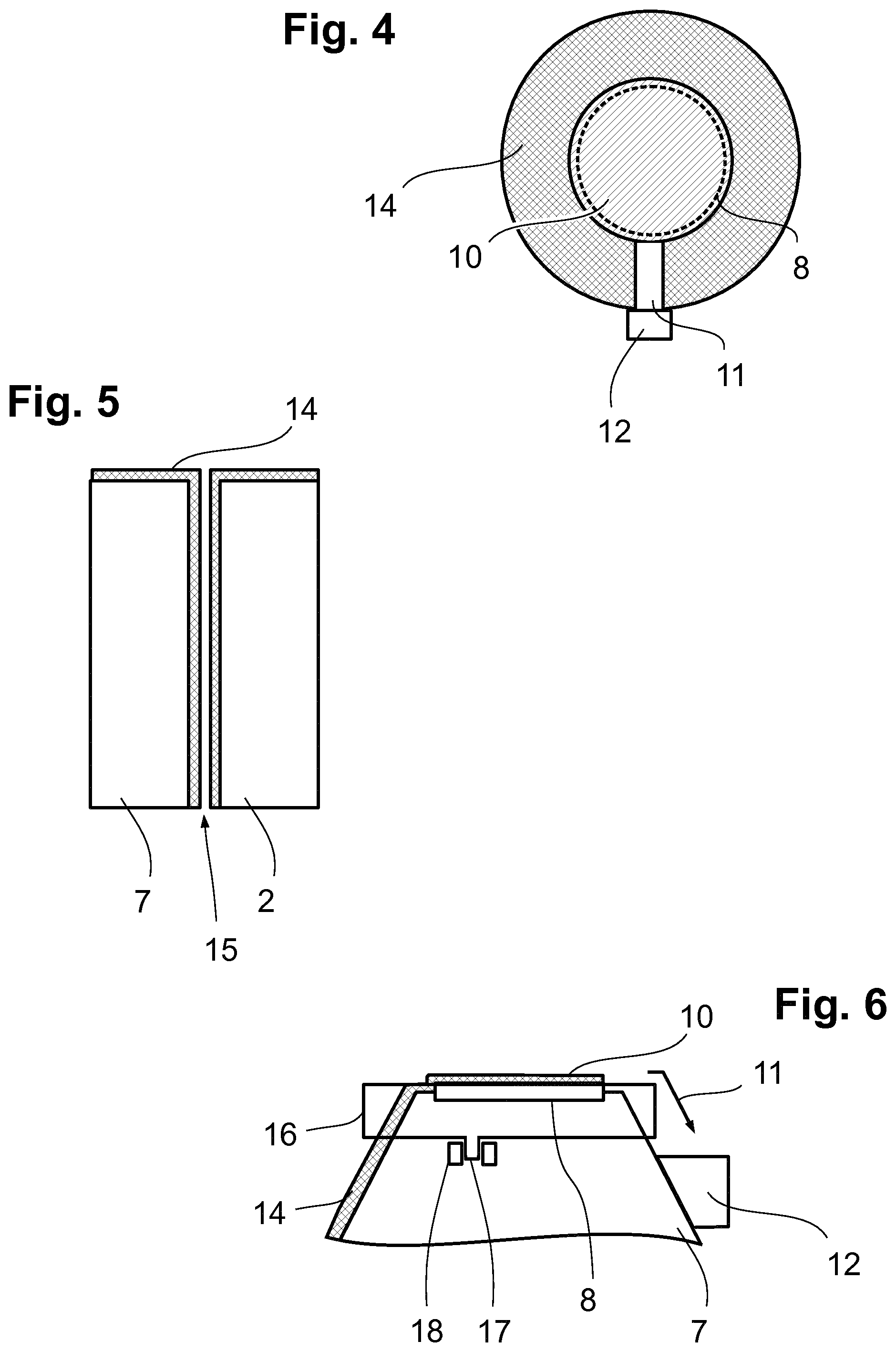
[0022] FIG. 4 shows a plan view of the objective, and
[0023] FIG. 5A to 5D show different states of the microscope objective and of a cover slip during a microscopy process.
DETAILED DESCRIPTION
[0024] FIG. 1 schematically shows an inverted microscope 1, which comprises a nosepiece in a base of a limb 3. A sample stage 4, on which a sample 5 is disposed, is also situated on the limb 3. An illumination device illuminates the sample 5 from above, an objective 7 held in the nosepiece 2 images the illuminated sample 5 from its surface 6 facing the objective (cf. FIG. 2).
[0025] FIG. 2 shows an enlarged view of the relationships between the objective 7 and the sample 5, the latter consisting of a sample carrier 5a with, lying thereon, sample substance 5b and cover slip 5c.
[0026] The objective 7 comprises a front lens 8, on which an immersion liquid 9 is applied. The immersion liquid is selected appropriately depending on the application, i.e., the sample. The objective 7 is designed for a specific immersion liquid in some embodiments. The immersion liquid 9 is located in a gap between the cover slip 5c and the front lens 8 of the objective 7. Alternatively, the objective 7 can image the sample 5b via the sample carrier 5a. A coating 10 is applied in each case to the surface 6 of the cover slip 5c facing the objective 7 and to the front side of the objective 7, it being possible to switch said coating between two states by means of a switching device 14. In a first state, the coating 10 repels the immersion liquid 9. Then, the coating is lipophobic in the case of an oil-based immersion liquid and hydrophobic in the case of a water-based immersion liquid 9. Preferably, it is both lipophobic and hydrophobic, i.e., omniphobic. The switching device 14 is actuated by the control device C and is designed accordingly, depending on the configuration of the coating 10. In the case of a coating 10 which is switched over by electrical means, the switching device 14 is a corresponding wiring and contacting of the coating 10. In the case of a coating 10 which is switched over by light, the switching device 14 is an appropriate light source that acts on the coating 10 in suitable fashion.
[0027] In the state shown in FIG. 2, the coating 10 on the objective 7 is switched to the non-repulsive state and the coating on the cover slip is switched to the repulsive state. This is provided for phases of the microscopy process in which the objective 7 and cover slip 5c are displaced relative to one another, which is visualized in FIG. 2 by an arrow 11. The objective 7 is displaced in this exemplary embodiment. It is equally possible to move the sample carrier 5a or both. So that the immersion liquid 9 does not smear on the cover slip 5c during the displacement along the plotted arrow and is thus lost from the gap between the front lens 8 and the cover slip 5c, the coating 10 disposed on the surface 6 facing the objective 7 is switched to be repulsive for the immersion medium 9. Then, the effect of the coating 10 is that the immersion liquid 9 is repelled at the surface 6 on which the coating 10 has been applied. FIG. 2 elucidates this by a contact angle .alpha. of more than 90.degree. (the counter angle 180.degree.-.alpha. is plotted in the figure).
[0028] The front side of the objective 7, i.e., in particular, the front lens 8, is also provided with the coating 10 and the switching device 14 (this could be the same or a dedicated switching device). In the state of FIG. 2, the coating 10 on the objective 7 is switched into the state that does not repel the immersion liquid 9. In the case of the relative displacement along the arrow, the immersion liquid 9 thus adheres reliably to the microscope objective 7 and is not smeared over the cover slip 5c at the same time.
[0029] In the illustrated embodiment, a further layer 11 extends downward along the objective casing. This is optional. It leaves a drainage channel 12 free, on which the casing and the edge of the front side of the microscope objective 7 are not coated. On account of this lack of coating, an applied immersion liquid 9 runs downward through the drainage channel 12 as soon as the coating 10 is switched to be repulsive. The drainage channel 12 ends in a receptacle 13 that receives the unwanted liquid.
[0030] FIG. 4 shows a plan view of the front side of the objective 7. The coating 10 covers the front lens 8, which is only drawn in dashed lines. The edge, however, is provided with the layer 11. What this achieves is that an immersion liquid that is repelled by the coating 10 cannot cover the surface with the layer 11. By contrast, the drainage channel 12 is not coated at all, and so repelled immersion liquid can flow through the drainage channel 12 to the receptacle 13.
[0031] FIGS. 5A to 5D show various stages that can be used, in particular, in a microscopy process in which a region to be imaged (a so-called region of interest) should initially be found by way of scanning immersion microscopy and then be examined in detail by microscopy. FIG. 5A shows the microscope objective 7 at the start of the microscopy process. The coating 10 is switched into the non-repulsive state, which is symbolized by "+". The contact angle of the immersion liquid 9 on the front side of the microscope objective 7 is less than 90.degree..
[0032] FIG. 5B shows the state in which the region to be imaged is sought. Objective 7 and sample 5 are displaced relative to one another. The objective 7 is switched into the attractive state of its coating 10 and the cover slip 5c is switched into the repulsive state. This is visualized by " " symbols. A contact angle of significantly greater than 90.degree. arises on account of the repulsive property of the coating 10 on the surface 6 of the cover slip 5c. The supplementary angle (180.degree.-.alpha.) is plotted in the figure.
[0033] Once the region of interest has been found, the coating 10 on the cover slip 5c is switched to the attractive state. This can be seen in FIG. 5C. A contact angle .alpha. of significantly less than 90.degree. then arises on the cover slip 5c, and so optimal wetting of the cover slip 5c is ensured when the region to be imaged is examined in detail by microscopy.
[0034] Once the imaging has been completed, the cover slip 5c is switched back into the repulsive state and the objective 7 is lifted off the cover slip. The immersion liquid 9 completely detaches from the cover slip 5c on account of the now repulsive property of the coating 10. No contamination remains.
[0035] Finally, as can be seen in FIG. 5D, the coating on the objective 7 is switched into the repulsive state, resulting in a contact angle .alpha. of significantly greater than 90.degree.. On account of the additional layer 11, the immersion liquid 9 can then only flow through the drainage channel to the receptacle 13 along the arrow shown in FIG. 5D. Where necessary, this process is assisted by pivoting or rotating the objective 7 by the nosepiece 2.
[0036] In the exemplary embodiments described, the switchable coating 10 is provided both on the objective 7 and on the sample carrier 5a or the cover slip 5c (depending on which element lies in front of the objective 7). However, the invention is not restricted to the combination; the switchable coating can also be used only on either the objective 7 or the sample carrier 5a or cover slip 5c.
* * * * *
D00001
D00002
XML
uspto.report is an independent third-party trademark research tool that is not affiliated, endorsed, or sponsored by the United States Patent and Trademark Office (USPTO) or any other governmental organization. The information provided by uspto.report is based on publicly available data at the time of writing and is intended for informational purposes only.
While we strive to provide accurate and up-to-date information, we do not guarantee the accuracy, completeness, reliability, or suitability of the information displayed on this site. The use of this site is at your own risk. Any reliance you place on such information is therefore strictly at your own risk.
All official trademark data, including owner information, should be verified by visiting the official USPTO website at www.uspto.gov. This site is not intended to replace professional legal advice and should not be used as a substitute for consulting with a legal professional who is knowledgeable about trademark law.